Ultair - Ppsokc.com
Ultair - Ppsokc.com
Ultair - Ppsokc.com

You also want an ePaper? Increase the reach of your titles
YUMPU automatically turns print PDFs into web optimized ePapers that Google loves.
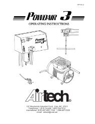
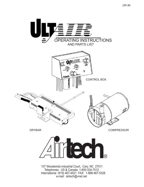
OP-IR<br />
OPERATING INSTRUCTIONS<br />
AND PARTS LIST<br />
CONTROL BOX<br />
DRYBAR<br />
COMPRESSOR<br />
107 Woodwinds Industrial Court, Cary, NC 27511<br />
Telephones: US & Canada 1-800-334-7012<br />
International (919) 467-4521 FAX: 1-888-467-5328<br />
e-mail: airtech@vnet.net
<strong>Ultair</strong> Operating Instructions<br />
CONTENTS<br />
SAFETY PRECAUTIONS .................................................... 1<br />
CONTROL BOX CONTROLS .................................................... 2<br />
EXPLANATION OF OPERATION<br />
Infrared .................................................... 3<br />
Powder Spray .................................................... 4<br />
FILLING THE POWDER JAR .................................................... 6<br />
OPERATING PROCEDURES<br />
Infrared .................................................... 7<br />
Powder .................................................... 8<br />
Air Blowdown .................................................... 10<br />
TEST LIGHTS .................................................... 11<br />
LAMP REPLACEMENT .................................................... 11<br />
ELECTRICAL EXPLANATION<br />
PC Board (Digital Powder Control) .................................................... 12<br />
PC Board (Lamp Control) .................................................... 13<br />
Triacs .................................................... 15<br />
Photosensor .................................................... 15<br />
PREVENTIVE MAINTENANCE .................................................... 16<br />
CLEANING / MAINTENANCE .................................................... 17<br />
WARRANTY .................................................... 17<br />
PARTS ILLUSTRATION .................................................... 18<br />
PARTS LIST .................................................... 19
<strong>Ultair</strong> Operating Instructions<br />
SAFETY PRECAUTIONS<br />
This equipment is listed by Underwriter’s Laboratories under the Graphic Arts<br />
Equipment Standard 775 and presents no hazard when used in accordance<br />
with this manual and all safety labels.<br />
This label is located on<br />
the lamp housing.<br />
When turning the system<br />
off, allow the <strong>com</strong>pressor<br />
to operate for at least 10<br />
minutes before using<br />
blanket wash or any other<br />
flammable solvents.<br />
Use caution when removing paper jams from the chain delivery.<br />
Do not allow press solutions (blanket wash, alcohol solution, inks, etc.) to drip<br />
onto the lamp housing as this may cause fires and/or serious operator injury.<br />
This equipment must be connected to a properly grounded 20 amp, dedicated,<br />
three (3) wire outlet. Failure to do so creates a potential danger of electrical<br />
shock.<br />
WARNING<br />
TO PREVENT SERIOUS DAMAGE TO<br />
BULB HOUSING AND PRESS PARTS,<br />
DO NOT OPERATE SYSTEM WITHOUT<br />
COMPRESSOR OPERATING AND<br />
PROPERLY CONNECTED.<br />
Failure to observe and follow this<br />
warning label can result in damage<br />
to the <strong>Ultair</strong> System, damage to the<br />
press, risk of operator injury and void<br />
manufacturer’s warranty.<br />
Do not operate IR lamp without the heat / chemical shield properly installed.<br />
(Except when used on Multigraphics presses).<br />
Note: The <strong>Ultair</strong> is equipped with an alarm that will sound (high pitch sound)<br />
if the drybar overheats. When the alarm is activated, the IR lamp will not<br />
function until the dryabr cools to normal operating temperature. Alarm<br />
activation is usually caused by inadequate cooling air flow to the drybar,<br />
and service is required. Contact your service represenatative, or contact<br />
Airtech Technical Support at 1-800-334-7012.<br />
1
<strong>Ultair</strong> Operating Instructions<br />
CONTROL BOX CONTROLS<br />
Rocker Switch - (Black) Activates the <strong>com</strong>pressor and supplies power to the system.<br />
Spray Length Control / Powder On-Off - Adjusts the length of powder spray cycle starting<br />
with the lead edge of the sheet. Turning this knob fully counterclockwise turns the<br />
powder spray off.<br />
Intensity Control / IR Off - Provides infrared lamp intensity settings. Turning this knob<br />
fully counterclockwise turns the infrared lamp off.<br />
Powder Concentration Control - Adjusts the concentration or density of powder spray<br />
particles delivered to each sheet.<br />
Air Blowdown Control - Adjusts the amount of air blowdown pressure on the sheet at<br />
the paper delivery area. (Not all models have air blowdown).<br />
Power Light -<br />
Strobing: Indicates power is “ON”.<br />
Continuous On: Indicates powder spray or infrared lamp is in operation.<br />
2
<strong>Ultair</strong> Operating Instructions<br />
EXPLANATION OF INFRARED OPERATION<br />
The infrared lamp can be operated independently or with the powder spray. The lamp is<br />
a constant source of high intensity light in the short wave infrared spectrum. The lamp<br />
transfers its energy to the paper in the form of heat. The increased temperature causes<br />
the ink to “set” at a faster rate than normal.<br />
Generally, for every 18 F incremental rise in temperature,<br />
ink curing time is reduced by one-half. (ie. an ink that<br />
normally cures in two hours would cure in thirty minutes<br />
if paper temperature is raised by 36 F).<br />
Caution: It is possible to “overheat” the paper. Some<br />
characteristics of overheating are: loss of gloss,<br />
misregister between runs, paper curl, and cracking<br />
at the fold. These problems can be corrected by<br />
using lower intensity settings.<br />
The “INTENSITY” control provides various lamp intensities enabling the operator to<br />
<strong>com</strong>pensate for such variables as press speed, paper stock, ink coverage, and ink color.<br />
(See re<strong>com</strong>mended settings below).<br />
The effectiveness of infrared drying will vary from job to job. Infrared drying will decrease<br />
drying time on any job and will eliminate offset on the majority of runs. However, runs<br />
with heavy ink coverage, fast press speeds, or coated stock, may require the use of<br />
powder spray to guarantee the prevention of offset.<br />
Press<br />
Speed<br />
sht/hr<br />
Type of Paper / % Ink Coverage<br />
20# Bond 70# Linen 70# Matte 70# Gloss 70# Coated (CSI)<br />
40% 70% 40% 70% 40% 70% 40% 70% 40% 70%<br />
4200<br />
7 5<br />
5<br />
5<br />
3<br />
2<br />
3<br />
3<br />
2<br />
4<br />
5400<br />
7<br />
6<br />
7<br />
7<br />
7<br />
5<br />
7<br />
5<br />
6<br />
6<br />
6500<br />
7<br />
7<br />
7<br />
7<br />
7<br />
6<br />
7<br />
6<br />
7<br />
7<br />
3
<strong>Ultair</strong> Operating Instructions<br />
EXPLANATION OF POWDER SPRAY OPERATION<br />
Powder consumption should be minimized with the use of infrared, however; the operator<br />
must determine when powder spray is necessary. We re<strong>com</strong>mend using the powder<br />
spray as a supplement to the infrared drying to guarantee the prevention of offset while<br />
minimizing drying time. The amount of powder applied to the paper can be greatly reduced<br />
when used in <strong>com</strong>bination with infrared drying.<br />
The <strong>Ultair</strong> sprays powder only when the press is on impression. The system is designed<br />
to begin spraying powder when the lead edge of the printed sheet is under the spray bar.<br />
The spray bar is designed to spray an even mist of powder across the entire width of the<br />
paper as it passes underneath. The <strong>Ultair</strong> also provides control of the length of powder<br />
spray, allowing the operator to spray any fraction of a sheet or any size sheet encountered.<br />
This feature helps eliminate wasteful powder overspray.<br />
4
<strong>Ultair</strong> Operating Instructions<br />
The <strong>Ultair</strong> is equipped with “Automatic Speed-Sensing” which senses changes in press<br />
speed during a run and automatically adjusts the length of spray to maintain the desired<br />
length originally set.<br />
The air exits on the air blowdown tube are designed to direct pressurized air against the<br />
paper as it is released into the delivery pile. This helps eliminate paper roll and curl,<br />
allows for faster press speeds, and aids in the orderly stacking of the printed sheets.<br />
Caution: Do not cover all three air exits because this will create back-pressure in<br />
the system.<br />
5
<strong>Ultair</strong> Operating Instructions<br />
FILLING THE POWDER JAR<br />
Remove powder container by unscrewing<br />
(CCW) the plastic jar and lowering it<br />
until it clears the “I-Tube”.<br />
Knob<br />
Carefully fill the powder jar with powder<br />
leaving approximatlely 1/2 inch space<br />
from the neck of the jar to the top of<br />
the powder.<br />
Manifold<br />
Important: Do Not Overfill the Powder Jar.<br />
During operation, the powder is continuously<br />
aerated and space must be left in the container<br />
for the proper mixture of powder and air to take<br />
place.<br />
Wipe excess powder from the top rim of<br />
the jar and replace by turning (clockwise)<br />
until it seals snuggly against the rubber<br />
gasket.<br />
Refill when the container is approximately<br />
4/5 empty. Do not allow excess powder<br />
to build-up around the rubber gasket or<br />
jar threads.<br />
When removing or replacing the jar, be careful<br />
not to break the “I-Tube”.<br />
I-Tube<br />
I-Tube Aerator<br />
Rubber<br />
Gasket<br />
Wipe Rim<br />
After Filling<br />
Do Not Fill<br />
Above This<br />
Level<br />
Powder Jar<br />
Do Not Let<br />
Powder Drop<br />
Below This<br />
Level<br />
6
<strong>Ultair</strong> Operating Instructions<br />
INFRARED OPERATING PROCEDURES<br />
Push the black rocker switch “ON”. This switch activates the <strong>com</strong>pressor which must be<br />
on while operating the infrared system, powder spray system, or air blowdown.<br />
Turn the “INTENSITY” knob clockwise. (Infrared works on impression only).<br />
Note: Airtech strongly suggests allowing the <strong>com</strong>pressor to operate for approximately<br />
5-10 minutes, as a cooling aid after the job runs, and in between two or<br />
more pass jobs. This can be ac<strong>com</strong>plished by leaving the rocker switch in the<br />
“ON” position for the specified time.<br />
Start the press and begin feeding paper.<br />
As the lead edge of the sheet reaches the lamp assembly, the lamp will <strong>com</strong>e on. In<br />
cold start-up conditions, it may require running up to 100 set-up sheets to be run to<br />
allow the lamp assembly to reach optimum drying temperature.<br />
The lamp will remain on until the last sheet is fed through the press.<br />
The “INTENSITY” control can be set at any number of settings depending on paper<br />
stock, ink coverage, ink type, or press speed.<br />
WARNING:<br />
TO PREVENT SERIOUS DAMAGE TO<br />
BULB HOUSING AND PRESS PARTS,<br />
DO NOT OPERATE SYSTEM WITHOUT<br />
COMPRESSOR OPERATING AND<br />
PROPERLY CONNECTED.<br />
Note: The <strong>Ultair</strong> is equipped with an alarm that will sound (high pitch sound)<br />
if the drybar overheats. When the alarm is activated, the IR lamp will not<br />
function until the dryabr cools to normal operating temperature. Alarm<br />
activation is usually caused by inadequate cooling air flow to the drybar,<br />
and service is required. Contact your service represenatative, or contact<br />
Airtech Technical Support at 1-800-334-7012.<br />
7
<strong>Ultair</strong> Operating Instructions<br />
POWDER OPERATING PROCEDURES<br />
Push “ON” the black rocker switch. (This activates the <strong>com</strong>pressor).<br />
Turn the “SPRAY LENGTH” control counterclockwise until just before reaching the “click”<br />
or the “OFF” position.<br />
Start the press and begin feeding paper through the press.<br />
While watching the powder indicator light (located on the spray bar) adjust the “SPRAY<br />
LENGTH” control clockwise gradually until the powder indicator light turns off just as the<br />
tail edge of the sheet (or portion of the sheet you wish to spray with powder) passes<br />
under the spray bar.<br />
Note: The <strong>Ultair</strong> is equipped with “Automatic Speed-Sensing”. This senses changes in<br />
press speed during a run and automatically adjusts length of spray to maintain the<br />
desired length originally set.<br />
8
<strong>Ultair</strong> Operating Instructions<br />
Adjust the “POWDER CONCENTRATION” knob to the desired powder concentration per<br />
each powder spraying cycle. At this point, the system automatically begins spraying<br />
powder as the lead edge of the sheet reaches the spray bar, as indicated by the powder<br />
indicator light, and can be adjusted for the concentration of powder delivered to each<br />
sheet and the area covered with powder.<br />
For <strong>Ultair</strong>s equipped with “Air Blowdown”, air is directed downward on the sheet to aid<br />
in delivery. The volume of air delivered to the sheet is adjustable by turning the “Air<br />
Blowdown Control” knob.<br />
To derive maximum benefit from your <strong>Ultair</strong> System, give careful attention to the<br />
“Powder Concentration” adjustment. We re<strong>com</strong>mend using the lightest powder<br />
application possible to eliminate your offsetting problem. Heavy powder applications<br />
can cause problems in running subsequent colors or with after-press operations, and<br />
very heavy powder applications may render the job unusable.<br />
We re<strong>com</strong>mend Airtech medium grade “non-offset” spray powder with a particle size<br />
of 25 microns. (1 micron equals approximately 1/1000 of a millimeter). Do not use<br />
powders that are micro encapsulated. Micro encapsulated powders contain silicone.<br />
Silicone melts at the elevated temperatures associated with infrared ink drying and will<br />
clog your system. For more information, contact Airtech direct using the numbers listed<br />
on page 17.<br />
9
<strong>Ultair</strong> Operating Instructions<br />
AIR BLOWDOWN OPERATING PROCEDURES (NO POWDER)<br />
Push the black rocker switch “ON”. The <strong>com</strong>pressor is “ON” and air blowdown is “ON”.<br />
Turn the “SPRAY LENGTH” knob fully counterclockwise until a “click” is heard, and the<br />
arrow lines up with the “POWDER OFF”.<br />
Turn the “INTENSITY” control knob fully counterclockwise until a “click” is heard, and the<br />
arrow lines up with “IR OFF”.<br />
Adjust the “AIR BLOWDOWN” control to the desired level depending on the stock being<br />
used.<br />
Position the plastic slide collars on the air blowdown tube to direct the air to best suit the<br />
application.<br />
10
<strong>Ultair</strong> Operating Instructions<br />
TEST LIGHTS<br />
Your <strong>Ultair</strong> is equipped with two test lights.<br />
Power:<br />
Test:<br />
When the system is turned on, the “POWER” light will strobe until the system is<br />
used. Then, the powder light will glow continuously when in operation. This<br />
indicates that the microprocessor is functioning properly.<br />
Located under the small window on the right side of the control box, the test light<br />
flashes at the rate of press speed and indicates accurate trigger / impression<br />
signal from the press. (Caution: Do not change any of the dip switch settings as<br />
this will cause damage to your system).<br />
The two test lights will help diagnose a problem with your system. If any one<br />
of the two lights is not operating properly, please contact the dealer from<br />
whom your <strong>Ultair</strong> was purchased, or call Airtech Toll Free at 1-800-334-7012.<br />
International residents call (919) 467-4521. To assure prompt assistance,<br />
please have Airtech model, serial number, and s/date from your control box.<br />
1. Disconnect power to control box.<br />
LAMP REPLACEMENT<br />
2. Remove lamp housing from the chain delivery.<br />
3. Remove the 2 screws from the top of the sheet metal housing. (This will release<br />
the housing from the reflector assembly).<br />
4. Unplug the wire leads from each end of the lamp at the plastic connectors.<br />
5a. (For 2000 Watt Systems) Remove the 2 screws securing the aluminum end<br />
plate on one end of the bulb and remove bulb. Save ceramic sleeve holders.<br />
5b. (For 1350 Watt Systems) Carefully push the ceramic lamp ends out of the bulb<br />
clips and remove the lamp.<br />
6. Important! - Clean the new bulb with isopropyl alcohol after replacing.<br />
Fingerprints on the bulb will cause lamp failure.<br />
7. Reverse steps 1-5 to install new lamp.<br />
11
<strong>Ultair</strong> Operating Instructions<br />
ULTAIR ELECTRICAL EXPLANATION<br />
I. PC BOARDS<br />
A. DIGITAL POWDER CONTROL: (DPC)<br />
1. This board is mounted horizontally in the control box. It controls the<br />
powder spray function (voltage to the solenoid “connector #8” and<br />
indicator light “connector A”) and sends line voltage “connector #9”<br />
to the LAMP CONTROL BOARD when the press is on impression.<br />
(This voltage “tells” the LAMP CONTROL BOARD that the press<br />
is on impression).<br />
2. The “DPC” Board uses a microprocessor to calculate the length of<br />
time to energize the solenoid for each sheet. It considers 3 inputs.<br />
a. Length control potentiometer (500k ohm) “connector #4”.<br />
b. Length control switch (this switch is incorporated into the length<br />
control pot) “connector #5”.<br />
c. The trigger input is derived differently for each press model.<br />
The board uses this input for a timing signal to start the spray<br />
cycle AND to calculate the speed of the press. This is<br />
“connector #3”. The board knows the speed of the press and<br />
will automatically make changes to length control if the press<br />
speed changes, (the length control knob will not turn).<br />
3. Test lights for DPC Board:<br />
a. “Trigger” light (GREEN)<br />
This light is on the SIDE of the control box and can be viewed<br />
through a clear plastic window affixed to the side panel. This<br />
light should light ONCE every time a sheet passes ON<br />
IMPRESSION. This is a handy diagnostic tool when troubleshooting<br />
the ULTAIR. This should be the first check point whenever<br />
a problem with the solenoid function or IR lamp operation is<br />
encountered.<br />
b. “Power” light (RED)<br />
This light indicates power to the DPC board. When this light<br />
strobes, it indicates a waiting condition. The microprocessor<br />
is operating and waiting for a press signal to start operating the<br />
solenoid valve. When this light stops strobing and lights solid,<br />
it has recognized the trigger signal from the press. IF the length<br />
control SWITCH is on, the board will energize the solenoid for<br />
12
<strong>Ultair</strong> Operating Instructions<br />
a short period of time every time the board receives a trigger<br />
signal. The length of time the solenoid valve is held open<br />
depends on where the length control pot is set by the operator.<br />
Of course, the solenoid valve should be open as long as the<br />
sheet of paper is under the drybar.<br />
c. “Indicator” light (YELLOW) located on the Drybar:<br />
The indicator light is on whenever the solenoid valve is engaged<br />
to show: visually when the unit is spraying powder to aid<br />
the operator in setting the length control properly.<br />
4. Power supply for DPC Board:<br />
a. The current DPC boards have an on board transformer. (This<br />
is evidenced by a “RED” power light: older models have a<br />
green power light and draw power (7 VAC) from the transformer<br />
mounted to the top cover,”connector #1”. Current<br />
models get line voltage on “connector #6”, i.e. 110-220 VAC.<br />
The board uses an on-board switch to select 110 or 220 VAC.<br />
B. LAMP CONTROL BOARD: (LCB)<br />
1. This board is mounted vertically in the control box. It controls<br />
the infrared lamp on and off function (current to one leg of the<br />
IR lamp power through 1 triac). and intensity control (current<br />
goes to the other leg of the IR lamp through the other triac).<br />
NOTE: The 2 triacs that control the lamp vary the CURRENT<br />
not the voltage!!! A digital volt meter will not read accurate<br />
power to the lamps and will most always read line voltage<br />
(110 VAC-220 VAC) even if the lamps are OFF!!!<br />
2. The “LCB” board’s only function is to control power to the<br />
lamp via the triacs. It considers 4 inputs:<br />
a. Photosensor input, “connector #20” inside the chain delivery,<br />
looks for paper jams and must be making and breaking about<br />
1 time every second to keep the lamps on!<br />
b. Thermal switch, “connector #19”, mounted inside the IR drybar<br />
must maintain a temperature below 150 C (302 F) to prevent<br />
an open circuit condition. This thermal switch is simply providing<br />
a “short circuit” to connector #19 when temperatures are safe<br />
inside the drybar.<br />
Note: The <strong>Ultair</strong> is equipped with an alarm that will sound (high pitch sound)<br />
if the drybar overheats. When the alarm is activated, the IR lamp will not<br />
function until the dryabr cools to normal operating temperature. Alarm<br />
activation (open thermal switch) is usually caused by inadequate cooling air flow<br />
to the drybar, and service is required. Contact your servi ce representative, or<br />
contact Airtech Technical Support at 1-800-334-7012.<br />
13
<strong>Ultair</strong> Operating Instructions<br />
c. Intensity control potentiometer (500k ohm), “connector #10”<br />
is a variable resistance to the LCB for intensity control.<br />
d. Intensity control switch “connector #16” is incorporated<br />
into the intensity control pot. This provides the line voltage<br />
mentioned earlier from the DPC board to “signal” the LCB<br />
board the press is on impression. The switch is simply a<br />
link between the DPC board, “connector #9” and the LCB<br />
board “connector #16” and only switches the HOT side of the<br />
line voltage (110-220 VAC). If the intensity pot is switched<br />
“off” the IR lamp will not work EVEN if the photosensor is<br />
pulsing the LCB board and the thermal switch is closed.<br />
As you can see, several inputs MUST be functioning to keep<br />
the IR lamp on:<br />
1. Photosensor pulsing.<br />
2. Thermal switch is closed.<br />
3. HOT side of line voltage from intensity switch<br />
(110-220 VAC) which also means the DPC board has<br />
detected the press is actually on impression.<br />
3. Test lights for LCB board:<br />
a. Power light (GREEN):<br />
This light indicates there is a low voltage on the board,<br />
“connector #17, and is 14 VAC with a center tap. There is<br />
a 1 amp 250 volt fuse on the board for this supply.<br />
b. Infrared lamp power light (RED):<br />
This light <strong>com</strong>es on ONLY when , #1 the thermal fuse is closed<br />
and, #2 when the photosensor is pulsing, ie. making and breaking<br />
with the gripper bars moving. (It does not necessarily indicate<br />
press “ON” impression as the LCB board also needs Hot side of<br />
line voltage on “connector #16” to turn the lamps on.) This red<br />
light is a handy diagnostic tool for checking the photosensor<br />
signal to the LCB board and thermal switch.<br />
4. Power Supply for LCB Board:<br />
The LCB board requires 14 VAC regulated to 12 VDC. 14 VAC is<br />
provided by the external transformer via “connector #17”. This<br />
can be measured across the 2 outside green wires on the<br />
connector. This is a 3 wire connection with center wire being<br />
a center tap. The center tap is no longer used by the board.<br />
(It was used with older <strong>Ultair</strong>s for the 7 VAC needed for the DPC<br />
board, before the on-board transformer).<br />
14
<strong>Ultair</strong> Operating Instructions<br />
II.<br />
TRIACS:<br />
A. The <strong>Ultair</strong> control box contains 2 triacs, one for each leg of the<br />
line voltage 110-220 VAC to switch the IR lamp on and off.<br />
One triac only turns on if safety conditions are met,(ie.<br />
photosensor pulsing and red light on LCB board is lit). The<br />
other triac varies the current to the lamp directly proportional<br />
to the Intensity control pot. Again, trying to measure the<br />
voltage to the lamp with a digital volt meter is not accurate as<br />
the triacs switch the current, not the voltage. You will almost<br />
always read line voltage when reading across the output to<br />
the lamp, (even when the lamp is off).<br />
B. The triacs are not easily checked in the field with a digital volt<br />
meter and are usually replaced only when all other problems<br />
are eliminated or they are replaced in conjunction with the<br />
LCB board when either is suspected.<br />
III.<br />
PHOTOSENSOR<br />
A. With the exception of all MULTIGRAPHICS presses, the<br />
<strong>Ultair</strong> uses an external photosensor mounted in the chain<br />
delivery to detect sheet jams. This photosensor will shut down<br />
the IR lamp if the beam is not made and broken once every<br />
second; even if the press is still running and is on impression.<br />
This sensor “bounces” a beam off of a polished reflector<br />
installed under the sensor about 4-5 inches away from the lens.<br />
It is important to keep this reflector surface clean. When properly<br />
aligned the “GREEN” light will glow on the right side of the<br />
photosensor. If the “RED” light is glowing, please adjust the<br />
sensor alignment until the “GREEN” light reappears. This adjustment<br />
normally does not require much movement to bring the<br />
sensor back into alignment. (THE SENSOR IS NOT DESIGNED<br />
TO FUNCTION WITH A REFLECTOR CLOSER THAN 4 INCHES).<br />
Keep this in mind when trying to troubleshoot the sensor.<br />
15
<strong>Ultair</strong> Operating Instructions<br />
PREVENTIVE MAINTENANCE<br />
In order to maximize performance, please follow these preventive maintenance procedures.<br />
1. Do not allow lubricants / solvents to drip onto the control box or the IR lamp housing.<br />
2. If any substance (including fingerprints) should <strong>com</strong>e in contact with the glass<br />
infrared lamp, carefully wipe lamp when lamp is cold, with a lint-free cloth and<br />
isopropyl alcohol.<br />
Note: Fingerprints on lamp will cause reduced lamp life!<br />
3. If powder be<strong>com</strong>es contaminated (ie. looks clumpy, not fluid) empty the powder<br />
jar. Before refilling, wipe the rim of the powder jar with a clean, dry cloth before<br />
reassembling.<br />
4. Do not force the concentration knob past the normal stopping place.<br />
5. Periodically remove the <strong>com</strong>pressor filters and clean them using pressurized<br />
air.<br />
6. Powder buildup on the infrared lamp will cause a decrease of intensity. Occasional<br />
cleaning with a soft bristle brush or cloth may be necessary.<br />
Should Your System Be<strong>com</strong>e Clogged:<br />
1. Disconnect the vinyl powder tube from the spray bar and blow pressurized air<br />
directly through the nozzles (40 psi max.).<br />
2. Carefully remove the “I-Tube”. Clear the “I-Tube” of any powder residue. Apply<br />
air pressure to the hole and the non-threaded hole next to the I-tube in the<br />
manifold. This will clear the tubes inside the control box.<br />
16
<strong>Ultair</strong> Operating Instructions<br />
CLEANING / MAINTENANCE<br />
Note: Proper cleaning of these <strong>com</strong>ponents is absolutely necessary for continued<br />
maximum performance and to reduce the risk of fire hazard.<br />
1. Once a week, using a soft bristle brush, clean the underside of the lamp housing<br />
including the glass bulb and parabolic reflector (Note: fingerprints on the lamp<br />
will cause lamp failure).<br />
2. Clean the photosensor (mounted to the back of the lamp housing) on a regular<br />
basis depending on powder usage. (Powder on photocells can cause false jams).<br />
3. For models that use a blue photosensor, clean the stainless steel reflector<br />
mounted approximately 4 - 5” below the photosensor.<br />
12 MONTH LIMITED WARRANTY<br />
The Airtech <strong>Ultair</strong> is designed to provide years of trouble free performance. Should you<br />
experience any difficulty, contact you local Airtech dealer or call Airtech.<br />
Toll Free: 1-800-334-7012 International: (919) 467-4521<br />
The Airtech <strong>Ultair</strong> System is backed by a full twelve (12) month limited warranty from the<br />
date of manufacture. The warranty is extended to the original buyer against defects in<br />
workmanship or materials under normal use. For any product or part believed to be<br />
defective within warranty, first write or call the dealer from whom the product or part was<br />
purchased. Dealer will give additional directions. If dealer is unable to satisfactorily<br />
solve the problem, call or write Airtech International, Inc. giving dealer’s name, date and<br />
number of dealer’s invoice, product model number and serial number, and describe the<br />
nature of the defect. Any part or product that is determined to be defective in material<br />
or workmanship and returned to Airtech, shipping costs prepaid, will be replaced or<br />
repaired at Airtech’s option. Airtech’s liability in all events is limited to the purchase<br />
price paid. If the product was damaged in transit to you, file a claim with the carrier.<br />
17
<strong>Ultair</strong> Operating Instructions<br />
CONTROL BOX PARTS ILLUSTRATION<br />
MODEL NUMBERS<br />
AB70IR-1-13 HBQMIR-2-20 RY32IR-2-20<br />
AB70IR-2-20 HM23IR-2-20 RY2CIR-2-20<br />
AB98IR-1-13 HMRLIR-2-20 RY2MIR-2-20<br />
AB98IR-2-20 HMRVIR-2-20 RY4CIR-2-20<br />
AM16IR-1-13 RY28IR-1-13 TK47IR-1-13<br />
AM16IR-2-13 RY28IR-2-20 TK47IR-2-20<br />
AM38IR-1-13 RY32IR-1-13 RY2HIR-2-20<br />
TKR2IR-2-20<br />
RY2HIR-2-20<br />
18
<strong>Ultair</strong> Operating Instructions<br />
PART NUMBERS FOR 1350 / 2000 WATT ULTAIR CONTROL BOX:<br />
NUMBER AIRTECH PART # DESCRIPTION<br />
1 78304-9000AA Solenoid Valve (110 VAC)<br />
78304-9000A2A Solenoid Valve (220 VAC)<br />
2 62030 Plastic Elbow - small<br />
3 6822306A Tubing Reduction Manifold<br />
4 14NPT-38E Plastic Elbow - large<br />
5 0701-153 Plastic Tubing Fitting<br />
6 14T38 1/4 x 3/8 Clear Vinyl Tubing<br />
7 38NB916 3/8 x 9/16 Braided Vinyl Tubing<br />
8 14ECT38 Black Conductive Tubing<br />
Note: This is not for use in the drybar.<br />
9 41316001 Triac<br />
10 632SHN Nut for Triac<br />
11 41318010 Power Switch<br />
12 1-GIRCBF-BLK Control Box Front<br />
13 12063 Small Knob<br />
14 1202AB3 Large Knob<br />
15 6831501A Air BLowdown Valve<br />
16 67141121 PC Board - Powder<br />
17 84119107 Manifold<br />
18 6731103A Transformer (110VAC)<br />
67312061 Transformer (220 VAC)<br />
19 67611141 Potentiometer (Powder)<br />
20 6762110A Potentiometer (Infrared)<br />
21 LCB-1 PC Board - Lamp (110VAC)<br />
LCB-2<br />
PC Board - Lamp (220VAC)<br />
22 41743000 Fuse Holder<br />
23 41722002 Fuse 20 Amp Ceramic<br />
24 RICH-8-01 Plastic Stand Off<br />
25 HEY-2497 Plastic Plug<br />
26 7P-2-1237 Strain Relief<br />
27 41532301 Pump Outlet (IEC)<br />
28 2879001B PCB Mounting Bracket<br />
29 I-14T12R Aeration Tube (I-Tube)<br />
30 167838GA Jar Gasket<br />
19
<strong>Ultair</strong> Operating Instructions<br />
NUMBER AIRTECH PART # DESCRIPTION<br />
31 41-440 Powder Jar<br />
32 67514261 Power Cord (110 VAC)<br />
67514251 Power Cord (220 VAC)<br />
33 IR-VENT Vent Plug<br />
34 4239023A Dip Switch Cover<br />
35 47323223 Back Cover Screw<br />
36 GIRCBB-BLK Back Cover<br />
37 2879002C Triac Plate<br />
38 5X442 Hose Clamp<br />
39 5250-2 Tube Black Fitting<br />
40 6763109A Internal Photosensor<br />
(Not Shown)<br />
Note: Used on AM Multigraphics systems<br />
NOTE:<br />
Control boxes made after 0198 serial date have a different style powder<br />
control board with on-board transformer. Control boxes with this new<br />
board have a “RED” power light as viewed from the front of the control<br />
box. Please note this information when ordering replacement PC board<br />
or powder potentiometer (length control).<br />
20
PRESS CHEM SHIELD GLARE SHIELD TRIGGER/SNAP BD TUBE DRYBAR SENS MTG BRKT COOL TUBE<br />
AB DICK<br />
9800 1-IR17CS-A / 9810-50 6533018A SSDBLA 34110761 63233012 / 220VAC 26390212 34410771<br />
65CS70-A / 9870 6533019A / 8820 63231152 / 110VAC<br />
RYOBI<br />
3302M 6513027A 3019028A 6785224A NONE 63253231 2639018A 3441032B<br />
3302H<br />
3304H 65130611 / Vertical 30190471 67852121 NONE 63253231 65430701 3441032B<br />
65130621 / Horizontal<br />
2800 6513008A 6533011A SS75 34410791 63213072 / 220VAC / 28-32 2639010C 34410781<br />
3200 6513009A 6533010A SS75 34410791 63211081 / 110VAC / 28-32 2639010C 34410781<br />
TOKO<br />
4750 NONE 6533018A SS4750 3421025A 6321309A / 220VAC 2739019A 3441024B<br />
6323113A / 110VAC<br />
MULTI<br />
1650 & 3850 NONE 6533018A 67717131 / 1650 3421006B 6342101B / 220VAC 65130461 / KIT* 3441004E<br />
65430011 / 3850 6342201B / 110VAC<br />
HAMADA<br />
234 65130661 Upper 30000481 67852151 NONE 63213251 26310311 34410781<br />
65130671 Lower<br />
RS / VS 34 65130681 30000481 67852151 NONE 63213241 26319311 34410781<br />
RS34LS-II 65130711 30000481 67852151 NONE 63213271 26390381 34410781<br />
HEIDELBERG<br />
QM46 QMCHEM-KIT NONE 6785231B NONE 63053211 26390821 34410701<br />
*Includes fiber optic sensor and brackets (PT# FE-T4T for fiber optic cables only)<br />
21