26/26D Stitcher Head - Ppsokc.com
26/26D Stitcher Head - Ppsokc.com
26/26D Stitcher Head - Ppsokc.com

Create successful ePaper yourself
Turn your PDF publications into a flip-book with our unique Google optimized e-Paper software.
DELUXE STITCHER<br />
C O M P A N Y I N C .<br />
<strong>Head</strong> Serial Number :<br />
Date Purchased :<br />
Where Installed:<br />
(make/model of machine)<br />
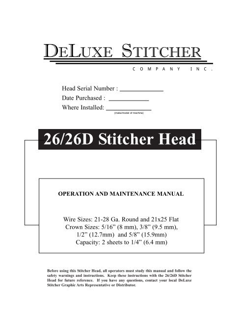
<strong>26</strong>/<strong>26</strong>D <strong>Stitcher</strong> <strong>Head</strong><br />
OPERATION AND MAINTENANCE MANUAL<br />
Wire Sizes: 21-28 Ga. Round and 21x25 Flat<br />
Crown Sizes: 5/16” (8 mm), 3/8” (9.5 mm),<br />
1/2” (12.7mm) and 5/8” (15.9mm)<br />
Capacity: 2 sheets to 1/4” (6.4 mm)<br />
Before using this <strong>Stitcher</strong> <strong>Head</strong>, all operators must study this manual and follow the<br />
safety warnings and instructions. Keep these instructions with the <strong>26</strong>/<strong>26</strong>D <strong>Stitcher</strong><br />
<strong>Head</strong> for future reference. If you have any questions, contact your local DeLuxe<br />
<strong>Stitcher</strong> Graphic Arts Representative or Distributor.
W A R N I N G !<br />
<strong>26</strong>/<strong>26</strong>D <strong>Stitcher</strong> <strong>Head</strong><br />
Machine operators and others in the work area should always wear<br />
safety glasses to prevent serious eye injury from<br />
fasteners and flying debris when loading, operating,<br />
or unloading this machine.<br />
Do not operate this stitcher head without all stitcher machine<br />
guards in place. Do not modify the guards in any way.<br />
Always disconnect the power supply before removing<br />
any guards for servicing.<br />
Never operate the machine with wire feeding through<br />
the head unless there is stock above the clinchers,<br />
otherwise serious damage may result.<br />
Always turn power off when making adjustments. Always<br />
disconnect the power cord before any disassembly work.<br />
2
Table of Contents<br />
Introduction ........................................................................................................4<br />
Part Number Definition....................................................................................5<br />
Specifications ....................................................................................................6<br />
Installation ......................................................................................................8<br />
Pre-Inspection ................................................................................8<br />
Inspection ......................................................................................8<br />
Mounting ......................................................................................10<br />
Operation ......................................................................................................12<br />
Wire Threading ............................................................................12<br />
Wire Straightening ........................................................................13<br />
Adjustments and Settings ............................................................14<br />
Maintenance ......................................................................................................18<br />
Lubrication ....................................................................................18<br />
Cleaning ........................................................................................19<br />
How to Order Spare Parts..............................................................20<br />
Replacing Spare Parts ..................................................................20<br />
Troubleshooting................................................................................................25<br />
Formed Staple Chart......................................................................25<br />
Appendices ......................................................................................................27<br />
Exploded Drawings ........................................................................27<br />
Part Number/Description Cross Reference ..................................37<br />
Variable Crown and Wire Sizes ..................................................................40<br />
Registration Card ............................................................................................43<br />
Wear/Replacement Parts ..............................................................................44<br />
Warranty ......................................................................................................45<br />
3
Introduction<br />
The DeLuxe <strong>Stitcher</strong> Company 2001DHD Series, 2301DHD Series, <strong>26</strong>01AHD<br />
Series, <strong>26</strong>01DHD and <strong>26</strong>01 EHD Series Wire <strong>Stitcher</strong> <strong>Head</strong>s are basically identical<br />
with respect to operation. Variations occur in some of the <strong>com</strong>ponent parts due to<br />
adapting that basic head to single stitch and gang stitch machines and also due to<br />
model design changes. Variations between the <strong>26</strong>01AHD Series and the 20001DHD<br />
Series can be recognized by a <strong>com</strong>parison of the Swivel Holders.<br />
These heads were designed over 75 years ago, yet they still remain the most<br />
popular stitcher head sold in the world. The <strong>26</strong>/<strong>26</strong>D heads are reliable, durable and<br />
economically priced.<br />
Typical Style Uses:<br />
2001DHD ........................................................No. 2 and No. 10 Wire <strong>Stitcher</strong>s<br />
2301DHD ................................................................No. 23 Wire <strong>Stitcher</strong>s<br />
<strong>26</strong>01EHD ........................................................No. 16E and 17E Wire <strong>Stitcher</strong>s<br />
<strong>26</strong>01DHD/<strong>26</strong>01AHD ........................................Automatic Saddle-<strong>Stitcher</strong>s,<br />
................................................................Gang-<strong>Stitcher</strong>s, Multibinders and Others<br />
Examples of Replacement <strong>Head</strong>s for OEM Users*:<br />
AM Graphics / Sheridan<br />
455, 562, 690............................................................<strong>26</strong>01DSHD251/2<br />
AM Graphics / Sheridan 705 ....................................<strong>26</strong>01DOHD251/2<br />
Bourg ........................................................................ <strong>26</strong>01DOHD251/2<br />
Christensen ................................................................ <strong>26</strong>01DSHD251/2<br />
Macey Multibinder ................................ <strong>26</strong>01AOHD251/2 and <strong>26</strong>01DSHD251/2<br />
McCain ...................................................................... <strong>26</strong>01DCMC251/2<br />
Pitney Bowes ........................................ <strong>26</strong>01APBHD251/2 and <strong>26</strong>01APB2HD251/2<br />
Rosback .................................................................... <strong>26</strong>01AOHD251/2<br />
* These are just a few examples of the replacement heads available for these OEM’s.<br />
4
Part Number Definition<br />
The part number for each <strong>Stitcher</strong> <strong>Head</strong> can be used to define the stitcher head itself, in most<br />
cases. The <strong>Head</strong>’s model type, mounting style, nominal wire size and crown size can all be<br />
determined from the part number.<br />
<strong>26</strong>01 D S HD 24 1/2<br />
1/2 = Crown size in inches<br />
24 = Nominal wire size<br />
HD = <strong>Head</strong><br />
S = Original Equipment Manufacturer<br />
D = Mounting, driving or <strong>com</strong>ponent parts style<br />
<strong>26</strong>01 = Model type<br />
Model Differences<br />
Generally speaking, the following part numbers indicate which <strong>Stitcher</strong> <strong>Head</strong>s can be used as<br />
replacement heads for your <strong>Stitcher</strong> Machine or collating system*.<br />
• 2001 - 2-AW <strong>Stitcher</strong><br />
• 2301 - Model 23 <strong>Stitcher</strong><br />
• <strong>26</strong>01 - 17-AW and most other saddle equipment manufacturers<br />
• AHD - The “A” style head with a shorter Operating Spring and one-piece Swivel Holder<br />
• AOHD, APBHD, DCMCHD, DSHD, ARHD - Specially designed heads for specific<br />
manufacturers such as Pitney Bowes, McCain, Sheridan and Rosback<br />
• ASMHD - <strong>Head</strong>s for DeLuxe <strong>Stitcher</strong> Company StitchMaster and Mini<strong>Stitcher</strong> machines<br />
• BHD - <strong>Head</strong> which mounts to the stitcher machine with a “bolt,” typically on single-head<br />
machine<br />
• DHD - The “D” style head with three-piece Swivel Holder, and more durable Operating<br />
Spring, Hub and Driving Slide<br />
• EHD - <strong>Head</strong> typically used on Bostitch 17AW’s or No. 17’s<br />
• MHD - <strong>Head</strong> specially designed for multi-head M-Series <strong>Stitcher</strong>s<br />
* These are just examples and should be used as reference only.<br />
5
Specifications<br />
Weight<br />
Shipping Weight . . . . . . . . . . . . . 7 lbs (3.2 kg)<br />
Physical Dimensions<br />
Height<br />
Width<br />
. . . . . . . . . . . . . . . . . . 10-3/4” (<strong>26</strong>.3 cm)<br />
. . . . . . . . . . . . . . . . . . 2” (5.1 cm)<br />
Stitching Capacity . . . . . . . . . . . . . . . . . Two Sheets to 1/4” (6.4 mm)<br />
Wire Types<br />
Crown Sizes<br />
. . . . . . . . . . . . . . . . . . 21 through 28 round or 21 x 25 flat<br />
( 25 gauge round standard )<br />
. . . . . . . . . . . . . . . . . . 5/16” (8mm)<br />
. . . . . . . . . . . . . . . . . . 3/8” (9.5mm)<br />
. . . . . . . . . . . . . . . . . . 1/2” (12.7mm)<br />
. . . . . . . . . . . . . . . . . . 5/8” (15.9mm)<br />
Minimum <strong>Head</strong> Centers<br />
. . . . . . . . . . . . . . . . . 1-7/8” (47.6mm)<br />
Stitches Per Hour . . . . . . . . . . . . . . . . . . 12,000<br />
Replacement for: . . . . . . . . . . . . . . . . . . Interlake/Acme/Champion heads<br />
6
Dimensions<br />
7
Installation<br />
Pre-Inspection<br />
Carefully inspect the condition of the shipping container before unpacking your <strong>26</strong>/<strong>26</strong>D <strong>Stitcher</strong><br />
<strong>Head</strong>. If the container is broken or damaged and there is evidence that the stitcher head may be<br />
damaged, immediately notify the carrier who delivered the head and the DeLuxe <strong>Stitcher</strong> Graphic Arts<br />
Representative from whom the <strong>26</strong>/<strong>26</strong>D <strong>Stitcher</strong> <strong>Head</strong> was purchased.<br />
Inspection<br />
As you carefully unpack the head, check to make sure all <strong>com</strong>ponents were delivered and are in<br />
good working order. Refer to Figure 1 in this manual for reference to the following pieces:<br />
• <strong>26</strong>/<strong>26</strong>D Manual<br />
• Driver Release Pin<br />
• Wire Guide Spring Assembly<br />
• Bonnet Clamp Block and Bonnet Clamp Handle on <strong>26</strong>01AHD, <strong>26</strong>01DHD and<br />
<strong>26</strong>01EHD style heads<br />
• Bonnet Binder Stud, Bonnet Stud Pin and Bonnet Stud Nut<br />
on 2001DHD and 2301DHD style heads<br />
• Clincher Plate, Points and Slide (supplied with most heads)<br />
• Driving Shaft Connector Link on 2001DHD and 2301DHD style heads<br />
• Stitch Samples<br />
8
2215<br />
HN1213<br />
9003A<br />
<strong>26</strong>24<br />
<strong>26</strong>09<br />
2133A<br />
9002<br />
9083 (2)<br />
9083A (2)<br />
9073A<br />
9086<br />
9086A<br />
5160<br />
9093<br />
9093A<br />
Figure 1 - Assembly<br />
Pre-Installation<br />
Please take a few moments to fill out the registration card located on page 49 prior to beginning<br />
installation.<br />
Always disconnect the power supply before<br />
making any adjustments or servicing the head.<br />
WARNING<br />
!<br />
9
Mounting<br />
The quality and quantity of work that can be produced by the DeLuxe <strong>Stitcher</strong> Company <strong>Head</strong>s is<br />
dependent upon the operator making the various operating adjustments as accurately as possible.<br />
The following illustrated instructions are provided so that the operator will clearly understand how<br />
to make the various required operating adjustments.<br />
<strong>26</strong>01AHD, <strong>26</strong>01DHD and <strong>26</strong>01EHD<br />
(Slot Mount/Rail Drive)<br />
* Parts shown in outline are separated for identification purposes only.<br />
<strong>26</strong>10<br />
To remove the <strong>26</strong>01AHD Series, the <strong>26</strong>01DHD<br />
Series and the <strong>26</strong>01EHD Series <strong>Head</strong>s, raise the<br />
clamping Eccentric Handle (9003A) until the<br />
Bonnet Clamp Block (9002) disengages.<br />
(approximately an 11 o’clock position) The head<br />
can then be removed from the stitcher. Refer to<br />
Figure 2.<br />
<strong>26</strong>02<br />
<strong>26</strong>23<br />
9003A<br />
When attaching the <strong>26</strong>01AHD Series, the<br />
<strong>26</strong>01DHD Series and the <strong>26</strong>01EHD Series <strong>Head</strong>s to<br />
the stitching machine, check to see that the Driving<br />
Slide Lug (<strong>26</strong>02) and the Face Plate Adjustment<br />
Slide (<strong>26</strong>10) are engaged in the grooves of the<br />
stitching machine’s Driving and Adjusting Rails.<br />
Lock the Bonnet (<strong>26</strong>01R) in position by pressing<br />
down on the clamping Eccentric Handle.<br />
9002<br />
<strong>26</strong>01R<br />
(BONNET)<br />
Figure 2 - Removing and Attaching <strong>Head</strong>s<br />
2001DHD and 2301DHD<br />
(Bolt Mount/Crank Drive)<br />
To remove the 2001DHD or the 2301DHD Series stitcher heads from No. 2 and No. 23 style<br />
Stitching Machines, rotate the Drive Pulley on the stitcher machine until the Grip (9015) on the<br />
2001DHD or 2301DHD style head closes on the wire. Remove the Bonnet Binder Stud Nut<br />
(HN1213) and withdraw the head from the machine. Refer to Figure 3.<br />
NOTE: Instructions may vary with other types of Bolt Mount /Crank Drive machines.<br />
To attach the head, rotate the Drive Pulley on No. 2 and No. 23 style <strong>Stitcher</strong> Machines manually<br />
until the stitcher’s Driving Crank is at the top of its stroke. Engage the Driving Shaft Connecting Link<br />
10
(2215) with the Driving Slide Pin. (2103B) on the back<br />
of the stitcher head. The Driving Slide Pin must be<br />
inserted in the lower hole of the Link. (The lower hole<br />
of the Link is the one opposite of the oil hole.) With the<br />
Link held in a vertical position, line the head up with the<br />
machine. Engage the machine’s Crank Pin in the upper<br />
hole of the Driving Shaft Connecting Link and insert the<br />
Binder Stud Pin (<strong>26</strong>24) in the mounting hole of the<br />
Bonnet casting.<br />
* Parts shown in outline are separated for identification purposes only.<br />
2215<br />
2103B<br />
Push the the 2001DHD Series <strong>Head</strong> into position until<br />
the Bonnet Binder Stud (<strong>26</strong>09), which is secured to the<br />
<strong>Stitcher</strong> <strong>Head</strong> with the Bonnet Stud Pin (<strong>26</strong>24), is fully<br />
inserted into the machine’s mounting hole and the<br />
stitcher’s Face Plate Adjusting Link Eccentric is<br />
positioned within the hole in the <strong>Head</strong>’s Face Plate.<br />
(2132BA or 2146CA) If the Link Eccentric is not in<br />
alignment with the hole in the Face Plate, adjust the<br />
machine’s Compression Knob or Handle or the Face<br />
Plate until it is.<br />
HN1213<br />
<strong>26</strong>09<br />
<strong>26</strong>24<br />
Figure 3 - Removing and Attaching <strong>Head</strong>s<br />
Verify that the Driver Shaft Connecting Link (2215) is squarely engaged with the Crank Pin on the<br />
stitcher machine and the Driving Slide Pin (2103B) on the stitcher head and that they do not bind.<br />
Secure this position with the Bonnet Stud Nut. (HN1213)<br />
After the head is securely attached to the machine, turn the machine over manually or activate it<br />
in jog mode, to check that the head operates freely. Until it operates freely, do not run the head under<br />
power.<br />
Always disconnect the power supply before<br />
making any adjustments or servicing the head<br />
WARNING<br />
!<br />
11
Operation<br />
Wire Threading (Figures 4 & 5)<br />
1. Disengage the Swivel Operating Spring (2155A)<br />
and remove the Swivel (9038A or 9038M) from the<br />
stitcher head.<br />
2133A<br />
9103<br />
2. Pass the wire from the Spool over the Wire<br />
Guide Spring Assembly (2133A), between the<br />
Guide Spring Studs (2110B) and under the flanges<br />
of the Wire Straightener Rollers (9103) on the<br />
Spring as well as between the Wire Straightener<br />
Eccentric Roller (9065) and the Wire Straightener<br />
Rollers on the Face Plate (2146CA).<br />
3. Continue to pull the wire through the Tension<br />
Pawl (9098) and through the hole in the Face Plate,<br />
located at the top of the Wire Cutter (9048) Holder<br />
and through the Swivel Holder (9043B or 2147).<br />
At this point, do not worry if the wire is not fed<br />
between the Grip (9015) and the Grip Holder area.<br />
2155A or<br />
9046A<br />
9098<br />
9103<br />
9015<br />
9065<br />
2146CA<br />
9048<br />
9043B or 2147<br />
9038A or<br />
9038M<br />
Figure 4 - Threading the <strong>Head</strong><br />
NOTE: The Tension Pawl will hold the wire in the<br />
Wire Straightener Roller’s (9103) groove. This<br />
will allow the wire to feed through the <strong>Head</strong> but<br />
not allow it to “back-up.”<br />
2133A<br />
9103<br />
4. Pull enough wire through the bottom of the <strong>Head</strong><br />
to clear away what was bent in the threading<br />
process.<br />
5. With the Swivel still removed, power the stitcher<br />
machine on and <strong>com</strong>plete one cycle under power to<br />
allow the wire to automatically thread between the<br />
Grip and the Grip Holder. This will also cut off any<br />
excess wire below the Cutters.<br />
9103<br />
9098<br />
9065<br />
2146CA<br />
2155A or<br />
9046A<br />
NOTE: Hold the Swivel operating Spring away<br />
from the Swivel Holder so as not to damage it.<br />
9038A or<br />
9038M<br />
9048<br />
9015<br />
9043B or 2147<br />
Figure 5 - Threading the <strong>Head</strong><br />
12
Wire Straightening (Figure 6)<br />
In order to ensure the stitches are loaded, driven and clinched properly in addition to ensuring<br />
continuous operation of the <strong>26</strong> style heads, it is important that the wire enters the Swivel (9038A or<br />
9038M) in straight vertical line. Wire straightness is the single biggest factor for ensuring good<br />
stitches and stitcher head reliability. Although straightness is set at the factory, every roll of wire has<br />
varying degrees of twist which make it necessary for the user to properly straighten the wire prior to<br />
production as well as during normal production. Follow the steps for straightening wire listed<br />
below.<br />
Right-to-Left Adjustment<br />
2155A<br />
9067<br />
2133A<br />
9070<br />
9038A or<br />
9038M<br />
9043B or 2147<br />
Figure 6 - Straightening the Wire<br />
Disengage the Swivel Operating Spring (2155A)<br />
from the Swivel (9038A or 9038M) and remove<br />
the Swivel. Rotate the Operating Spring to a 10<br />
o’clock position and remove it as well. On A Style<br />
heads, remove the Swivel Operating Hub (9163)<br />
as well. Activate the stitcher and observe the<br />
feeding of the wire through the Swivel Holder<br />
(9043B or 2147) and take note of the direction the<br />
wire is moving. Use the Wire Straightener Eccentric<br />
Nut (9067) on the Face Plate (2146CA) to adjust the<br />
wire. If the wire is feeding to the left, turn the Wire<br />
Straightener Eccentric Nut counter-clockwise. If the<br />
wire is feeding to the right, turn the Eccentric Nut<br />
clockwise. Allow enough wire to be fed through the<br />
<strong>Head</strong> so that an accurate assessment can be made.<br />
After an adjustment is made it take approximately<br />
four to six stitches to take effect.<br />
The Pointer, (9070) attached to the Wire Straightener Eccentric Nut, and the graduated markings on<br />
the Face Plate provide a reference point for straightening the wire. The numbers have no real value<br />
though and will vary from head to head and with each spool of wire.<br />
Front-to-Back Adjustment<br />
If the wire is feeding in a straight line (left to right), but tends to curl forward or backward, turn the<br />
Wire Straightener Adjustment Nut (9067) on the Wire Guide Spring Assembly (2133A) clockwise or<br />
counter-clockwise as required, until the condition is remedied. After the adjustments have been made<br />
so that the wire is feeding in a straight line, replace the Swivel and re-engage the Swivel Operating<br />
Spring.<br />
13
Adjusting the Length of the Left Leg (Figure 7)<br />
Once the <strong>26</strong>/<strong>26</strong>D style <strong>Stitcher</strong> <strong>Head</strong> has been<br />
threaded and the wire straightness has been obtained,<br />
it is time to begin stitching. Activate the stitcher<br />
machine to load one piece of wire in the Swivel<br />
(9038A or 9038M). Even though the <strong>26</strong>/<strong>26</strong>D<br />
<strong>Stitcher</strong> <strong>Head</strong>s have been tested at the factory, the<br />
wire draw adjusted and the legs equalized, the<br />
following are directions to make these adjustments if<br />
necessary.<br />
<strong>26</strong>51<br />
SHORTER<br />
LEG<br />
<br />
<br />
LONGER<br />
LEG<br />
56<br />
1060<br />
9075<br />
If the staple is off-center, meaning one leg is longer<br />
than the other, the length of the left leg has to be<br />
changed. Loosen, do not remove, the Wire Guide<br />
Spring Bracket Screw (9075) and the Wire Guide<br />
Adjustment Binder Screw. (1060) Using a<br />
screwdriver, turn the Wire Guide Spring Bracket<br />
Screw (56) clockwise if a shorter left leg is necessary<br />
and counter-clockwise if a longer left leg is<br />
necessary. A slight turn of the Adjusting Screw will<br />
usually prove sufficient to achieve the desired length.<br />
A quarter turn of the Adjusting Screw will make a Figure 7 - Adjusting the Left Leg<br />
considerable difference in the length of the staple’s<br />
leg. Once the desired length has been achieved, tighten the Binder Screw and the Wire Guide Spring<br />
Bracket Screw. At this point, the left leg should be approximately one half the width of the crown.<br />
NOTE: If the staple leg has been lengthened, meaning the Wire Guide Spring Bracket Screw<br />
has been turned counter-clockwise, tap down on the Wire Guide Spring Bracket (<strong>26</strong>51) before<br />
tightening the Wire Guide Spring Bracket Screw.<br />
14
Adjusting the Wire Draw<br />
The overall length of the stitch is controlled by the amount of wire that is drawn from the spool<br />
after each stroke of the stitcher machine. To change the overall length of the stitch, the stitcher head’s<br />
Face Plate has be to be raised or lowered accordingly.<br />
2001DHD Series <strong>Head</strong> (Figure 8)<br />
Loosen the Eccentric Binder Screw found on the<br />
stitcher machine behind the right side of the <strong>Stitcher</strong><br />
<strong>Head</strong>. Turn the Adjusting Link Eccentric clockwise,<br />
which is found in the center of the Face Plate<br />
(2146CA). The clockwise turn of the Eccentric will<br />
raise the Face Plate, draw more wire from the Spool<br />
and make the overall length of the stitch longer. If<br />
the overall length of the wire is too long, turn the<br />
Adjusting Link Eccentric counter-clockwise to<br />
lower the Face Plate and decrease the draw of the<br />
wire pulled from the Wire Spool. After the adjustment<br />
has been made, tighten the Eccentric Binder Screw<br />
on the stitcher machine that was previously<br />
loosened. As a rough gauge, the distance the Face<br />
Plate is above the Bonnet (<strong>26</strong>01B) should be equal to<br />
the work thickness. This adjustment will have to be<br />
made every time the <strong>com</strong>pression setting on the<br />
<strong>Stitcher</strong> Machine is changed.<br />
2301DHD Series <strong>Head</strong> and other <strong>Head</strong>s without<br />
Face Plate Adjusting Slides (Figure 9)<br />
Loosen the Face Plate Locating Screw (<strong>26</strong>08) found<br />
in the center of the Face Plate (2146CA). To increase<br />
the overall length of the stitch, raise the Face Plate<br />
slightly by applying pressure at the bottom edge of<br />
the Face Plate. Use a large screwdriver as a lever<br />
under the Wire Cutter (9048) Holder area of the Face<br />
Plate. Raising the Face Plate draws more wire from<br />
the Wire Spool and increases the length of each staple<br />
leg. To shorten the staple legs or draw less wire from<br />
the Wire Spool, lower the Face Plate slightly by tapping<br />
the top edge of the Face Plate. After the adjustments<br />
have been made, tighten the Face Plate<br />
Locating Screw. As a rough gauge, the distance the<br />
Face Plate is above the Bonnet (<strong>26</strong>01B) should be<br />
equal to the work thickness. This adjustment will<br />
have to be made every time the <strong>com</strong>pression setting<br />
on the <strong>Stitcher</strong> Machine is changed.<br />
<strong>26</strong>01B<br />
2146CA<br />
Figure 8 - Wire Draw on 2001DHD<br />
2146CA<br />
9048<br />
MORE<br />
WIRE<br />
DRAW<br />
<br />
<br />
LESS<br />
WIRE<br />
DRAW<br />
MORE<br />
WIRE<br />
DRAW<br />
<br />
<br />
LESS<br />
WIRE<br />
DRAW<br />
<strong>26</strong>08<br />
Figure 9 - Wire Draw on 2301DHD<br />
15
<strong>26</strong>01AHD, <strong>26</strong>01DHD and <strong>26</strong>01EHD Series <strong>Head</strong>s (Figure 10)<br />
Loosen the Face Plate Adjusting Slide Nut (<strong>26</strong>13)<br />
found in the center of the Face Plate (2146CA).<br />
To increase the overall length of the stitch, raise the<br />
Face Plate slightly by applying pressure at the<br />
bottom edge of the Face Plate. Use a large<br />
screwdriver as a lever under the Wire Cutter (9048)<br />
Holder area of the Face Plate. Raising the Face Plate<br />
draws more wire from the Wire Spool and increases<br />
the length of each staple leg. To shorten the staple<br />
legs or draw less wire from the Wire Spool, lower<br />
the Face Plate slightly by tapping the top edge of the<br />
Face Plate. After the adjustments have been made,<br />
tighten the Face Plate Locating Screw. As a rough<br />
gauge, the distance the Face Plate is above the<br />
Bonnet (<strong>26</strong>01B) should be equal to the work<br />
thickness. As a rule, this adjustment should only<br />
have to be made once since this style <strong>Head</strong><br />
automatically adjusts itself when the <strong>com</strong>pression<br />
setting of the <strong>Stitcher</strong> machine is changed. Some<br />
minor modifications may have to be made for<br />
individual jobs though.<br />
Adjustment<br />
Slide<br />
2146CA<br />
9048<br />
<strong>26</strong>13<br />
Figure 10 -Wire Draw on <strong>26</strong>01 Series<br />
Make sure all guards are in place before<br />
operating the stitcher head<br />
WARNING<br />
!<br />
Adjusting the Clincher Points<br />
2001DHD and <strong>26</strong>01AHD, <strong>26</strong>01DHD and <strong>26</strong>01EHD Series <strong>Head</strong>s (Figure 11)<br />
The final position of the Clincher Points* (round or flat, thick or thin) should be flush, or slightly<br />
above flush, with the Clincher Plate* (round or flat, thick or thin) in order to achieve a quality stitch.<br />
The best way to see the position of the Clincher Points is to manually turn the stitcher machine over.<br />
When the Driver* (depending on the wire gauge being used) is at the lowest position of its stroke,<br />
the Clincher Points are at their highest position. Turn the stitcher machine just past this point to reveal<br />
the Clincher Points’ position. Clincher Points that do not pivot high enough will produce a weak<br />
clinch, where Clincher Points that pivot too high will cause poor stitch quality or cut the stock being<br />
stitched.<br />
* For a <strong>com</strong>plete list of wear parts and replacement parts based on wire gauge and crown size, see<br />
page 46 of this manual.<br />
16
If the clinch on the staple is not tight enough, the<br />
Clincher Points (9083A) have to be raised, assuming<br />
the <strong>Stitcher</strong> machine’s <strong>com</strong>pression setting is<br />
correct. If the legs of the staple are being pushed<br />
back through the stock, the Clincher Points are set<br />
too high and have to be lowered. These adjustments<br />
are specific to each stitcher machine and cannot be<br />
fully explained in this manual, since many Machines<br />
have Clincher Lever adjustments built in. Consult<br />
the stitcher machine’s operating manual for<br />
<strong>com</strong>plete Clincher Point adjustment instruction.<br />
This is especially useful when using non-adjustable<br />
Clincher Plates. If the machine is using an<br />
Adjustable Clincher Plate, like the one shown in<br />
Figure 11, adjust the Clincher Points as follows.<br />
Loosen the Set Screw (UA4808.7) on the top of the<br />
Clincher Slide (9084B). Turn the Clincher Slide<br />
Adjustment Screw (9087) clockwise to lower the<br />
Clincher Points and turn the Clincher Slide<br />
Adjustment Screw counter-clockwise to raise the<br />
Clincher Points. Once the Clincher Point height is<br />
set, tighten the Set Screw on the front of the Clincher<br />
Slide.<br />
9083A<br />
UA4808.7<br />
9084B<br />
9087<br />
Figure 11 - Adjusting Clincher Points<br />
Refer to the <strong>com</strong>plete list of wear parts for the<br />
<strong>26</strong>/<strong>26</strong>D style <strong>Stitcher</strong> <strong>Head</strong>, found in the back of this<br />
manual on page 50. The Clincher Points and<br />
Clincher Plates necessary for a quality stitch are<br />
specific to the crown size and wire gauge size used<br />
in each stitcher head.<br />
2301DHD Series <strong>Head</strong> (Figure 12)<br />
This style stitcher head does not utilize moving<br />
Clincher Points, but rather a solid Clincher Plate.<br />
The legs of each stitch are bent when the wire is<br />
pushed through the stock and hits the Clincher Plate,<br />
as opposed to the Clincher Points in moveable<br />
Clincher Plates <strong>com</strong>ing up to meet the wire. The<br />
resulting stitch will not lay as flat as one clinched<br />
with moving Clincher Points though.<br />
Figure 12 - Solid Clincher Plate<br />
FLAT CLINCH<br />
SOLID CLINCH<br />
17
Maintenance<br />
Your <strong>26</strong>/<strong>26</strong>D <strong>Stitcher</strong> <strong>Head</strong> has been fully lubricated at the factory, but to insure continuous<br />
superior operation and a longer life of the head, the operator should be sure that the heads are<br />
lubricated regularly and carefully maintained. The operator should periodically inspect all moving<br />
parts for signs of wear and when required, replace the worn parts. Parts such as the Wire Cutters, the<br />
Grip, the Tension Pawl and the Driver are subject to wear and have been so designed to be reversible<br />
to provide duplicate cutting and gripping surfaces. If after continuous usage, the original cutting or<br />
gripping surfaces of any of these parts show signs of wear, their position in the head can be reversed,<br />
thereby providing a new surface and lengthening the life of the part. For a <strong>com</strong>plete list of wear and<br />
replacement parts for your <strong>26</strong>/<strong>26</strong>D style <strong>Stitcher</strong> <strong>Head</strong>, refer to page 50 in the back of this manual.<br />
The following instructions are provided so that the operator will clearly understand how to lubricate<br />
the <strong>Stitcher</strong> <strong>Head</strong>s and how to identify and remove any of the parts which may need to be replaced.<br />
Always disconnect the power supply before<br />
making any adjustments or servicing the head.<br />
WARNING<br />
!<br />
Lubrication (Figure 13)<br />
Use any standard S.A.E. #10 oil for lubricating the heads. <strong>Head</strong>s that are in constant operation<br />
should be lubricated daily. <strong>Head</strong>s that are operated periodically should be lubricated every five pound<br />
wire spool change or every month, which ever <strong>com</strong>es first. Usually, only a drop of oil is required at<br />
each lubrication point. Care must be taken that those parts of the head that contact the work to be<br />
stitched are free of oil. Lubricate regularly instead of excessively. Excessive oiling will result in work<br />
be<strong>com</strong>ing spotted with oil. Use one drop of oil in the following lubrication points:<br />
18
• the top of the Bonnet (<strong>26</strong>01B) on either<br />
side of the Wire Guide Spring Bracket<br />
(<strong>26</strong>51).<br />
• the oil hole in the Swivel Operating Lever<br />
Hub (2154).<br />
• the oil holes in the Face Plate (2146CA).<br />
• on the Bender Bar Latch (9014) and on the<br />
Grip (9015).<br />
2215<br />
<strong>26</strong>51<br />
• the opening in the Swivel Holder (2147 or<br />
9043B).<br />
• where the Clincher Points pivot.<br />
2154<br />
2156<br />
9065<br />
• the hole in the Wire Cutter (9048) Holder.<br />
• on the Wire Straightener Rollers (9065) and<br />
Tension Pawl (9098).<br />
2001DHD and 2301DHD styles only<br />
• the oil hole in the Driving Shaft<br />
Connection Link (2215)<br />
• the diameter of the Swivel (9038A or<br />
9038M) Figure 13 - Lubrication and Cleaning<br />
Cleaning ( Figure 13)<br />
9098<br />
9048<br />
2155A or<br />
9046A<br />
2146CA<br />
9014<br />
9015<br />
2147 or<br />
9043B<br />
9038A or<br />
9038M<br />
In addition to proper lubrication, routine cleaning is important for the maintenance of your <strong>26</strong>/<strong>26</strong>D<br />
<strong>Head</strong>. The entire <strong>Head</strong> should be torn down and rebuilt every three months and the following areas<br />
should be cleaned once a month:<br />
• Swivel Assembly (9038A or 9038M): remove and wash in an oil-dissolving solvent, dry<br />
and relubricate.<br />
• Swivel Holder (2147 or 9043B): clean inside the Swivel hole.<br />
• Swivel Operating Lever Hub and Stud: remove the Swivel Operating Spring (2155A or 9046A),<br />
Lever (2151A) and/or Lever Hub (2154). Clean the Swivel Operating Spring Stud (2156) and the<br />
hole in the Hub, relubricate and replace.<br />
Note: Use care when replacing the Swivel Operating Lever and/or Lever Hub to avoid serious<br />
damage being done to the head.<br />
• Anywhere that dust, oil or pieces of wire and paper have built up - for example: the Grip,<br />
Clincher Points and around the Wire Straightener Rollers.<br />
19
Ordering Spare Parts<br />
In time, you will need to replace some parts in your <strong>26</strong>/<strong>26</strong>D style <strong>Stitcher</strong> <strong>Head</strong>. When this happens,<br />
first locate the needed part in one of the following diagrams. Then locate the DeLuxe/Bostitch part<br />
number and contact your Graphic Arts Representative to order the part by the part number,<br />
description and quantity.<br />
Always power down the stitcher machine<br />
before any maintenance or adjustments<br />
are made to the stitcher head.<br />
CAUTION<br />
!<br />
Replacing Spare Parts (Figure 14)<br />
The following are some of<br />
the more <strong>com</strong>mon wear<br />
parts which will need to be<br />
removed and replaced in<br />
your <strong>26</strong>/<strong>26</strong>D style <strong>Stitcher</strong><br />
<strong>Head</strong>. Some <strong>com</strong>mon<br />
replacement parts do not<br />
require the <strong>Stitcher</strong> <strong>Head</strong> to<br />
be removed from the<br />
stitcher machine. These<br />
parts will be addressed first,<br />
then a more specific<br />
explanation for<br />
disassembling and<br />
replacing wear parts for the<br />
<strong>26</strong>/<strong>26</strong>D <strong>Stitcher</strong> <strong>Head</strong> will<br />
follow.<br />
Removing and Replacing<br />
the Wire Cutters<br />
Figure 15<br />
9115<br />
9113<br />
9112<br />
9029<br />
90<strong>26</strong>A<br />
UA2305.2 (3)<br />
<strong>26</strong>01B<br />
9014<br />
9056 (3)<br />
9009-25 or<br />
9009-21X25<br />
0084<br />
9022<br />
9015<br />
9024<br />
9023<br />
2132BA or<br />
2146CA<br />
The Wire Cutters (9048)<br />
have four cutting surfaces,<br />
each of which may be used<br />
by reversing the ends and<br />
positioning in the Face<br />
Plate (2132BA or 2146CA).<br />
Worn Cutters can cause<br />
poor stitch quality. To<br />
9051<br />
9171<br />
9098<br />
9050<br />
9049<br />
9048 (2)<br />
Figure 14 - Replacing Spare Parts<br />
20
change or reverse the Wire Cutters, remove them<br />
from the Face Plate. Loosen the Screws<br />
(UA2305.2) securing the Face Plate Clips (9056) and<br />
the Screw (0084) securing the Solid Face Plate Clip<br />
(9171). Once the clips are loosened, the Face Plate<br />
can be tilted away from the Bonnet (<strong>26</strong>01B) to<br />
remove the Wire Cutters. This may be a good time<br />
to check for wear on the Wire Cutter Operating Slide<br />
Friction Plug (9050) and Friction Plug Spring (9051)<br />
and replace if necessary. Slide the existing or new<br />
Wire Cutters into the cutter holder in the Face Plate,<br />
with the tongue of the upper Cutter facing the Face<br />
Plate and the tongue of the lower cutter facing the<br />
Wire Cutter Operating Slide. Before tightening the<br />
Face Plate Clip Screws and the Solid Face Plate Clip<br />
Screw, make sure that each Cutter has slipped into<br />
position in the Face Plate and in the Wire Cutter<br />
Operating Slide. (9049) Press the Face Plate under<br />
the Face Plate Clips and tighten the Face Plate Clip<br />
Screws. Always cycle the stitcher machine<br />
manually before switching the power on to ensure<br />
free mechanical movement. This will prevent serious<br />
damage to both machine and stitcher head.<br />
UA2305.2 (3)<br />
9048 (2)<br />
9056 (3)<br />
Figure 15 - Replacing the Wire Cutters<br />
CAUTION!<br />
!<br />
After replacing or installing new parts, rotate the<br />
Drive Pulley manually to check for free movement.<br />
9049<br />
9171<br />
Removing and Replacing the Tension Pawl<br />
(Figure 16)<br />
The Tension Pawl (9098) is double-ended so that<br />
when one end is worn, it can be reversed, increasing<br />
the life of the part by providing a new gripping<br />
surface. A worn Tension Pawl may cause<br />
inconsistent wire draw. To remove the Tension Pawl,<br />
disengage the Tension Pawl Spring (9134) from the<br />
Tension Pawl and remove the Wire Straightener Roll<br />
Clip (9124). Flip the Tension Pawl over so that a<br />
new surface is in contact with Wire Straightener<br />
Roller (9103) and replace the E-clip. Make sure that<br />
the Tension Pawl is under the flange in the Wire<br />
Straightener Roll before re-engaging the Tension<br />
Pawl Spring. If both ends of the Pawl are worn,<br />
replace the part.<br />
9124<br />
9098<br />
9103<br />
9134<br />
Figure 16 - Removing the Tension Pawl<br />
21
Removing and Replacing the Grip (Figure 17)<br />
The Grip (9015) can be used in two positions so<br />
that when the gripping teeth show signs of wear, it<br />
may be reversed to extend the life of the part. A<br />
worn Grip may cause inconsistent wire draw.<br />
Loosen the Grip Retaining Clip Screw (9024) and<br />
swing the Grip Retaining Clip (9023) out of the way.<br />
Remove the Grip and reverse its position within the<br />
Grip Holder. If both edges are worn, replace the part.<br />
9015<br />
Removing and Replacing the Driver (Figure 18)<br />
The Driver (9009-25*) is also double-ended so that<br />
when it is worn, it can be reversed to provide a new<br />
9023<br />
driving surface and increase the life of the part. A<br />
worn Driver end may cause poorly formed crowns.<br />
Cycle the stitcher machine manually until the Driver<br />
Figure 17 - Replacing the Grip<br />
is at the top of its stroke. Insert the supplied Driver<br />
Release Pin (5160) into the hole in the Driver. This will depress the Driver Retaining Spring (9010)<br />
so that you will be able to push the Driver down along the Bender Bar (9013BA-25) until it can be<br />
pulled out from the bottom of the <strong>Head</strong>. Either reverse the existing Driver or replace it with a new<br />
one. Slide the Driver back up through the Bender Bar until you hear the Driver Retaining Spring click,<br />
indicating that the Driver is in its correct position.<br />
* See pages 46-48 for a <strong>com</strong>plete list of parts in variable crown and wire sizes<br />
Disassembling the <strong>Stitcher</strong> <strong>Head</strong> (Figure 19)<br />
9024<br />
Remove the <strong>26</strong>/<strong>26</strong>D style <strong>Stitcher</strong> <strong>Head</strong> from the<br />
stitcher machine. On <strong>26</strong>01AHD, <strong>26</strong>01DHD and<br />
<strong>26</strong>01EHD series heads, loosen the Bonnet Clamp<br />
Eccentric Handle (9003A) and remove the <strong>Stitcher</strong><br />
<strong>Head</strong> from the Bonnet Clamp Block (9002). On<br />
2001DHD and 2301DHD series heads, loosen and<br />
remove the Bonnet Stud Nut (HN1213) while<br />
supporting the <strong>Head</strong>. Remove the <strong>Head</strong> from the<br />
stitcher machine and place it on a clean work area.<br />
9013BA-25*<br />
9010<br />
5160<br />
Loosen, but do not remove, the Screws securing<br />
the Face Plate Retaining Clips. With the Face Plate<br />
Clips hanging loosely from the Bonnet, remove the<br />
Face Plate paying special attention to the loose Wire<br />
Cutters (9048). Remove the Wire Cutter Operating<br />
Slide, the Wire Cutter Operating Slide Friction Plug,<br />
9009-25 or<br />
9009-21X25<br />
Figure 18 - Replacing the Driver<br />
22
* Parts shown in outline are separated for identification purposes only.<br />
<strong>26</strong>51<br />
<strong>26</strong>11<br />
<strong>26</strong>06<br />
<strong>26</strong>07<br />
<strong>26</strong>08<br />
9022<br />
2137A or<br />
<strong>26</strong>23A<br />
2142A or<br />
<strong>26</strong>27A<br />
9012A<br />
9512A<br />
9712A<br />
9075<br />
9025<br />
9163<br />
9013BA<br />
9056 (3)<br />
UA2305.2 (3)<br />
9058<br />
LW8<br />
0084<br />
9034<br />
2132BA<br />
2146CA<br />
9046A<br />
2151A<br />
9043B<br />
9037<br />
9032<br />
2147<br />
9038A or<br />
9038M<br />
9036A<br />
Figure 19 - Disassembling the <strong>Head</strong><br />
2154<br />
9048 (2)<br />
2155A<br />
2152<br />
9127<br />
the Wire Cutter Operating Slide Friction Spring and place these pieces along side of the Bonnet.<br />
Release the Swivel (9038A or 9038M) from the Swivel Holder (2147 or 9043B) by lifting the Swivel<br />
Operating Spring (2155A or 9046A) off of the Swivel. Continue to rotate the Spring upward until it<br />
can be released from the Swivel Operating Lever Stud (2152 or 9127); until it is approximately at an<br />
11 o’clock position. Remove the Swivel Operating Lever Hub (2154) from the Stud. The <strong>26</strong>D style<br />
<strong>Head</strong>s have a Screw (9058) securing the Stud to the Bonnet, thus securing the Hub to the Bonnet as<br />
well. Remove this Screw in order to remove the Stud and Swivel Operating Lever (2151A). Remove<br />
any accessories at this time in addition to the Swivel Holder.<br />
23
Remove the Grip Release Slide Lever (9025) and Grip Release Slide (9022) and set them aside.<br />
Loosen and remove the Wire Guide Spring Bracket Screw (9075), which will release the Wire Guide<br />
Spring Bracket (<strong>26</strong>51) from the top of the Bonnet. Loosen the Face Plate Locating Screw (<strong>26</strong>08) and<br />
slide the Face Plate Adjustment Slide Block (<strong>26</strong>11) or the Face Plate Lock Clamp (<strong>26</strong>06) and Lock<br />
Block (<strong>26</strong>07) out the top of the Bonnet. The Driving Slide Assembly Link (2142A or <strong>26</strong>27A) will be<br />
free to slide out of the top of the Bonnet now as well as the Bender Bar Assembly (9013BA). Loosen<br />
and remove the Supporter Spring Lever Bushing (9037) as well as the Supporter Spring (9032). The<br />
Supporter Spring Lever Assembly (9036A) will now be swinging freely within the Bonnet. Loosen<br />
and remove the Supporter Spring Lever Screw (9034) to remove the Lever Assembly from the<br />
Bonnet.<br />
Any of these assemblies can now be taken apart for cleaning or repair. The Bonnet itself can also<br />
be cleaned or checked for damage. Most <strong>com</strong>mon wear parts can be exchanged while the <strong>Head</strong> is still<br />
assembled though. Reassembling the <strong>Head</strong> is as simple as reversing the method used to disassemble<br />
the <strong>Head</strong>. Always turn the machine over manually anytime repairs or adjustments are made for the<br />
safety of both the operator and the <strong>Stitcher</strong> <strong>Head</strong>.<br />
Re-assembling the <strong>Stitcher</strong> <strong>Head</strong> (Figure 19)<br />
1. Insert the Supporter Spring Lever Screw (9034) through the Supporter Spring Lever Assembly<br />
(9036A) and into the Bonnet. Grease one end of the Supporter Spring and insert it into the Supporter<br />
Spring Lever Bushing (9037). Insert both the Spring and Bushing into the back of the Bonnet but do<br />
not tighten the Bushing <strong>com</strong>pletely at this point.<br />
2. Start the Bender Bar Assembly (9013BA) into the top of the Bonnet. Hook the Driver Bar<br />
Assembly (9012A, 9512A or 9712A) in the notch of the Driving Slide Assembly Link (2137A,<br />
2142A, <strong>26</strong>23A or <strong>26</strong>27A) and finish guiding both assemblies between the rails of the Bonnet.<br />
3. Slide the Face Plate Lock Clamp (<strong>26</strong>06) and Block (<strong>26</strong>07) or the Face Plate Adjustment Slide<br />
Block (<strong>26</strong>11) into the top of the Bonnet but do not tighten the Face Plate Locating Screw at this point.<br />
Next, slide the Wire Guide Spring Bracket (<strong>26</strong>51) into the top of the Bonnet and secure it with the<br />
Wire Guide Spring Bracket Screw (9075).<br />
4. Secure the Grip Release Slide Lever (9025) on the Pivot Pin on the Wire Guide Spring Bracket.<br />
Oil the right rail of the Bonnet slightly, engage the Lever in the notch of the Grip Release Slide (9022)<br />
and rest the Slide on the rail of the Bonnet.<br />
5. Grease one end of the Wire Cutter Operating Slide Friction Spring (9051) and the Wire Cutter<br />
Operating Slide Friction Plug (9050) and insert both into the Bonnet. Rest the Wire Cutter Operating<br />
Slide (9049), along the left Bonnet rail, on the Friction Plug. Secure the Swivel Operating Lever<br />
(2151A), the Swivel Operating Lever Hub (2154) and the Swivel Operating Lever Stud (2152 or<br />
9127) to the Bonnet. Verify the orientation is correct.<br />
6. Secure the Face Plate (2132BA or 2146CA), with the Wire Cutters (9048), to the Bonnet by<br />
tightening the Screws (UA2305.2 and 0084) securing the Face Plate Clips (9056 and 9171). Make<br />
sure the internal assemblies move freely before mounting the <strong>Head</strong> on a Machine.<br />
24
Troubleshooting (Figure 20)<br />
The quality and quantity of work that can be produced with the <strong>26</strong>/<strong>26</strong>D <strong>Stitcher</strong> <strong>Head</strong> is<br />
dependent upon the operator making all adjustments as accurately as possible and carefully<br />
maintaining the head. The cause of staple imperfections usually can be traced to inaccurate settings<br />
or normal wear of moving parts. In the event of trouble of this nature occurring, the operator can,<br />
by referring to the following troubleshooting chart, quickly locate and remedy the cause or causes<br />
of the trouble. The following is a brief list of problems and solutions which should cover the<br />
majority of situations encountered when stitching with the <strong>26</strong>/<strong>26</strong>D Stitching <strong>Head</strong>.<br />
PROBLEM: Left Leg Short<br />
SOLUTION: Lengthen the left leg. (See page 14) Check the Grip for wear and<br />
clean, rotate or replace it if needed. (See page 22)<br />
PROBLEM: Right Leg Short<br />
SOLUTION: Shorten the left leg to match the right leg, then adjust both legs<br />
to desired length by adjusting the Face Plate. (See page 15)<br />
PROBLEM: Corner Buckled<br />
SOLUTION: Check the Driver (9009-wire size) for a chipped corner and<br />
rotate or replace it if needed. (See page 22) Check the tensile strength of the<br />
wire or use thicker wire.<br />
PROBLEM: Leg(s) Buckled<br />
SOLUTION: If the ends of an unformed piece of wire are not smooth,<br />
the Wire Cutters (9048) are worn. Check for wear and rotate or replace<br />
if needed. (See page 20) Make sure the correct wire size is being used and<br />
that the wire is straight.<br />
PROBLEM: Crown Bent or Buckled<br />
SOLUTION: Check Supporter Spring (9032) tension, adjust the<br />
Supporter Spring Lever Bushing or replace the Spring if needed. Check<br />
for correct wire size being used. Check for correct work thickness setting.<br />
Make sure there is not too much chamfer on the Swivel or that it is worn.<br />
Figure 20 - Troubleshooting<br />
25
PROBLEM: Partially Formed Stitches<br />
SOLUTION: Replace the worn Driver Bar Latch (9014) or Driver<br />
Bar (9012A). The Grip Spring (9019) could be worn or broken, replace it.<br />
PROBLEM: Stitch in Pieces or Right or Left Leg Sheared Off<br />
SOLUTION: Clean and lubricate Swivel (9038A or 9038M). (See page 19)<br />
Loosen the Swivel Holder Screw and correct the alignment between the<br />
Swivel Holder and the Bender Bar. If problem persists, file the forming<br />
corner of the Swivel slightly with a honing stone.<br />
PROBLEM: Left Leg Missing<br />
SOLUTION: Clean the Grip (9015). Reverse or replace the part if<br />
needed. (See page 22) Make sure the Wire Straightener Rollers are not set<br />
too tight. Make sure the Tension Pawl is not worn and is pivoting correctly.<br />
(See page 21)<br />
PROBLEM: Corner of stitch broken or nearly cut through<br />
SOLUTION: File the forming corner of the Swivel slightly with a honing<br />
stone if too sharp. Lower Clincher Points (9083) if too high. (See page 16)<br />
Loosen the Swivel Holder Screw and correct the alignment between the<br />
Swivel Holder and the Bender Bar.<br />
PROBLEM: Corners of the Crown are Rounded<br />
SOLUTION: Replace the worn Swivel (9038A or 9038M).<br />
PROBLEM: Loose Clinch<br />
SOLUTION: Check thickness setting for work or raise Clincher Points<br />
(9083). (See page 17)<br />
PROBLEM: Legs are Spread or Contracted<br />
SOLUTION: Re-adjust the Wire Straightener Eccentrics to improve<br />
straightness. (See page 13) Check the Wire Cutters for wear and<br />
rotate or replace. (See page 20) Check the Bender Bar (9013BA-wire size)<br />
for wear in the grooves and replace if necessary.<br />
PROBLEM: No wire being drawn<br />
SOLUTION: Lower the Face Plate. (See page 15)<br />
Figure 20 - Troubleshooting<br />
<strong>26</strong>
The <strong>26</strong>/<strong>26</strong>D <strong>Stitcher</strong> <strong>Head</strong><br />
27
Bonnet Sub-Assembly - “D” Style<br />
9056BA<br />
9075<br />
9056N<br />
9003A<br />
<strong>26</strong>01B<br />
UA2305.2 (3)<br />
9056 (3)<br />
LW8<br />
9056S<br />
9058<br />
9110<br />
0084<br />
UA3812.4<br />
9034<br />
9002<br />
2151A<br />
HN1213<br />
9109<br />
2157<br />
9171<br />
2150<br />
2154<br />
2156<br />
2152<br />
9050<br />
<strong>26</strong>24<br />
<strong>26</strong>09<br />
UA3806.1<br />
9044B (2)<br />
2148A (2)<br />
9032<br />
9051<br />
2147<br />
9747<br />
9847<br />
9036A<br />
9049<br />
9549<br />
9749<br />
2155A<br />
( 5-1/2” Long )<br />
9037<br />
9033<br />
9035<br />
9038A or<br />
9038M<br />
9047<br />
2145<br />
9079 (2)<br />
9081<br />
9030 (2)<br />
9830 (2)<br />
29
Bonnet Sub-Assembly - “A” Style<br />
2388<br />
2390<br />
9075<br />
9056BA<br />
9056N<br />
<strong>26</strong>01R<br />
UA2305.2 (3)<br />
9056 (3)<br />
9056S<br />
2389<br />
LW8<br />
9139 (2)<br />
9058<br />
9110<br />
UA3812.4<br />
9003A<br />
9002<br />
9127<br />
0084<br />
9034<br />
HN1213<br />
9109<br />
9171<br />
2157<br />
UA3806.1<br />
<strong>26</strong>09<br />
9051<br />
9036A<br />
9050<br />
9049<br />
9163<br />
<strong>26</strong>24<br />
9044B<br />
9032<br />
9046A<br />
( 4-1/2” Long )<br />
9043B<br />
9047<br />
9037<br />
9033<br />
9035<br />
9038A or<br />
9038M<br />
5108<br />
9042<br />
9081 (2)<br />
9079 (2)<br />
9030 (2)<br />
9038A<br />
5107<br />
5106<br />
30
Face Plate Assembly<br />
9144C<br />
2132BA *<br />
2146CA<br />
2532BA<br />
2546CA<br />
9746BA<br />
9103 (3)<br />
9066<br />
9124 (4)<br />
9068<br />
9166<br />
CA9166<br />
9065<br />
9129B (2)<br />
9070<br />
9069<br />
9067<br />
9130<br />
9098<br />
9134<br />
* Complete Assembly Part<br />
Numbers 2161 and 2162 Include:<br />
9048 (2)<br />
- Wire Straightener Eccentric<br />
- Tension Pawl<br />
- Tension Pawl Spring<br />
- Wire Straightener Rollers<br />
- Wire Straightener Roll Clips<br />
- Wire Straightener Nut<br />
- Wire Straightener Pointer<br />
31
Driving Slide Assembly - “D” Style<br />
For Bostitch 17-AW<br />
and No. 17 Machines<br />
<strong>26</strong>16<br />
56<br />
1060<br />
<strong>26</strong>51<br />
<strong>26</strong>29<br />
9097<br />
<strong>26</strong>14<br />
9025<br />
<strong>26</strong>07<br />
9022<br />
9522<br />
9722<br />
<strong>26</strong>12<br />
<strong>26</strong>06<br />
<strong>26</strong>10<br />
<strong>26</strong>08<br />
<strong>26</strong>11<br />
<strong>26</strong>02B<br />
<strong>26</strong>13<br />
2215<br />
2143<br />
For Machines without<br />
Adjuster Rails<br />
2103B<br />
2228<br />
2142A<br />
2542A<br />
2543A<br />
<strong>26</strong>27A<br />
Crank-Driven<br />
<strong>Head</strong>s<br />
9082<br />
0035<br />
<strong>26</strong><strong>26</strong><br />
9006<br />
2144<br />
32
Driving Slide Assembly - “A” Style<br />
<strong>26</strong>51<br />
9076<br />
<strong>26</strong>16<br />
56<br />
1060<br />
For Machines without<br />
Adjuster Rails<br />
9097<br />
9025<br />
CAA9074R<br />
Crank-Driven<br />
<strong>Head</strong>s<br />
9077<br />
<strong>26</strong>07<br />
<strong>26</strong>08<br />
9022<br />
9522<br />
9722<br />
<strong>26</strong>14<br />
2215<br />
<strong>26</strong>02<br />
<strong>26</strong>06<br />
2137A<br />
2523A<br />
2537A<br />
<strong>26</strong>23A<br />
<strong>26</strong>10<br />
2103B<br />
<strong>26</strong>11<br />
2228<br />
9164B<br />
<strong>26</strong>12<br />
9082<br />
0035<br />
<strong>26</strong><strong>26</strong><br />
9006<br />
<strong>26</strong>13<br />
2007<br />
2144<br />
33
34<br />
Bender Bar Assembly<br />
9115<br />
90<strong>26</strong>A<br />
95<strong>26</strong>A<br />
9728A<br />
98<strong>26</strong>A<br />
9019<br />
9009-XX<br />
9509-XX<br />
9708-XX<br />
9809-XX<br />
9112<br />
9023<br />
9015<br />
9024<br />
9014<br />
HS-1-583B<br />
9013BA-XX<br />
9013M-XX<br />
9513BA-XX<br />
9715A-XX<br />
9813BA-XX<br />
9020<br />
9113<br />
9012A<br />
9512A<br />
9712A<br />
HS-1-584B<br />
9029<br />
UB2111.2<br />
9014EA<br />
9015D<br />
2182<br />
9915<br />
9914<br />
LW2<br />
9013CA-25<br />
Complete Assembly<br />
A9013CA-25<br />
9024B<br />
Complete Assemblies<br />
A9013BA-XX<br />
A9013M-25<br />
A9513BA-25<br />
A9715A-25
Wire Guide Bracket and Spring<br />
9146<br />
9073A<br />
9123 (2)<br />
9103 (2)<br />
2133A<br />
9070<br />
9068<br />
9065<br />
9124 (2)<br />
9069<br />
9067<br />
56<br />
1060<br />
<strong>26</strong>16<br />
<strong>26</strong>51<br />
2110B (6)<br />
G20298<br />
9097<br />
G20287<br />
2133BA<br />
G20293<br />
G20293B<br />
G20292<br />
G20297<br />
35
Clincher Plate Assemblies<br />
7024B<br />
7257B<br />
9083<br />
9083A<br />
9083C<br />
9083-21<br />
9783<br />
9088<br />
2091B<br />
2089<br />
2089A<br />
7253A<br />
9086<br />
9086A<br />
9786A<br />
2091<br />
18182<br />
2095B<br />
2095C<br />
9093<br />
9093A<br />
9793<br />
9084B<br />
UA4808.7<br />
9087<br />
36
Part Number / Description Cross-Reference<br />
0035 Driving Slide Spring - Heavy 1<br />
0084 Solid Face Plate Clip Screw 1<br />
1060 Wire Guide Adjust Binder Screw 1<br />
18182 Clincher Slide 1<br />
18183 Clincher Slide Adjusting Block 1<br />
18184 Clincher Slide Block Clamp 1<br />
18186 Clincher Slide Adjusting Screw 1<br />
2007 Driving Slide Spring Plunger 1<br />
2089 Clincher Plate - Thin 1<br />
2089A Clincher Plate - Thick 1<br />
2091 Clincher Plate Binder Nut 2<br />
2095B Clincher Slide - Thin 1<br />
2095C Clincher Slide - Thick 1<br />
2103B Driving Slide Pin 1<br />
2132BA Face Plate 1/2 (<strong>26</strong>A) 1<br />
2133A Wire Guide Spring Assembly 1<br />
2133BA Wire Guide Spring Asy w/ Oiler Felt 1<br />
2137A Driving Slide Assembly Link (<strong>26</strong>A) 1<br />
2142A Driver Slide Assembly Link (<strong>26</strong>D) 1<br />
2143 Driving Slide Swivel Operating Pin 1<br />
2144 Driving Slide Plunger 1<br />
2145 Supporter Guide Plate Screw 1<br />
2146CA Face Plate 1/2 (<strong>26</strong>D) 1<br />
2147 Swivel Holder (<strong>26</strong>D) 1<br />
2148A Swivel Holder Clamp 2<br />
2150 Swivel Holder Dowel 1<br />
2151A Swivel Operating Lever 1<br />
2152 Swivel Operating Lever Stud 1<br />
2154 Swivel Operating Lever Hub 1<br />
2155A Swivel Operating Spring 1<br />
2156 Swivel Operating Spring Stud 1<br />
2157 Supporter Lever Lock Shoe 1<br />
2161 Complete Face Plate Asy 1/2 (<strong>26</strong>A) 1<br />
2162 Complete Face Plate Asy 1/2 (<strong>26</strong>D) 1<br />
2182 Cap 1<br />
2215 Driving Shaft Connector 1<br />
2228 Driving Slide Pin Washer 1<br />
2523A Driving Slide Assembly 3/8 (Lug) 1<br />
2532BA Face Plate - 3/8 (<strong>26</strong>A) 1<br />
2537A Driving Slide Assembly 3/8 (Link) 1<br />
2542A Driving Slide Assembly 3/8 (Link) 1<br />
2543A Driving Slide Assembly 3/8 (Lug) 1<br />
2546CA Face Plate Assembly 3/8 (<strong>26</strong>D) 1<br />
<strong>26</strong>01B Bonnet Sub-Assembly (<strong>26</strong>D) 1<br />
<strong>26</strong>01R Bonnet Sub-Assembly (<strong>26</strong>A) 1<br />
<strong>26</strong>02 Driving Slide Lug (<strong>26</strong>A) 1<br />
<strong>26</strong>02B Driving Slide Lug (<strong>26</strong>D) 1<br />
<strong>26</strong>06 Face Plate Locating Clamp 1<br />
<strong>26</strong>07 Face Plate Lock Block 1<br />
<strong>26</strong>08 Face Plate Lock Screw 1<br />
<strong>26</strong>09 Bonnet Binder Stud 1<br />
<strong>26</strong>10 Face Plate Adjust Slide 1<br />
<strong>26</strong>11 Face Plate Adjust Slide Block 1<br />
<strong>26</strong>12 Face Plate Adjust Slide Stud 1<br />
<strong>26</strong>13 Face Plate Adjust Slide Nut 1<br />
<strong>26</strong>14 Face Plate Adjust Slide Stud 1<br />
<strong>26</strong>16 Wire Guide Spring Adjust Screw Stud 1<br />
<strong>26</strong>23A Driving Slide Assembly Link (<strong>26</strong>A) 1<br />
<strong>26</strong>24 Bonnet Stud Pin 1<br />
<strong>26</strong><strong>26</strong> Driving Slide Spring - Medium 1<br />
<strong>26</strong>27A Driving Slide Assembly (<strong>26</strong>D) 1<br />
<strong>26</strong>29 Face Plate Adjustment Slide 1<br />
<strong>26</strong>51 Wire Guide Spring Bracket 1<br />
5037 Retaining Clip Rivet 1<br />
5160 Driver Release Pin 1<br />
56 Wire Guide Spring Bracket Screw 1<br />
7024B Clincher Point, Flat - 1/2 2<br />
7253A Clincher Plate - 1/2 1<br />
7257B Clincher Point, Round - 1/2 2<br />
9002 Bonnet Clamp Block 1<br />
9003A Bonnet Clamp Handle 1<br />
9006 Driving Slide Spring - Light 1<br />
37
Part Number / Description Cross-Reference<br />
9009-XX Driver - 1/2 - Wire Size 1<br />
9010 Retaining Clip 1<br />
9012A Driver Bar Assembly - 1/2 1<br />
9013BA-XX Bender Bar - 1/2 - Wire Size 1<br />
9013CA-25 B/Bar Asy 1/2, External Grip Spring 1<br />
9014 Latch 1<br />
9014EA Latch Assembly 1<br />
9015 Grip 1<br />
9015D Grip 1<br />
9019 Grip Spring 1<br />
9020 Grip Spring Retaining Screw 1<br />
9022 Grip Release Slide 1<br />
9023 Grip Retaining Clip 1<br />
9024 Grip Retaining Clip Screw 1<br />
9024B Grip Spring Housing Screw 1<br />
9025 Grip Release Slide Lever 1<br />
90<strong>26</strong>A Supporter Assembly - 1/2 1<br />
9029 Supporter Pivot Pin 1<br />
9030 Supporter Guide Plate 2<br />
9032 Supporter Spring 1<br />
9032B Supporter Spring - Heavy 1<br />
9033 Dowel Pin 1<br />
9034 Supporter Spring Lever Screw 1<br />
9035 Supporter Spring Lever Roll 1<br />
9036A Supporter Spring Lever Assembly 1<br />
9037 Supporter Spring Lever Bushing 1<br />
9038A Swivel Assembly - 1/2 1<br />
9038M Swivel Magnetic - 1/2 1<br />
9043B Swivel Holder (<strong>26</strong>A) 1<br />
9044B Swivel Holder Screw 2<br />
9046A Swivel Operating Spring (<strong>26</strong>A) 1<br />
9047 Swivel Operating Spring Pin 1<br />
9048 Wire Cutter 2<br />
9049 Wire Cutter Operating Slide 1<br />
9050 Wire Cutter Oper Slide Friction Plug 1<br />
9051 Wire Cutter Oper Slide Friction Spring 1<br />
9056 Face Plate Retaining Clip 3<br />
9056BA Face Plate Clamp Block Assembly 1<br />
9056N Face Plate Clamp Block Nut 1<br />
9056S Face Plate Clamp Block Screw 1<br />
9058 Swivel Operating Lever Screw 1<br />
9065 Wire Straightener Eccentric Roller 1<br />
9066 Wire Straightener Eccentric 1<br />
9067 Wire Straightener Eccentric Nut 1<br />
9068 Wire Straightener Eccentric Bushing 1<br />
9069 Wire Straightener Eccentric Spring 1<br />
9070 Wire Straightener Eccentric Pointer 1<br />
9073A Wire Guide Spring Assembly 1<br />
9075 Wire Guide Spring Bracket Screw 1<br />
9076 Wire Guide Spring Brkt Adjust Screw 1<br />
9077 Wire Guide Spring Brkt Set Screw 1<br />
9078 Supporter Guide Plate Dowel 2<br />
9079 Supporter Guide Plate Dowel 2<br />
9081 Screw 1<br />
9082 Driving Slide Spring Lock Pin 1<br />
9083 Clincher Point, Thin, Round 2<br />
9083A Clincher Point, Thick, Round 2<br />
9083C Clincher Point, Thick, Flat 2<br />
9083-21 Clincher Point, Thin, Flat 2<br />
9084B Adjustable Clincher Slide 1<br />
9086 Clincher Plate, Thin 1<br />
9086A Clincher Plate, Thick 1<br />
9087 Clincher Slide Adjusting Screw 1<br />
9088 Clincher Plate Binder Bolt 2<br />
9093 Clincher Slide, Thin 1<br />
9093A Clincher Slide, Thick 1<br />
9097 Grip Release Lever Pin 1<br />
9098 Tension Pawl 1<br />
9103 Wire Straightener Roller 3<br />
9109 Bonnet Alignment Screw 1<br />
9110 Bonnet Screw Binder 1<br />
9112 Bender Bar Friction Plug 1<br />
38
Part Number / Description Cross-Reference<br />
9113 Bender Bar Friction Spring 1<br />
9115 Bender Bar Friction Bushing 1<br />
9123 Wire Straightener Roll Stud 3<br />
9124 Wire Straightener Roll Clip 4<br />
9127 Swivel Operating Lever Stud 1<br />
9129B Swivel Operating Spring Stud 1<br />
9130 Tension Pawl Rivet 1<br />
9134 Tension Pawl Spring 1<br />
9139 Swivel Operating Stop Pin 2<br />
9144C Wire Cutter Holder 1<br />
9146 Wire Straightener Eccentric 1<br />
9163 Swivel Operating Hub 1<br />
9164B Driving Slide Swivel Operating Pin 1<br />
9166 Wire Cutter Locating Pin 1<br />
9171 Solid Face Plate Clip 1<br />
9193A Adjustable Clincher Plate Asy - Thick 1<br />
9509-XX Driver 3/8 1<br />
9513BA-XX Bender Bar 3/8 1<br />
9512A Driver Bar Assembly 3/8 1<br />
9522 Grip Release Slide 3/8 1<br />
95<strong>26</strong>A Supporter Assembly 3/8 1<br />
9538A Swivel Assembly 3/8 1<br />
9549 Wire Cutter Operating Slide 3/8 1<br />
9708-XX Driver - 5/16 1<br />
9712A Driver Bar Assembly - 5/16 1<br />
9715A-XX Bender Bar 5/16 1<br />
9722 Grip Release Slide 5/16 1<br />
9728A Supporter Assembly 5/16 1<br />
9737A Swivel Assembly 5/16 1<br />
9745 Wire Cutter 5/16 2<br />
9746BA Face Plate Assembly 5/16 1<br />
9747 Swivel Holder 5/16 1<br />
9749 Wire Cutter Operating Slide 5/16 1<br />
9783 Clincher Point, Thin 5/16 2<br />
9786A Clincher Plate, Thin, 5/16 1<br />
9793 Clincher Slide, Thin - 5/16 1<br />
9809-XX Driver 5/8 1<br />
9813BA-XX Bender Bar - 5/8 1<br />
98<strong>26</strong>A Supporter Assembly - 5/8 1<br />
9830 Supporter Guide Plate - 5/8 2<br />
9838A Swivel Assembly 5/8 1<br />
9838M Swivel Magnetic 5/8 1<br />
9847 Swivel Holder 5/8 1<br />
9914 Grip Spring Housing 1<br />
9915 Bender Bar Spring 1<br />
A9013BA-XX Bender Bar Asy Complete 1/2 1<br />
A9013CA-25 B/Bar Asy Complete 1/2, Ext. Grip 1<br />
A9086 Complete Clincher Plate Asy, Tn, Rd 1<br />
A9086A Complete Clincher Plate Asy, Tk, Rd 1<br />
A9513BA-25 Complete Bender Bar Assembly 3/8 1<br />
A9715BA-25 Bender Bar Asy Complete 5/16 1<br />
CA9166 Wire Cutter Locating Screw 1<br />
CAA9074R Wire Guide Spring Bracket 1<br />
HN1213 Bonnet Stud Nut 1<br />
HN3816 Hex Nut 1<br />
HS-1-583B Latch - McCain S.S. 1<br />
HS-1-584B Driver Bar - McCain S.S. 1<br />
LW8 Lock Washer 1<br />
LW38 Lock Washer 3/8 1<br />
PW38 Washer 3/8 1<br />
UA1428.1 Screw 1/4 - 28 x 1/4 1<br />
UA2305.2 Face Plate Retaining Clip Screw 3<br />
UA3216.4 Screw 10 - 32 x 7/8 2<br />
UA3806.1 Supporter Lever Lock Screw 1<br />
UA3812.4 Supporter Lever Stop Screw 1<br />
UA4808.7 Clincher Slide Adjuster Lock Screw 1<br />
UB2111.2 Supporter Guide Pin 1<br />
39
Variable Crown and Wire Sizes<br />
Description Crown Wire Size Part Number<br />
Bender Bar Assembly 5/16 25 9715A-25<br />
Bender Bar Assembly 5/16 21x25 9715A-2125<br />
Bender Bar Assembly 3/8 25 9513BA-25<br />
Bender Bar Assembly 3/8 21x25 9513BA-2125<br />
Bender Bar Assembly 1/2 25 9013BA-25<br />
Bender Bar Assembly 1/2 23 9013BA-23<br />
Bender Bar Assembly 1/2 21 9013BA-21<br />
Bender Bar Assembly 1/2 21x25 9013BA-2125<br />
Bender Bar Assembly 5/8 25 9813BA-25<br />
Bender Bar Assembly 5/8 21 9813BA-21<br />
Clincher Plate - Thin (1/32”) 5/16 All 9786A<br />
Clincher Plate - Thin (1/32”) 3/8 All 9086<br />
Clincher Plate - Thick (1/16”) 3/8 All 9086A<br />
Clincher Plate - Thin (1/32”) 3/8 All 2089<br />
Clincher Plate - Thick (1/16”) 3/8 All 2089A<br />
Clincher Plate - Thin (1/32”) 1/2 All 2089<br />
Clincher Plate - Thick (1/32”) 1/2 All 2089A<br />
Clincher Plate - M-Series 1/2 All 7253A<br />
Clincher Plate - Thin (1/32”) 1/2 All 9086<br />
Clincher Plate - Thick (1/16”) 1/2 All 9086A<br />
Clincher Plate - Thin (1/32”) 5/8 All 9086<br />
Clincher Plate - Thick (1/16”) 5/8 All 9086A<br />
Clincher Point - Thin (1/32”) 5/16 Rd Wire Only 9783<br />
Clincher Point - Thin (1/32”) 3/8 Rd Wire Only 9083<br />
Clincher Point - Thick (1/16”) 3/8 Rd Wire Only 9083A<br />
Clincher Point - Thick (1/16”) 3/8 Flat Wire Only 9083C<br />
Clincher Point - Thin (1/32”) 3/8 Flat Wire Only 9083-21<br />
Clincher Point - M-Series 1/2 Flat Wire Only 7024B<br />
Clincher Point - M-Series 1/2 Rd Wire Only 7257B<br />
Clincher Point - Thin (1/32”) 1/2 Rd Wire Only 9083<br />
Clincher Point - Thick (1/16”) 1/2 Rd Wire Only 9083A<br />
Clincher Point - Thick (1/16”) 1/2 Flat Wire Only 9083C<br />
Clincher Point - Thin (1/32”) 1/2 Flat Wire Only 9083-21<br />
Clincher Point - Thin (1/32”) 5/8 Rd Wire Only 9083<br />
Clincher Point - Thick (1/16”) 5/8 Rd Wire Only 9083A<br />
Clincher Point - Thick (1/16”) 5/8 Flat Wire Only 9083C<br />
Clincher Point - Thin (1/32”) 5/8 Flat Wire Only 9083-21<br />
40
Variable Crown and Wire Sizes<br />
Description Crown Wire Size Part Number<br />
Clincher Slide - Thin (1/32”) 5/16 Rd Wire Only 9793<br />
Clincher Slide - Thin (1/32”) 3/8 Rd Wire Only 2095B<br />
Clincher Slide - Thin (1/16”) 3/8 Rd Wire Only 2095C<br />
Clincher Slide - Thin (1/32”) 3/8 Rd Wire Only 9093<br />
Clincher Slide - Thin (1/16”) 3/8 Rd Wire Only 9093A<br />
Clincher Slide - M-Series 1/2 Rd and Flat Wire 18182<br />
Clincher Slide - Thin (1/32”) 1/2 Rd and Flat Wire 9093<br />
Clincher Slide - Thick (1/16”) 1/2 Rd and Flat Wire 9093A<br />
Clincher Slide - Thin (1/32”) 1/2 Rd and Flat Wire 2095B<br />
Clincher Slide - Thick (1/16”) 1/2 Rd and Flat Wire 2095C<br />
Clincher Slide - Thin (1/32”) 5/8 Rd and Flat Wire 9093<br />
Clincher Slide - Thick (1/16”) 5/8 Rd and Flat Wire 9093A<br />
Driver 5/16 25 9708-25<br />
Driver 5/16 21x25 9708-2125<br />
Driver 3/8 25 9509-25<br />
Driver 3/8 21x25 9509-2125<br />
Driver 1/2 25 9009-25<br />
Driver 1/2 23 9009-23<br />
Driver 1/2 21 9009-21<br />
Driver 1/2 21x25 9009-2125<br />
Driver 5/8 25 9809-25<br />
Driver 5/8 21 9809-21<br />
Driver Bar Assembly 5/16 All 9712A<br />
Driver Bar Assembly 3/8 All 9512A<br />
Driver Bar Assembly 1/2 All 9012A<br />
Driver Bar Assembly 5/8 All 9012A<br />
Driving Slide Asy - Crank 5/16 All 2142A<br />
Driving Slide Asy - Rail 5/16 All <strong>26</strong>27A<br />
Driving Slide Asy - Rail 3/8 All 2523A<br />
Driving Slide Asy - Crank 3/8 All 2537A<br />
Driving Slide Asy - Crank 3/8 All 2542A<br />
Driving Slide Asy - Rail 3/8 All 2543A<br />
Driving Slide Asy - Crank 1/2 All 2137A<br />
Driving Slide Asy - Crank 1/2 All 2142A<br />
Driving Slide Asy - Rail 1/2 All <strong>26</strong>23A<br />
Driving Slide Asy - Rail 1/2 All <strong>26</strong>27A<br />
Driving Slide Asy - Crank 5/8 All 2142A<br />
Driving Slide Asy - Rail 5/8 All <strong>26</strong>27A<br />
41
Variable Crown and Wire Sizes<br />
Description Crown Wire Size Part Number<br />
Face Plate Assembly - <strong>26</strong>D 5/16 All 9746BA<br />
Face Plate Assembly - <strong>26</strong>A 3/8 All 2532BA<br />
Face Plate Assembly - <strong>26</strong>D 3/8 All 2546CA<br />
Face Plate Assembly - <strong>26</strong>A 1/2 All 2132BA<br />
Face Plate Assembly - <strong>26</strong>D 1/2 All 2146CA<br />
Face Plate Assembly - <strong>26</strong>A 5/8 All 2132BA<br />
Face Plate Assembly - <strong>26</strong>D 5/8 All 2146CA<br />
Grip Release Slide 5/16 All 9722<br />
Grip Release Slide 3/8 All 9522<br />
Grip Release Slide 1/2 All 9022<br />
Grip Release Slide 5/8 All 9022<br />
Supporter 5/16 All 9728A<br />
Supporter 3/8 All 95<strong>26</strong>A<br />
Supporter 1/2 All 90<strong>26</strong>A<br />
Supporter 5/8 All 98<strong>26</strong>A<br />
Supporter Guide Plate 5/16 All 9030<br />
Supporter Guide Plate 3/8 All 9030<br />
Supporter Guide Plate 1/2 All 9030<br />
Supporter Guide Plate 5/8 All 9830<br />
Supporter Guide Plate Dowel 5/16 All 9078<br />
Supporter Guide Plate Dowel 3/8 All 9078<br />
Supporter Guide Plate Dowel 1/2 All 9078<br />
Supporter Guide Plate Dowel 5/8 All 9079<br />
Swivel Assembly 5/16 All 9737A<br />
Swivel Assembly 3/8 All 9538A<br />
Swivel Assembly 1/2 All 9038A<br />
Swivel Assembly 1/2 Rd Wire Only 9038M<br />
Swivel Assembly 5/8 All 9838A<br />
Swivel Assembly 5/8 Rd Wire Only 9838M<br />
Wire Cutter 5/16 All 9745<br />
Wire Cutter 3/8 All 9048<br />
Wire Cutter 1/2 All 9048<br />
Wire Cutter 5/8 All 9048<br />
Wire Cutter Operating Slide 5/16 All 9749<br />
Wire Cutter Operating Slide 3/8 All 9549<br />
Wire Cutter Operating Slide 1/2 All 9049<br />
Wire Cutter Operating Slide 5/8 All 9049<br />
42
REGISTRATION<br />
To better service your wire stitching needs, please<br />
take a moment to fill out and return this registration card.<br />
Name :<br />
( First ) ( Middle Initial ) ( Last )<br />
Company :<br />
Street Address :<br />
City : State/Province : Zip :<br />
Country :<br />
Phone : Fax : E-mail :<br />
Machine(s) Purchased :<br />
Serial Number(s) :<br />
With <strong>Head</strong>(s) :<br />
Serial Number(s) :<br />
<strong>Head</strong>(s) Purchased :<br />
Serial Number(s) :<br />
( Type/Quantity Purchased )<br />
Date Received :<br />
Dealer Name :<br />
Dealer Street Address :<br />
City : State/Province : Zip :<br />
Country :<br />
Dealer Phone :<br />
D E A L E R<br />
P R O D U C T<br />
C U S T O M E R<br />
Please take a moment to fill out the attached card and<br />
mail it to DeLuxe <strong>Stitcher</strong> Company, Inc.<br />
In addition, duplicate the information for your records<br />
to assist when making further inquiries.<br />
PRODUCT<br />
Machine(s) Purchased :<br />
Serial Number(s) :<br />
With <strong>Head</strong>(s) :<br />
( Type/Quantity Purchased )<br />
Serial Number(s) :<br />
<strong>Head</strong>(s) Purchased :<br />
Serial Number(s) :<br />
DE LUXE STITCHER GRAPHIC ARTS REPRESENTATIVE<br />
Date Received :<br />
Dealer Name :<br />
Dealer Street Address :<br />
City : State/Province : Zip :<br />
Other Bindery Products Used :<br />
Would you like information sent to you about new products<br />
that would benefit your <strong>com</strong>pany? Yes No
Common Replacement Parts for 1/2” Crown<br />
Below is a list of the most <strong>com</strong>mon wear/replacement parts for the<br />
<strong>26</strong>/<strong>26</strong>D <strong>Stitcher</strong> <strong>Head</strong>. This guide should help you when ordering<br />
replacement parts. If the part you need is not listed below, please<br />
refer to the more detailed parts list on pages 38-40 in this manual.<br />
Description Item Number<br />
Driver 9009-25<br />
Driver Bar Assembly 9012A<br />
Latch 9014<br />
Grip 9015<br />
Grip Spring 9019<br />
Grip Spring Retaining Screw 9020<br />
Grip Retaining Clip 9023<br />
Grip Retaining Clip Screw 9024<br />
Swivel Assembly 9038M<br />
Wire Cutter 9048<br />
Wire Cutter Oper. Slide Friction Plug 9050<br />
Wire Cutter Slide Friction Spring 9051<br />
Clincher Points-Thin 9083<br />
Clincher Points-Thick 9083A<br />
Tension Pawl 9098<br />
Wire Straightener Roller 9103<br />
Bender Bar Friction Plug 9112<br />
Bender Bar Friction Spring 9113B<br />
Wire Straightener Roll Clip 9124<br />
Tension Pawl Spring 9134<br />
* You can purchase the <strong>26</strong>DRPK which includes these and other <strong>com</strong>mon replacement parts<br />
DELUXE STITCHER<br />
COMPANY INC.<br />
6635 West Irving Park Road<br />
Chicago, Illinois 60634-2410 U.S.A.<br />
Attn: Customer Service<br />
PLACE<br />
STAMP<br />
HERE
L I M I T E D W A R R A N T Y<br />
DeLuxe <strong>Stitcher</strong> Company warrants to the original retail purchaser<br />
that this product is free from defects in material and workmanship and<br />
agrees to repair or replace, at DeLuxe <strong>Stitcher</strong>’s option, any defective<br />
product within 90 days from the date of purchase. This warranty is not<br />
transferable. It covers damage resulting only from defects in material or<br />
workmanship and does not cover conditions or malfunctions resulting from<br />
normal wear, neglect, abuse or accident.<br />
This warranty is in lieu of all other express warranties. Any warranty of<br />
merchantability or fitness for a particular purpose is limited to the duration<br />
of this warranty. DeLuxe <strong>Stitcher</strong> shall not be liable for any incidental or<br />
consequential damages.<br />
Some states do not allow limitations on how long an implied warranty lasts,<br />
or the exclusion or limitation of incidental or consequential damages, so<br />
the above limitations or exclusions may not apply to you. This warranty<br />
gives you specific legal rights and you may also have other rights which<br />
vary from state to state.<br />
To obtain warranty service you must return the product, at your expense,<br />
together with proof of purchase to an authorized DeLuxe <strong>Stitcher</strong><br />
Graphic Arts Dealer.<br />
Always use genuine DeLuxe <strong>Stitcher</strong> parts. When ordering parts, please identify the<br />
part number, the part name, the wire size and crown size of your <strong>Stitcher</strong>.<br />
DeLuxe <strong>Stitcher</strong> Company, Inc.<br />
6635 West Irving Park Road<br />
Chicago, Illinois 60634-2410<br />
Phone: 773-777-6500 800-634-0810<br />
Fax: 773-777-0156 800-417-9251<br />
E-mail: info@deluxestitcher.<strong>com</strong><br />
Web Site: http://www.deluxestitcher.<strong>com</strong><br />
45
DBS<strong>26</strong>D-1105