AN937, Implementing a PID Controller Using a PIC18 MCU
AN937, Implementing a PID Controller Using a PIC18 MCU
AN937, Implementing a PID Controller Using a PIC18 MCU

Create successful ePaper yourself
Turn your PDF publications into a flip-book with our unique Google optimized e-Paper software.
<strong>AN937</strong><br />
OBJECTIVES<br />
The objectives for this application note are to:<br />
• discuss in detail the three elements of a <strong>PID</strong><br />
<strong>Controller</strong>: Proportional, Integral and Derivative<br />
• discuss a firmware <strong>PID</strong> routine on a <strong>PIC18</strong> device<br />
• discuss the implementation of a firmware-based<br />
<strong>PID</strong> that has the flexibility of adapting to different<br />
systems, but is capable of being specifically tuned<br />
later on<br />
• discuss the details of tuning a <strong>PID</strong> once<br />
implementation has been completed<br />
SOURCE CODE OVERVIEW<br />
Before going further, let’s discuss how the <strong>PID</strong> source<br />
code is configured. There is no specific way a <strong>PID</strong><br />
should be implemented in firmware; the methods<br />
discussed in this application note only touch upon a few<br />
of the many possibilities.<br />
The <strong>PID</strong> routine is configured in a manner that makes<br />
it modular. It is intended to be plugged into an<br />
existing piece of firmware, where the <strong>PID</strong> routine is<br />
passed the 8-bit or 16-bit error value (Desired Plant<br />
Response – Measured Plant Response). Therefore,<br />
the actual error value is calculated outside of the <strong>PID</strong><br />
routine. If necessary, the code could be easily modified<br />
to do this calculation within the <strong>PID</strong> routine. The <strong>PID</strong><br />
can be configured to receive the error in one of two<br />
ways, either as a percentage with a range of 0 to 100%<br />
(8-bit), or a range of 0 to 4000 (16-bit). This option is<br />
configured by a #define statement at the top of the<br />
<strong>PID</strong> source code with the <strong>PID</strong>’s variable declarations.<br />
The gains for proportional, integral and derivative all<br />
have a range of 0 to 15. For resolution purposes, the<br />
gains are scaled by a factor of 16 with an 8-bit<br />
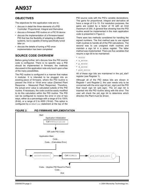
maximum of 255. A general flow showing how the <strong>PID</strong><br />
routine would be implemented in the main application<br />
code is presented in Figure 2.<br />
There were two methods considered for handling the<br />
signed numbers. The first method was to use signed<br />
math routines to handle all of the <strong>PID</strong> calculations. The<br />
second was to use unsigned math routines and<br />
maintain a sign bit in a status register. The latter<br />
method was implemented. There are five variables that<br />
require a sign bit to be maintained:<br />
• error<br />
• a_error<br />
• p_error<br />
• d_error<br />
• pid_error<br />
All of these sign bits are maintained in the pid_stat1<br />
register (see Register 1).<br />
Although all of the <strong>PID</strong> status bits are shown in<br />
Register 1 and Register 2, the user needs only to be<br />
concerned with the error sign bit (err_sign) and the <strong>PID</strong><br />
final result sign bit (pid_sign). The err_sign bit is<br />
inserted into the <strong>PID</strong> routine along with the error. The<br />
user will check the pid_sign bit to determine which<br />
direction the Plant must be driven.<br />
FIGURE 2:<br />
<strong>PID</strong> FIRMWARE IMPLEMENTATION<br />
Start<br />
Application Initialization<br />
Call <strong>PID</strong>Initialize<br />
ISR (with <strong>PID</strong> Code)<br />
Application Main<br />
Code...<br />
Code... (Calculates Error)<br />
error0:error1 Call <strong>PID</strong>Main pid_out0:pid_out2<br />
Code... (Applies <strong>PID</strong> Result to Plant)<br />
Code...<br />
End<br />
DS00937A-page 2<br />
© 2004 Microchip Technology Inc.