AN937, Implementing a PID Controller Using a PIC18 MCU
AN937, Implementing a PID Controller Using a PIC18 MCU
AN937, Implementing a PID Controller Using a PIC18 MCU

Create successful ePaper yourself
Turn your PDF publications into a flip-book with our unique Google optimized e-Paper software.
<strong>AN937</strong><br />
<strong>Implementing</strong> a <strong>PID</strong> <strong>Controller</strong> <strong>Using</strong> a <strong>PIC18</strong> <strong>MCU</strong><br />
Author:<br />
INTRODUCTION<br />
Chris Valenti<br />
Microchip Technology Inc.<br />
Continuous processes have been controlled by<br />
feedback loops since the late 1700’s. In 1788, James<br />
Watt used a flyball governor on his steam engine to<br />
regulate its speed. The Taylor Instrument Company<br />
implemented the first fully functional Proportional,<br />
Integral and Derivative (<strong>PID</strong>) controller in 1940.<br />
Although feedback control has come a long way since<br />
James Watt, the basic approach and system elements<br />
have not changed. There are several elements within a<br />
feedback system; for discussion purposes, we will use<br />
a home heating temperature control system as our<br />
model in the descriptions below.<br />
• Plant – The physical heating and cooling parts of<br />
the system.<br />
• Sensors – The devices (thermistors measuring<br />
temperature) that measure the variables within<br />
the Plant.<br />
• Setpoint – This is a value (i.e., 70 degrees),<br />
which is converted to a voltage that the process<br />
drives towards.<br />
• Error Signal – This is the difference between the<br />
response of the Plant and the desired response<br />
(Setpoint). In a house, the thermostat may be set<br />
to 70 degrees, but the temperature is actually<br />
65 degrees, therefore resulting in an error of<br />
5 degrees (Error = Setpoint – Measured).<br />
• Disturbances – These are unwanted inputs to<br />
the Plant, which can be common. A disturbance<br />
would be an open entry door allowing a gust<br />
of cold air to blow in, quickly dropping the<br />
temperature and causing the heat to come on.<br />
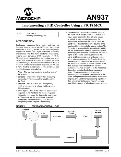
• <strong>Controller</strong> – Intentionally left for last, this is the<br />
most significant element of a control system. The<br />
<strong>Controller</strong> is responsible for several tasks and is<br />
the link that connects together all of the physical<br />
and nonphysical elements. It measures the output<br />
signal of the Plant’s Sensors, processes the<br />
signal and then derives an error based on the<br />
signal measurement and the Setpoint. Once the<br />
sensor data has been collected and processed,<br />
the result must be used to find <strong>PID</strong> values, which<br />
then must be sent out to the Plant for error<br />
correction. The rate at which all of this happens is<br />
dependent upon the <strong>Controller</strong>’s processing<br />
power. This may or may not be an issue<br />
depending on the response characteristic of the<br />
Plant. A temperature control system is much more<br />
forgiving on a <strong>Controller</strong>’s processing capabilities<br />
than a motor control system. Figure 1 shows a<br />
basic block diagram of a feedback control system.<br />
FIGURE 1:<br />
FEEDBACK CONTROL LOOP<br />
Setpoint<br />
Error<br />
<strong>Controller</strong><br />
Output<br />
Process<br />
Variable<br />
<strong>Controller</strong><br />
Plant<br />
+<br />
–<br />
Feedback<br />
© 2004 Microchip Technology Inc. DS00937A-page 1
<strong>AN937</strong><br />
OBJECTIVES<br />
The objectives for this application note are to:<br />
• discuss in detail the three elements of a <strong>PID</strong><br />
<strong>Controller</strong>: Proportional, Integral and Derivative<br />
• discuss a firmware <strong>PID</strong> routine on a <strong>PIC18</strong> device<br />
• discuss the implementation of a firmware-based<br />
<strong>PID</strong> that has the flexibility of adapting to different<br />
systems, but is capable of being specifically tuned<br />
later on<br />
• discuss the details of tuning a <strong>PID</strong> once<br />
implementation has been completed<br />
SOURCE CODE OVERVIEW<br />
Before going further, let’s discuss how the <strong>PID</strong> source<br />
code is configured. There is no specific way a <strong>PID</strong><br />
should be implemented in firmware; the methods<br />
discussed in this application note only touch upon a few<br />
of the many possibilities.<br />
The <strong>PID</strong> routine is configured in a manner that makes<br />
it modular. It is intended to be plugged into an<br />
existing piece of firmware, where the <strong>PID</strong> routine is<br />
passed the 8-bit or 16-bit error value (Desired Plant<br />
Response – Measured Plant Response). Therefore,<br />
the actual error value is calculated outside of the <strong>PID</strong><br />
routine. If necessary, the code could be easily modified<br />
to do this calculation within the <strong>PID</strong> routine. The <strong>PID</strong><br />
can be configured to receive the error in one of two<br />
ways, either as a percentage with a range of 0 to 100%<br />
(8-bit), or a range of 0 to 4000 (16-bit). This option is<br />
configured by a #define statement at the top of the<br />
<strong>PID</strong> source code with the <strong>PID</strong>’s variable declarations.<br />
The gains for proportional, integral and derivative all<br />
have a range of 0 to 15. For resolution purposes, the<br />
gains are scaled by a factor of 16 with an 8-bit<br />
maximum of 255. A general flow showing how the <strong>PID</strong><br />
routine would be implemented in the main application<br />
code is presented in Figure 2.<br />
There were two methods considered for handling the<br />
signed numbers. The first method was to use signed<br />
math routines to handle all of the <strong>PID</strong> calculations. The<br />
second was to use unsigned math routines and<br />
maintain a sign bit in a status register. The latter<br />
method was implemented. There are five variables that<br />
require a sign bit to be maintained:<br />
• error<br />
• a_error<br />
• p_error<br />
• d_error<br />
• pid_error<br />
All of these sign bits are maintained in the pid_stat1<br />
register (see Register 1).<br />
Although all of the <strong>PID</strong> status bits are shown in<br />
Register 1 and Register 2, the user needs only to be<br />
concerned with the error sign bit (err_sign) and the <strong>PID</strong><br />
final result sign bit (pid_sign). The err_sign bit is<br />
inserted into the <strong>PID</strong> routine along with the error. The<br />
user will check the pid_sign bit to determine which<br />
direction the Plant must be driven.<br />
FIGURE 2:<br />
<strong>PID</strong> FIRMWARE IMPLEMENTATION<br />
Start<br />
Application Initialization<br />
Call <strong>PID</strong>Initialize<br />
ISR (with <strong>PID</strong> Code)<br />
Application Main<br />
Code...<br />
Code... (Calculates Error)<br />
error0:error1 Call <strong>PID</strong>Main pid_out0:pid_out2<br />
Code... (Applies <strong>PID</strong> Result to Plant)<br />
Code...<br />
End<br />
DS00937A-page 2<br />
© 2004 Microchip Technology Inc.
<strong>AN937</strong><br />
Firmware Variables and Constants<br />
The list of firmware variables and constants and their<br />
definitions that are discussed in this application note<br />
are shown in Table 1.<br />
TABLE 1:<br />
FIRMWARE VARIABLES AND CONSTANTS<br />
Variable/Constant Type Definition<br />
error0:error1 Error Variable 16-bit variable, difference between the Setpoint and measured output of<br />
the Plant<br />
a_error0:a_error1 Error Variable 16-bit variable, accumulative error which is the sum of all past errors<br />
d_error0:d_error1 Error Variable 16-bit variable, difference between error0:error1 and<br />
p_error0:p_error1<br />
p_error0:p_error1 Error Variable 16-bit variable, value of the last error<br />
a_err_1_lim Error Variable 8-bit constant defining the accumulative error limits<br />
a_err_2_lim Error Variable 8-bit constant defining the accumulative error limits<br />
kd Gains 8-bit variable, derivative gain, max. = 15 (16 levels)<br />
ki Gains 8-bit variable, integral gain, max. = 15 (16 levels)<br />
kp Gains 8-bit variable, proportional gain, max. = 15 (16 levels)<br />
pid_stat1 Status Register 8-bit variable, status bit register (see Register 1)<br />
pid_stat2 Status Register 8-bit variable, status bit register (see Register 2)<br />
deriv0:deriv2 Terms 24-bit variable, value of the derivative term<br />
integ0:integ2 Terms 24-bit variable, value of the integral term<br />
pid_out0:pid_out2 Terms<br />
24-bit variable, final <strong>PID</strong> results<br />
prop0:prop2 Terms 24-bit variable, value of the proportional term<br />
timer1_hi Time Base 8-bit constant loaded into the TMR1H register<br />
timer1_lo Time Base 8-bit constant loaded into the TMR1L register<br />
Note: In 16-bit variables, the first variable is the Most Significant Byte (MSB), whereas the second variable is the<br />
Least Significant Byte (LSB). For example, in the variable error0:error1, error0 = MSB 8-bit and<br />
error1 = LSB 8-bit.<br />
In 24-bit variables, the first variable is the MSB, whereas the last variable is the LSB. For example, in the<br />
variable pid_out0:pid_out2, pid_out0 = MSB 8-bit and pid_out2 = LSB 8-bit.<br />
© 2004 Microchip Technology Inc. DS00937A-page 3
<strong>AN937</strong><br />
Data Registers<br />
The pid_stat1 and pid_stat2 Data registers contain the<br />
individual <strong>PID</strong> status bits. The following two registers<br />
provide brief bit descriptions and their associated<br />
values.<br />
REGISTER 1:<br />
pid_stat1 DATA REGISTER<br />
pid_sign d_err_sign mag p_err_sign a_err_sign err_sign a_err_zero err_zero<br />
bit 7 bit 0<br />
bit 7<br />
bit 6<br />
bit 5<br />
bit 4<br />
bit 3<br />
bit 2<br />
bit 1<br />
bit 0<br />
pid_sign: Indicates sign of final <strong>PID</strong> result<br />
1 = Result was positive<br />
0 = Result was negative<br />
d_err_sign: Indicates sign of the derivative term<br />
1 = Result was positive<br />
0 = Result was negative<br />
mag: Indicates which variable is greater in magnitude (AARGB or BARGB)<br />
1 = Result was AARGB<br />
0 = Result was BARGB<br />
p_err_sign: Indicates sign of the previous error<br />
1 = Result was positive<br />
0 = Result was negative<br />
a_err_sign: Indicates sign of the accumulative error<br />
1 = Result was positive<br />
0 = Result was negative<br />
err_sign: Indicates sign of the error (input into the <strong>PID</strong>)<br />
1 = Result was positive<br />
0 = Result was negative<br />
a_err_zero: Indicates if the accumulative error is equal to zero or non-zero<br />
1 = Result was zero<br />
0 = Result was non-zero<br />
err_zero: Indicates if the error is equal to zero or non-zero<br />
1 = Result was zero<br />
0 = Result was non-zero<br />
REGISTER 2:<br />
pid_stat2 DATA REGISTER<br />
— — — — — d_err_z — —<br />
bit 7 bit 0<br />
bit 7-3, 1-0 Unimplemented<br />
bit 2 d_err_z: Indicates if the data error is equal to zero<br />
1 = Result was zero<br />
0 = Result was non-zero<br />
DS00937A-page 4<br />
© 2004 Microchip Technology Inc.
<strong>AN937</strong><br />
<strong>PID</strong> Routine Flowcharts<br />
Flowcharts for the <strong>PID</strong> main routine and the <strong>PID</strong><br />
Interrupt Service Routine (ISR) functions are shown in<br />
Figure 3 and Figure 4 (see following pages).<br />
The <strong>PID</strong> main routine is intended to be called from<br />
the main application code that updates the<br />
error0:error1 variable, as well as the pid_stat1 error<br />
sign bit. Once in the <strong>PID</strong> main routine, the <strong>PID</strong> value will<br />
be calculated and put into the pid_out0:pid_out2<br />
variable, with its sign bit in pid_stat1. The value in<br />
pid_out0:pid_out2 is converted by the application<br />
code to the correct value so that it can be applied to the<br />
Plant.<br />
The <strong>PID</strong> ISR is configured for the <strong>PIC18</strong> device’s high<br />
priority interrupt at location 0x0008. The instructions<br />
within this ISR can be placed into an existing ISR, or<br />
kept as is and plugged into the application.<br />
FIGURE 3:<br />
error0:error1<br />
MAIN <strong>PID</strong> ROUTINE (<strong>PID</strong>Main)<br />
The error is passed from the main<br />
application code to the <strong>PID</strong> routine,<br />
along with the error sign bit in<br />
pid_stat1<br />
error = 0?<br />
NO<br />
YES<br />
<strong>PID</strong> Action is not<br />
Required, Return to<br />
Main Application<br />
Code<br />
Calculate<br />
Proportional Term<br />
Proportional Gain * error0:error1<br />
a_error0:a_error1<br />
Calculate Integral<br />
Term<br />
Integral Gain * a_error0:a_error1<br />
Calculate<br />
Derivative Term<br />
Derivative Gain * d_error0:d_error1<br />
Proceed to<br />
GetPidResult<br />
Prop + Integ<br />
The final <strong>PID</strong> result is sent to<br />
the main application code,<br />
along with its sign located in<br />
pid_stat1<br />
(Prop + Integ) +<br />
Deriv<br />
Scale Down<br />
(Prop + Integ +<br />
Deriv)<br />
Place Final <strong>PID</strong> Value in<br />
pid_out0:pid_out2<br />
pid_out0:pid_out2<br />
© 2004 Microchip Technology Inc. DS00937A-page 5
<strong>AN937</strong><br />
FIGURE 4:<br />
<strong>PID</strong> INTERRUPT ROUTINE (PidInterrupt)<br />
High Priority<br />
Interrupt Occurred<br />
Has a Timer 1<br />
interrupt occurred?<br />
NO<br />
RETFIE<br />
YES<br />
error = 0?<br />
YES<br />
RETURN<br />
NO<br />
Context Saves<br />
Call GetA_Error<br />
error + a_error a_error = 0?<br />
NO<br />
a_error limit<br />
exceeded?<br />
YES<br />
YES<br />
NO<br />
RETURN<br />
Restore<br />
a_error<br />
Limit<br />
Math Variables (1) d_error = 0?<br />
deriv_Count = 0? YES<br />
Call<br />
GetDeltaError<br />
YES<br />
Set d_err_z bit<br />
NO<br />
NO<br />
Reload<br />
TMR1H:TMR1L,<br />
Clear T1 Flag<br />
RETURN<br />
Restore Math<br />
Variables (1)<br />
RETURN<br />
Note 1:<br />
These instructions are options; they are dependant upon how the ISR is configured. The ISR code<br />
referenced in this application note is set up with context save/restore and is within the main<br />
application code ISR.<br />
DS00937A-page 6<br />
© 2004 Microchip Technology Inc.
<strong>AN937</strong><br />
Proportional<br />
The proportional term is the simplest of the three and is<br />
also the most commonly found control technique in a<br />
feedback system. The proportional gain (kp) is<br />
multiplied by the error. In this application note, the error<br />
is a 16-bit value, error0:error1. The amount of<br />
correction applied to the system is directly proportional<br />
to the error. As the gain increases, the applied correction<br />
to the Plant becomes more aggressive. This type<br />
of <strong>Controller</strong> is common for driving the error to a small,<br />
but non-zero value, leaving a steady state error. This is<br />
the reason for proportional control not being enough in<br />
some systems, thereby requiring integral and derivative<br />
control to come into play, separately or together<br />
(i.e., PI, PD or <strong>PID</strong> <strong>Controller</strong>).<br />
IMPLEMENTATION<br />
As mentioned earlier, the proportional is the simplest<br />
term. The error is multiplied by the proportional gain,<br />
error0:error1 * kp. This is accomplished by the<br />
16 * 16 multiplication routine. The result is stored in the<br />
24-bit variable, prop0:prop2. This value will be used<br />
later in the code to calculate the overall value needed<br />
to go to the Plant.<br />
EQUATION 1:<br />
Integral<br />
PROPORTIONAL TERM<br />
prop0:prop2 = kp * error0:error1<br />
Unlike proportional control, which looks at the present<br />
error, integral control looks at past errors. Given this,<br />
the accumulative error (sum of all past errors) is used<br />
to calculate the integral term, but at fixed time intervals.<br />
Basically, every time the fixed interval expires, the<br />
current error at that moment is added to the a_error<br />
variable. A temperature system would require a longer<br />
sample period than a motor system because of the<br />
sluggish response in a temperature controlled environment.<br />
If the integral sample period was too fast in the<br />
temperature system, the accumulative error would add<br />
too quickly to give the system a chance to respond,<br />
thereby not allowing it to ever stabilize. Another<br />
element in integral control to consider is ‘wind-up’.<br />
Wind-up occurs when the accumulative error keeps<br />
increasing because the Plant output is saturated. This<br />
event can be avoided by setting limits to the accumulative<br />
error. It can also be eliminated by not executing the<br />
integral term when the Plant output is saturated.<br />
Another characteristic is excessive gain, that can<br />
create an unstable condition within the system, causing<br />
it to oscillate. The integral gain must be thoroughly<br />
tested for all possible situations to find the best overall<br />
value. In conclusion, as the accumulative error<br />
increases, the integral term has a greater effect on the<br />
Plant. In a sluggish system, this could dominate the<br />
value that is sent to the Plant.<br />
IMPLEMENTATION<br />
To obtain the integral term, the accumulated error<br />
must be retrieved. The accumulated error<br />
(a_error0:a_error2) is the sum of past errors. For<br />
this reason, the integral is known for looking at a<br />
system’s history for correction. Refer to Table 2 for<br />
details on how a_error is accumulated.<br />
Each time the <strong>PID</strong> routine receives an error, it may or<br />
may not be added to the accumulated error variable.<br />
This is dependant upon the Timer1 overflow rate. If<br />
Timer1 overflowed, then the error at that moment will<br />
be added to the accumulated error variable. The<br />
Timer1 overflow rate is interrupt driven and is configured<br />
as a high priority interrupt. The TMR1H:TMR1L<br />
registers are loaded with values defined by the<br />
constants, timer1_hi and timer1_lo. The values<br />
for these constants should be based on the Plant’s<br />
response. The accumulated error will be multiplied by<br />
the integral gain, a_error0:a_error2 * ki and the<br />
result is stored in integ0:integ2.<br />
TABLE 2: a_error ACCUMULATION EXAMPLE<br />
Time Error Timer1 Overflow Accumulated Error<br />
t = n 10% No x%<br />
t = n + 1 8% No x%<br />
t = n + 2 12% Yes x + 12%<br />
t = n + 3 9% No (x% + 12%)<br />
t = n + 4 6% No (x% + 12%)<br />
t = n + 5 4% Yes (x% + 12%) + 4%<br />
t = n + ...<br />
© 2004 Microchip Technology Inc. DS00937A-page 7
<strong>AN937</strong><br />
To avoid integral wind-up, accumulative error limits<br />
were installed (a_err_1_Lim:a_err_2_Lim). When<br />
the accumulative error is calculated, the result is compared<br />
against the limit variables. If the calculated value<br />
exceeds the limits, the accumulative error is made<br />
equal to the value that is determined by the user in the<br />
variable definition at the beginning of the code.<br />
EQUATION 2:<br />
INTEGRAL TERM<br />
integ0:integ2 = ki * a_error0:a_error1 (a_error0:a_error1 = error0:error1 + error0:error1 + …error0:error1)<br />
Derivative<br />
As previously mentioned, the proportional term works<br />
on the present error, the integral term works on past<br />
errors and the derivative term works on the present and<br />
past error to forecast a future response of the system.<br />
The derivative term makes an adjustment based on the<br />
rate at which the Plant output is changing from its<br />
Setpoint. A notable characteristic in this type of control<br />
is when the error is constant, or at the maximum limit,<br />
the effect is minimal. There are some systems where<br />
proportional and/or integral do not provide enough<br />
control. In these systems, adding in the derivative term<br />
completes the control requirements.<br />
IMPLEMENTATION<br />
The derivative term is calculated in similar fashion to<br />
the integral term. Considering that the derivative term<br />
is based on the rate at which the system is changing,<br />
the derivative routine calculates d_error. This is the<br />
difference between the current error and the previous<br />
error. The rate at which this calculation takes place is<br />
dependant upon the Timer1 overflow. The derivative<br />
term can be extremely aggressive when it is acting on<br />
the error of the system. An alternative to this is to calculate<br />
the derivative term from the output of the system<br />
and not the error. In this application note, the error will<br />
be used. To keep the derivative term from being too<br />
aggressive, a derivative counter variable has been<br />
installed. This variable allows d_error to be calculated<br />
once for an x number of Timer1 overflows (unlike the<br />
accumulated error, which is calculated every Timer1<br />
overflow).<br />
To get the derivative term, the previous error is subtracted<br />
from the current error (d_errro0:d_error1 =<br />
error0:error – p_error0:p_error1). The difference<br />
is then multiplied by the derivative gain (kd) and<br />
this result is placed in deriv0:deriv2, which is<br />
added with the proportional and integral terms.<br />
Tuning<br />
There are several different ways to tune a <strong>PID</strong><br />
<strong>Controller</strong> for system optimization. The code in this<br />
application note is loosely defined, giving it the<br />
flexibility to be tuned for a specific application (i.e.,<br />
motor control, temperature, actuator, etc.).<br />
Tuning a <strong>PID</strong> <strong>Controller</strong> can be somewhat difficult and<br />
time consuming and should be completed in a<br />
systematic fashion.<br />
1. Run the system in an open loop and measure its<br />
response over time. Based on the measured<br />
response, you will get an idea for which <strong>PID</strong><br />
term is needed most.<br />
2. Determine the application requirements: Plant<br />
response time, which <strong>PID</strong> term will have the<br />
most affect and accumulative error limits.<br />
3. Determine how often the a_error and<br />
d_error terms should be calculated; this will<br />
dictate the values loaded into the Timer1 and<br />
derivative counter registers.<br />
In the current configuration, d_error is calculated<br />
once for every a_error calculation. Should this be<br />
less or more, or vice versa? Finally, once these<br />
variables are decided, the <strong>PID</strong> gains can be<br />
experimented with. Start with the smallest gains (i.e.,<br />
kp =1*16, ki =1*16, kd = 1 * 16), slowly<br />
increasing these values until the desired output is<br />
reached. With a few code modifications, it is possible to<br />
make the <strong>Controller</strong> a proportional only <strong>Controller</strong> and<br />
tune this to an optimal value. Then it is possible to add<br />
the other terms one at a time, optimizing each time.<br />
EQUATION 3:<br />
DERIVATIVE TERM<br />
deriv0:deriv2 = kd * d_error0:d_error1 (d_error0:d_error1 = error0:error – p_error:p_error1)<br />
DS00937A-page 8<br />
© 2004 Microchip Technology Inc.
<strong>AN937</strong><br />
The system response of a temperature controlled<br />
environment is shown in Figures 5 through 7. Figure 5<br />
shows the graphic response for a proportional only<br />
feedback loop. As shown, none of the gain values can<br />
reach the input signal and maintain that level. All four<br />
gain values have settled at a non-zero value, as<br />
previously discussed.<br />
FIGURE 5:<br />
PROPORTIONAL ONLY GRAPHIC RESPONSE<br />
1.4<br />
1.2<br />
1<br />
Temp<br />
0.8<br />
0.6<br />
0.4<br />
0.2<br />
0<br />
Pgain = 1<br />
Pgain = 2<br />
Pgain = 5<br />
Pgain = 10<br />
Input<br />
0 0.5 1 1.5 2 2.5 3 3.5 4<br />
Time<br />
© 2004 Microchip Technology Inc. DS00937A-page 9
<strong>AN937</strong><br />
Figure 6 shows the graphic response of a Proportional/<br />
Integral (PI) <strong>Controller</strong>. The high integral gain<br />
dominates the response (see line with diamond<br />
shapes).<br />
With a tuned proportional and integral gain, the system<br />
does settle to its Setpoint, which is why PI control is<br />
adequate in many systems. The disadvantage is the<br />
time required for it to settle (t = 3), which brings us to<br />
<strong>PID</strong> control.<br />
FIGURE 6:<br />
PROPORTIONAL/INTEGRAL (PI) CONTROLLER GRAPHIC RESPONSE<br />
1.4<br />
1.2<br />
1<br />
Temperature<br />
0.8<br />
0.6<br />
0.4<br />
0.2<br />
0<br />
P = 2, I = 0.1<br />
P = 2, I = 0.05<br />
P = 2, I = 0.02<br />
P = 1, I = 0.02<br />
Input<br />
0 1 2 3 4 5 6<br />
Time<br />
DS00937A-page 10<br />
© 2004 Microchip Technology Inc.
<strong>AN937</strong><br />
Figure 7 shows the graphic response of a <strong>PID</strong><br />
<strong>Controller</strong>. This graph is very similar to the PI graph<br />
(Figure 6), except that the <strong>PID</strong> control takes half as<br />
long as the PI control to settle (t = 1.5) as the Setpoint.<br />
FIGURE 7:<br />
<strong>PID</strong> CONTROLLER GRAPHIC RESPONSE<br />
1.4<br />
1.2<br />
1<br />
Temperature<br />
0.8<br />
0.6<br />
0.4<br />
0.2<br />
P = 20, I = 0.5, D = 100<br />
P = 20, I = 0.1, D = 100<br />
P = 10, I = 0.1, D = 50<br />
P = 5, I = 0.1, D = 50<br />
Input<br />
0<br />
0 0.2 0.4 0.6 0.8 1 1.2 1.4 1.6 1.8 2<br />
Time<br />
<strong>PID</strong> Output<br />
The <strong>PID</strong> output is calculated after the proportional,<br />
integral and derivative terms have been determined. In<br />
addition to this calculation is the pid_sign bit, which the<br />
user must check to decide which direction the Plant will<br />
be driven. This bit is located in pid_stat1. The sum of all<br />
these terms is stored in pid_out0:pid_out2.<br />
EQUATION 4:<br />
<strong>PID</strong> ROUTINE<br />
<strong>PID</strong> Output = prop0:prop2 + integ0:integ2 + deriv0:deriv2<br />
© 2004 Microchip Technology Inc. DS00937A-page 11
<strong>AN937</strong><br />
CONCLUSION<br />
As mentioned in the introduction, the <strong>Controller</strong>’s<br />
processing capabilities will dictate the system’s ability<br />
to respond to the error. Table 3 shows a list of <strong>PID</strong> functions,<br />
each with the amount of instruction cycles and<br />
time required. In cases where the Plant response is<br />
sluggish, it may be possible to decrease the processor<br />
speed and save on power, but still be able to execute<br />
the <strong>PID</strong> routine in acceptable time.<br />
TABLE 3:<br />
<strong>PID</strong> FUNCTIONS<br />
Function Instruction Cycles Elapsed Time (µS) (TCY at 40 MHz)<br />
<strong>PID</strong> Main 437 43.7<br />
Proportional 50 5.0<br />
Integral 52 5.2<br />
Derivative 52 5.2<br />
GetPidResult 270 27<br />
GetA_Error 70 7.0<br />
<strong>PID</strong> Interrupt 184 18.4<br />
The measurements shown in Table 3 can vary,<br />
depending on the size of the error and how much of the<br />
math routines will be used. The measurements also<br />
reflect an error of 6% sent to the <strong>PID</strong> routine.<br />
After the code development for this application note<br />
was completed, the <strong>PID</strong> routine was implemented on<br />
the <strong>PIC18</strong>F4431 Motor Control board (PICDEM MC).<br />
For the initial start of the motor, the <strong>PID</strong> gains were:<br />
kp = 96, ki = 80 and kd = 16. These were scaled<br />
values. After starting the motor and running it close to<br />
its set speed, the integral gain was changed to 144.<br />
The accumulated error was calculated every<br />
millisecond, initiated by a Timer1 overflow. The delta<br />
error (d_error) was calculated every 4 ms (derivative<br />
counter = 4).<br />
DS00937A-page 12<br />
© 2004 Microchip Technology Inc.
<strong>AN937</strong><br />
APPENDIX A:<br />
SOURCE CODE<br />
The complete source code, including the <strong>PID</strong><br />
Application Maestro module, any demo applications<br />
and necessary support files, are available for download<br />
as a single archive file from the Microchip corporate<br />
web site at:<br />
www.microchip.com<br />
© 2004 Microchip Technology Inc. DS00937A-page 13
<strong>AN937</strong><br />
NOTES:<br />
DS00937A-page 14<br />
© 2004 Microchip Technology Inc.
Note the following details of the code protection feature on Microchip devices:<br />
• Microchip products meet the specification contained in their particular Microchip Data Sheet.<br />
• Microchip believes that its family of products is one of the most secure families of its kind on the market today, when used in the<br />
intended manner and under normal conditions.<br />
• There are dishonest and possibly illegal methods used to breach the code protection feature. All of these methods, to our<br />
knowledge, require using the Microchip products in a manner outside the operating specifications contained in Microchip’s Data<br />
Sheets. Most likely, the person doing so is engaged in theft of intellectual property.<br />
• Microchip is willing to work with the customer who is concerned about the integrity of their code.<br />
• Neither Microchip nor any other semiconductor manufacturer can guarantee the security of their code. Code protection does not<br />
mean that we are guaranteeing the product as “unbreakable.”<br />
Code protection is constantly evolving. We at Microchip are committed to continuously improving the code protection features of our<br />
products. Attempts to break Microchip’s code protection feature may be a violation of the Digital Millennium Copyright Act. If such acts<br />
allow unauthorized access to your software or other copyrighted work, you may have a right to sue for relief under that Act.<br />
Information contained in this publication regarding device<br />
applications and the like is intended through suggestion only<br />
and may be superseded by updates. It is your responsibility to<br />
ensure that your application meets with your specifications.<br />
No representation or warranty is given and no liability is<br />
assumed by Microchip Technology Incorporated with respect<br />
to the accuracy or use of such information, or infringement of<br />
patents or other intellectual property rights arising from such<br />
use or otherwise. Use of Microchip’s products as critical<br />
components in life support systems is not authorized except<br />
with express written approval by Microchip. No licenses are<br />
conveyed, implicitly or otherwise, under any intellectual<br />
property rights.<br />
Trademarks<br />
The Microchip name and logo, the Microchip logo, Accuron,<br />
dsPIC, KEELOQ, microID, MPLAB, PIC, PICmicro, PICSTART,<br />
PRO MATE, PowerSmart, rfPIC, and SmartShunt are<br />
registered trademarks of Microchip Technology Incorporated<br />
in the U.S.A. and other countries.<br />
AmpLab, FilterLab, MXDEV, MXLAB, PICMASTER, SEEVAL,<br />
SmartSensor and The Embedded Control Solutions Company<br />
are registered trademarks of Microchip Technology<br />
Incorporated in the U.S.A.<br />
Analog-for-the-Digital Age, Application Maestro, dsPICDEM,<br />
dsPICDEM.net, dsPICworks, ECAN, ECONOMONITOR,<br />
FanSense, FlexROM, fuzzyLAB, In-Circuit Serial<br />
Programming, ICSP, ICEPIC, Migratable Memory, MPASM,<br />
MPLIB, MPLINK, MPSIM, PICkit, PICDEM, PICDEM.net,<br />
PICLAB, PICtail, PowerCal, PowerInfo, PowerMate,<br />
PowerTool, rfLAB, rfPICDEM, Select Mode, Smart Serial,<br />
SmartTel and Total Endurance are trademarks of Microchip<br />
Technology Incorporated in the U.S.A. and other countries.<br />
SQTP is a service mark of Microchip Technology Incorporated<br />
in the U.S.A.<br />
All other trademarks mentioned herein are property of their<br />
respective companies.<br />
© 2004, Microchip Technology Incorporated, Printed in the<br />
U.S.A., All Rights Reserved.<br />
Printed on recycled paper.<br />
Microchip received ISO/TS-16949:2002 quality system certification for<br />
its worldwide headquarters, design and wafer fabrication facilities in<br />
Chandler and Tempe, Arizona and Mountain View, California in<br />
October 2003. The Company’s quality system processes and<br />
procedures are for its PICmicro ® 8-bit <strong>MCU</strong>s, KEELOQ ® code hopping<br />
devices, Serial EEPROMs, microperipherals, nonvolatile memory and<br />
analog products. In addition, Microchip’s quality system for the design<br />
and manufacture of development systems is ISO 9001:2000 certified.<br />
© 2004 Microchip Technology Inc. DS00937A-page 15
Worldwide Sales and Service<br />
AMERICAS<br />
Corporate Office<br />
2355 West Chandler Blvd.<br />
Chandler, AZ 85224-6199<br />
Tel: 480-792-7200<br />
Fax: 480-792-7277<br />
Technical Support: 480-792-7627<br />
Web Address: www.microchip.com<br />
Atlanta<br />
3780 Mansell Road, Suite 130<br />
Alpharetta, GA 30022<br />
Tel: 770-640-0034<br />
Fax: 770-640-0307<br />
Boston<br />
2 Lan Drive, Suite 120<br />
Westford, MA 01886<br />
Tel: 978-692-3848<br />
Fax: 978-692-3821<br />
Chicago<br />
333 Pierce Road, Suite 180<br />
Itasca, IL 60143<br />
Tel: 630-285-0071<br />
Fax: 630-285-0075<br />
Dallas<br />
4570 Westgrove Drive, Suite 160<br />
Addison, TX 75001<br />
Tel: 972-818-7423<br />
Fax: 972-818-2924<br />
Detroit<br />
Tri-Atria Office Building<br />
32255 Northwestern Highway, Suite 190<br />
Farmington Hills, MI 48334<br />
Tel: 248-538-2250<br />
Fax: 248-538-2260<br />
Kokomo<br />
2767 S. Albright Road<br />
Kokomo, IN 46902<br />
Tel: 765-864-8360<br />
Fax: 765-864-8387<br />
Los Angeles<br />
18201 Von Karman, Suite 1090<br />
Irvine, CA 92612<br />
Tel: 949-263-1888<br />
Fax: 949-263-1338<br />
San Jose<br />
1300 Terra Bella Avenue<br />
Mountain View, CA 94043<br />
Tel: 650-215-1444<br />
Fax: 650-961-0286<br />
Toronto<br />
6285 Northam Drive, Suite 108<br />
Mississauga, Ontario L4V 1X5, Canada<br />
Tel: 905-673-0699<br />
Fax: 905-673-6509<br />
ASIA/PACIFIC<br />
Australia<br />
Suite 22, 41 Rawson Street<br />
Epping 2121, NSW<br />
Australia<br />
Tel: 61-2-9868-6733<br />
Fax: 61-2-9868-6755<br />
China - Beijing<br />
Unit 706B<br />
Wan Tai Bei Hai Bldg.<br />
No. 6 Chaoyangmen Bei Str.<br />
Beijing, 100027, China<br />
Tel: 86-10-85282100<br />
Fax: 86-10-85282104<br />
China - Chengdu<br />
Rm. 2401-2402, 24th Floor,<br />
Ming Xing Financial Tower<br />
No. 88 TIDU Street<br />
Chengdu 610016, China<br />
Tel: 86-28-86766200<br />
Fax: 86-28-86766599<br />
China - Fuzhou<br />
Unit 28F, World Trade Plaza<br />
No. 71 Wusi Road<br />
Fuzhou 350001, China<br />
Tel: 86-591-7503506<br />
Fax: 86-591-7503521<br />
China - Hong Kong SAR<br />
Unit 901-6, Tower 2, Metroplaza<br />
223 Hing Fong Road<br />
Kwai Fong, N.T., Hong Kong<br />
Tel: 852-2401-1200<br />
Fax: 852-2401-3431<br />
China - Shanghai<br />
Room 701, Bldg. B<br />
Far East International Plaza<br />
No. 317 Xian Xia Road<br />
Shanghai, 200051<br />
Tel: 86-21-6275-5700<br />
Fax: 86-21-6275-5060<br />
China - Shenzhen<br />
Rm. 1812, 18/F, Building A, United Plaza<br />
No. 5022 Binhe Road, Futian District<br />
Shenzhen 518033, China<br />
Tel: 86-755-82901380<br />
Fax: 86-755-8295-1393<br />
China - Shunde<br />
Room 401, Hongjian Building, No. 2<br />
Fengxiangnan Road, Ronggui Town, Shunde<br />
District, Foshan City, Guangdong 528303, China<br />
Tel: 86-757-28395507 Fax: 86-757-28395571<br />
China - Qingdao<br />
Rm. B505A, Fullhope Plaza,<br />
No. 12 Hong Kong Central Rd.<br />
Qingdao 266071, China<br />
Tel: 86-532-5027355 Fax: 86-532-5027205<br />
India<br />
Divyasree Chambers<br />
1 Floor, Wing A (A3/A4)<br />
No. 11, O’Shaugnessey Road<br />
Bangalore, 560 025, India<br />
Tel: 91-80-22290061 Fax: 91-80-22290062<br />
Japan<br />
Benex S-1 6F<br />
3-18-20, Shinyokohama<br />
Kohoku-Ku, Yokohama-shi<br />
Kanagawa, 222-0033, Japan<br />
Tel: 81-45-471- 6166 Fax: 81-45-471-6122<br />
Korea<br />
168-1, Youngbo Bldg. 3 Floor<br />
Samsung-Dong, Kangnam-Ku<br />
Seoul, Korea 135-882<br />
Tel: 82-2-554-7200 Fax: 82-2-558-5932 or<br />
82-2-558-5934<br />
Singapore<br />
200 Middle Road<br />
#07-02 Prime Centre<br />
Singapore, 188980<br />
Tel: 65-6334-8870 Fax: 65-6334-8850<br />
Taiwan<br />
Kaohsiung Branch<br />
30F - 1 No. 8<br />
Min Chuan 2nd Road<br />
Kaohsiung 806, Taiwan<br />
Tel: 886-7-536-4818<br />
Fax: 886-7-536-4803<br />
Taiwan<br />
Taiwan Branch<br />
11F-3, No. 207<br />
Tung Hua North Road<br />
Taipei, 105, Taiwan<br />
Tel: 886-2-2717-7175 Fax: 886-2-2545-0139<br />
EUROPE<br />
Austria<br />
Durisolstrasse 2<br />
A-4600 Wels<br />
Austria<br />
Tel: 43-7242-2244-399<br />
Fax: 43-7242-2244-393<br />
Denmark<br />
Regus Business Centre<br />
Lautrup hoj 1-3<br />
Ballerup DK-2750 Denmark<br />
Tel: 45-4420-9895 Fax: 45-4420-9910<br />
France<br />
Parc d’Activite du Moulin de Massy<br />
43 Rue du Saule Trapu<br />
Batiment A - ler Etage<br />
91300 Massy, France<br />
Tel: 33-1-69-53-63-20<br />
Fax: 33-1-69-30-90-79<br />
Germany<br />
Steinheilstrasse 10<br />
D-85737 Ismaning, Germany<br />
Tel: 49-89-627-144-0<br />
Fax: 49-89-627-144-44<br />
Italy<br />
Via Quasimodo, 12<br />
20025 Legnano (MI)<br />
Milan, Italy<br />
Tel: 39-0331-742611<br />
Fax: 39-0331-466781<br />
Netherlands<br />
Waegenburghtplein 4<br />
NL-5152 JR, Drunen, Netherlands<br />
Tel: 31-416-690399<br />
Fax: 31-416-690340<br />
United Kingdom<br />
505 Eskdale Road<br />
Winnersh Triangle<br />
Wokingham<br />
Berkshire, England RG41 5TU<br />
Tel: 44-118-921-5869<br />
Fax: 44-118-921-5820<br />
05/28/04<br />
DS00937A-page 16<br />
© 2004 Microchip Technology Inc.