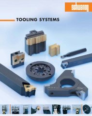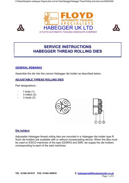
HABEGGER UK LTD - Floyd Automatic Tooling Ltd
HABEGGER UK LTD - Floyd Automatic Tooling Ltd
HABEGGER UK LTD - Floyd Automatic Tooling Ltd

Create successful ePaper yourself
Turn your PDF publications into a flip-book with our unique Google optimized e-Paper software.
H:\Shared\Suppliers catalogues Original plists and tech files\Habegger\Habegger Thread Rolling Instructions.doc/06/05/2005<br />
<strong>HABEGGER</strong> <strong>UK</strong> <strong>LTD</strong><br />
A FLOYD AUTOMATIC TOOLING ASSOCIATE COMPANY<br />
SERVICE INSTRUCTIONS<br />
<strong>HABEGGER</strong> THREAD ROLLING DIES<br />
GENERAL REMARKS<br />
Assemble the die into the correct Habegger die holder as described below.<br />
ADJUSTABLE THREAD ROLLING DIES<br />
Part designations :<br />
- 1 body (1)<br />
- 3 rollers (2)<br />
- 3 studs (3)<br />
Die holders<br />
Adjustable Habegger thread rolling dies are mounted in a Habegger die holder type R.<br />
Such die holders are available with or without compensating device. When the dies must<br />
be used on ESCO machines of the type D2GR43 and D6R, we supply the die holders<br />
corresponding to each of the said machines.<br />
TEL :01462 491919 FAX: 01462 490835 E: habeggeruk@floydautomatic.co.uk<br />
Page 1 of 8
H:\Shared\Suppliers catalogues Original plists and tech files\Habegger\Habegger Thread Rolling Instructions.doc/06/05/2005<br />
Habegger die holders type R<br />
Part designations :<br />
- 1 body (1)<br />
- 1 counter-nut (2)<br />
- 1 nut (3)<br />
Setting instructions :<br />
a) After having placed the adjustable thread rolling die on the die holder, tighten<br />
the nut (3) until it just tightens against the die. Loosen it slightly. Then,<br />
Lock the counter-nut (2) so that the die remains free. Make sure that it is not too<br />
tight from the beginning.<br />
b) The outside diameter is adjusted by modifying the turned diameter.<br />
c) The effective diameter is modified by adjusting the die nut (3)<br />
d) Of course, by modifying the dies adjustment, the outside diameter will also be<br />
altered.<br />
e) Both adjustments must be combined so that a small flat remains on top of the<br />
thread.<br />
Habegger die holders type R with compensating system<br />
Part designations:<br />
- 1 screw (7)<br />
- 1 sleeve washer (6)<br />
- 1 compensating spring (5)<br />
- 1 sleeve (4)<br />
- 1shaft-body (1)<br />
- 1 counter-nut (2)<br />
- 1 nut (3)<br />
When the thread rolling dies are used on fixed headstock turning machines or on CNC<br />
machines, a die holder with compensating system must be chosen. This Habegger system<br />
permits to compensate the feed differences between the die (according to the pitch) and<br />
the machine.<br />
At the engagement and during the whole threading operation, the machines' feed will be<br />
slightly lower than the pitch/rotation ratio. The pitch of the thread is generated solely by<br />
the die. The return spring permits this compensation. The working feed is calculated as<br />
follows: pitch x 0.98.<br />
TEL :01462 491919 FAX: 01462 490835 E: habeggeruk@floydautomatic.co.uk<br />
Page 2 of 8
H:\Shared\Suppliers catalogues Original plists and tech files\Habegger\Habegger Thread Rolling Instructions.doc/06/05/2005<br />
Habegger die holders for ESCO D2GR43 and D6R<br />
a) ESCO D2GR43: - 1 sleeve (1)<br />
- 1 plate (2)<br />
- 1 nut (3)<br />
b) ESCO D6R: - 1 plate (2)<br />
- 1 nut (3)<br />
Adjustment is effected in the same way as for Habegger die holders type R, but the locking<br />
of the nut is obtained by means of two radial screws instead of a counter-nut.<br />
NON-ADJUSTABLE THREAD ROLLING DIES<br />
Part designations:<br />
- 1 body (1)<br />
- 3 rollers (2)<br />
- 3 studs (3)<br />
These non-adjustable thread rolling dies are supplied for a diameter determined by the<br />
tolerances of the work piece thread. The tolerances and the material must be indicated<br />
at order. When working, the diameter of the dies will slightly increase. It is therefore<br />
advised to choose dies to the minimum of the tolerances.<br />
Ex : work piece : 0.90+0/-0.02<br />
die : 0.885<br />
TEL :01462 491919 FAX: 01462 490835 E: habeggeruk@floydautomatic.co.uk<br />
Page 3 of 8
H:\Shared\Suppliers catalogues Original plists and tech files\Habegger\Habegger Thread Rolling Instructions.doc/06/05/2005<br />
Die holders<br />
Non-adjustable thread rolling dies are assembled on the machines with the help of 3 types<br />
of die holders: the types N, F and V (see general catalogue).<br />
Habegger die holders type N<br />
Part designations:<br />
- 1 shaft (1)<br />
- 1 nut (2)<br />
- 1 head (3)<br />
This construction permits to dismantle the head (3) with its nut (2) and the die, without<br />
loosening the shaft (1). Thus, errors due to an eventual inattention after an exchange of<br />
dies will be avoided. It makes cleaning outside of the machine easier.<br />
Habegger die holders type F<br />
These die holders are made of a single piece. They take up dies that are hold by means of<br />
a thread. A guiding diameter gives the correct position.<br />
There are special die holders for left hand dies (L dies).<br />
Habegger die holders type V<br />
Part designations:<br />
- 1 die holder (1)<br />
- 3 fixations crews (2)<br />
These die holders are in single piece. They take dies maintained by 3 front screws. A<br />
guiding diameter gives the correct position.<br />
These die holder are mainly used on multi-spindle machines.<br />
Note: Some non-adjustable dies may also be assembled on R-type die holders.<br />
TEL :01462 491919 FAX: 01462 490835 E: habeggeruk@floydautomatic.co.uk<br />
Page 4 of 8
H:\Shared\Suppliers catalogues Original plists and tech files\Habegger\Habegger Thread Rolling Instructions.doc/06/05/2005<br />
1 Thread rolling with Habegger rolling dies needs the same ratio as for cutting dies.<br />
2 The peripheral speed of the work piece will be between 20 - 50 m/min.<br />
3 To have an easier engagement of the rolling die on the work piece, it is<br />
necessary to foresee an angle of 15 to 20° at the axis. The start effort is then<br />
reduced. The same angle must be foreseen at the end of the thread if the work<br />
piece shows a groove. The more the angle is long, the more the conditions get better.<br />
4 The blank turning of the work piece will be done as per indicative chart below:<br />
Thread rolling die: M 0.35 0.40 0.50 0.60 0.70 0.80 0.90 1.00 1.10<br />
Diameter "D”: 0.27 0.31 0.39 0.48 0.57 0.65 0.74 0.80 0.90<br />
Thread rolling die: M 1.20 1.30 1.40 1.50 1.60 1.70 1.80 2.00 2.20<br />
Diameter "D”: 1.00 1.05 1.15 1.25 1.30 1.40 1.50 1.60 1.75<br />
Thread rolling die: M 2.50 3.00 3.50 4.00 4.50 5.00 6.00 8.00<br />
Diameter "D”: 2.05 2.50 2.90 3.35 3.80 4.25 5.10 6.95<br />
This blank diameter will be increased progressively, until a slight flat remains on top of the<br />
thread. This flat must always be kept to avoid filling up with material or even spoiling the<br />
die.<br />
5 If it should fill up in spite of this precaution, proceed as follows:<br />
1) Chase the stud out with a stud-driver, pushing the die on a 3-jaw<br />
mandrel on a bench, but without clamping it.<br />
2) Take away the material in the die.<br />
3) Put back the roller in its place and chase the stud in. Take care that<br />
the roller revolves freely.<br />
Thread produced with correct Thread produced with Thread produced with Pre-roll<br />
Pre-roll diameter Pre-roll diameter too large diameter too small<br />
TEL :01462 491919 FAX: 01462 490835 E: habeggeruk@floydautomatic.co.uk<br />
Page 5 of 8
H:\Shared\Suppliers catalogues Original plists and tech files\Habegger\Habegger Thread Rolling Instructions.doc/06/05/2005<br />
Avoiding breakage<br />
If the work piece has a groove at the end of the thread, this groove must be correctly<br />
chamfered (A).<br />
Otherwise, the first tooth of the roller n° 1, eventually that of the roller n° 2, will break off<br />
(B).<br />
ROLLERS<br />
When a roll is damaged, you can reverse it. In such a case, observe the following<br />
sequence, as shown below:<br />
R.H. thread L.H. thread Triple lead R.H. thread<br />
Double lead L.H. thread Double lead R.H. thread Triple lead L.H. thread<br />
n° 1 ➙ n° 3 n° 1 ➙ n° 3 n° 2 = n° 2<br />
n° 2 = n° 2 n° 2 = n° 2 n° 2 = n° 2<br />
n° 3 ➙ n° 1 n° 3 ➙ n° 1 n° 2 = n° 2<br />
When dismantling and assembling the rollers, always put the same studs into the SAME<br />
HOLES, AND IN THE SAME POSITION. We advise<br />
therefore to mark out the studs in relation to their<br />
bores, before taking them out.<br />
SPARE PARTS:<br />
Spare parts are available but for ADJUSTABLE thread<br />
rolling dies only.<br />
It is possible to extend the life of the die by first<br />
reversing the rollers as detailed above.<br />
It is also possible to replace the Rolls. This should only<br />
be done once. Further replacements are not<br />
recommended due to wear on the back plate and the<br />
studs.<br />
Removal of studs using a threejaw<br />
chuck or similar support<br />
arrangement.<br />
When replacing the rolls, following the above sequence, use the same<br />
pins in the same holes, but this time, TURN THE STUDS 180°.<br />
If the studs are damaged, we do not normally supply replacements. It is<br />
recommended to replace the die completely.<br />
TEL :01462 491919 FAX: 01462 490835 E: habeggeruk@floydautomatic.co.uk<br />
Page 6 of 8
H:\Shared\Suppliers catalogues Original plists and tech files\Habegger\Habegger Thread Rolling Instructions.doc/06/05/2005<br />
STARTING CAM<br />
To get the best use of Habegger thread rolling dies, the working angle of the engaging<br />
cam must be calculated. The compensation spring of the threading spindle must be taken<br />
off. The start angle can be cut with a file. It is calculated as follows (cam controlled<br />
machines):<br />
For lever ratio 1:1<br />
V = Difference of RPM between headstock spindle and attachment spindle<br />
P = Pitch of the work piece, in mm<br />
n = Production (number of parts per minute)<br />
d = Diameter of the starting cam in mm.<br />
Formula:<br />
V · P<br />
———— = tg a<br />
n · d · π<br />
Practical example :<br />
Headstock speed: 5000 min -1<br />
Speed of attachment spindle: 6000 min -1<br />
Production:<br />
3 pieces/min<br />
Diameter of starting cam: 95 mm<br />
Pitch of work piece:<br />
0.5 mm<br />
V · P (6000-5000) · 0.5 500<br />
———— = ———————— = ——— = tg 0.558 = 29.2°<br />
n · d · π 3 · 95 · π 895.3<br />
To make machining the cam easier, we can<br />
represent the triangle on a squared paper. Cut off<br />
the triangle and report it on the cam to mark out the angle.<br />
TEL :01462 491919 FAX: 01462 490835 E: habeggeruk@floydautomatic.co.uk<br />
Page 7 of 8
H:\Shared\Suppliers catalogues Original plists and tech files\Habegger\Habegger Thread Rolling Instructions.doc/06/05/2005<br />
DIFFICULT ENGAGING START<br />
If the start is difficult or if the slope on the cam is too fast, causing the deflection of the<br />
levers and a bad engaging of the die, the engaging thrust must be parted off between<br />
headstock feed and starting cam.<br />
V = Difference of RPM between headstock spindle and attachment spindle<br />
P = Pitch of the work piece, in mm<br />
n = Production (number of parts per minute)<br />
d = Diameter of the starting cam in mm<br />
Example: V = 1000 min -1<br />
P = 0.5 mm<br />
n = 2 pces/minute<br />
d = 95 mm<br />
1000 · 0.5 500<br />
————— = ——— = tg 0.838 = 39.95°<br />
2 · 95 · π 596.9<br />
That slope is too fast. We part it off as follows.<br />
Example : VS (headstock speed) : 5000 min-1<br />
C (headstock feed) : 0.05 mm/tour<br />
Total feed : V · P = 1000 · 0.5 = 500 mm<br />
Headstock feed : VS · C = 5000 · 0.05 = 250 mm<br />
Difference of the feeds<br />
: 500 - 250 = 250 mm<br />
250<br />
Headstock cam : ————— = tg 0.419 = 22.7°<br />
2 · 95 · π<br />
250<br />
Starting cam : ————— = tg 0.419 = 22.7°<br />
2 · 95 · π<br />
TEL :01462 491919 FAX: 01462 490835 E: habeggeruk@floydautomatic.co.uk<br />
Page 8 of 8