Zeus Knurling Catalogue - Floyd Automatic Tooling Ltd
Zeus Knurling Catalogue - Floyd Automatic Tooling Ltd
Zeus Knurling Catalogue - Floyd Automatic Tooling Ltd

You also want an ePaper? Increase the reach of your titles
YUMPU automatically turns print PDFs into web optimized ePapers that Google loves.
Hommel+Keller Präzisionswerkzeuge GmbH<br />
H+K Härte- und oberflächentechnik GmbH<br />
H+K Surface Technology GmbH<br />
Art.-No. 08KAT0034 / 11.2012 / 5. Edition. Technical details are subject to change. Printing errors excepted.<br />
© No part of these document may be copied or disclosed for any purposes without the written approval<br />
of Hommel+Keller Präzisionswerkzeuge GmbH. All rights reserved.<br />
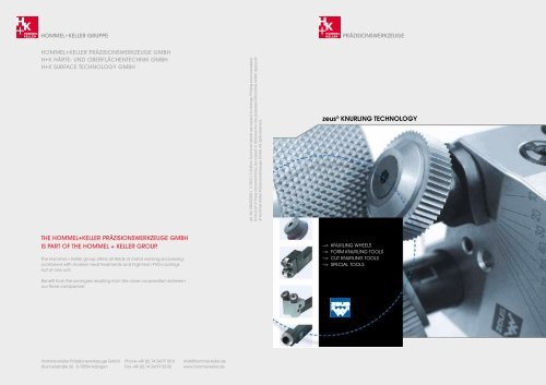
zeus ® KNURLING TECHNOLOGY<br />
THE Hommel+Keller Präzisionswerkzeuge GMBH<br />
is part of the Hommel + Keller group.<br />
The Hommel + Keller group offers all fields of metal working processing,<br />
combined with modern heat treatments and high-tech PVD-coatings<br />
out of one unit.<br />
Benefit from the synergies resulting from the close cooperation between<br />
our three companies!<br />
--> KNURLING WHEELS<br />
--> FORM KNURLING TOOLS<br />
--> CUT KNURLING TOOLS<br />
--> SPECIAL TOOLS<br />
Hommel+Keller Präzisionswerkzeuge GmbH<br />
Brunnenstraße 36 . D-78554 Aldingen<br />
Phone +49 (0) 74 24/97 05-0<br />
Fax +49 (0) 74 24/97 05-50<br />
mail@hommel-keller.de<br />
www.hommel-keller.de
Technology. SerVice. pASSion.<br />
WelcoMe To hoMMel+Keller prÄziSionSWerKzeuge!<br />
High quality standards towards<br />
consumer and industrial goods,<br />
especially in the premium segment,<br />
call for exceptional precision and<br />
surface quality of the knurling<br />
profile. Premium products require<br />
only too often a customized tool<br />
solution. As a result they stand<br />
out with a significant difference<br />
regarding visual and functional<br />
features compared to low-end<br />
products.<br />
Hommel + Keller exceeds all of<br />
these expectations in every aspect<br />
with the premium brand zeus®.<br />
Individual product solutions bring<br />
forth superior final products, as<br />
for example control panels for the<br />
automotive industry or jewellery<br />
for the watch making industry.<br />
Perfect precision, excellent visual<br />
appearance and first-class surface<br />
quality are the performance<br />
parameters for a superior knurling<br />
profile. zeus® knurling tools<br />
offer the decisive advance for your<br />
success.<br />
Our mission is simple:<br />
We will exceed the expectations<br />
of our customers with innovative,<br />
application-oriented tools and<br />
customer-oriented service offerings.<br />
Experience performance by passion:<br />
zeus® <strong>Knurling</strong> Technology.<br />
Welcome!<br />
We work with enthusiasm for your satisfaction:<br />
From innovative products, like the new RF1- LD generation, to the qualified advice and application support.<br />
your SucceSS FAcTorS:<br />
--> appliCation-orienteD<br />
proDuCt range with perFeCt<br />
FunCtionalitY<br />
--> eXCellent Visual proFiles<br />
--> First-Class surFaCe QualitY<br />
--> leaDing <strong>Knurling</strong><br />
teChnologY For high-enD<br />
proDuCts<br />
2 3
TABle oF conTenTS<br />
applications<br />
Our product programme offers tool solutions for manifold requirements of the knurling technique. zeus® knurling tools<br />
are suited to produce standard profiles according to DIN standard, as well as conical, convex, concave and special profiles<br />
(e. g. E, C profiles). The application example below shows the multitude of application possibilities that can be covered with<br />
a zeus® knurling tool.<br />
coNTeNT<br />
--> Company..................................................... Page 02 - 03<br />
--> Applications............................................... Page 05<br />
--> Tool choice................................................. Page 06 - 07<br />
--> Machine types /<br />
Tool characteristics ................................. Page 08 - 09<br />
--> Application techniques........................... Page 10 - 13<br />
--> Form knurling tools................................. Page 14 - 33<br />
--> Cut knurling tools.................................... Page 34 - 43<br />
--> Special tools.............................................. Page 44 - 46<br />
--> Marking tools............................................ Page 47<br />
--> <strong>Knurling</strong> wheels........................................ Page 48 - 57<br />
--> Burnishing Rolls........................................ Page 58<br />
--> Marking Rolls /<br />
Engraving Technology............................. Page 59 - 60<br />
--> Technical appendix.................................. Page 61 - 67<br />
Application example:<br />
Application Profile (DIN 82) Tool <strong>Knurling</strong><br />
Pitch<br />
wheels<br />
Cut knurling RGE30° 291 3 x AA<br />
(Axial) 0,8<br />
Cut knurling RGE45° 241 1 x BL15°<br />
(Axial) 0,6 1 x BR15°<br />
Cut knurling RAA 231 1 x BR30°<br />
(Axial) 1,0<br />
Form knurling RKE 131 1 x KV<br />
(Radial) 0,8<br />
Form knurling RKV 132 1 x KE<br />
(Radial) 0,6<br />
Form knurling RGE45° 141 1 x BL45°<br />
(Radial) 0,8 1 x BR45°<br />
Form knurling RAA 132 1 x AA<br />
(Radial + Axial) 1,0<br />
<strong>Knurling</strong> to a shoulder<br />
Form knurling (Radial) RHV 131 1 x HE<br />
Form knurling (Radial) RE 131 1 x C<br />
Form knurling (Radial) RC 131 1 x E<br />
Form knurling RKAA 311 1 x KAA<br />
(Radial + Axial)<br />
Form knurling (Axial) RAA-plane 311 AA<br />
Marking conical 123 312 40W<br />
Marking revolving zeus® 130 40W<br />
Marking spring-back hommel-keller.de 431 41W<br />
(not visible)<br />
Marking plane XYZ 311 40W<br />
4 5
TOOL CHOICE<br />
The matrix below provides a selection of the tools that are suitable for a specific application. To begin with, please select<br />
the required profile according to DIN 82. Row 2 suggests which technique (Form knurling and / or Cut knurling) is suitable<br />
for producing the required knurling profile. As a next step, please select the machine type. Essential for the choice of tool<br />
is the knurl position on the work piece (at the beginning of / in the middle of or knurling to a shoulder etc.), as outlined by<br />
the different pictograms. By selecting the required application you receive a number of tool suggestions. The product details<br />
for each tool series can be found from page 14 onwards.<br />
Example:<br />
<strong>Knurling</strong> profile<br />
Explanation of arows:<br />
Profile can only be produced in radial tool direction (plunge knurling)<br />
Profile can only be produced in axial tool direction (feed knurling)<br />
Profile can be produced in axial and radial tool direction<br />
Symbols:<br />
LD = Swiss type autolathes<br />
KD = <strong>Automatic</strong> short-turning lathes, Universal lathes, Turning-/milling centre<br />
MS = Multispindle automatic lathes<br />
RT = Rotary indexing machines / Indexing table machines / <strong>Automatic</strong> transfer machines<br />
x = Cut knurling not possible for this application (see also p.13)<br />
▲ = Limited length of knurling profile<br />
* = When cut knurling the manufacture of RBR/RBL profiles is restricted<br />
/<br />
/<br />
<strong>Knurling</strong> profile (DIN 82) <strong>Knurling</strong> technique Machine Profile in the middle Profile starts at work piece Profile starts in the Profile starts in the <strong>Knurling</strong> to a shoulder Profile starts at work Conical knurling profile Face knurling <strong>Knurling</strong> within<br />
type of the work piece, middle of the work middle of the work piece, knurling to a a bore<br />
Form <strong>Knurling</strong> Cut <strong>Knurling</strong> without groove piece, after a groove piece, without a groove shoulder<br />
RAA-Knurl with straight pattern<br />
Work piece<br />
RBL-Knurl, left-hand spiral<br />
Work piece<br />
RBR-Knurl, right-hand spiral<br />
Work piece<br />
RGE-Diamond knurl, left-/right-hand knurl,<br />
points raised (male), 30°<br />
Work piece<br />
RGV-Diamond knurl, left-/right-hand knurl,<br />
points indented (female), 30°<br />
Work piece<br />
RKE-Cross-knurl, points raised (male), 90°<br />
Work piece<br />
RKV-Cross-knurl, points indented (female), 90°<br />
Work piece<br />
Work piece<br />
Work piece<br />
Work piece<br />
Work piece<br />
Work piece<br />
Work piece<br />
Work piece<br />
Work piece<br />
<strong>Knurling</strong> profile RAA<br />
<strong>Knurling</strong> wheel AA<br />
<strong>Knurling</strong> profile RBL<br />
<strong>Knurling</strong> wheel BR<br />
<strong>Knurling</strong> profile RBR<br />
<strong>Knurling</strong> wheel BL<br />
<strong>Knurling</strong> profile RGE<br />
<strong>Knurling</strong> wheel GV<br />
<strong>Knurling</strong> wheel BR<br />
<strong>Knurling</strong> profile RGE<br />
<strong>Knurling</strong> wheel BL<br />
<strong>Knurling</strong> profile RGV<br />
<strong>Knurling</strong> wheel GE<br />
<strong>Knurling</strong> profile RKE<br />
<strong>Knurling</strong> wheel KV<br />
<strong>Knurling</strong> profile RKV<br />
<strong>Knurling</strong> wheel KE<br />
Work piece<br />
<strong>Knurling</strong> wheel BR<br />
swivelled 30°<br />
<strong>Knurling</strong> wheel AA<br />
swivelled 30°<br />
<strong>Knurling</strong> profile RBL<br />
Work piece<br />
Work piece<br />
<strong>Knurling</strong> wheel AA swivelled 30°<br />
Work piece<br />
<strong>Knurling</strong><br />
profile RAA<br />
<strong>Knurling</strong> wheel BL<br />
swivelled 30°<br />
<strong>Knurling</strong><br />
profile RAA<br />
Work<br />
piece<br />
<strong>Knurling</strong> profile RBR<br />
<strong>Knurling</strong> wheel AA<br />
swivelled 30°<br />
<strong>Knurling</strong><br />
profile RGE<br />
<strong>Knurling</strong> wheel AA swivelled 30°<br />
LD 130, 131, 141, 161 130, 131, 141, 161, 162 ▲ , 192 ▲ , 391 130, 131, 141, 161 130, 131, 141, 161 132, 142 132, 142, 162 ▲ , 192 ▲ 311, 312 311, 312 330, 332<br />
KD 130, 131, 141, 161 130, 131, 141, 161, 162 ▲ , 192 ▲ , 391 130, 131, 141, 161 130, 131, 141, 161 132, 142 132, 142, 162 ▲ , 192 ▲ 311, 312 311, 312 330, 332<br />
MS 130, 131, 141, 161 130, 131, 141, 161, 162 ▲ , 192 ▲ , 391 130, 131, 141, 161 130, 131, 141, 161 132, 142 132, 142, 162 ▲ , 192 ▲ 311, 312 311, 312 330, 332<br />
RT 192 ▲ , 391 162 ▲ , 192 ▲ 330, 332<br />
LD 231 231<br />
KD x<br />
231 231<br />
MS 231 231<br />
RT<br />
x<br />
x x x x x<br />
LD 130, 131, 141, 161 130, 131 130, 131, 141, 161 130, 131, 141, 161 132, 142 132, 142, 162 ▲ , 192 ▲ 311, 312 311, 312 330, 332<br />
KD 130, 131, 141, 161 130, 131 130, 131, 141, 161 130, 131, 141, 161 132, 142 132, 142, 162 ▲ , 192 ▲ 311, 312 311, 312 330, 332<br />
MS 130, 131, 141, 161 130, 131 130, 131, 141, 161 130, 131, 141, 161 132, 142 132, 142, 162 ▲ , 192 ▲ 311, 312 311, 312 330, 332<br />
RT 130, 131 162 ▲ , 192 ▲<br />
LD 231* 231*<br />
KD x<br />
231* 231*<br />
MS 231* 231*<br />
RT<br />
x<br />
x x x x x<br />
LD 130, 131, 141, 161 130, 131 130, 131, 141, 161 130, 131, 141, 161 132, 142 132, 142, 162 ▲ , 192 ▲ 311, 312 311, 312 330, 332<br />
KD 130, 131, 141, 161 130, 131 130, 131, 141, 161 130, 131, 141, 161 132, 142 132, 142, 162 ▲ , 192 ▲ 311, 312 311, 312 330, 332<br />
MS 130, 131, 141, 161 130, 131 130, 131, 141, 161 130, 131, 141, 161 132, 142 132, 142, 162 ▲ , 192 ▲ 311, 312 311, 312 330, 332<br />
RT 130, 131 162 ▲ , 192 ▲<br />
LD 231* 231*<br />
KD<br />
x<br />
231* 231*<br />
MS 231* 231*<br />
x<br />
x x x x<br />
x<br />
RT<br />
LD 130, 131, 132, 161 132 132 311, 312 311, 312 330, 332<br />
KD 130, 131, 132, 161 Only suitable<br />
132 132 311, 312 311, 312 330, 332<br />
MS 130, 131, 132, 161 for plunge knurling 132 132 311, 312 311, 312 330, 332<br />
RT<br />
162 ▲<br />
LD 141, 161 141, 161, 162, 192 ▲ 141, 161 141, 161 142 141, 162 ▲ , 192 ▲ 340, 342<br />
KD 141, 161 141, 161, 162, 192 ▲ 141, 161 141, 161 142 141, 162 ▲ , 192 ▲ 340, 342<br />
MS 141, 161 141, 161, 162, 192 ▲ 141, 161 141, 161 142 141, 162 ▲ , 192 ▲ 340, 342<br />
RT 161, 162 ▲ , 192 ▲ 162 ▲ , 192 ▲<br />
LD 241, 291 ▲ 241<br />
KD 241 , 291<br />
x<br />
241<br />
MS 241 , 291 ▲ 241<br />
x<br />
x x x x<br />
x<br />
RT<br />
291 ▲<br />
LD 130, 131 132 311, 312 311, 312 330, 332<br />
RGV:<br />
RGV:<br />
RGV:<br />
RGV:<br />
KD 130, 131 132 311, 312 311, 312 330, 332<br />
Only suitable<br />
Only suitable<br />
Only suitable<br />
Only suitable<br />
MS 130, 131<br />
for plunge knurling<br />
for plunge knurling<br />
for plunge knurling<br />
132<br />
for plunge knurling<br />
311, 312 311, 312 330, 332<br />
RT 311, 312 330, 332<br />
LD 130, 131 132 330, 332<br />
RKE:<br />
RKE:<br />
RKE:<br />
RKE:<br />
KD 130, 131 132 330, 332<br />
Only suitable<br />
Only suitable<br />
Only suitable<br />
Only suitable<br />
MS 130, 131<br />
for plunge knurling<br />
for plunge knurling<br />
for plunge knurling<br />
132<br />
for plunge knurling<br />
330, 332<br />
RT 330, 332<br />
LD 130, 131 132 330, 332<br />
RKV:<br />
RKV:<br />
RKV:<br />
RKV:<br />
KD 130, 131<br />
Only suitable<br />
Only suitable<br />
Only suitable<br />
132<br />
Only suitable<br />
330, 332<br />
MS 130, 131<br />
for plunge knurling<br />
for plunge knurling<br />
for plunge knurling<br />
132<br />
for plunge knurling<br />
330, 332<br />
RT 330, 332<br />
6 7
Machine types<br />
Tool Characteristics<br />
Machine types<br />
Distinctive features according to machine characteristics<br />
Tool Characteristics<br />
Distinctive features according to machine types and machine characteristics<br />
Swiss type autolathes<br />
<strong>Automatic</strong> short-turning lathes /<br />
Universal lathes /<br />
Turning-/milling centre<br />
Tool fitting in:<br />
• Long slide<br />
• Cross slide<br />
• Turret<br />
Tool fitting in:<br />
• Long slide<br />
• Cross slide<br />
• Turret<br />
CNC<br />
Conventional<br />
CNC<br />
Conventional<br />
Right-hand turning<br />
Left-hand turning<br />
Direction of rotation<br />
universal<br />
Right-hand turning<br />
Left-hand turning<br />
Direction of rotation<br />
universal<br />
LD<br />
KD<br />
<strong>Knurling</strong> tools for<br />
CNC lathes/autolathes<br />
On the knurling tools for CNC lathes /<br />
autolathes, the centre height is already<br />
incorporated (centre height = top of<br />
shank). As a result it is possible to employ<br />
these in CNC lathes / autolathes without<br />
adjustment of the centre height (fixed<br />
tool holder). Basically these knurling tool<br />
series are also suitable for conventional<br />
lathes / autolathes, insofar as the centre<br />
height can be set on the machine.<br />
Tool holder fixed (not adjustable<br />
in height) centre height is<br />
incorporated in the tool.<br />
R = right<br />
L = left<br />
The zeus® range of products includes special<br />
designs for right- (R) and left-oriented (L) lathes/<br />
autolathes. Insofar as constructionally possible, zeus®<br />
<strong>Knurling</strong> tools are of modular tool design (M). These<br />
(M)-versions can be used rotating both right and left.<br />
LD<br />
KD<br />
MS<br />
Multispindle automatic lathes<br />
Rotary indexing machine /<br />
Indexing table type machine /<br />
Transfer machine<br />
Tool fitting in:<br />
• Long slide<br />
• Cross slide<br />
• Support of an<br />
automatic lathe<br />
Tool fitting in:<br />
• Spindle nose unit<br />
CNC<br />
Conventional<br />
Right-hand turning<br />
Left-hand turning<br />
Direction of rotation<br />
universal<br />
Tool rotating<br />
Work piece fix<br />
Direction of rotation<br />
universal<br />
MS<br />
RT<br />
<strong>Knurling</strong> tools for<br />
conventional lathes/autolathes<br />
zeus® <strong>Knurling</strong> tools for conventional<br />
lathes / autolathes are designed in a<br />
way that the centre height adjustment is<br />
effected by means of the tool holder. As<br />
a result these tools have a basic design.<br />
<strong>Knurling</strong> tools for<br />
swiss type autolathes<br />
On knurling tools that are suitable for swiss<br />
type autolathes, the knurling wheel must<br />
not protrude over the front edge of the<br />
shank, in order to prevent a collision<br />
with the guide bush. Most knurling<br />
tools with a shank height of 8-16 mm<br />
are suitable for swiss type autolathes.<br />
Basically these can also be used in CNC<br />
and conventional lathes / autolathes.<br />
Tool holder adjustable.<br />
Centre height has to be set.<br />
guide<br />
bushing<br />
View X<br />
View X<br />
knurling wheel is<br />
not fixed above<br />
shank front edge<br />
centre height<br />
is integrated<br />
R = right<br />
R = right<br />
L = left<br />
zeus® <strong>Knurling</strong> wheels for conventional machine<br />
types can be used rotating both right and left.<br />
L = left<br />
On swiss type autolathes the knurling wheel<br />
should be positioned as closely as possible to the<br />
clamping of the work piece, to be able to machine<br />
small work piece diameters. For this reason, on the<br />
knurling tools of the zeus® RD1 and RD2 series<br />
with the shank dimensions of 8 x 8 to 16 x 16,<br />
the knurling wheels are not arranged centrally but<br />
laterally offset.<br />
LD<br />
KD<br />
MS<br />
LD<br />
<strong>Knurling</strong> tools for axial machining<br />
<strong>Knurling</strong> tools for axial machining of the<br />
work piece can be clamped axially to the<br />
work piece on all conventional and CNC<br />
lathes/autolathes with tailstock. The<br />
machining takes place through a work<br />
piece rotating in a tool fixed and stationary<br />
in a tailstock.<br />
On rotary indexing machines / indexing<br />
table machines / automatic transfer<br />
machines a stationary work piece is<br />
machined by a tool rotating axially.<br />
Machining options:<br />
• Tool stationary<br />
• Work piece revolving<br />
• Direction of rotation universal<br />
• Tool revolving<br />
• Work piece stationary<br />
• Direction of rotation universal<br />
LD<br />
KD<br />
MS<br />
RT<br />
8 9
KNURLING TECHNIQUES<br />
In knurling technology two different application techniques can be distinguished: Cut <strong>Knurling</strong> and Form <strong>Knurling</strong>. Both<br />
techniques have their own characteristics, range of applications, advantages and limitations. Whereas one advantage of<br />
form knurling is the easy tool handling, cut knurling is always the preferred method whenever the surface quality requires<br />
uncompromising precision. On the following pages, the different attributes, the range of applications, their advantages and<br />
limitations are summarized.<br />
A fundamental distinction lies in the relation between tool direction and possible knurling profiles. The chart below outlines<br />
this important distinction:<br />
Application Techniques<br />
KNURLING TECHNIQUES<br />
Form <strong>Knurling</strong><br />
Without swarf<br />
removal<br />
Cut <strong>Knurling</strong><br />
Swarf<br />
removal<br />
Plunge <strong>Knurling</strong><br />
Radial<br />
tool direction<br />
Feed <strong>Knurling</strong><br />
Axial<br />
tool direction<br />
Plunge and Feed <strong>Knurling</strong><br />
Radial and axial<br />
tool direction<br />
Feed <strong>Knurling</strong><br />
Axial<br />
tool direction<br />
POSSIBLE KNURLING PROFILES<br />
content<br />
RAA<br />
RAA<br />
RAA<br />
RAA<br />
<strong>Knurling</strong> techniques<br />
Application characteristics<br />
Form <strong>Knurling</strong><br />
Application characteristics<br />
Cut <strong>Knurling</strong><br />
RBR<br />
RBL<br />
RBR<br />
RBL<br />
RBR<br />
RGE RGV<br />
RGE* RGE*<br />
RBL<br />
RBR<br />
RGE<br />
RBL<br />
RKE<br />
RKV<br />
* Only suitable with knurling tools RD2/RD3/RF2/RF3<br />
10 11
Application characteristics – Form <strong>Knurling</strong><br />
Application characteristics – CUT <strong>Knurling</strong><br />
Form knurling is a non-cutting process during which a surface compression of the work piece takes place. As form knurling<br />
is a cold forming process, the technique is only suitable for cold deformable materials. As a result of the forming process,<br />
the outer diameter is increased. A main advantage of the technique lies in the application diversity. With form knurling all<br />
knurling profiles can be produced and it is also suitable for front, internal or conical knurling. It is further possible to knurl<br />
up to a shoulder.<br />
Cut knurling is the milling alternative to form knurling. During feed, material is removed. This technique is especially<br />
suitable for thin-walled work pieces, soft materials (e.g. plastics) or difficult to machine materials. Cut knurling excels in<br />
high precision and excellent surface quality, a reason why it is recommended for producing high-quality visual profiles.<br />
Contrary to form knurling, the surface compression and the material displacement are negligible. The strain on the machine<br />
is also relatively small. One major restriction of the cut knurling technique is the smaller range of application. Cut knurling<br />
is only suitable for producing the knurling profiles RAA and RGE. Furthermore, due to the minimal surface compression, the<br />
toughness of the knurling profile is reduced.<br />
Form <strong>Knurling</strong><br />
Cut <strong>Knurling</strong><br />
Application<br />
Processing of cold deformable material<br />
Suitable for all knurling patterns, profiles and markings<br />
Suitable for front and internal knurling<br />
<strong>Knurling</strong> to a shoulder<br />
Tool can be started at any position of the work piece<br />
Application<br />
Suitable for most materials<br />
Suitable for thin-walled work pieces<br />
Suitable for very small work pieces<br />
High precision and surface quality, therefore suitable for excellent visual profiles<br />
Limited range of application: The knurling profiles RAA and RGE can be produced<br />
with all tool series. The possibility of the knurling profiles RBR and RBL is limited<br />
Only suitable for cylindrical work pieces in axial tool direction<br />
<strong>Knurling</strong> to be started at work piece end or in the middle after a groove<br />
<strong>Knurling</strong> up to a shoulder is not possible<br />
<strong>Knurling</strong> profile<br />
on work piece<br />
DIN 82:<br />
<strong>Knurling</strong> profile<br />
on work piece<br />
DIN 82:<br />
RAA RBL RBR RGE RGV RKE RKV RAA RBL* RBR* RGE<br />
Characteristics<br />
Handling<br />
Characteristics<br />
Handling<br />
Work piece diameter is increased through<br />
displacement<br />
Surface is compressed<br />
More strain on machine compared to cut<br />
knurling<br />
Form knurling of thin-walled work pieces<br />
can cause difficulties<br />
<strong>Knurling</strong> of small diameters can cause<br />
difficulties<br />
Preparation of work piece generally not required<br />
(reduced setting time)<br />
Easy tool handling<br />
No major change in diameter after knurling<br />
Minimal surface compression<br />
Less strain on machine compared to form<br />
knurling<br />
Minimal strain on tool and work piece<br />
Precise setting of tool and fine<br />
adjustment required<br />
Precise setting of work piece required<br />
* With cut knurling, the manufacture of the knurling profiles RBR and RBL is subject to restriction.<br />
12 13
zeus ® ForM <strong>Knurling</strong> ToolS rD1<br />
ForM <strong>Knurling</strong> ToolS<br />
cuT <strong>Knurling</strong> ToolS<br />
SpeciAl ToolS<br />
The zeus® RD1 series for form knurling applications is the economic and easy solution for producing all kinds of<br />
knurling profiles. A classic, that can also be used for the marking of work pieces on autolathes. A further advantage:<br />
The knurling profile can start at any position of the work piece – a groove is not required.<br />
APPlIcATIoN ADVANTAGes:<br />
eAsy Tool HANDlING:<br />
Easy application and tool handling<br />
Minimal work piece preparation<br />
Integrated set screws for easy<br />
adjustment of the clearance angle<br />
Click-pin® versions for still faster<br />
and safer change of knurling wheels<br />
HIGH weAR ResIsTANce:<br />
Special surface hardening for<br />
increased tool life<br />
Carbide pins for higher speed<br />
rates, faster production,<br />
prolonged life<br />
moDUlAR PRoDUcT DesIGN:<br />
Modular shank system for costeffective<br />
use on all CNC- / and<br />
cam- controlled swiss type autolathes<br />
moDUlAR PRoDUcT DesIGN<br />
For swiss type autolathe versions:<br />
clIcK-PIN®-sysTem<br />
For fast and safe change of the knurling wheel:<br />
--> No more break off through overtightening<br />
--> No more loosening through impact, hits or vibration<br />
--> Quick change and positioning of the knurling wheel<br />
KNURlING To sHoUlDeR<br />
Tool types for knurling to shoulder:<br />
content<br />
ForM <strong>Knurling</strong> ToolS:<br />
RD1, RD2, RD3<br />
cuT <strong>Knurling</strong> ToolS:<br />
RF1, RF2, RF3<br />
SpeciAl ToolS<br />
APPlIcATIoN exAmPle:<br />
Bushing<br />
APPLICATION:<br />
Material:<br />
Cu2n38Pb2<br />
<strong>Knurling</strong> Profile/Pitch<br />
(DIN 82): RGE45° / P. 0.6<br />
Machine: Traub TD 60<br />
No. of pcs. produced/<br />
knurling wheel: 150,000<br />
APPLICATION PARAMETERS zeus® RD1:<br />
<strong>Knurling</strong> tool: 130-12U250606<br />
<strong>Knurling</strong> wheel: GV45°20x6x6, P. 0.6<br />
Cycle time:<br />
0.8 sec/piece<br />
Speed rate:<br />
240 m/min<br />
Feed rate:<br />
0.2 mm/rev<br />
Tool life knurling wheel: 2,000 (min/knurling wheel)<br />
Performance:<br />
18.378 m²/knurling wheel<br />
14 15
zeus® Form <strong>Knurling</strong> Tools RD1<br />
zeus® Form <strong>Knurling</strong> Tools RD1<br />
zeus ® Form <strong>Knurling</strong> Tool 130:<br />
THE CLASSIC WITH ONE KNURLING WHEEL –<br />
CONVINCING EFFICIENCY FOR CONVENTIONAL AUTOLATHES!<br />
zeus ® Form <strong>Knurling</strong> Tool 131:<br />
THE CLASSIC WITH ONE KNURLING WHEEL –<br />
CONVINCING EFFICIENCY FOR SWISS TYPE AUTOLATHES!<br />
ORDER EXAMPLE:<br />
Tool holder No. 130-16 U 250806-A<br />
Product series<br />
Shank size 16 x 16 mm<br />
Right-/ and left- hand use<br />
Model A<br />
For knurling wheels<br />
25 x 8 x 6 (Ø x width x bore)<br />
Machine type: Conventional and CNC – suitable for:<br />
• Lathe / autolathes<br />
• Swiss type autolathes<br />
• <strong>Automatic</strong> short-turning lathes<br />
• Multispindle automatic lathes<br />
Application: Form knurling (non-cutting forming)<br />
<strong>Knurling</strong> profile<br />
on work piece<br />
DIN 82: RAA RBL RBR RGE RGV RKE RKV<br />
<strong>Knurling</strong><br />
wheels: AA BR BL GV GE KV KE<br />
Tool<br />
direction:<br />
Product<br />
highlights:<br />
• Plunge knurling: Suitable for all knurling profiles,<br />
patterns and markings<br />
• Feed knurling: Suitable for RAA, RBL, RBR<br />
• Centre height adjustable<br />
• Integrated set screws for easy adjustment of the<br />
clearance angle<br />
• Carbide pins<br />
• Special surface hardening for increased wear resistance<br />
TOOL TYPES:<br />
Tool holder Working area a b c d e f x <strong>Knurling</strong> Spare part<br />
No. Ø mm mm mm mm mm mm mm mm wheels mm Pin<br />
width Ø 15 width Ø 15 width Ø 15 (Ø x width x bore)<br />
width Ø 25 width Ø 25 width Ø 25<br />
130-08U150404-A 3-20 8 8 99 10 19 10 4 10 / 15 x 4 x 4 06TER0972<br />
130-08U150604-A 3-20 8 8 99 14 19 10 4 10 / 15 x 6 x 4 06TER0974<br />
130-10U150404-A 3-20 10 10 99 10 - 10 4 10 / 15 x 4 x 4 06TER0972<br />
130-10U150604-A 3-20 10 10 99 14 19 10 4 10 / 15 x 6 x 4 06TER0974<br />
130-10U250806-A 15-200 10 10 110,5 16 30,5 16 5,5 20 / 25 x 8 x 6 06TER0980<br />
130-12U150404-A 3-20 12 12 99 12 - 12 4 10 / 15 x 4 x 4 06TER0973<br />
130-12U250606-A 15-200 12 12 110,5 14 30,5 14 5,5 20 / 25 x 6 x 6 06TER0979<br />
130-12U250806-A 15-200 12 12 110,5 16 30,5 16 5,5 20 / 25 x 8 x 6 06TER0980<br />
130-14U150604-A 3-20 14 14 99 14 - 14 4 10 / 15 x 6 x 4 06TER0974<br />
130-14U250606-A 15-200 14 14 110,5 14 - 14 5,5 20 / 25 x 6 x 6 06TER0979<br />
130-16U250806-A 15-200 16 16 110,5 16 - 16 5,5 20 / 25 x 8 x 6 06TER0980<br />
130-20U251006-A 15-200 20 20 110,5 20 - 20 5,5 20 / 25 x 10 x 6 06TER0982<br />
130-20U251506-A 15-200 20 25 110,5 25 - 20 5,5 20 / 25 x 15 x 6 06TER0983<br />
Tool holder Working area a b c d e f x <strong>Knurling</strong> Spare part<br />
No. Ø mm inch inch/ mm mm mm mm mm wheels inch Pin<br />
mm<br />
(Ø x width x bore)<br />
130-70U515318-A 3-20 5⁄16 5⁄16 96 10 16 10 1 5/16 x 5/32 x 1/8 06TER0985<br />
130-75U123131-A 3-20 1⁄2 1⁄2 96,3 12,7 - 12,7 1,3 1/2 x 3/16 x 3/16 06TER0986<br />
130-80U581414-A 3-20 5⁄8 5⁄8 107 15,8 - 15,8 2 5/8 x 1/4 x 1/4 06TER0988<br />
130-85U343814-A 15-200 3⁄4 3⁄4 108 19,05 - 19,05 3 3/4 x 3/8 x 1/4 06TER0970<br />
130-90U343814-A 15-200 3⁄4 20 mm 111 20 - 25,4 6 3/4 x 3/8 x 1/4 06TER0970<br />
Carbide pin<br />
Carbide pin<br />
ORDER EXAMPLE:<br />
Tool holder No.<br />
Product series<br />
Shank size 10 x 10 mm<br />
Left-hand use<br />
TOOL TYPES:<br />
f<br />
d<br />
131 -10 L 100306 - A (-Z)<br />
with ClickPin®<br />
Model A<br />
For knurling wheels<br />
10 x 3 x 6 (Ø x width x bore)<br />
Machine type: Conventional and CNC – suitable for:<br />
• Swiss type autolathes<br />
Application:<br />
Form knurling (non-cutting forming)<br />
<strong>Knurling</strong> profile<br />
on work piece<br />
DIN 82: RAA RBL RBR RGE RGV RKE RKV<br />
<strong>Knurling</strong><br />
<strong>Knurling</strong> wheel: AA BR BL GV GE KV KE<br />
Tool<br />
direction:<br />
Product<br />
highlights:<br />
• Plunge knurling: Suitable for all knurling profiles,<br />
patterns and markings<br />
• Feed knurling: Suitable for RAA, RBL, RBR<br />
• Modular shank construction for conversion to alternative<br />
shank sizes<br />
• Integrated set screws for easy adjustment of the clearance angle<br />
• Carbide pins<br />
• Special surface hardening for increased wear resistance<br />
Tool holder Working area a b c* d e* f* x* <strong>Knurling</strong> wheels Spare part<br />
No. Ø mm mm mm mm mm mm mm mm mm (Ø x width x bore) Pin<br />
131-08L150404-A 3-50 8 8 99 12 19 15,5 4 10/15 x 4 x 4 06TER0960<br />
131-08R150404-A 3-50 8 8 99 12 19 15,5 4 10/15 x 4 x 4 06TER0960<br />
131-10L150404-A 3-50 10 10 99 12 19 17,5 4 10/15 x 4 x 4 06TER0960<br />
131-10R150404-A 3-50 10 10 99 12 19 17,5 4 10/15 x 4 x 4 06TER0960<br />
131-12L150404-A 3-50 12 12 99 12 19 19,5 4 10/15 x 4 x 4 06TER0960<br />
131-12R150404-A 3-50 12 12 99 12 19 19,5 4 10/15 x 4 x 4 06TER0960<br />
131-16L150404-A 3-50 16 16 99 12 19 23,5 4 10/15 x 4 x 4 06TER0960<br />
131-16R150404-A 3-50 16 16 99 12 19 23,5 4 10/15 x 4 x 4 06TER0960<br />
Mit ClickPin®:<br />
131-08L150404-A-Z 3-50 8 8 99 12 19 15,5 4 10/15 x 4 x 4 06TER1015<br />
131-08R150404-A-Z 3-50 8 8 99 12 19 15,5 4 10/15 x 4 x 4 06TER1015<br />
131-10L150404-A-Z 3-50 10 10 99 12 19 17,5 4 10/15 x 4 x 4 06TER1015<br />
131-10R150404-A-Z 3-50 10 10 99 12 19 17,5 4 10/15 x 4 x 4 06TER1015<br />
131-12L150404-A-Z 3-50 12 12 99 12 19 19,5 4 10/15 x 4 x 4 06TER1015<br />
131-12R150404-A-Z 3-50 12 12 99 12 19 19,5 4 10/15 x 4 x 4 06TER1015<br />
131-16L150404-A-Z 3-50 16 16 99 12 19 23,5 4 10/15 x 4 x 4 06TER1015<br />
131-16R150404-A-Z 3-50 16 16 99 12 19 23,5 4 10/15 x 4 x 4 06TER1015<br />
c<br />
* width Ø15<br />
x<br />
e<br />
Right<br />
c<br />
a<br />
b<br />
d f<br />
2<br />
x<br />
e<br />
Left<br />
b a<br />
06TER0960<br />
06TER1015<br />
f<br />
2<br />
d<br />
x<br />
e<br />
c<br />
a<br />
b<br />
x<br />
c<br />
a<br />
b<br />
CLICK-PIN®-SYSTEM:<br />
For fast and safe change of the<br />
knurling wheel:<br />
--> No more break off through overtightening<br />
--> No more loosening through impact, hits<br />
or vibration<br />
--> Quick change and positioning of the<br />
knurling wheel<br />
SHANK ADAPTORS:<br />
Shank size Part-No.<br />
10 x 10 21BHR0833<br />
12 x 12 21BHR0834<br />
16 x 16 21BHR0835<br />
Modular shank construction for conversion to alternative shank sizes<br />
16 17
f<br />
b a<br />
zeus® Form <strong>Knurling</strong> Tools RD1<br />
zeus® Form <strong>Knurling</strong> Tools RD1<br />
zeus ® FORM KNURLING TOOL 131:<br />
THE CLASSIC WITH ONE KNURLING WHEEL –<br />
CONVINCING EFFICIENCY FOR CNC-AUTOLATHES!<br />
zeus ® FORM KNURLING TOOL 132:<br />
THE CLASSIC FOR KNURLING TO A SHOULDER –<br />
CONVINCING FUNCTIONALITY!<br />
ORDER EXAMPLE:<br />
Tool holder No.<br />
Product series<br />
Shank size 20 x 20 mm<br />
Right-/ and left- hand use<br />
TOOL TYPES:<br />
131 -20 U 250806- A (-Z)<br />
with ClickPin®<br />
Model A<br />
For knurling wheels<br />
25 x 8 x 6 (Ø x width x bore)<br />
Machine type: Conventional and CNC – suitable for:<br />
• <strong>Automatic</strong> short-turning lathes, Universal lathes,<br />
Turning- / milling centre<br />
• Multispindle automatic lathes<br />
Application:<br />
Form knurling (non-cutting forming)<br />
<strong>Knurling</strong> profile<br />
on work piece<br />
DIN 82: RAA RBL RBR RGE RGV RKE RKV<br />
<strong>Knurling</strong><br />
wheels: AA BR BL GV GE KV KE<br />
Tool<br />
direction:<br />
Product<br />
highlights:<br />
• Plunge knurling: Suitable for all knurling profiles,<br />
patterns and markings<br />
• Feed knurling: Suitable for RAA, RBL, RBR<br />
• Integrated set screws for easy adjustment of the clearance angle<br />
• Carbide pins<br />
• Special surface hardening for increased wear resistance<br />
Tool holder Working area a b c mm e mm f mm x mm <strong>Knurling</strong> wheels Spare part<br />
No. Ø mm mm mm width Ø 25 width Ø 25 width Ø 25 width Ø 25 mm (Ø x width x bore) Pin<br />
131-20U250806-A 8-200 20 20 109,5 29,5 32,5 5,5 20 / 25 x 8 x 6 06TER0965<br />
131-25U250806-A 8-200 25 20 109,5 29,5 37,5 5,5 20 / 25 x 8 x 6 06TER0965<br />
With ClickPin®:<br />
131-20U250806-A-Z 8-200 20 20 109,5 29,5 32,5 5,5 20 / 25 x 8 x 6 06TER1018<br />
131-25U250806-A-Z 8-200 25 20 109,5 29,5 37,5 5,5 20 / 25 x 8 x 6 06TER1018<br />
Tool holder Working area a b c e f x <strong>Knurling</strong> wheels Spare part<br />
No. Ø mm inch mm mm mm mm mm mm (Ø x width x bore) Pin<br />
131-85U343814-A 8-200 3/4" 20 116,5 24,5 29 2,5 3/4" x 3/8" x 1/4" 06TER0989<br />
131-90U343814-A 8-200 1" 20 116,5 24,5 35 2,5 3/4" x 3/8" x 1/4" 06TER0989<br />
06TER0965/<br />
06TER0989<br />
06TER1018<br />
ORDER EXAMPLE:<br />
Tool holder No.<br />
Product series<br />
Shank size 8 x 8 mm<br />
Left-hand use<br />
TOOL TYPES:<br />
132-08 L 150611- A<br />
Model A<br />
For knurling wheels<br />
15 x 6 x 6/11 (Ø x width x bore)<br />
Machine type: Conventional and CNC – suitable for:<br />
• Swiss type autolathes<br />
Application:<br />
Form knurling (non-cutting forming)<br />
<strong>Knurling</strong> profile<br />
on work piece<br />
DIN 82: RAA RBL RBR RGE RGV RKE RKV<br />
<strong>Knurling</strong><br />
wheels: AA BR BL GV GE KV KE<br />
Tool<br />
direction:<br />
Product<br />
highlights:<br />
• Plunge knurling: Suitable for all knurling profiles,<br />
patterns and markings<br />
• Feed knurling: Suitable for RAA, RBL, RBR<br />
• <strong>Knurling</strong> to a shoulder – knurling wheel fixed by a shoulder<br />
pin. Fitting of the knurling wheel on the pin adjustable.<br />
• Modular shank construction for conversion to alternative<br />
shank sizes<br />
• Integrated set screws for easy adjustment of the<br />
clearance angle<br />
• Special surface hardening for increased wear resistance<br />
Tool holder Working area a b c d e f <strong>Knurling</strong> wheels Spare part Spare part<br />
No. Ø mm mm mm mm mm mm mm mm (Ø x width x bore) Shoulder pin Run disc<br />
132-08L150611-A 3-50 8 8 101 19 21 16 15 x 6 x 6/11 06TER0444 21BHR0375<br />
132-08R150611-A 3-50 8 8 101 19 21 16 15 x 6 x 6/11 06TER0444 21BHR0375<br />
132-10L150611-A 3-50 10 10 101 19 21 18 15 x 6 x 6/11 06TER0444 21BHR0375<br />
132-10R150611-A 3-50 10 10 101 19 21 18 15 x 6 x 6/11 06TER0444 21BHR0375<br />
132-12L150611-A 3-50 12 12 101 19 21 20 15 x 6 x 6/11 06TER0444 21BHR0375<br />
132-12R150611-A 3-50 12 12 101 19 21 20 15 x 6 x 6/11 06TER0444 21BHR0375<br />
132-16L150611-A 3-50 16 16 101 19 21 24 15 x 6 x 6/11 06TER0444 21BHR0375<br />
132-16R150611-A 3-50 16 16 101 19 21 24 15 x 6 x 6/11 06TER0444 21BHR0375<br />
06TER0444<br />
21BHR0375<br />
e<br />
c<br />
f<br />
e<br />
c<br />
f<br />
e<br />
e<br />
c<br />
c<br />
b<br />
d<br />
b<br />
d<br />
d<br />
b<br />
f<br />
a<br />
a<br />
Right<br />
Left<br />
a<br />
X<br />
CLICK-PIN®-SYSTEM:<br />
For fast and safe change of the knurling wheel:<br />
--> No more break off through overtightening<br />
--> No more loosening through impact, hits or vibration<br />
--> Quick change and positioning of the knurling wheel<br />
KNURLING TO A SHOULDER:<br />
Suitable for knurling up to<br />
a shoulder<br />
SHANK ADAPTORS:<br />
Shank size Part-No.<br />
10 x 10 21BHR0833<br />
12 x 12 21BHR0834<br />
16 x 16 21BHR0835<br />
Modular shank construction for conversion to alternative shank sizes<br />
18 19
zeus® Form <strong>Knurling</strong> Tools RD1<br />
zeus ® ForM <strong>Knurling</strong> ToolS rD2-MoDel 141/142<br />
zeus ® FORM KNURLING TOOL 132:<br />
The clASSic For <strong>Knurling</strong> To A ShoulDer –<br />
conVincing FuncTionAliTy!<br />
ORDER EXAMPLE:<br />
Tool holder No.<br />
Product series<br />
Shank size 20 x 20 mm<br />
Right-/ and left- hand use<br />
TOOL TYPES:<br />
132-20 U 200813- A<br />
Model A<br />
For knurling wheels<br />
20 x 8 x 6/13 (Ø x width x bore)<br />
Machine type: Conventional and CNC – suitable for:<br />
• <strong>Automatic</strong> short-turning lathes, Universal lathes,<br />
Turning- / milling centre<br />
• Multispindle automatic lathes<br />
Application:<br />
Form knurling (non-cutting forming)<br />
<strong>Knurling</strong> profile<br />
on work piece<br />
DIN 82: RAA RBL RBR RGE RGV RKE RKV<br />
<strong>Knurling</strong><br />
wheels: AA BR BL GV GE KV KE<br />
Tool<br />
direction:<br />
Product<br />
highlights:<br />
• Plunge knurling: Suitable for all knurling profiles,<br />
patterns and markings<br />
• Feed knurling: Suitable for RAA, RBL, RBR<br />
• <strong>Knurling</strong> to a shoulder – knurling wheel fixed by a shoulder<br />
Fitting of the knurling wheel on the pin adjustable<br />
• Integrated set screws for easy adjustment of the clearance angle<br />
• Special surface hardening for increased wear resistance<br />
Tool holder Working area a b c d e f <strong>Knurling</strong> wheels Spare part Spare part<br />
No. Ø mm mm mm mm mm mm mm mm (Ø x width x bore) Shoulder pin Run disc<br />
132-20U200813-A 8-200 20 20 105,5 24 25,5 30 20 x 8 x 6/13 06TER0445 21BHR0380<br />
132-25U200813-A 8-200 25 20 105,5 24 25,5 35 20 x 8 x 6/13 06TER0445 21BHR0380<br />
06TER0445<br />
The zeus® RD2 series is the first choice for producing RGE profiles in axial tool direction. Working axially, the knurl<br />
width can be chosen according to any size required. The tool series offers many add-ons, that simplify the tool<br />
handling. Due to its modular design, the RD2 is suitable for both right-hand and left-hand operations. For the swiss<br />
type autolathe versions the flexible shank system allows a conversion to different shank sizes.<br />
APPlIcATIoN ADVANTAGes:<br />
eAsy Tool HANDlING:<br />
Easy appliance and tool handling<br />
Minimal work piece preparation<br />
Integrated set screws for easy<br />
adjustment of the clearance angle<br />
Pin with face – fixed by a screw – for a<br />
quick replacement of the knurling wheel<br />
Click-pin® versions for still faster and safer<br />
change of knurling wheels<br />
HIGH weAR ResIsTANce:<br />
Special surface hardening for<br />
increased tool life<br />
Carbide pins for higher speed<br />
rates, faster production,<br />
prolonged life<br />
moDUlAR PRoDUcT DesIGN:<br />
Modular shank system for costeffective<br />
use on all CNC- / and<br />
cam- controlled swiss type auto<br />
lathes<br />
Modular system: universal knurling<br />
tool for both right- / and left-hand<br />
orientation. Retooling through fast<br />
and easy turning of the knurling<br />
head<br />
Tool holder Working area a b c d e f <strong>Knurling</strong> wheels Spare part Spare part<br />
No. Ø mm inch mm mm mm mm mm mm (Ø x width x bore) Shoulder pin Run disc<br />
132-85U200813-A 8-200 3/4" 20 105,5 24 25,5 29 20 x 8 x 6/13 06TER0445 21BHR0380<br />
132-90U200813-A 8-200 1" 20 105,5 24 25,5 35,4 20 x 8 x 6/13 06TER0445 21BHR0380<br />
e<br />
c<br />
e<br />
c<br />
21BHR0380<br />
moDUlAR PRoDUcT DesIGN CLICK-PIN®-SYSTEM KNURLING TO SHOULDER<br />
For swiss type autolathe versions:<br />
For fast and safe change of the knurling wheel:<br />
--> No more break off through overtightening<br />
--> No more loosening through impact, hits or vibration<br />
--> Quick change and positioning of the knurling wheel<br />
Tool types for knurling to<br />
shoulder:<br />
f<br />
f<br />
d<br />
Right<br />
a<br />
b<br />
f<br />
d<br />
d<br />
Left<br />
b b a a<br />
1<br />
KNURLING TO A SHOULDER:<br />
Suitable for knurling up to<br />
a shoulder<br />
APPLICATION EXAMPLE:<br />
Threaded bushing M5<br />
APPLICATION:<br />
Material:<br />
C35Pb<br />
<strong>Knurling</strong> Profile/Pitch<br />
(DIN 82): RGE30° / P. 0.8<br />
Machine:<br />
Tornos SAS 16DC<br />
No. of pcs. produced/<br />
knurling wheel: 120,000<br />
APPLICATION PARAMETERS zeus® RD2:<br />
<strong>Knurling</strong> tool: 141-16M150604<br />
<strong>Knurling</strong> wheel: BL30° 15x6x4, P. 0.8<br />
BR30° 15x6x4, P. 0.8<br />
Cycle time:<br />
0.8 sec/piece<br />
Speed rate:<br />
68 m/min<br />
Feed rate:<br />
0.2 mm/rev<br />
Tool life knurling wheel: 1,600 min/knurling wheel<br />
Performance:<br />
19.2 m²/knurling wheel<br />
20 21
zeus® Form <strong>Knurling</strong> Tools RD2<br />
zeus® Form <strong>Knurling</strong> Tools RD2<br />
zeus ® FORM KNURLING TOOL 141:<br />
THE GENERALIST WITH TWO KNURLING WHEELS –<br />
TWICE THE RIGIDITY, EASY TO USE!<br />
zeus ® FORM KNURLING TOOL 141:<br />
THE GENERALIST WITH TWO KNURLING WHEELS –<br />
double THE RIGIDITY, EASY TO USE!<br />
ORDER EXAMPLE:<br />
Tool holder No.<br />
Product series<br />
Shank size 8 x 8 mm<br />
Modular<br />
f<br />
TOOL TYPES:<br />
x<br />
141-08M 100404- A<br />
Model A<br />
For knurling wheels<br />
10 x 4 x 4 (Ø x width x bore)<br />
Machine type: Conventional and CNC – suitable for:<br />
• Swiss type autolathes<br />
Application:<br />
Form knurling (non-cutting forming)<br />
<strong>Knurling</strong> profile<br />
on work piece<br />
DIN 82: RAA RGE30° RGE45°<br />
<strong>Knurling</strong><br />
wheels: 2 x AA 1 x BL30° / 1 x BR30° 1 x BL45° / 1 x BR45°<br />
Tool<br />
direction:<br />
Product<br />
highlights:<br />
• Plunge knurling<br />
• Feed knurling<br />
• Modular shank construction for conversion to alternative<br />
shank sizes<br />
• Modular system: universal knurling tool for both right- /<br />
and left-hand orientation. Retooling through fast and<br />
easy turning of the knurling head<br />
• Flexible centering of the tool head<br />
• Integrated set screws for clearance angle adjustment<br />
• Pin with face – fixed by a screw – for a quick replacement<br />
of the knurling wheel<br />
• Carbide pins<br />
• Special surface hardening for increased wear resistance<br />
Tool holder Working area a b c d e f x <strong>Knurling</strong> wheels Spare part<br />
No. Ø mm mm mm mm mm mm mm mm mm (Ø x width x bore) Pin<br />
141-08M100404-A 3-12 8 8 105,5 12 26 21 1 10 x 4 x 4 06TER0960<br />
141-10M100404-A 3-12 10 10 105,5 12 26 21 1 10 x 4 x 4 06TER0960<br />
141-12M100404-A 3-12 12 12 105,5 12 26 23 1 10 x 4 x 4 06TER0960<br />
141-16M100404-A 3-12 16 16 105,5 12 26 27 1 10 x 4 x 4 06TER0960<br />
141-16M150604-A 5-40 16 16 129 16 39 33 1,5 15 x 6 x 4 06TER0964<br />
e<br />
c<br />
a<br />
06TER0960<br />
06TER0964<br />
ORDER EXAMPLE:<br />
Tool holder No.<br />
Product series<br />
Shank size 20 x 20 mm<br />
Modular<br />
TOOL TYPES:<br />
141-20M 200806- A-(Z)<br />
with ClickPin®<br />
Model A<br />
For knurling wheels<br />
20 x 8 x 6 (Ø x width x bore)<br />
Machine type: Conventional and CNC – suitable for:<br />
• <strong>Automatic</strong> short-turning lathes, Universal lathes,<br />
Turning- / milling centre<br />
• Multispindle automatic lathes<br />
Application:<br />
Form knurling (non-cutting forming)<br />
<strong>Knurling</strong> profile<br />
on work piece<br />
DIN 82: RAA RGE30° RGE45°<br />
<strong>Knurling</strong><br />
wheels: 2 x AA 1 x BL30° / 1 x BR30° 1 x BL45° / 1 x BR45°<br />
Tool<br />
direction:<br />
Product<br />
highlights:<br />
• Plunge knurling<br />
• Feed knurling<br />
• Flexible centering of the tool head<br />
• Integrated set screws for clearance angle adjustment<br />
• Pin with face – fixed by a screw – for a quick replacement<br />
of the knurling wheel<br />
• Carbide pins<br />
• Special surface hardening for increased wear resistance<br />
Tool holder Working area a b c d e f x <strong>Knurling</strong> wheels Spare part<br />
No. Ø mm mm mm mm mm mm mm mm mm (Ø x width x bore) Pin<br />
141-20M200806-A 10-80 20 20 130 20 50 42 2,5 20 x 8 x 6 06TER0965<br />
141-25M250806-A 50-200 25 20 156 20 56 55 2,5 25 x 8 x 6 06TER0965<br />
With ClickPin®:<br />
141-20M200806-A-Z 10-80 20 20 130 20 50 42 2,5 20 x 8 x 6 06TER1018<br />
141-25M250806-A-Z 50-200 25 20 156 20 56 55 2,5 25 x 8 x 6 06TER1018<br />
Tool holder Working area a b c d e f x <strong>Knurling</strong> wheels Spare part<br />
No. Ø mm inch mm mm mm mm mm mm inch (Ø x width x bore) Pin<br />
141-80M581414-A 6-15 5/8" 16 119 16 29 34 2 5/8" x 1/4" x 1/4" 06TER0969<br />
141-85M343814-A 10-80 3/4" 20 130 20 50 41 2 3/4" x 3/8" x 1/4" 06TER0989<br />
141-90M343814-A 10-80 1" 20 140 20 50 41 2 3/4" x 3/8" x 1/4" 06TER0989<br />
06TER0965<br />
06TER0969<br />
06TER0989<br />
06TER1018<br />
e<br />
c<br />
d<br />
b<br />
2(3)<br />
f<br />
a<br />
d<br />
b<br />
x<br />
FLEXIBILITY:<br />
Fast and easy turning of<br />
the tool head for right- /<br />
and left-hand use<br />
SHANK ADAPTORS:<br />
Shank size Part-No.<br />
10 x 10 21BHR0833<br />
12 x 12 21BHR0834<br />
16 x 16 21BHR0835<br />
Modular shank construction for conversion to alternative shank sizes<br />
CLICK-PIN®-SYSTEM:<br />
For fast and safe change of the<br />
knurling wheel:<br />
--> No more break off through overtightening<br />
--> No more loosening through impact, hits<br />
or vibration<br />
--> Quick change and positioning of the<br />
knurling wheel<br />
FLEXIBILITY:<br />
Fast and easy turning of<br />
the tool head for right- /<br />
and left-hand use<br />
22 23
zeus® Form <strong>Knurling</strong> Tools RD2<br />
zeus ® ForM <strong>Knurling</strong> ToolS rD2-MoDel 161/162<br />
zeus ® FORM KNURLING TOOL 142:<br />
THE GENERALIST WITH DOUBLE POWER UP TO A SHOULDER !<br />
ORDER EXAMPLE:<br />
Tool holder No.<br />
Product series<br />
Shank size 16 x 16 mm<br />
Modular<br />
TOOL TYPES:<br />
142 -16 M 150611 - A<br />
Model A<br />
For knurling wheels<br />
15 x 6 x 6 /11 (Ø x width x bore)<br />
Machine type: Conventional and CNC – suitable for:<br />
• <strong>Automatic</strong> short-turning lathes, Universal lathes,<br />
Turning- / milling centre<br />
• Multispindle automatic lathes<br />
Application:<br />
Form knurling (non-cutting forming)<br />
<strong>Knurling</strong> profile<br />
on work piece<br />
DIN 82: RAA RGE30° RGE45°<br />
<strong>Knurling</strong><br />
wheels: 2 x AA 1 x BL30° / 1 x BR30° 1 x BL45° / 1 x BR45°<br />
Tool<br />
direction:<br />
Product<br />
highlights:<br />
• Plunge knurling<br />
• Feed knurling<br />
• <strong>Knurling</strong> to a shoulder – knurling wheel fixed by a shoulder<br />
pin. Fitting of the knurling wheels on the pin adjustable<br />
• Modular system: universal knurling tool for right- /<br />
and left-hand orientation. Retooling through fast and<br />
easy turning of the knurling head<br />
• Flexible centering of the tool head<br />
• Integrated set screws for clearance angle adjustment<br />
• Carbide pins<br />
• Special surface hardening for increased wear resistance<br />
Tool holder Working area a b c d e f <strong>Knurling</strong> wheels Spare part Spare part<br />
No. Ø mm mm mm mm mm mm mm mm (Ø x width x bore) Shoulder pin Run disc<br />
142-16M150611-A 8-15 16 16 119 19 39 33 15 x 6 x 6/11 06TER0444 21BHR0375<br />
142-20M200813-A 10-80 20 20 130 24 50 42 20 x 8 x 6/13 06TER0445 21BHR0380<br />
142-25M200813-A 10-80 25 20 130 24 50 42 20 x 8 x 6/13 06TER0445 21BHR0380<br />
06TER0444<br />
06TER0445<br />
The zeus® RD2 series 161/162 allows for a fine machining. Due to the special tool design with two knurl holders, the<br />
lateral pressure exerted on work piece and machine is minimal. The series is therefore especially suitable for form knurling<br />
small and delicate parts. Several versions are available for different applications and machine types. Where work<br />
space is limited and tiny work piece diameters have to be knurled, this tool range should be the first choice!<br />
APPLICATION ADVANTAGES:<br />
RIGIDITy<br />
AND PRecIsIoN:<br />
No lateral pressure -<br />
reduced strain on work<br />
piece and machine<br />
Round shank with four<br />
flat sides – for an optimal<br />
clamping and tool<br />
positioning (Model 162)<br />
Easy setting of the knurl<br />
holders to work piece and<br />
centre height<br />
eAsy Tool<br />
HANDlING:<br />
Easy setting of the knurl<br />
holders to work piece<br />
diameter and centre height<br />
(Model 161)<br />
Easy setting of work piece<br />
diameter with setting scale<br />
Pin with face – fixed by a<br />
screw – for a quick replacement<br />
of the knurling wheels<br />
(Model 161)<br />
HIGH weAR<br />
ResIsTANce:<br />
Special surface<br />
hardening for<br />
increased tool life<br />
Carbide pins/bushings<br />
for higher speed rates,<br />
faster production,<br />
prolonged life<br />
APPlIcATIoN-oRIeNTeD<br />
PRoDUcT DesIGN:<br />
Modular shank system for costeffective<br />
use on all CNC- / and<br />
cam-controlled swiss type autolathes<br />
(Model 161 for swiss type<br />
autolathes)<br />
Suitable for limited work spaces:<br />
tool designed for small machine<br />
spaces and working in axial tool<br />
direction. Suitable for back end<br />
working<br />
Tool versions available for<br />
knurling to a shoulder<br />
Retooling accessories available for<br />
knurling to a shoulder (Model 162)<br />
Tool holder Working area a b c d e f <strong>Knurling</strong> wheels Spare part Spare part<br />
No. Ø mm inch mm mm mm mm mm mm (Ø x width x bore) Shoulder pin Run disc<br />
142-80M150611-A 8-15 5/8" 16 119 19 39 33 15 x 6 x 6/11 06TER0444 21BHR0375<br />
142-85M200813-A 10-80 3/4" 20 130 24 50 42 20 x 8 x 6/13 06TER0445 21BHR0380<br />
142-90M200813-A 10-80 1" 20 130 24 50 42 20 x 8 x 6/13 06TER0445 21BHR0380<br />
21BHR0375<br />
21BHR0380<br />
moDUlAR PRoDUcT DesIGN<br />
For swiss type autolathe versions:<br />
FINe mAcHINING<br />
sUITABle FoR lImITeD woRK sPAces<br />
e<br />
c<br />
d<br />
b<br />
a<br />
f<br />
FLEXIBILITY:<br />
Fast and easy turning<br />
of the tool head for right- /<br />
and left-hand use<br />
KNURLING TO A SHOULDER:<br />
Suitable for knurling up to<br />
a shoulder<br />
APPLICATION EXAMPLE:<br />
Cylinder pin<br />
APPLICATION:<br />
Material: 1.4305<br />
<strong>Knurling</strong> Profile/Pitch<br />
(DIN 82): RAA / P. 0.3<br />
Machine:<br />
Star SR 10J<br />
No. of pcs. produced/<br />
knurling wheel: 5,000<br />
APPLICATION PARAMETERS zeus® RD2:<br />
<strong>Knurling</strong> tool:<br />
161-08R100404-B<br />
<strong>Knurling</strong> wheel: AA 10x4x4, P. 0.3<br />
Cycle time:<br />
9 sec/piece<br />
Speed rate:<br />
14 m/min<br />
Feed rate:<br />
0.025 mm/rev<br />
Tool life knurling wheel: 750 min/knurling wheel<br />
Performance:<br />
0.11 m²/knurling wheel<br />
24 25
d<br />
f<br />
2<br />
a<br />
b<br />
a<br />
b<br />
x<br />
2<br />
d<br />
f<br />
g<br />
d<br />
1 mm<br />
x<br />
zeus® Form <strong>Knurling</strong> Tools RD2<br />
zeus® Form <strong>Knurling</strong> Tools RD2<br />
zeus ® FORM KNURLING TOOL 161:<br />
THE GENERALIST – DOUBLE FORCE FOR MINIMAL PRESSURE<br />
ON SMALL WORK PIECES!<br />
zeus ® FORM KNURLING TOOL 162:<br />
THE UNIVERSAL – DOUBLE OPERATION ON WHEELS<br />
FOR MAXIMUM RIGIDITY WITH MINIMAL PRESSURE!<br />
<strong>Knurling</strong> to a shoulder<br />
ORDER EXAMPLE:<br />
Tool holder No.<br />
Product series<br />
Shank size 8 x 8 mm<br />
Left-hand use<br />
161-08 L 100404 - B<br />
Model B<br />
For knurling wheels<br />
10 x 4 x 4 (Ø x width x bore)<br />
Machine type: Conventional and CNC – suitable for:<br />
• Swiss type autolathes<br />
• Multispindle automatic lathes<br />
Application:<br />
Form knurling (non-cutting forming)<br />
<strong>Knurling</strong> profile<br />
on work piece<br />
DIN 82: RAA RGE30° RGE45°<br />
<strong>Knurling</strong><br />
wheels: 2 x AA 1 x BL30° / 1 x BR30° 1 x BL45° / 1 x BR45°<br />
Tool<br />
direction:<br />
Product<br />
highlights:<br />
• Plunge knurling<br />
• Feed knurling<br />
• Modular shank construction for conversion to alternative<br />
shank sizes<br />
• Pin with face – fixed by a screw – for a quick replacement<br />
of the knurling wheel<br />
• Easy adjustment of the knurl holder to work piece diameter<br />
• Carbide pins<br />
• Special surface hardening for increased wear resistance<br />
ORDER EXAMPLE:<br />
Tool holder No.<br />
Product series<br />
Shank size 8 x 8 mm<br />
Right-hand use<br />
162-08 R 150606A11-B<br />
Model B<br />
For knurling wheels<br />
15 x 6 x 6/11 (Ø x width x bore)<br />
Machine type: Conventional and CNC – suitable for:<br />
• Swiss type autolathes<br />
• <strong>Automatic</strong> short-turning lathes, Universal lathes<br />
• Multispindle automatic lathes<br />
Application:<br />
Form knurling (non-cutting forming)<br />
<strong>Knurling</strong> up to a shoulder<br />
<strong>Knurling</strong> profile<br />
on work piece<br />
DIN 82: RAA RGE30° RGE45°<br />
<strong>Knurling</strong><br />
wheels: 2 x AA 1 x BL30° / 1 x BR30° 1 x BL45° / 1 x BR45°<br />
Tool<br />
direction:<br />
Product<br />
highlights:<br />
• Plunge knurling<br />
• Feed knurling<br />
• <strong>Knurling</strong> to a shoulder – knurling wheel fixed by a shoulder pin.<br />
Fitting of the knurling wheels on the pin adjustable<br />
• Modular shank construction for conversion to alternative<br />
shank sizes<br />
• Easy adjustment of the knurl holder to work piece diameter<br />
• Carbide pins<br />
• Special surface hardening for increased wear resistance<br />
TOOL TYPES:<br />
TOOL TYPES:<br />
Tool holder Working area a b c d e f x x <strong>Knurling</strong> wheels Spare part<br />
No. Ø mm mm mm mm mm mm mm mm mm mm (Ø x width x bore) Pin<br />
161-08L100404-B 1-10 8 8 105,5 18 25,5 30 1 1 10 x 4 x 4 06TER0960<br />
161-08R100404-B 1-10 8 8 105,5 18 25,5 30 1 1 10 x 4 x 4 06TER0960<br />
161-10L100404-B 1-10 10 10 105,5 18 25,5 30 1 1 10 x 4 x 4 06TER0960<br />
161-10R100404-B 1-10 10 10 105,5 18 25,5 30 1 1 10 x 4 x 4 06TER0960<br />
161-12L100404-B 1-10 12 12 105,5 18 25,5 30 1 1 10 x 4 x 4 06TER0960<br />
161-12R100404-B 1-10 12 12 105,5 18 25,5 30 1 1 10 x 4 x 4 06TER0960<br />
161-16L100404-B 1-10 16 16 105,5 18 25,5 30 1 1 10 x 4 x 4 06TER0960<br />
161-16R100404-B 1-10 16 16 105,5 18 25,5 30 1 1 10 x 4 x 4 06TER0960<br />
06TER0960<br />
Tool holder<br />
No.<br />
Working area<br />
Ø mm<br />
a<br />
mm<br />
b<br />
mm<br />
c<br />
mm<br />
d<br />
mm<br />
e<br />
mm<br />
g<br />
mm<br />
x<br />
mm<br />
<strong>Knurling</strong> wheels<br />
mm (Ø x width x bore)<br />
Spare part<br />
Pin<br />
Spare part<br />
Run disc<br />
162-08R150606A11-B 0 - 15 8 8 113,3 19,8 33,3 40 2,4 15 x 6 x 6/11 06TER0445 21BHR0380<br />
162-08L150606A11-B 0 - 15 8 8 113,3 19,8 33,3 40 2,4 15 x 6 x 6/11 06TER0445 21BHR0380<br />
162-10R150606A11-B 0 - 15 10 10 113,3 19,8 33,3 40 2,4 15 x 6 x 6/11 06TER0445 21BHR0380<br />
162-10L150606A11-B 0 - 15 10 10 113,3 19,8 33,3 40 2,4 15 x 6 x 6/11 06TER0445 21BHR0380<br />
162-12R150606A11-B 0 - 15 12 12 113,3 19,8 33,3 40 2,4 15 x 6 x 6/11 06TER0445 21BHR0380<br />
162-12L150606A11-B 0 - 15 12 12 113,3 19,8 33,3 40 2,4 15 x 6 x 6/11 06TER0445 21BHR0380<br />
162-16R150606A11-B 0 - 15 16 16 113,3 19,8 33,3 40 2,4 15 x 6 x 6/11 06TER0445 21BHR0380<br />
162-16L150606A11-B 0 - 15 16 16 113,3 19,8 33,3 40 2,4 15 x 6 x 6/11 06TER0445 21BHR0380<br />
06TER0445<br />
21BHR0380<br />
x 0<br />
e<br />
c<br />
e<br />
e<br />
c<br />
c<br />
Right<br />
Left<br />
b a<br />
WITH SPINDLE +<br />
SETTING SCALE:<br />
Easy and precise setting<br />
No lateral<br />
pressure:<br />
Reduced strain on work<br />
piece and machine<br />
KNURLING TO A SHOULDER:<br />
Suitable for knurling up to<br />
a shoulder<br />
WITH SPINDLE:<br />
Easy and precise setting<br />
26 27
f<br />
x<br />
f<br />
x<br />
b<br />
a<br />
g<br />
d<br />
a<br />
b<br />
g<br />
d<br />
f<br />
x<br />
f<br />
x<br />
a<br />
b<br />
g<br />
d<br />
a<br />
b<br />
g<br />
d<br />
f<br />
x<br />
a<br />
b<br />
d<br />
g<br />
f<br />
x<br />
f<br />
x<br />
a<br />
b<br />
g<br />
d<br />
a<br />
b<br />
g<br />
d<br />
zeus® Form <strong>Knurling</strong> Tools RD2<br />
zeus® Form <strong>Knurling</strong> Tools RD2<br />
TOOL TYPES:<br />
zeus ® FORM KNURLING TOOL 161:<br />
THE UNIVERSAL – DOUBLE OPERATION ON WHEELS<br />
FOR MAXIMUM RIGIDITY WITH MINIMAL PRESSURE!<br />
ORDER EXAMPLE:<br />
Tool Holder No. 161-16 M 250806<br />
Product series<br />
Shank size 16 x 16 mm<br />
Modular<br />
Tool Holder<br />
No.<br />
161-16M250806<br />
161-20M250806<br />
161-25M250806<br />
161-16R/L250806-ST<br />
161-20R/L250806-ST<br />
161-25R/L250806-ST<br />
Working area<br />
Ø mm<br />
For knurling wheels<br />
25 x 8 x 6 (Ø x width x bore)<br />
a<br />
mm<br />
b<br />
mm<br />
c<br />
mm<br />
d<br />
mm<br />
e<br />
mm<br />
Machine type: Conventional and CNC – suitable for:<br />
• <strong>Automatic</strong> short-turning lathes, Universal lathes,<br />
Turning- / milling centre<br />
• Multispindle automatic lathes<br />
• Special versions for star turret machines available<br />
Application: Form knurling (non-cutting forming)<br />
<strong>Knurling</strong> profile<br />
on work piece<br />
DIN 82: RAA RGE30° RGE45°<br />
<strong>Knurling</strong><br />
wheels: 2 x AA 1 x BL30° / 1 x BR30° 1 x BL45° / 1 x BR45°<br />
Tool<br />
direction:<br />
Product<br />
highlights:<br />
f<br />
mm<br />
g<br />
mm<br />
• Plunge knurling<br />
• Feed knurling<br />
• Pin with face – fixed by a screw<br />
• With setting spindle for easy adjustment of the knurl holder<br />
to work piece diameter<br />
• Carbide pins<br />
• Special surface hardening for increased wear resistance<br />
x<br />
mm<br />
<strong>Knurling</strong> wheels<br />
mm (Ø x width x bore)<br />
Spare part<br />
Bolt<br />
0 - 65 16 25 167,3 28,4 93,5 119 103 4 25 x 8 x 6 06TER0983<br />
3,5 - 65 16 25 167,3 28,4 91 115 103 1,5 20 x 8 x 6 06TER0983<br />
0 - 65 20 25 167,3 28,4 93,5 119 103 4 25 x 8 x 6 06TER0983<br />
3,5 - 65 20 25 167,3 28,4 91 115 103 1,5 20 x 8 x 6 06TER0983<br />
0 - 65 25 25 167,3 28,4 93,5 119 103 4 25 x 8 x 6 06TER0983<br />
3,5 - 65 25 25 167,3 28,4 91 115 103 1,5 20 x 8 x 6 06TER0983<br />
0 - 65 16 16 99,3 50,4 46 119 103 4 25 x 8 x 6 06TER0983<br />
3,5 - 65 16 16 99,3 50,4 43,5 115 103 1,5 20 x 8 x 6 06TER0983<br />
0 - 65 20 20 99,3 50,4 46 119 103 4 25 x 8 x 6 06TER0983<br />
3,5 - 65 20 20 99,3 50,4 43,5 115 103 1,5 20 x 8 x 6 06TER0983<br />
0 - 65 25 25 99,3 50,4 46 119 103 4 25 x 8 x 6 06TER0983<br />
3,5 - 65 25 25 99,3 50,4 43,5 115 103 1,5 20 x 8 x 6 06TER0983<br />
c<br />
06TER0983<br />
ORDER EXAMPLE:<br />
Product series<br />
Shank size 16 x 16 mm<br />
Modular<br />
TOOL TYPES:<br />
zeus ® FORM KNURLING TOOL 162:<br />
THE UNIVERSAL – DOUBLE OPERATION ON WHEELS<br />
FOR MAXIMUM RIGIDITY WITH MINIMAL PRESSURE!<br />
<strong>Knurling</strong> to a shoulder<br />
Tool Holder No. 162-16 M 200813<br />
Tool holder<br />
No.<br />
Working area<br />
Ø mm<br />
Alternative versions available on demand.<br />
For knurling wheels<br />
20 x 8 x 6/13 (Ø x width x bore)<br />
a<br />
mm<br />
b<br />
mm<br />
c<br />
mm<br />
d<br />
mm<br />
e<br />
mm<br />
Machine type: Conventional and CNC – suitable for:<br />
• <strong>Automatic</strong> short-turning lathes, Universal lathes,<br />
Turning- / milling centre<br />
• Multispindle automatic lathes<br />
Application:<br />
Form knurling (non-cutting forming)<br />
<strong>Knurling</strong> profile<br />
on work piece<br />
DIN 82: RAA RGE30° RGE45°<br />
<strong>Knurling</strong><br />
wheels: 2 x AA 1 x BL30° / 1 x BR30° 1 x BL45° / 1 x BR45°<br />
Tool<br />
direction:<br />
Product<br />
highlights:<br />
f<br />
mm<br />
g<br />
mm<br />
• Plunge knurling<br />
• Feed knurling<br />
• <strong>Knurling</strong> to a shoulder<br />
• Pin with face – fixed by a screw – for a quick replacement<br />
of the knurling wheel<br />
• Easy adjustment of the knurl holder to work piece diameter<br />
• Carbide pins<br />
• Special surface hardening for increased wear resistance<br />
x<br />
mm<br />
<strong>Knurling</strong> wheels<br />
mm (Ø x width x bore)<br />
Spare part<br />
Pin<br />
Spare part<br />
Run disc<br />
162-16M200813 3,5 - 65 16 25 164,8 28,4 92,8 114 103 1,5 20 x 8 x 6/13 06TER0445 21BHR0380<br />
162-20M200813 3,5 - 65 20 25 164,8 28,4 92,8 114 103 1,5 20 x 8 x 6/13 06TER0445 21BHR0380<br />
162-25M200813 3,5 - 65 25 25 164,8 28,4 92,8 114 103 1,5 20 x 8 x 6/13 06TER0445 21BHR0380<br />
162-16R/L200813-ST 3,5 - 65 16 16 96,8 50,4 43,5 114 103 1,5 20 x 8 x 6/13 06TER0445 21BHR0380<br />
162-20R/L200813-ST 3,5 - 65 20 20 96,8 50,4 43,5 114 103 1,5 20 x 8 x 6/13 06TER0445 21BHR0380<br />
162-25R/L200813-ST 3,5 - 65 25 25 96,8 c50,4 43,5 114 103 1,5 20 x 8 x 6/13 06TER0445 21BHR0380<br />
06TER0445<br />
21BHR0380<br />
Alternative e versions available on demand, e. g. for knurling to a shoulder<br />
e<br />
c<br />
c<br />
e<br />
c<br />
STAR TURRET VERSION<br />
The star turret versions (-ST) are to be ordered<br />
separately for right- or left-handed machines.<br />
ORDER EXAMPLES:<br />
No. 161-16R250806-ST (for right-handed machine)<br />
No. 161-16L250806-ST (for left-handed machine)<br />
e<br />
c<br />
e<br />
e<br />
c<br />
STAR TURRET VERSION (ST)<br />
The star turret versions (-ST) are to be ordered<br />
separately for right- or left-handed machines.<br />
ORDER EXAMPLES:<br />
No. 162-16R200813-ST (for right-handed machine)<br />
No. 162-16L200813-ST (for left-handed machine)<br />
e<br />
gentle processing:<br />
Reduced strain on work<br />
piece and machine<br />
Modular design:<br />
Retooling kit for knurling<br />
to a shoulder<br />
E-Kit: 21BHR1214<br />
Setting spindle<br />
Easy and precise<br />
setting<br />
modular design:<br />
Retooling kit<br />
E-Kit: 21BHR1213<br />
<strong>Knurling</strong> to a<br />
shoulder<br />
Setting spindle<br />
Easy and precise<br />
setting<br />
28 29
zeus® Form <strong>Knurling</strong> Tools RD2<br />
zeus® Form <strong>Knurling</strong> Tools RD2<br />
zeus ® FORM KNURLING TOOL 162:<br />
THE MINIMALIST – FOR HIGH PRECISION<br />
ON TINY WORK PIECES IN LIMITED WORK SPACE!<br />
zeus ® FORM KNURLING TOOL 162:<br />
THE MINIMALIST – FOR KNURLINGS TO A SHOULDER<br />
IN LIMITED WORK SPACES!<br />
x<br />
ORDER EXAMPLE:<br />
Tool holder No. 162 -06 U 150408<br />
Product series<br />
Shank size 6 x 6 mm<br />
Right-/ and left- hand use<br />
TOOL TYPES:<br />
For knurling wheels<br />
15 x 4 x 8 (Ø x width x bore)<br />
Machine type: Conventional and CNC – suitable for:<br />
• Swiss type autolathes<br />
• <strong>Automatic</strong> short-turning lathes, Universal lathes,<br />
Turning- / milling centre<br />
• Multispindle automatic lathes<br />
• Rotary indexing machines, Indexing table type machines,<br />
Transfer machines (Work piece fix / tool rotating)<br />
Application:<br />
Form knurling (non-cutting forming)<br />
<strong>Knurling</strong> profile<br />
on work piece<br />
DIN 82: RAA RGE30° RGE45°<br />
<strong>Knurling</strong><br />
wheels: 2 x AA 1 x BL30° / 1 x BR30° 1 x BL45° / 1 x BR45°<br />
Tool<br />
direction:<br />
Product<br />
highlights:<br />
• Plunge knurling<br />
• Feed knurling<br />
• Easy adjustment of the knurl holder to work piece diameter<br />
and centre height<br />
• Easy setting of work piece diameter with setting scale<br />
• Round shank with four flat sides - for an optimal clamping<br />
and tool positioning<br />
• Available on demand: Retooling accessories for knurling<br />
to a shoulder<br />
• Carbide bushings<br />
• Special surface hardening for increased wear resistance<br />
Tool holder Working area a Ø e f g h k l x <strong>Knurling</strong> wheels Spare part<br />
No. Ø mm mm mm mm mm mm mm mm mm (Ø x width x bore) E-Kit<br />
162-06U150408 1-14,5 6 49 44 51 40 24 21 1,2 15 x 4 x 8 21BHR0504<br />
162-12U150408 1-14,5 12 49 44 51 40 24 21 1,2 15 x 4 x 8 21BHR0504<br />
162-16U250608 3-25 16 76 67 84 50 40 32 2,5 25 x 6 x 8 21BHR0506<br />
162-20U250608 3-25 20 76 67 84 50 40 32 2,5 25 x 6 x 8 21BHR0506<br />
162-22U250608 3-25 22 76 67 84 50 40 32 2,5 25 x 6 x 8 21BHR0506<br />
162-25U250608 3-25 25 76 67 84 50 40 32 2,5 25 x 6 x 8 21BHR0506<br />
Tool holder Working area a Ø e f g h k l x <strong>Knurling</strong> wheels Spare part<br />
No. Ø mm mm mm mm mm mm mm mm mm (Ø x width x bore) E-Kit<br />
162-85U250608 3-25 3/4" 76 67 84 40 50 21 2,5 25 x 6 x 8 21BHR0506<br />
162-90U250608 3-25 1" 76 67 84 40 50 21 2,5 25 x 6 x 8 21BHR0506<br />
g<br />
f<br />
l<br />
e<br />
h<br />
k<br />
Note:<br />
Please order knurling wheels with<br />
chamfer for this tool type. Available<br />
versions on page 53-57.<br />
21BHR0504<br />
21BHR0506<br />
ORDER EXAMPLE:<br />
Tool holder No. 162-06 U 150611<br />
Product series<br />
Shank size 6 x 6 mm<br />
Right-/ and left- hand use<br />
TOOL TYPES:<br />
g<br />
f<br />
l<br />
e<br />
h<br />
For knurling wheels<br />
15 x 6 x 6 /11 (Ø x width x bore)<br />
k<br />
Machine type: Conventional and CNC – suitable for:<br />
• Swiss type autolathes<br />
• <strong>Automatic</strong> short-turning lathes, Universal lathes,<br />
Turning- / milling centre<br />
• Multispindle automatic lathes<br />
• Rotary indexing machines, Indexing table type machines,<br />
Transfer machines (Work piece fix / tool rotating)<br />
Application: Form knurling (non-cutting forming)<br />
<strong>Knurling</strong> profile<br />
on work piece<br />
DIN 82: RAA RGE30° RGE45°<br />
<strong>Knurling</strong><br />
wheels: 2 x AA 1 x BL30° / 1 x BR30° 1 x BL45° / 1 x BR45°<br />
Tool<br />
• Plunge knurling<br />
direction: • Feed knurling<br />
Product<br />
highlights:<br />
• <strong>Knurling</strong> to a shoulder – knurling wheel fixed by a shoulder<br />
pin. Fitting of the knurling wheels on the pin adjustable<br />
• Easy adjustment of the knurl holder to work piece diameter<br />
and centre height<br />
• Easy setting of work piece diameter with setting scale<br />
• Round shank with four flat sides – for an optimal clamping<br />
and tool positioning<br />
• Special surface hardening for increased wear resistance<br />
Tool holder Working area a Ø e f g h k l <strong>Knurling</strong> wheels Spare part Spare part<br />
No. Ø mm mm mm mm mm mm mm mm mm (Ø x width x bore) Shoulder pin Run disc<br />
162-06U150611 1-14 6 49 44 51 40 24 22 15 x 6 x 6/11 06TER0444 21BHR0375<br />
162-12U150611 1-14 12 49 44 51 40 24 22 15 x 6 x 6/11 06TER0444 21BHR0375<br />
162-16U200813 4-27,5 16 76 67 80 50 40 32 20 x 8 x 6/13 06TER0445 21BHR0380<br />
162-20U200813 4-27,5 20 76 67 80 50 40 32 20 x 8 x 6/13 06TER0445 21BHR0380<br />
162-22U200813 4-27,5 22 76 67 80 50 40 32 20 x 8 x 6/13 06TER0445 21BHR0380<br />
162-25U200813 4-27,5 25 76 67 80 50 40 32 20 x 8 x 6/13 06TER0445 21BHR0380<br />
Tool holder Working area a Ø e f g h k l <strong>Knurling</strong> wheels Spare part Spare part<br />
No. Ø mm inch mm Ømm mm mm mm mm mm (Ø x width x bore) Shoulder pin Run disc<br />
162-85U200813 4-27,5 3/4" 76 67 80 50 40 32 20 x 8 x 6/13 06TER0445 21BHR0380<br />
162-90U200813 4-27,5 1" 76 67 80 50 40 32 20 x 8 x 6/13 06TER0445 21BHR0380<br />
06TER0444<br />
06TER0445<br />
21BHR0375<br />
21BHR0380<br />
øa<br />
øa<br />
APPLICATION-ORIENTED<br />
TOOL DESIGN:<br />
Reduced lateral pressure,<br />
suitable for small work spaces<br />
FLEXIBILITY:<br />
Retooling accessories<br />
for knurling to a shoulder<br />
APPLICATION-ORIENTED<br />
TOOL DESIGN:<br />
Reduced lateral pressure,<br />
suitable for small work spaces<br />
KNURLING TO A<br />
SHOULDER:<br />
Suitable for<br />
knurling to a<br />
shoulder<br />
30 31
i<br />
i<br />
j<br />
j<br />
i<br />
i<br />
j<br />
j<br />
i<br />
j<br />
zeus ® ForM <strong>Knurling</strong> ToolS RD3<br />
zeus® Form <strong>Knurling</strong> Tools RD3<br />
zeus ® FORM KNURLING TOOL 192:<br />
THE ALL-ROUNDER – A SAFE BET ON ALL MACHINE TYPES<br />
FOR MAXIMUM RIGIDITY WITH MINIMAL PRESSURE!<br />
The zeus® RD3 series for the axial machining of workpieces has been completely overhauled. The new tool design<br />
meets the high expectations towards rigidity and precision for processing smallest workpiece diameters. The tool<br />
is especially suitable for high precision turned-parts for the optical or watch industry, the medical industry or the<br />
electronic industry. The product series is suitable for straight and RGE knurling profiles.<br />
APPLICATION ADVANTAGES:<br />
PRocess sTABIlITy:<br />
Minimal vibration, high<br />
quality visual profiles,<br />
close tolerances<br />
Controlled tool change:<br />
precise fitting of the knurl<br />
and exact bearing of the<br />
knurl holding unit<br />
Precise setting of the<br />
required tooth depth<br />
No lateral pressure –<br />
reduced strain on work<br />
piece and machine<br />
Stable guiding of jaws across<br />
incline<br />
eFFIcIeNcy:<br />
Processing of different work<br />
piece diameters possible<br />
Higher feed and speed rates,<br />
reduced production times<br />
Reduced wear on knurling<br />
wheels<br />
Tool HANDlING:<br />
Reduced setting time,<br />
user-friendly handling due<br />
to easy pre-setting of the<br />
workpiece diameter and<br />
the tooth depth<br />
Easy and precise fine<br />
adjustment<br />
Self-centering setting of<br />
the knurl holder jaws<br />
Optimal lock in of the<br />
knurl holders<br />
moDUlAR PRoDUcT<br />
DesIGN<br />
Modular exchangeable<br />
knurl holder jaws: for<br />
retooling to a cut knurling<br />
tool RF3 (swarf removal<br />
machining)<br />
Modular exchangeable<br />
knurl holder jaws: retooling<br />
possible for knurlings to a<br />
shoulder<br />
ORDER EXAMPLE:<br />
Tool holder No. 192 -12 M 100404-B<br />
Product series<br />
Shank size Ø 12<br />
Modular<br />
TOOL TYPES:<br />
Tool holder<br />
No.<br />
Working area<br />
Ø mm<br />
Model B<br />
For knurling wheels<br />
10 x 4 x 4 (Ø x width x bore)<br />
a d max.<br />
Ø mm Ø mm<br />
e<br />
mm<br />
h<br />
mm<br />
d = with max. work piece Ø<br />
Machine type: Conventional and CNC – suitable for:<br />
• Lathe / autolathes<br />
• Swiss type autolathes<br />
• <strong>Automatic</strong> short-turning lathes, Universal lathes,<br />
Turning- / milling centre<br />
• Multispindle automatic lathes<br />
• Rotary indexing machines, Indexing table type machines,<br />
Transfer machines (Work piece fixed / tool rotating)<br />
Application: Form knurling (non-cutting forming)<br />
<strong>Knurling</strong> profile<br />
on work piece<br />
DIN 82: RAA RGE30° RGE45°<br />
<strong>Knurling</strong><br />
wheels: 3 x AA 1xBL30° / 2xBR30° 1xBL45° / 2xBR45°<br />
or 2xBL30° / 1xBR30° or 2xBL45° / 1xBR45°<br />
Tool<br />
direction: • Feed knurling<br />
Product<br />
highlights:<br />
i<br />
Ø mm<br />
j<br />
Ø mm<br />
• No lateral pressure – reduced strain on work piece<br />
and machine<br />
• Easy and precise fine adjustment<br />
• Modular exchangeable knurl holder jaws: for retooling<br />
to a cut knurling tool RF3 (swarf removal machining)<br />
or knurling to a shoulder<br />
• Carbide bushings<br />
• Special surface hardening for increased wear resistance<br />
k<br />
Ø mm<br />
l<br />
mm<br />
n max.<br />
mm<br />
x<br />
Ø<br />
n = max. work piece length (with Øi)<br />
<strong>Knurling</strong> wheels<br />
mm (Ø x width x bore)<br />
2 - 13,5 12 57 77 46 9 16 54 9 56 1,5 10 x 4 x 4<br />
192-12M150404-B<br />
e<br />
3 - 8,5 12 57 77 46 9 16 54 9 56 4 15 x 4 x 4<br />
192-12M150606A8-B 3 - 12 12 57 77 46 9 16 54 2 56 2,5 15 x 6 x 6/8<br />
h<br />
a<br />
k<br />
A<br />
d<br />
Further tool dimensions available on demand.<br />
l<br />
A<br />
Process stability:<br />
Form knurling with minimal<br />
pressure<br />
Modular product design:<br />
Knurl holding jaws exchangeable<br />
e<br />
e<br />
h<br />
h<br />
a<br />
k<br />
a<br />
k<br />
dmax dmax<br />
A A<br />
e<br />
e<br />
h<br />
h<br />
a<br />
k<br />
a<br />
k<br />
A<br />
dmax<br />
A<br />
dmax<br />
x<br />
x<br />
A-A<br />
x<br />
x<br />
l<br />
l<br />
A<br />
A<br />
l<br />
l<br />
A<br />
A<br />
nmax<br />
A-A<br />
A-A<br />
APPLICATION EXAMPLE:<br />
Crimp connection<br />
APPLICATION:<br />
Material:<br />
Brass (CuZn38Pb1,5)<br />
<strong>Knurling</strong> Profile/Pitch<br />
(DIN 82): RGE 30° / P. 0.4<br />
Machine:<br />
Star SR 10J<br />
APPLICATION PARAMETERS zeus® RD3:<br />
<strong>Knurling</strong> tool: 192-12M100404<br />
<strong>Knurling</strong> wheel: 2xBL30° 10x4x4, P. 0.4<br />
1xBR30° 10x4x4, P. 0.4<br />
Speed rate:<br />
76 m/min<br />
Feed rate:<br />
0.25 mm/rev<br />
A-A<br />
A-A<br />
MODULARTEILE:<br />
PARTS:<br />
Optionally available for cut<br />
knurling / knurling to a shoulder<br />
nmax nmax<br />
Cut knurling<br />
E-Kit: 21BHR1127<br />
Form knurling<br />
E-Kit: 21BHR1096<br />
nmax nmax<br />
<strong>Knurling</strong> to<br />
a shoulder<br />
E-Kit: 21BHR1128<br />
Modular jaws<br />
32 33
zeus ® cuT <strong>Knurling</strong> ToolS RF1<br />
zeus® Cut knurling tools RF1<br />
zeus ® Cut knurling tool 231:<br />
The SpeciAliST For high preciSion rAA-proFileS AnD SMAll DiAMeTerS!<br />
The new RF1-LD generation for swiss type autolathes meets high demands with regards to process stability, efficiency<br />
and profitability. The modular tool series is suitable for producing straight and right-/left-hand knurls in axial tool<br />
direction. The cut knurling tool series RF1-LD stands for highest precision, excellent surface quality and maximum<br />
flexibility – especially for difficult to machine materials.<br />
APPLICATION ADVANTAGES:<br />
PRocess sTABIlITy:<br />
Minimal vibration, high<br />
quality visual profiles,<br />
close tolerances<br />
Reproducible processes<br />
through scaling and<br />
positioning aids<br />
All setting parameters<br />
can be preset and documented<br />
Controlled tool change:<br />
precise fitting of the<br />
knurl and exact location<br />
of the knurl holding unit<br />
High precision for connectors,<br />
bushings, fittings, housings,<br />
etc., as required in the<br />
electronic, automotive<br />
industry or fluid technology<br />
Superb visual knurling<br />
profiles for the watch-making<br />
or surgical industry<br />
eFFIcIeNcy:<br />
Higher feed and speed rates,<br />
reduced production times<br />
Reduced wear on knurling<br />
wheels<br />
Modular shank system for<br />
cost-effective use on all<br />
CNC- / and cam- controlled<br />
swiss type autolathes<br />
Modular cut knurling tool<br />
head for right-/left-hand<br />
use and different work<br />
piece diameters<br />
Tool HANDlING:<br />
Reduced setting times,<br />
user-friendly fine adjustment<br />
of the clearance angle and<br />
the knurling tool head<br />
Easy change of knurling<br />
wheels and precise<br />
positioning of the knurl<br />
holding unit<br />
ORDER EXAMPLE:<br />
Tool holder No.<br />
231-12 M 100306-VS<br />
Product series<br />
Full-shank version<br />
Shank size 12x12 mm Modular For knurling wheels<br />
10x3x6 (Ø x width x bore)<br />
TOOL TYPES:<br />
Machine type: Conventional and CNC – suitable for:<br />
• Swiss type autolathes<br />
Application:<br />
Cut knurling (swarf removal)<br />
<strong>Knurling</strong> profile<br />
on work piece<br />
DIN 82: RAA RBL30° RBR30°<br />
<strong>Knurling</strong><br />
wheels: 1 x BR30° (right-turning) 1 x AA 1 x AA<br />
1 x BL30° (left-turning)<br />
Tool<br />
direction:<br />
Product<br />
highlights:<br />
• Feed knurling<br />
• Modular shank construction for conversion to<br />
alternative shank sizes<br />
• Exchangeable tool head for adaptation to different<br />
work piece diameters<br />
• Scale and positioning aids<br />
• Setting spindle for fine adjustment of the cut knurling head<br />
• Precise knurl holding unit<br />
• Fine adjustment of the clearance angle and the cut<br />
knurling head<br />
• Carbide bushings<br />
• Special surface hardening for increased wear resistance<br />
Tool holder Tool holder Working area a b c d e f <strong>Knurling</strong> wheels Spare part<br />
with adaptor with full-shank Ø mm mm mm mm mm mm mm mm (Ø x width x bore) E-Kit<br />
231-08M100306 231-08M100306 1,5-12 8 8 94 35 14 26 10 x 3 x 6 21BHR0791<br />
231-10M100306 231-10R100306-VS 1,5-12 10 10 94 35 14 26 10 x 3 x 6 21BHR0791<br />
231-12M100306 231-12R100306-VS 1,5-12 12 12 94 35 14 26 10 x 3 x 6 21BHR0791<br />
231-16M100306 231-16R100306-VS 1,5-12 16 16 94 35 14 26 10 x 3 x 6 21BHR0791<br />
231-08M150408 231-08M150408 3-50 8 8 99 35 19 26 15 x 4 x 8 21BHR0792<br />
231-10M150408 231-10R150408-VS 3-50 10 10 99 35 19 26 15 x 4 x 8 21BHR0792<br />
231-12M150408 231-12R150408-VS 3-50 12 12 99 35 19 26 15 x 4 x 8 21BHR0792<br />
231-16M150408 231-16R150408-VS 3-50 16 16 99 35 19 26 15 x 4 x 8 21BHR0792<br />
Fullshaft version also available in left-hand version on request.<br />
f<br />
a<br />
b<br />
Increased efficiency:<br />
Exchangeable tool head for<br />
processing different work<br />
piece diameters<br />
Modular product design:<br />
Modular shank adaptors for an easy<br />
adjustment to required shank size<br />
Modular use right and left:<br />
Retooling through fast and easy<br />
turning of the cut knurling head<br />
d<br />
e<br />
c<br />
b<br />
21BHR0791<br />
21BHR0792<br />
b<br />
For more information on the required<br />
minimum distance to work piece<br />
shoulder, please refer to page 67.<br />
APPLICATION EXAMPLE:<br />
Knurl pin<br />
APPLICATION:<br />
Material:<br />
<strong>Knurling</strong> Profile/Pitch<br />
(DIN 82):<br />
Machine:<br />
11SMn30<br />
RAA / P.0,8<br />
Citizen C 3L<br />
APPLICATION PARAMETERS zeus® RF1<br />
<strong>Knurling</strong> tool: 231-16M150408<br />
<strong>Knurling</strong> wheel: BR30°15x4x8, P. 0.8<br />
Speed rate:<br />
60 m/min<br />
Feed rate:<br />
0.13 mm/rev<br />
moDUlAR PARTs:<br />
SHANK ADAPTORS:<br />
Shank size Part-No.<br />
10 x 10 21BHR0833<br />
12 x 12 21BHR0834<br />
16 x 16 21BHR0835<br />
CUT KNURLING<br />
HEADS:<br />
Working area Cut knurling head Part-No.<br />
1,5 - 12 mm RFK 10x3x6 21BHR0793<br />
3 - 50 mm RFK 15x4x8 21BHR0794<br />
Modular shank construction for conversion to alternative shank sizes<br />
Optional: For conversion to alternative working area<br />
34 35
zeus ® Cut knurling tools RF1<br />
zeus® Cut knurling tools RF1<br />
zeus ® CUT KNURLING TOOL 231:<br />
THE SPECIALIST FOR FIRST-CLASS VISUAL PROFILES<br />
WITH EXCEPTIONAL DEMANDS on SURFACE QUALITY!<br />
The alternative for knurling impressive RAA profiles. Setting and scaling aids for a fine adjustment of the cut knurling<br />
head offer special advantages concerning precision, knurl quality and user-friendliness. The simplified tool setting<br />
in combination with a more stable design allow for increased process rigidity. The optimal tool solution for visual<br />
knurling profiles with minimal pressure!<br />
APPLICATION ADVANTAGES:<br />
PRocess sTABIlITy:<br />
Process stability through<br />
protection from radial<br />
deflection and axial torque:<br />
for an optimal tool guiding<br />
of the work piece and minimal<br />
vibration of the tool.<br />
Superb precision and surface<br />
quality on the work piece.<br />
Easy and precise positioning<br />
of the cut knurling head<br />
Lock-in position at 30° - for<br />
an optimal starting position<br />
Precise fine adjustment of<br />
the tool head by means of<br />
scaling aid: for an easy<br />
presetting and reproducible<br />
processes<br />
Controlled tool change:<br />
precise fitting of the knurl<br />
and exact location of the<br />
knurl holding unit<br />
All setting parameters can<br />
be preset and documented<br />
eFFIcIeNcy:<br />
Higher feed and speed rates,<br />
reduced production times<br />
Reduced wear on knurling<br />
wheels<br />
Modular cut knurling tool<br />
head for right-/left-hand<br />
turning machines<br />
Reduced setting time<br />
through easy presetting<br />
and reproducible setting<br />
parameters<br />
Tool HANDlING:<br />
Integrated set screws for<br />
easy adjustment of the<br />
clearance angle<br />
Fine adjustment of the cut<br />
knurling head with setting<br />
spindle for a perfectly milled<br />
profile and even knurl depth<br />
Easy change of knurling<br />
wheels and precise positioning<br />
of the knurl holding<br />
unit<br />
Stability and precision due<br />
to a three-point bearing of<br />
the tool head on the shank<br />
construction<br />
ORDER EXAMPLE:<br />
Tool holder No.<br />
Product series<br />
Shank size 25x25 mm<br />
TOOL TYPES:<br />
231-25 M 250608 - A<br />
Modular<br />
Model A<br />
For knurling wheels<br />
25x6x8 (Ø x width x bore)<br />
Machine type: Conventional and CNC – suitable for:<br />
• <strong>Automatic</strong> short-turning lathes, Universal lathes,<br />
Turning- / milling centre<br />
• Multispindle automatic lathes<br />
Application:<br />
Cut knurling (swarf removal)<br />
<strong>Knurling</strong> profile<br />
on work piece<br />
DIN 82: RAA RBL30° RBR30°<br />
<strong>Knurling</strong><br />
wheels: 1 x BR30° (right-turning) 1 x AA 1 x AA<br />
1 x BL30° (left-turning)<br />
Tool<br />
direction:<br />
Product<br />
highlights:<br />
• Feed knurling<br />
• Setting spindle for fine adjustment of the cut knurling head<br />
• Scaling and positioning aids<br />
• Lock-in position at 30° for an optimal starting position<br />
• Precise knurl holding unit<br />
• Integrated set screws for clearance angle adjustment<br />
• Exchangeable tool head for flexible use on right-/<br />
and left-hand turning machines<br />
• Carbide bushings<br />
• Special surface hardening for increased wear resistance<br />
Tool holder Working area a b c d e f <strong>Knurling</strong> wheels Spare part<br />
No. Ø mm mm mm mm mm mm mm mm (Ø x width x bore) E-Kit<br />
231-20M250608-A 10-300 20 25 129 33 49 36 25 x 6 x 8 21BHR0506<br />
231-25M250608-A 10-300 25 25 129 33 49 41 25 x 6 x 8 21BHR0506<br />
231-25M421316 30-3000 25 25 147 41 67 47 42 x 13 x 16 21BHR0508<br />
Further tools versions with VDI-shank system available on demand.<br />
21BHR0506<br />
21BHR0508<br />
R<br />
Modular use right and left:<br />
Retooling through fast and easy<br />
turning of the cut knurling head<br />
L<br />
User-friendly tool handling:<br />
Scaling and positioning aids<br />
Setting spindle<br />
Scaling aids<br />
d<br />
f f<br />
e<br />
c<br />
Right<br />
b<br />
a<br />
(231-20M/25M250608)<br />
f<br />
d<br />
e<br />
c<br />
Left<br />
b<br />
a<br />
d d<br />
f f<br />
c<br />
e<br />
Right<br />
(231-25M421316)<br />
b b a a<br />
b<br />
a<br />
b<br />
For more information on the required<br />
minimum distance to work piece<br />
shoulder, please refer to page 67.<br />
APPLICATION EXAMPLE:<br />
Housing<br />
APPLICATION:<br />
Material: 1.4305<br />
<strong>Knurling</strong> Profile/Pitch<br />
(DIN 82): RAA / P. 1.0<br />
Machine: Boley BE 42<br />
No. of pcs. produced/<br />
knurling wheel: 400<br />
APPLICATION PARAMETERS zeus® RF1:<br />
<strong>Knurling</strong> tool:<br />
231-20M250608-A<br />
<strong>Knurling</strong> wheel: BR30° 25x6x8, P. 1.0<br />
Cycle time:<br />
25 sec/piece<br />
Speed rate:<br />
35 m/min<br />
Feed rate:<br />
0.08 mm/rev<br />
Tool life knurling wheel: 166 min/knurling wheel<br />
Performance:<br />
0.72 m²/knurling wheel<br />
R<br />
+ 120°<br />
turn<br />
L<br />
FLEXIBILITY:<br />
Fast and easy turning of the<br />
tool head for right- / and lefthand<br />
use<br />
R<br />
L<br />
36 37
zeus ® Cut knurling tools RF2<br />
zeus® Cut knurling tools RF2<br />
zeus ® Cut knurling tool 241:<br />
The SpeciAliST For rge – proFileS WiTh MAXiMuM<br />
proceSS–STABiliTy on SMAll DiAMeTerS!<br />
The new RF2-LD generation for swiss type autolathes meets high demands with regards to process stability, efficiency<br />
and profitability. Due to the modular system with four shank adaptors and two cut knurling heads, the tool series<br />
can be adjusted easily to different applications and machine types. The small but rigid tool design is ideal for limited<br />
work spaces, and excels also in long-term operations. The best alternative for producing excellent RGE profiles on<br />
small diameters.<br />
APPLICATION ADVANTAGES:<br />
PRocess sTABIlITy:<br />
Minimal vibration, high quality<br />
visual profiles, close tolerances<br />
Serration between tool holder<br />
and cut knurling head for<br />
increased stability and precision<br />
during processing<br />
Fine adjustment of the knurl<br />
head through setting spindle<br />
(with scale) – ensuring a knurling<br />
profile parallel to the axis<br />
Precise fine adjustment of the<br />
tool head by means of scaling<br />
aid: for an easy presetting and<br />
reproducible processes<br />
Increased efficiency:<br />
Exchangeable tool head for<br />
processing different work piece<br />
diameters<br />
All setting parameters can<br />
be preset and documented<br />
Controlled tool change:<br />
precise fitting of the knurl<br />
and exact location of the<br />
knurl holding unit<br />
Rigid tool construction<br />
allows an exact positioning<br />
of the cut knurling tool<br />
head – for an optimal tool<br />
guiding on the work piece<br />
eFFIcIeNcy:<br />
Modular product design:<br />
Modular shank adaptors for an easy<br />
adjustment to required shank size<br />
Higher feed and speed<br />
rates, reduced production<br />
times<br />
Reduced wear on knurling<br />
wheels<br />
Modular shank system for<br />
cost-effective use on all<br />
CNC- / and cam-controlled<br />
swiss type autolathes<br />
Modular cut knurling tool<br />
head for right-/lefthand<br />
use<br />
Tool HANDlING:<br />
Reduced setting times<br />
through user-friendly fine<br />
adjustment of the clearance<br />
angle and the knurling tool<br />
head<br />
User-friendly fine adjustment<br />
of the center height<br />
through vertical height adjustment<br />
with the setting<br />
spindle<br />
Easy setting of the work<br />
piece diameter with the<br />
setting scale and the<br />
synchronously adjusted<br />
setting spindle<br />
Modular use right and left:<br />
Retooling through fast and easy<br />
turning of the cut knurling head<br />
ORDER EXAMPLE:<br />
Tool holder No. 241-08 M 100306<br />
Product series<br />
Shank size 8 x 8 mm<br />
TOOL TYPES:<br />
Modular<br />
For knurling wheels<br />
10x3x6 (Ø x width x bore)<br />
21BHR0889<br />
21BHR0792<br />
Machine type: Conventional and CNC – suitable for:<br />
• Swiss type autolathes<br />
Application:<br />
Cut knurling (swarf removal)<br />
<strong>Knurling</strong> profile<br />
on work piece<br />
DIN 82: RGE30° RGE45°<br />
<strong>Knurling</strong><br />
wheels: 2 x AA 1 x BL15° / 1 x BR15°<br />
Tool<br />
direction:<br />
Product<br />
highlights:<br />
• Feed knurling<br />
• Serration between tool holder and cut knurling head<br />
• Scale and positioning aids<br />
• Precise knurl holding unit<br />
• Modular shank construction for conversion to alternative<br />
shank sizes<br />
• Exchangeable tool head for adaptation to different work<br />
piece diameters<br />
• Setting scale and synchronously adjusted setting spindle<br />
for adjustment of the work piece diameter / clearance<br />
angle correction<br />
• Carbide bushings<br />
• Special surface hardening for increased wear resistance<br />
Tool holder Tool holder Working area a b c d e f <strong>Knurling</strong> wheels Spare part<br />
with adaptor with full-shank Ø mm mm mm mm mm mm mm mm (Ø x width x bore) E-Kit<br />
241-08M100306 241-08M100306 2-12 8 8 107 34 27 26 10 x 3 x 6 21BHR0889<br />
241-10M100306 241-10M100306-VS 2-12 10 10 107 34 27 26 10 x 3 x 6 21BHR0889<br />
241-12M100306 241-12M100306-VS 2-12 12 12 107 34 27 26 10 x 3 x 6 21BHR0889<br />
241-16M100306 241-16M100306-VS 2-12 16 16 107 34 27 29 10 x 3 x 6 21BHR0889<br />
241-08M150408 241-08M150408 3-50 8 8 114 36 34 32 15 x 4 x 8 21BHR0792<br />
241-10M150408 241-10M150408-VS 3-50 10 10 114 36 34 32 15 x 4 x 8 21BHR0792<br />
241-12M150408 241-12M150408-VS 3-50 12 12 114 36 34 32 15 x 4 x 8 21BHR0792<br />
241-16M150408 241-16M150408-VS 3-50 16 16 114 36 34 32 15 x 4 x 8 21BHR0792<br />
241-20M150408-A* 241-20R/L150408-VS 3-50 20 20 118 45 38 36 15 x 4 x 8 21BHR0792<br />
* Design as 241-08M100306, shank, however as 241-20/25M (as shown on page 41)<br />
f<br />
d<br />
e<br />
c<br />
a<br />
b<br />
a<br />
b<br />
For more information on the required<br />
minimum distance to work piece<br />
shoulder, please refer to page 67.<br />
b<br />
APPLICATION EXAMPLE:<br />
Knurled screw<br />
APPLICATION:<br />
Material:<br />
9SMnPb28K<br />
<strong>Knurling</strong> Profile/Pitch<br />
(DIN 82): RGE30° / P. 1.0<br />
Machine:<br />
Boley BE42<br />
No. of pcs. produced/<br />
knurling wheel: 2,000<br />
APPLICATION PARAMETERS zeus® RF2:<br />
<strong>Knurling</strong> tool: 241-16M150408<br />
<strong>Knurling</strong> wheel: AA 15x4x8, P. 1.0<br />
AA 15x4x8, P. 1.0<br />
Cycle time:<br />
10 sec/piece<br />
Speed rate:<br />
55 m/min<br />
Feed rate:<br />
0.1 mm/rev<br />
Tool life knurling wheel: 330 min/knurling wheel<br />
Performance:<br />
1.41 m²/knurling wheel<br />
MODULARTEILE:<br />
PARTS:<br />
SHANK ADAPTORS:<br />
Shank size Part-No.<br />
10 x 10 21BHR0833<br />
12 x 12 21BHR0834<br />
16 x 16 21BHR0835<br />
Modular shank construction for conversion to alternative shank sizes<br />
CUT KNURLING<br />
HEADS:<br />
Working area Cut knurling head Part-No.<br />
1,5 - 12 mm RFK 10x3x6 21BHR0831<br />
3 - 50 mm RFK 15x4x8 21BHR0832<br />
Optional: For conversion to alternative working area<br />
38 39
zeus ® Cut knurling tools RF2<br />
zeus® Cut knurling tools RF2<br />
zeus ® cuT <strong>Knurling</strong> Tool 240/241:<br />
The SpeciAliST For <strong>Knurling</strong> ApplicATionS WiTh high DeMAnDS<br />
on rigiDiTy AnD SurFAce quAliTy!<br />
Maximum rigidity, process stability and simplified handling: These are the advantages of the new RF2-A generation.<br />
The tool series is mainly suitable for producing RGE profiles. Serration between tool holder and cut knurling head<br />
provides extra rigidity and reduced wear on the knurling wheels. A special advantage offers the vertical height<br />
adjustment for a flexible use on different shank sizes. Setting aids for fine adjustment of the cut knurling head make<br />
the tool setting easy and offer increased process stability for exacting work pieces.<br />
APPLICATION ADVANTAGES:<br />
PRocess sTABIlITy:<br />
Serration between tool holder and<br />
cut knurling head – for increased<br />
rigidity and precision<br />
Rigid tool construction allows<br />
an exact positioning of the cut<br />
knurling tool head – for an<br />
optimal tool guiding on the work<br />
piece and minimal vibration of<br />
the tool. Superb precision and<br />
surface quality on the work piece<br />
Precise positioning of the tool<br />
head by means of scaling aid –<br />
for an easy presetting and reproducible<br />
processes<br />
Controlled tool change: precise<br />
fitting of the knurl and exact<br />
location of the knurl holding unit<br />
UNIVeRsAl Use:<br />
eFFIcIeNcy:<br />
Vertical height adjustment for center height 20 and 25 mm<br />
Universal use – tool designed<br />
for machines with both 20 and<br />
25 mm shanks<br />
Through the vertical height<br />
adjustment the tool can be used<br />
flexibly for both shank sizes<br />
Modular cut knurling tool head<br />
for right- / left-hand use<br />
Higher feed and speed rates,<br />
reduced production times<br />
Reduced wear on knurling wheels<br />
Tool HANDlING:<br />
Reduced setting time through<br />
easy presetting and reproducible<br />
setting parameters<br />
User-friendly fine adjustment of<br />
the center height through vertical<br />
height adjustment with the<br />
setting spindle<br />
Easy setting of the work piece<br />
diameter with the setting scale<br />
and the synchronously adjusted<br />
setting spindle<br />
Fine adjustment of the knurl<br />
head through setting spindle<br />
(with scale) – ensuring a knurling<br />
profile parallel to the axis<br />
Fine-adjustment through<br />
adjustable knurling tool head<br />
moDUlAR Use RIGHT AND leFT:<br />
Retooling through fast and easy turning of the cut knurling head<br />
ORDER EXAMPLE:<br />
Product series<br />
Shank size 20 x 20 mm<br />
Modular<br />
d<br />
d<br />
Tool holder No. 241- 20 M 250608-A1<br />
TOOL TYPES:<br />
Model A1<br />
For knurling wheels<br />
25 x 6 x 8 (Ø x width x bore)<br />
Machine type: Conventional and CNC – suitable for:<br />
• <strong>Automatic</strong> short-turning lathes, Universal lathes,<br />
Turning- / milling centre<br />
• Multispindle automatic lathes<br />
Application: Cut knurling (swarf removal)<br />
<strong>Knurling</strong> profile<br />
on work piece<br />
DIN 82: RGE30° RGE45°<br />
<strong>Knurling</strong><br />
wheels: 2 x AA 1 x BL15° / 1 x BR15°<br />
Tool<br />
direction: • Feed knurling<br />
Product<br />
highlights:<br />
• Serration between tool holder and cut knurling head<br />
• Exchangeable tool head for left- / and right-hand use<br />
• Setting scale and synchronously adjusted setting spindle<br />
for adjustment of the work piece diameter / clearance<br />
angle correction<br />
• Cut knurling head spindle with scaling<br />
• Fine adjustment of the center height and cut knurling head<br />
with setting scale and spindle<br />
• Carbide bushings<br />
• Special surface hardening for increased wear resistance<br />
• Vertical height adjustment for center height 20 and 25 mm<br />
(Model 241-20/25M250608-A1)<br />
Tool holder Working area a b c d e f <strong>Knurling</strong> wheels Spare part<br />
No. Ø mm mm mm mm mm mm mm mm (Ø x width x bore) E-Kit<br />
241-20M150408-A* 3 - 50 20 20 118 45 38 36 15 x 4 x 8 21BHR0792<br />
241-20/25M250608-A1 10 - 250 20 20 134 68 54 58 25 x 6 x 8 21BHR0506<br />
241-25M250608-A1 10 - 250 20 25 134 68 54 58 25 x 6 x 8 21BHR0506<br />
* Design as 241-08M100306 (see picture on page 39), shank, however, as shown above.<br />
Special tool types for large working diameters:<br />
42 x 13 x 16 21BHR0508<br />
240-40U421316 50 - 3000 40 60 319 114 86 102 42 x 13 x 16 21BHR0508<br />
240-60U421316-A 50 - 3000 60 60 316 114 83 102 42 x 13 x 16 21BHR0508<br />
Further tool versions with VDI-shank system available on demand.<br />
e<br />
c<br />
b<br />
b<br />
d<br />
e<br />
c<br />
d<br />
d<br />
e<br />
c<br />
b<br />
b<br />
a<br />
b<br />
21BHR0506<br />
21BHR0508<br />
21BHR0792<br />
Right<br />
Left<br />
f<br />
b<br />
f<br />
a a<br />
241-20/25M250608-A1<br />
f<br />
a<br />
f<br />
240-40/60U421316<br />
a<br />
b<br />
For more information on the required<br />
minimum distance to work piece<br />
shoulder, please refer to page 67.<br />
APPLICATION EXAMPLE:<br />
Housing<br />
APPLICATION:<br />
Material:<br />
9SMnPb28K<br />
<strong>Knurling</strong> Profile/Pitch<br />
(DIN 82): RGE30° / P. 1.0<br />
Machine:<br />
Index<br />
No. of pcs. produced/<br />
knurling wheel: 1,000<br />
APPLICATION PARAMETERS zeus® RF2:<br />
<strong>Knurling</strong> tool:<br />
241-20/25M250608-A.1<br />
<strong>Knurling</strong> wheel: AA 25x6x8, P. 1.0<br />
Cycle time:<br />
15 sec/piece<br />
Speed rate:<br />
47 m/min<br />
Feed rate:<br />
0.1 mm/rev<br />
Tool life knurling wheel: 250 min/knurling wheel<br />
Performance:<br />
1.4 m²/knurling wheel<br />
eAsy HANDlING:<br />
Easy presetting<br />
for reduced<br />
setting time<br />
Setting scale<br />
Fine adjustment<br />
PRocess sTABIlITy:<br />
Stability and precision<br />
40 41
i<br />
i<br />
j<br />
j<br />
i<br />
i<br />
j<br />
j<br />
zeus ® Cut knurling tools RF3<br />
zeus® Cut knurling tools RF3<br />
zeus ® Cut knurling tool 291:<br />
THE ALL-ROUNDER – A SAFE BET ON ALL MACHINE TYPES<br />
FOR MAXIMUM RIGIDITY WITH MINIMAL PRESSURE!<br />
The zeus® RF3 series is designed for the fine machining of very small and thin-walled work pieces in axial tool<br />
direction. The product series is suitable for producing straight and RGE profiles with high demands on surface quality<br />
and dimensional accuracy. Due to the special design with three knurling wheels operating, the lateral pressure is<br />
reduced to a minimum. zeus® RF3: A specialist for knurling thin or pressure-sensitive parts, as for example spindles,<br />
tubes, or delicate bushings.<br />
APPLICATION ADVANTAGES:<br />
PRocess sTABIlITy:<br />
Minimal vibration, high quality<br />
visual profiles, close tolerances<br />
No lateral pressure - reduced<br />
strain on work piece and machine<br />
Controlled tool change: precise<br />
fitting of the knurl and exact<br />
bearing of the knurl holding unit<br />
Precise setting of the required<br />
tooth depth and work piece<br />
diameter<br />
No lateral pressure – reduced<br />
strain on work piece and machine<br />
Stable guiding of jaws across<br />
incline<br />
eFFIcIeNcy:<br />
Processing of different<br />
work piece diameters<br />
possible<br />
Higher feed and speed<br />
rates, reduced production<br />
times<br />
Reduced wear on knurling<br />
wheels<br />
Modular tool design – easy<br />
adjustment to different<br />
application requirements<br />
Tool HANDlING:<br />
Reduced setting time,<br />
user-friendly handling due<br />
to easy pre-setting of the<br />
workpiece diameter and<br />
the tooth depth<br />
Easy and precise fine<br />
adjustment<br />
Self-centering setting of<br />
the knurl holder jaws<br />
Optimal lock in of the<br />
knurl holders<br />
moDUlAR PRoDUcT<br />
DesIGN:<br />
Modular exchangeable knurl<br />
holder-jaws: for retooling to<br />
a form knurling tool RD3<br />
(Non-cutting forming)<br />
Modular exchangeable knurl<br />
holder-jaws: retooling<br />
possible for knurling to a<br />
shoulder<br />
ORDER EXAMPLE:<br />
Tool holder No.<br />
Product series<br />
Shank size Ø 12<br />
Modular<br />
291-12 M 100306 - B<br />
Model B<br />
For knurling wheels<br />
10 x 3 x 6 (Ø x width x bore)<br />
d = with max. work piece Ø<br />
Machine type: Conventional and CNC – suitable for:<br />
• Lathe / autolathes<br />
• Swiss type autolathes<br />
• <strong>Automatic</strong> short-turning lathes, Universal lathes,<br />
Turning- / milling centre<br />
• Multispindle automatic lathes<br />
• Rotary indexing machines, Indexing table type machines,<br />
Transfer machines (Work piece fixed / tool rotating)<br />
Application:<br />
Cut knurling (swarf removal)<br />
<strong>Knurling</strong> profile<br />
on work piece<br />
DIN 82: RGE30° RGE45°<br />
<strong>Knurling</strong><br />
wheels: 3 x AA 1 x BL15° / 2 x BR15°<br />
or 2 x BL15° / 1 x BR15°<br />
Tool<br />
direction: • Feed knurling<br />
Product<br />
highlights:<br />
• No lateral pressure – reduced strain on work piece<br />
and machine<br />
• Easy and precise fine adjustment<br />
• Modular exchangeable knurl holder-jaws: for retooling<br />
to a form knurling tool RD3 (non-cutting forming)<br />
or knurling to a shoulder<br />
• Carbide bushings<br />
• Special surface hardening for increased wear resistance<br />
dmax dmax<br />
TOOL TYPES:<br />
e e h h<br />
A A<br />
Tool holder Working area a d max. e h i j k l n max. x <strong>Knurling</strong> wheels<br />
No.<br />
Ø mm Ø mm Ø mm mm mm Ø mm Ø mm Ø mm mm mm Ø mm (Ø x width x bore)<br />
291-12M100306-B 3,5 - 13,5 12 57 78 45 9 16 54 3 56 1 10 x 3 x 6<br />
l<br />
l<br />
a<br />
k<br />
n = max. work piece lenght (with Øi)<br />
A<br />
a<br />
k<br />
A<br />
e<br />
e<br />
h<br />
h<br />
A<br />
dmax<br />
A<br />
dmax<br />
A-A ( 1 : 2 A-A ) ( 1 : 2 )<br />
Process stability:<br />
Cut knurling with minimal pressure<br />
Modular product design:<br />
Knurl holder-jaws exchangeable<br />
a<br />
a k<br />
k<br />
l<br />
l<br />
A<br />
A<br />
nmax<br />
nmax<br />
x<br />
x<br />
A-A A-A ( 1 : ( 21 ) : 2 )<br />
APPLICATION EXAMPLE:<br />
Turned-part, Endoscopy<br />
APPLICATION:<br />
Material: 1.4542<br />
<strong>Knurling</strong> Profile/Pitch<br />
(DIN 82): RGE30° / P. 0.8<br />
Machine:<br />
Maier Swiss type<br />
autolathe<br />
APPLICATION PARAMETERS zeus® RF2:<br />
<strong>Knurling</strong> tool:<br />
291-12M100306-B<br />
<strong>Knurling</strong> wheel: 3xAA 10x3x6, P. 0.8<br />
TENIFER treated<br />
Speed rate:<br />
25 m/min<br />
Feed rate:<br />
0.07 mm/rev<br />
MODULARTEILE:<br />
PARTS:<br />
Optionally available for form<br />
knurling / knurling to a shoulder<br />
nmax nmax<br />
x<br />
x<br />
Cut knurling<br />
E-Kit: 21BHR1127<br />
Form knurling<br />
E-Kit: 21BHR1096<br />
<strong>Knurling</strong> to<br />
a shoulder<br />
E-Kit: 21BHR1128<br />
Modular jaws<br />
42 43
zeus ® SpeciAl ToolS<br />
zeus ® SpeciAl ToolS<br />
zeus ® SPECIAL TOOLS 311/312:<br />
THE SPECIALISTS FOR CONICAL AND FACE KNURLING<br />
zeus ® SPECIAL TOOLS 330/332/342:<br />
THE PROFESSIONALS FOR KNURLING WITHIN A BORE!<br />
zeus ® SPECIAL TOOLS 311-45°<br />
zeus ® SPECIAL TOOLS 311-90°<br />
zeus ® SPECIAL TOOLS 312<br />
zeus ® SPECIAL TOOLS 330<br />
zeus ® SPECIAL TOOLS 332<br />
zeus ® SPECIAL TOOLS 342<br />
Machine type:<br />
Conventional and CNC – suitable for:<br />
• Lathe / autolathes<br />
• <strong>Automatic</strong> short-turning lathes, Universal<br />
lathes, Turning-/milling centres<br />
• Multi spindle automatic lathes<br />
Application:<br />
Conical knurling<br />
Face knurling<br />
Form knurling (non-cutting forming)<br />
Machine type:<br />
Conventional and CNC – suitable for:<br />
• Lathe / autolathes<br />
• <strong>Automatic</strong> short-turning lathes, Universal<br />
lathes, Turning-/milling centres<br />
• Multi spindle automatic lathes<br />
Application:<br />
<strong>Knurling</strong> within a bore - (up to a shoulder)<br />
Face knurling<br />
Form knurling (non-cutting forming)<br />
Machine type:<br />
Conventional and CNC – suitable for:<br />
• Lathe / autolathes<br />
• <strong>Automatic</strong> short-turning lathes,<br />
Universal lathes, Turning-/milling centres<br />
• Multi spindle automatic lathes<br />
Application:<br />
Conical knurling<br />
Form knurling (non-cutting forming)<br />
Machine type:<br />
Conventional and CNC – suitable for:<br />
• Lathe / autolathes<br />
• Swiss type autolathes<br />
• <strong>Automatic</strong> short-turning lathes, Universal<br />
lathes, Turning-/milling centres<br />
• Multi spindle automatic lathes<br />
Application:<br />
<strong>Knurling</strong> within a bore<br />
Form knurling (non-cutting forming)<br />
Machine type:<br />
Conventional and CNC – suitable for:<br />
• Lathe / autolathes<br />
• Swiss type autolathes<br />
• <strong>Automatic</strong> short-turning lathes, Universal<br />
lathes, Turning-/milling centres<br />
• Multi spindle automatic lathes<br />
Application:<br />
<strong>Knurling</strong> within a bore - (up to a shoulder)<br />
Form knurling (non-cutting forming)<br />
<strong>Knurling</strong> profile on work piece DIN 82:<br />
<strong>Knurling</strong> profile on work piece DIN 82:<br />
<strong>Knurling</strong> profile on work piece DIN 82:<br />
<strong>Knurling</strong> profile on work piece DIN 82:<br />
<strong>Knurling</strong> profile on work piece DIN 82:<br />
<strong>Knurling</strong> profile on work piece DIN 82:<br />
RAA RBL RBR RGV<br />
RAA RBL RBR RGE RGV RKE RKV<br />
RAA RBL RBR RGV<br />
RAA RBL RBR RGE RGV RKE RKV<br />
RAA RBL RBR RGE RGV RKE RKV<br />
RAA RGE30° RGE45°<br />
KAA KBR KBL KGE<br />
(<strong>Knurling</strong> wheels)<br />
AA BR BL GV GE KV KE<br />
(<strong>Knurling</strong> wheels)<br />
KAA KBR KBL KGE<br />
(<strong>Knurling</strong> wheels)<br />
AA BR BL GV GE KV KE<br />
(<strong>Knurling</strong> wheels)<br />
AA BR BL GV GE KV KE<br />
(<strong>Knurling</strong> wheels)<br />
2 x AA 1 x BL30°/ 1 x BR30° 1 x BL45°/ 1 x BR45°<br />
(<strong>Knurling</strong> wheels)<br />
Tool direction:<br />
• Plunge knurling<br />
Tool direction:<br />
• Plunge knurling: Suitable for all<br />
knurling profiles, patterns and markings<br />
• Feed knurling: Suitable for RAA, RBL, RBR<br />
Tool direction:<br />
• Plunge knurling<br />
Tool direction:<br />
• Plunge knurling: Suitable for all<br />
knurling profiles, patterns and markings<br />
• Feed knurling: Suitable for RAA, RBL, RBR<br />
Tool direction:<br />
• Plunge knurling: Suitable for all<br />
knurling profiles, patterns and markings<br />
• Feed knurling: Suitable for RAA, RBL, RBR<br />
Tool direction:<br />
• Plunge knurling: Suitable for all<br />
knurling profiles, patterns and markings<br />
• Feed knurling: Suitable for RAA, RBL, RBR<br />
Product highlights:<br />
• Special surface hardening for<br />
increased wear resistance<br />
Product highlights:<br />
• Shoulder pin fixed by a screw<br />
• Special surface hardening for increased<br />
wear resistance<br />
Product highlights:<br />
• Integrated set screws for clearance angle<br />
adjustment<br />
• Special surface hardening for increased<br />
wear resistance<br />
Product highlights:<br />
• Suitable for small work spaces<br />
• Round shank with four clamping flats<br />
• Special surface hardening for increased<br />
wear resistance<br />
Product highlights:<br />
• Suitable for small work spaces<br />
• Shoulder pin fixed by a screw<br />
• Fitting of the knurling wheel on the pin<br />
adjustable<br />
• Round shank with four clamping flats<br />
• Special surface hardening for increased<br />
wear resistance<br />
Product highlights:<br />
• Suitable for small work spaces<br />
• Round shank with four clamping flats<br />
• Shoulder pin fixed by a screw. Fitting of<br />
the knurling wheel on the pin adjustable<br />
• Integrated set screws for clearance angle<br />
adjustment<br />
• Special surface hardening for increased<br />
wear resistance<br />
Note: Further tool versions available on demand. For more information, please order the zeus ® Special <strong>Tooling</strong> <strong>Catalogue</strong>.<br />
Note: Further tool versions available on demand. For more information, please order the zeus ® Special <strong>Tooling</strong> <strong>Catalogue</strong>.<br />
APPLICATION EXAMPLE:<br />
Threaded insert<br />
APPLICATION:<br />
Material: 1.4305<br />
<strong>Knurling</strong> Profile/Pitch<br />
(DIN 82): RGE30° / P. 0.6<br />
Machine:<br />
INDEX ABC<br />
No. of pcs. produced/<br />
knurling wheel: 2,000<br />
APPLICATION PARAMETERS zeus® special tools:<br />
<strong>Knurling</strong> tool:<br />
Special tool<br />
<strong>Knurling</strong> wheel: GV30° 15x6x4, P. 0.6<br />
Cycle time:<br />
2 sec/piece<br />
Speed rate:<br />
33 m/min<br />
Feed rate:<br />
0.2 mm/rev<br />
Tool life knurling wheel: 66 min/knurling wheel<br />
Performance:<br />
0.24 m²/knurling wheel<br />
44 45
zeus ® SPECIAL TOOLS<br />
zeus ® MARKING TECHNOLOGY<br />
zeus ® SPECIAL TOOL 391:<br />
THE SPECIALIST FOR MAXIMUM RIGIDITY AND PRECISION<br />
WITH CUSTOMIZED DESIGN!<br />
To insert<br />
into standard machine<br />
die holder*<br />
Machine type: Conventional and CNC – suitable for:<br />
• Lathe / autolathes<br />
• Swiss type autolathes<br />
• <strong>Automatic</strong> short-turning lathes, Universal lathes,<br />
Turning- / milling centre<br />
• Multispindle automatic lathes<br />
• Rotary indexing machines, Indexing table type<br />
machines, Transfer machines<br />
• (Work piece fixed / tool rotating)<br />
Application:<br />
Form knurling (non-cutting forming)<br />
<strong>Knurling</strong> profile<br />
on work piece<br />
DIN 82: RAA RGE30° RGE45°<br />
<strong>Knurling</strong><br />
wheels: 3 x AA 2 x BL30° / 1 x BR30° 2 x BL45° / 1 x BR 45°<br />
Tool<br />
direction:<br />
Product<br />
highlights:<br />
• Feed knurling<br />
• Customer specific tool design: according to exact<br />
diameter and pitch of the work piece<br />
• The die dimensions are in keeping with those of standard<br />
threading dies<br />
• Low radial pressure on the work piece<br />
• Easy handling<br />
• Special surface hardening for increased wear resistance<br />
MC1 mR1 mRS1 mcc1<br />
The zeus® product range offers cost-effective and efficient solutions for the marking of turned-parts on autolathes.<br />
With these innovative tooling concepts, subsequent manual production steps for the marking are no longer required.<br />
As a consequence, the overall processing times and labour costs are substantially reduced. The technique offers a wide<br />
range of applications for marking components with serial numbers, production dates, component ID’s or logos.<br />
MC1 – process-safe<br />
results with high<br />
speed rates:<br />
Different types of markings<br />
with a horizontal or<br />
vertical text layout can be<br />
engraved. With further<br />
processing the driving<br />
knurl can be removed after<br />
the operation.<br />
mR1 – Flexible and<br />
precise:<br />
The main advantage of<br />
the spring return system<br />
lies in the flexible marking<br />
of different work<br />
pieces or product series.<br />
The programme includes<br />
tool versions for different<br />
machine types.<br />
mRS1 – Exchangeable<br />
segments:<br />
Maximum flexibility in<br />
marking several work<br />
pieces, with differing texts<br />
and diameters is hence<br />
provided.<br />
mcc1 – Marking up to<br />
a shoulder:<br />
Especially when developing<br />
customized tool solutions,<br />
we focus on application<br />
advantages, functionality<br />
and process stability.<br />
* Not included in delivery – available on demand.<br />
Enquiry Form:<br />
(Please tick/complete as required)<br />
Application for variable work piece-Ø (Preturn-Ø of work piece provided by Hommel + Keller):<br />
Die diameter (a): Ø25 Ø30 Ø38 Ø45 Ø55 <br />
<strong>Knurling</strong> profile: RAA RGE30° RGE45° RBL RBR <br />
Pitch: _____ mm _____ TPI/CP _____ DP<br />
Work piece-Ø after knurling (da): _____ mm Material of work piece: __________________<br />
Marking rolls / Marking segments<br />
Each zeus® marking roll is individually manufactured<br />
according to the customers’ requirements. Letters,<br />
logos or numbers are engraved with highest precision<br />
and care.<br />
Our know-how guarantees highest precision which is<br />
reflected by the quality of the marking on the end-part.<br />
The application possibilities are boundless.<br />
Application for given work piece-Ø (e.g. blank bars):<br />
Die diameter (a): Ø25 Ø30 Ø38 Ø45 Ø55 <br />
<strong>Knurling</strong> profile: RAA RGE30° RGE45° RBL RBR <br />
Pitch: _____ mm _____ TPI/CP _____ DP<br />
Work piece-Ø: _____ mm Material of work piece: __________________<br />
Note: Measurement “a” depends partly on work piece diameter.<br />
Please submit work piece drawing!<br />
More information on page 59 (marking rolls) and in the catalogue zeus® Marking Technology.<br />
46 47
proDucT FeATureS<br />
zeus ® <strong>Knurling</strong> wheels<br />
The zeus® product programme for knurling wheels includes all types of knurling wheels for form and cut knurling<br />
applications. In addition to standard forms according to the DIN 403, we offer special profiles and customized knurling<br />
wheels. Maximum precision and the use of tool life increasing product features are the decisive product characteristics<br />
of a zeus® premium knurling wheel. For special applications, we design an individual knurling wheel according to your<br />
requirements.<br />
zeus® PRemIUm PowDeR meTAl FoR INcReAseD Tool lIFe<br />
As your tool supplier for premium products we focus on product features that ensure maximum tool life, in particular for hard<br />
to machine materials. zeus® standard knurling wheels are therefore made of powder metal. This material is characterised by<br />
its high warm hardness, high wear resistance and its increased ability to work under pressure. For knurling applications the<br />
following advantages can be summarized:<br />
Failure-free production cycles<br />
Reduced cutting forces<br />
Increased tool life<br />
Reduced tool costs<br />
Reduced setting costs<br />
In addition to the standard material PM, we offer HSS and Carbide knurling wheels as an alternative.<br />
Tool-lIFe oPTImIZATIoN THRoUGH AFTeR-TReATmeNT<br />
An optimal after-treatment process can have positive effects on the knurling wheel’s tool life. The optimal after-treatment<br />
depends in all cases on the application itself (knurling technique applied, material processed, knurling wheel dimension, feed<br />
and speed rate, etc.). The following options are available:<br />
HeAT TReATmeNT – TeNIFeR®-TReATmeNT (NITRIDING)<br />
sURFAce TReATmeNT – PVD coATINGs<br />
POLISHED KNURLING WHEELS<br />
CONTENT<br />
PRODUCT FEATURES<br />
THE DIN 403<br />
THE KNURLING WHEEL’S PITCH<br />
KNURLING WHEELS – FORM KNURLING<br />
KNURLING WHEELS – CUT KNURLING<br />
SPECIAL / CUSTOMIZED KNURLING WHEELS<br />
zeus® BURNISHING ROLLS<br />
APPLICATION EXAMPLE:<br />
Windscreen wiper spindle<br />
APPLICATION:<br />
Material:<br />
C45 Pb<br />
<strong>Knurling</strong> Profile/Pitch<br />
(DIN 82): KAA / P. 0.6<br />
Machine:<br />
Citizen L 32L<br />
APPLICATION PARAMETERS:<br />
<strong>Knurling</strong> tool:<br />
Special tool<br />
<strong>Knurling</strong> wheel: Customized knurling wheel<br />
Speed rate:<br />
10 m/min<br />
Feed rate:<br />
0.27 mm/rev<br />
zeus® MARKING ROLLS<br />
48 49<br />
zeus® ENGRAVING TECHNOLOGY
AFTER-TREATMENT FOR INCREASED TOOL LIFE THE KNURLING WHEEL – DIN 403<br />
The DIN 403 is the standard for the knurling profile on the knurling wheel. The DIN 403 specifies the knurl profiles AA, BL,<br />
BR, GE,GV, KE and KV. <strong>Knurling</strong> wheels with profiles other than the ones described in the DIN 82, are classified as customized<br />
knurling wheels and are manufactured by Hommel + Keller according to customer drawings.<br />
AA <strong>Knurling</strong> wheel with straight pattern<br />
BL <strong>Knurling</strong> wheel, left-hand spiral<br />
With an optimal surface finish that is adjusted to the material processed, a substantial increase in tool life can be realized.<br />
The optimal after-treatment depends in all cases on the application itself (knurling technique applied, material processed,<br />
knurling wheel dimension, feed and speed rate, etc.). The following options are available:<br />
BR <strong>Knurling</strong> wheel, right-hand spiral<br />
GE Cross-knurling wheel, points up, 30°, male<br />
POLISHED KNURLING WHEELS<br />
For adhesive materials that require an optimal chip-flow, we recommend fine-polished knurling<br />
wheels. zeus® knurling wheels are polished in-house with a special technique that allows a<br />
highly-precise rounding of the edges and excellent surface smoothing. The precise edge rounding<br />
of the tooth flanks enhances the edge stability and prevents built-up edges. Premature<br />
breakage of the knurling wheels’ teeth can thus be prevented. Moreover, polished knurling<br />
wheels are a cost-effective alternative to ground carbide knurling wheels, that are commonly<br />
used for adhesive materials.<br />
GV Cross-knurling wheel, points down, 30°, female<br />
KE Square knurling wheel, crossed, points up, 90°, male<br />
HEAT TREATMENT – TENIFER®-TREATMENT (NITRIDING)<br />
TENIFER®-treatment in salt-bath plants is applied for increasing the knurling wheel’s wear<br />
resistance and endurance strength. By the nitrocarburizing treatment, the material’s case<br />
hardness is augmented.<br />
KV Square knurling wheel, crossed, points down, 90°, female<br />
SURFACE TREATMENT – PVD COATINGS<br />
Further possibilities to increase tool life is to apply an application specific PVD coating. As a<br />
standard we can offer TiN, TiCN, TiAlN, TiAlCN, which are especially suitable for cut knurling<br />
applications.<br />
The appropriate knurling wheel’s profile depends on the required profile on the work piece according to DIN 82 and<br />
the knurling tool applied. The product details from page 15 onwards, suggests the appropriate knurling wheel according<br />
to the application.<br />
The ideal after-treatment should always be determined by a field experiment, considering the<br />
application parameters, i.e material processed, feed and speed rates, knurling technique, etc.<br />
50 51
THE KNURLING WHEEL’S PITCH<br />
FORM KNURLING, NON-CUTTING FORMING<br />
The knurling wheel’s pitch ‘p’ refers to the distance between the tips of two teeth.<br />
Standard pitch sizes according to DIN 403 include: p=0,5/0,6/0,8/1,0/1,2/1,6.<br />
The Hommel + Keller product programme covers also non-standard pitch sizes.<br />
They are listed below in mm and TPI. Additional pitch sizes are available on demand.<br />
AA BL 30° BL 45° BR 30° BR 45° GE 30° GE 45° KE<br />
STANDARD PITCH SIZES:<br />
mm 0,3 0,4 0,5 0,6 0,7 0,8 0,9<br />
TPI 84,7 63,5 50,8 42,3 36,3 31,8 28,2<br />
mm 1,0 1,2 1,5 1,6 1,8 2,0<br />
TPI 25,4 21,2 16,9 15,9 14,1 12,7<br />
<strong>Knurling</strong>s according to American National Standard CP (TPI) and DP:<br />
mm 0,3 0,4 0,5 0,6 0,7 0,8 0,9<br />
TPI 84,7 63,5 50,8 42,3 36,3 31,8 28,2<br />
mm 1,0 1,2 1,5 1,6 1,8 2,0<br />
TPI 25,4 21,2 16,9 15,9 14,1 12,7<br />
Apart from the DIN 82 / DIN 403 the American National Standard specifies the pitch and profile angle of<br />
the knurling application. The CP (TPI) and DP are distinguished as follows:<br />
KNURLING WHEELS WITH CHAMFER (45°) – METRIC – POWDER METAL, S590<br />
Standard Dimension Standard Type<br />
version Diameter Width Bore Pitch AA BL30° BL45° BR30° BR45° GE30° GE45° KE<br />
No. 11 * 10 3 6 ◦ <br />
No. 11 10 4 4 ◦ <br />
No. 11 15 4 4 ◦ <br />
No. 11 * 15 4 8 • <br />
No. 11 15 6 4 ◦ <br />
No. 11 15 6 6/8 <br />
No. 11 15 6 6/11 • <br />
No. 11 20 6 6 • <br />
No. 11 20 8 6 • <br />
No. 11 20 8 6/13 • <br />
No. 11 20 8 10/12 • <br />
No. 11 20 10 6 • <br />
No. 11 25 6 6 • <br />
No. 11 * 25 6 8 • <br />
No. 11 25 8 6 • <br />
No. 11 25 10 6 • <br />
* Chamfer 60°<br />
Further dimensions and customized knurling wheels available on demand.<br />
= Stock item / immediate availability<br />
= Available on demand<br />
CP (TPI) = Circular Pitch (Teeth Per Inch)<br />
This standard specifies the number of teeth on a length of 1 inch<br />
(1“~25,4 mm). The CP (TPI) is calculated by dividing 1 inch through<br />
the number of teeth. The profile angle is determined according to<br />
the number of teeth with either 70° or 90°.<br />
Arithmetic example:<br />
Value CP (TPI) = 20<br />
Pitch (mm) = 1 inch (~25,4 mm) : 20 (Number of teeth) = 1.27 mm<br />
DP = Diametral Pitch<br />
Contrary to the CP (TPI), this standard specifies the number of teeth<br />
along the circumference of a circle with a diameter of 1 inch<br />
(1“~25,4 mm). The pitch is calculated by dividing the circumference<br />
(= 1 inch) by the number of teeth. The profile angle is generally<br />
determined with 80°.<br />
Arithmetic example:<br />
Value DP = 64<br />
Pitch (mm) = 1 inch (~25,4) x π (3,14...) : 64 (Number of teeth) = 1.25 mm<br />
A list of mm and CP (TPI) conversions can be found on page 63. Furthermore, the Technical Appendix contains a separate<br />
chapter on how to optimize the relation between number of teeth and work piece circumference by adjusting the pitch size.<br />
STANDARD PITCH SIZES / PROFILE ANGLE 90°<br />
• 0,3 / 0,4 / 0,5 / 0,6 / 0,7 / 0,8 / 0,9 / 1,0 / 1,2 / 1,5 / 1,6 / 1,8 / 2,0<br />
◦ 0,3 / 0,4 / 0,5 / 0,6 / 0,7 / 0,8 / 0,9 / 1,0 / 1,2 / 1,5<br />
• 0,6 / 0,8 / 1,0 / 1,2 / 1,5<br />
0,6 / 0,8 / 1,0 / 1,2<br />
<br />
On demand<br />
ALTERNATIVE TYPES, METRIC<br />
Powder Metal (PM)<br />
No.<br />
Type<br />
No. 13 milled, without chamfer<br />
No. 30 ground, with chamfer<br />
No. 32 ground, without chamfer<br />
Further versions available on demand.<br />
PVD-COATINGS<br />
TiN-coatings<br />
TiCN-coatings<br />
TiAlN-coatings<br />
TiAlCN-coatings<br />
Carbide (HM)<br />
No.<br />
No. 50<br />
No. 52<br />
SPECIAL HEAT-TREATMENT<br />
TENIFER®-nitriding<br />
Defined hardness<br />
SURFACE TREATMENT<br />
Polished knurling wheels<br />
Type<br />
ground, with chamfer<br />
ground, without chamfer<br />
PROTECTION CHAMFER<br />
For form knurling applications in axial tool direction and big pitch sizes, a 60° chamfer<br />
on the knurling wheel might bring better results. The chamfer can support a better<br />
material flow.<br />
10°<br />
10°<br />
SPECIAL PITCHES<br />
Further pitch sizes and customized knurling<br />
wheels available on demand.<br />
High Speed <strong>Automatic</strong> Steel (HSS)<br />
No.<br />
Type<br />
No. 10<br />
milled, with chamfer<br />
No. 12<br />
milled, without chamfer<br />
60°<br />
60°<br />
Order No. PM = Nr. 95<br />
Order No. HSS = Nr. 94<br />
52 53
FORM KNURLING, NON-CUTTING FORMING<br />
FORM KNURLING, NON-CUTTING FORMING<br />
GV 30° GV 45° KV<br />
Depth<br />
KNURLING WHEELS WITH CHAMFER (45°) – INCH – POWDER METAL, S590<br />
Standard Dimension Standard Type<br />
version Diameter Width Bore Pitch AA BL30° BL45° BR30° BR45° GE30° GE45° KE<br />
No. 11 5/16 5/32 1/8 <br />
No. 11 1/2 3/16 3/16 ◦ <br />
No. 11 1/2 1/4 3/16 <br />
No. 11 5/8 1/4 1/4 • <br />
No. 11 5/8 5/16 7/32 <br />
No. 11 3/4 1/4 1/4 • <br />
No. 11 3/4 3/8 1/4 • <br />
No. 11 3/4 1/2 1/4 <br />
No. 11 7/8 3/8 1/4 <br />
No. 11 1 3/8 5/16 <br />
No. 11 1 1/4 1/2 1/2 <br />
Further dimensions and customized knurling wheels available on demand.<br />
◦<br />
•<br />
<br />
<br />
SPECIAL PITCHES<br />
STANDARD PITCH SIZES /<br />
PROFILE ANGLE 90°<br />
cp 20 / 25 / 30 / 32 / 35 / 41 / 47<br />
cp 16 / 20 / 25 / 30 / 32 / 35 / 40 / 47<br />
cp 16 / 24 / 29 / 33 / 40<br />
On demand<br />
Further pitch sizes and customized knurling wheels available on demand.<br />
ALTERNATIVE TYPES, INCH<br />
Powder Metal (PM)<br />
No.<br />
Type<br />
No. 13 milled, without chamfer<br />
No. 30<br />
ground, with chamfer<br />
No. 32 ground, without chamfer<br />
Further versions available on demand.<br />
Carbide (HM)<br />
No.<br />
No. 50<br />
No. 52<br />
STANDARD PITCH SIZES /<br />
PROFILE ANGLE 70°<br />
cp 35 / 50 / 80<br />
cp 35 / 50 / 80<br />
PROTECTION CHAMFER<br />
For form knurling applications in axial tool direction and big pitch sizes, a 60° chamfer<br />
on the knurling wheel might bring better results. The chamfer can support a better<br />
material flow.<br />
10°<br />
10°<br />
Type<br />
ground, with chamfer<br />
ground, without chamfer<br />
= Stock item / immediate availability<br />
= Available on demand<br />
60°<br />
Order No. PM = Nr. 95<br />
Order No. HSS = Nr. 94<br />
STANDARD PITCH SIZES /<br />
PROFILE ANGLE 80°<br />
dp 96 / 128 / 160<br />
dp 64 / 96 / 128 / 160<br />
High Speed <strong>Automatic</strong> Steel (HSS)<br />
No.<br />
Type<br />
No. 10<br />
milled, with chamfer<br />
No. 12 milled, without chamfer<br />
60°<br />
KNURLING WHEELS WITH POINTS DOWN – WITH CHAMFER (45°) – METRIC – POWDER METAL, S590<br />
Standard Dimension Standard Type<br />
version Diameter Width Bore Pitch GV30° GV45° KV<br />
No. 21 10 4 4 ◦ <br />
No. 21 15 4 4 ◦ <br />
No. 21 15 6 4 • <br />
No. 21 15 6 6/8 • <br />
No. 21 15 6 6/11 • <br />
No. 21 20 6 6 • <br />
No. 21 20 8 6 • <br />
No. 21 20 8 6/13 • <br />
No. 21 20 8 10/12 • <br />
No. 21 20 10 6 • <br />
No. 21 25 6 6 • <br />
No. 21 25 8 6 • <br />
No. 21 25 10 6 • <br />
Further dimensions and customized knurling wheels available on demand.<br />
STANDARD PITCH SIZES / PROFILE ANGLE 90°<br />
• 0,3 / 0,4 / 0,5 / 0,6 / 0,7 / 0,8 / 0,9 / 1,0 / 1,2 / 1,5 / 1,6 / 1,8 / 2,0<br />
◦ 0,3 / 0,4 / 0,5 / 0,6 / 0,7 / 0,8 / 0,9 / 1,0 / 1,2 / 1,5<br />
• 0,6 / 0,8 / 1,0 / 1,2 / 1,5<br />
0,6 / 0,8 / 1,0 / 1,2<br />
<br />
On demand<br />
SPECIAL PITCHES<br />
Further pitch sizes and customized knurling wheels available on demand.<br />
ALTERNATIVE TYPES, METRIC<br />
Powder Metal (PM)<br />
No.<br />
No. 23<br />
Type<br />
without chamfer<br />
Further versions available on demand.<br />
High Speed <strong>Automatic</strong> Steel (HSS)<br />
No.<br />
Type<br />
No. 20<br />
with chamfer<br />
No. 22<br />
without chamfer<br />
= Stock item / immediate availability<br />
= Available on demand<br />
PVD-COATINGS<br />
SPECIAL HEAT-TREATMENT<br />
PVD-COATINGS<br />
SPECIAL HEAT-TREATMENT<br />
TiN-coatings<br />
TiCN-coatings<br />
TiAlN-coatings<br />
TiAlCN-coatings<br />
TENIFER®-nitriding<br />
Defined hardness<br />
SURFACE TREATMENT<br />
Polished knurling wheels<br />
TiN-coatings<br />
TiCN-coatings<br />
TiAlN-coatings<br />
TiAlCN-coatings<br />
TENIFER®-nitriding<br />
Defined hardness<br />
SURFACE TREATMENT<br />
Polished knurling wheels<br />
54 55
CUT <strong>Knurling</strong>, swarf removal<br />
SPECIAL KNURLING WHEELS<br />
No. 60 – Bead knurling wheels<br />
AA BL 15° BL 30° BR 15° BR 30°<br />
KNURLING WHEEL WITHOUT CHAMFER – METRIC - POWDER METAL, S590<br />
Standard Dimension Standard Type<br />
version Diameter Width Bore Pitch AA BL30° BL15° BR30° BR15°<br />
No. 16 8,9 2,5 4 ◦ <br />
No. 16 10 3 6 ◦ <br />
No. 16 14,5 3 5 ◦ <br />
No. 16 15 4 8 ◦ <br />
No. 16 21,5 5 8 • <br />
No. 16 25 6 8 • <br />
No. 16 32 13 16 • <br />
No. 16 42 13 16 • <br />
d1<br />
HE HHE HV HHV<br />
dp<br />
b1<br />
d2<br />
Note: Please specify the bead diameter.<br />
No. 70 – Conical knurling wheels<br />
p<br />
Further dimensions and customized knurling wheels available on demand.<br />
STANDARD PITCH SIZES / PROFILE ANGLE 90°<br />
• 0,3 / 0,4 / 0,5 / 0,6 / 0,7 / 0,8 / 0,9 / 1,0 / 1,2 / 1,5 / 1,6 / 1,8 / 2,0<br />
◦ 0,3 / 0,4 / 0,5 / 0,6 / 0,7 / 0,8 / 0,9 / 1,0 / 1,2 / 1,5<br />
• 0,6 / 0,8 / 1,0 / 1,2 / 1,5<br />
0,6 / 0,8 / 1,0 / 1,2<br />
<br />
On demand<br />
= Stock item / immediate availability<br />
= Available on demand<br />
KAA KBL KBR KGE<br />
ß°<br />
d1<br />
d2<br />
P<br />
SPECIAL PITCHES<br />
Further pitch sizes and customized knurling wheels available on demand.<br />
b1<br />
Note: The completeness of the teeth numbers on the knurling wheel depends on the width/pitch of the knurl.<br />
ALTERNATIVE TYPES, METRIC<br />
Powder Metal (PM)<br />
No.<br />
Type<br />
No. 18<br />
milled, 10° chamfer<br />
No. 35 ground, without chamfer<br />
No. 37<br />
ground, 10° chamfer<br />
Carbide (HM)<br />
No.<br />
No. 55<br />
No. 57<br />
Type<br />
ground, without chamfer<br />
ground, 10° chamfer<br />
High Speed <strong>Automatic</strong> Steel (HSS)<br />
No.<br />
Type<br />
No. 15<br />
milled, without chamfer<br />
No. 17<br />
milled, with chamfer<br />
No. 80 – Convex / concave knurling wheels<br />
Further versions available on demand.<br />
10°<br />
10°<br />
C*<br />
DL 20° *<br />
DR 20° *<br />
E FL 20° * FR 20° *<br />
PROTECTION CHAMFER<br />
For cut knurling applications difficult to machine materials, a 10° chamfer<br />
on the knurling wheel might bring better results. The chamfer can prevent<br />
teeth breaking out.<br />
Order No. PM = Nr. 18<br />
Order No. HSS = Nr. 17<br />
60°<br />
60°<br />
R<br />
b1<br />
d2<br />
d1<br />
Model DL, DR, FL, FR: maximum 20° spiral angle<br />
* With radius < 3 = formed version<br />
With radius > 3 = milled version<br />
No. 90, 92, 93 – SPECIAL KNURLING WHEELS<br />
PVD-COATINGS<br />
TiN-coatings<br />
TiCN-coatings<br />
TiAlN-coatings<br />
TiAlCN-coatings<br />
SPECIAL HEAT-TREATMENT<br />
TENIFER®-nitriding<br />
Defined hardness<br />
SURFACE TREATMENT<br />
Polished knurling wheels<br />
No. 90<br />
No. 92<br />
RB<br />
d1<br />
d2<br />
b1<br />
d3<br />
No. 93<br />
d4<br />
d2<br />
b2<br />
b1<br />
RB<br />
d3<br />
d1<br />
b3<br />
The picture of knurling wheel No. 90<br />
is only an example. No. 90 stands<br />
for all special designs, which are not<br />
covered by No. 92 and No. 93.<br />
56 57
BURNISHING ROLLS<br />
zeus ® Marking Technology<br />
REVOLVING SYSTEM – zeus® Marking roll No. 40 / No. 40-a / No. 40-k<br />
S<br />
SL<br />
SR<br />
SLR<br />
No. 40: for identical text<br />
• The design is based on the<br />
diameter of the workpiece<br />
Possible types of<br />
marking No. 40,<br />
No. 40–A, No. 40–K:<br />
W<br />
WL<br />
WR<br />
WLR<br />
zeus® Burnishing rolls can be applied in a standard zeus® form knurling tool. If required, a customer specific bearing<br />
system can be developed and produced. These tool systems are suitable for processing cylindrical work pieces, bores, plane<br />
sides, conical work pieces and also convex and concave outlines.<br />
Range of application:<br />
characteristics:<br />
No. 40-A: exchangeable characters<br />
No. 40-K: for marking of tapered<br />
workpieces and flat faces.<br />
zeus® Burnishing rolls are mainly used for roller-burnishing<br />
or supporting round material during machining on a lathe.<br />
Material:<br />
Hardness:<br />
1.3343 HSS<br />
61-63 HRC<br />
SPRING-RETURN SYSTEM – zeus® Marking roll No. 41<br />
S<br />
W<br />
advantages:<br />
result:<br />
• Burnished work pieces show less friction and increased<br />
corrosion resistance<br />
• Subsequent-treatments like grinding, honing or lapping<br />
can be easily replaced through roller-burnishing processes<br />
• When used as a supportive roll, the bearing axis and clamping<br />
devices are less stressed, and the pressure on the work<br />
piece is minimized<br />
• Improved surface quality<br />
• Increased size accuracy<br />
• Strain hardening of the surface<br />
• The design is independent of<br />
the workpiece diameter<br />
SPRING-RETURN SYSTEM – zeus® Marking roll No. 42<br />
Possible types<br />
of marking:<br />
S<br />
W<br />
TYPe RRA - cylindrical<br />
Type<br />
RRA<br />
Ø<br />
mm<br />
Dimension<br />
Width<br />
mm<br />
Bore<br />
mm<br />
No. 04<br />
turned & polished, Rz 4 µm<br />
Quality<br />
No. 05<br />
ground, Rz 2-3 µm<br />
No. 06<br />
ground & polished, Rz 1 µm<br />
10 4 4 <br />
15 4 4 <br />
20 8 6 <br />
25 8 6 <br />
• The design is independent of<br />
the workpiece diameter<br />
• Exchangeable segments<br />
SPRING-RETURN SYSTEM – zeus® Marking roll No. 43<br />
• The design is independent of<br />
the workpiece diameter<br />
• Exchangeable segments<br />
• Marking up to a shoulder<br />
Possible types<br />
of marking:<br />
Possible types<br />
of marking:<br />
S<br />
W<br />
TYP RRE - konvex<br />
Type<br />
RRE<br />
Ø<br />
mm<br />
Dimension<br />
Width<br />
mm<br />
Bore<br />
mm<br />
R<br />
No. 04<br />
turned & polished, Rz 4 µm<br />
Quality<br />
No. 05<br />
ground, Rz 2-3 µm<br />
No. 06<br />
ground & polished, Rz 1 µm<br />
10 4 4 2 <br />
15 4 4 2 <br />
20 8 6 6 <br />
25 8 6 6 <br />
SPRING-RETURN SYSTEM – zeus® Marking roll No. 44<br />
• The design is independent of<br />
the workpiece diameter<br />
• Marking up to a shoulder<br />
Possible types<br />
of marking:<br />
S<br />
W<br />
More information on page 47 (marking rolls) and in the catalogue zeus® Marking Technology.<br />
58 59
ENGRAVING TECHNOLOGY<br />
TECHNICAL APPENDIX<br />
Stamping tools are essential in everyday industrial operations. Whether you stamp your product with a number, your<br />
logo or a decorative element – zeus® engraving technology will make it unmistakeably yours. We develop the customized<br />
solution for your requirements. As an essential quality criterion we offer you state-of-the-art heat and surface<br />
treatment, in addition to ultra-quality high-tech PVD coatings in our competence centre. This allows us to manufacture<br />
products with excellent material properties and above-average stability.<br />
Rolls / Drums:<br />
Stamps:<br />
Embossing dies:<br />
Special engraving:<br />
Scribing rolls Marking and<br />
labelling of turned parts.<br />
Segment rolls Marking<br />
and labelling of turned<br />
parts with flexibly replaceable<br />
text and symbol<br />
modules.<br />
Embossing rolls Embossing<br />
of bar stock.<br />
Embossing drums Embossing<br />
and printing of various<br />
materials, such as leather<br />
and textiles. Embossing<br />
drums are provided with<br />
raised or recessed lettering,<br />
as needed.<br />
Hand stamps Marking<br />
of various materials for<br />
identification, numbering<br />
or decoration. The texts /<br />
symbols are applied in<br />
mirror image and are then<br />
legible after being stamped<br />
into the material.<br />
Machine stamps In comparison<br />
with hand stamps,<br />
the machine stamps are<br />
designed on the shank end<br />
with a journal or threads<br />
for mounting on the<br />
machine. Our machine<br />
stamps are hardened and<br />
tempered to suit the<br />
application.<br />
Segment stamps Labelling<br />
with variable segments,<br />
which you can combine /<br />
supplement as needed.<br />
Embossing stamps<br />
Individual marking of your<br />
products by cold or warm<br />
stamping.<br />
Blind and relief stamps<br />
Surface embossing of<br />
various materials for the<br />
final touch. Our blind and<br />
relief stamps will give your<br />
paper, cardboard, leather<br />
or wood products that<br />
something extra to make<br />
them stand apart.<br />
Sheet metal stamps The<br />
sheet metal stamp consists<br />
of a top and bottom die<br />
and is suitable for raised or<br />
recessed embossing of<br />
sheet metal.<br />
Printing plates Printing<br />
plates or paper embossing<br />
tools made of brass for<br />
finishing your products.<br />
Give your high-quality<br />
packages / products an exquisite<br />
finish. We manufacture<br />
printing plates and<br />
embossing tools that are<br />
exactly customized for<br />
your requirements.<br />
For marking of complex surfaces<br />
we will be glad to develop<br />
an individual solution.<br />
Based on your data and<br />
drawings we will develop<br />
and deliver the right tool,<br />
also for exceptionally complex<br />
applications.<br />
CONTENT<br />
MATERIAL DISPLACEMENT<br />
SPEED / FEED RATES<br />
KNURLING OPTIMIZATION<br />
CONVERSION TABLE<br />
INFLUENCING FACTORS<br />
60<br />
More information in the catalogue zeus® Marking Technology.
Material Displacement through Form <strong>Knurling</strong><br />
Approximate Values for Speed and Feed Rate<br />
Our experience values for the increase in work piece diameter through form knurling<br />
Cut <strong>Knurling</strong> - Swarf removal<br />
<strong>Knurling</strong> profile according to DIN 82: RAA (Profile on work piece)<br />
<strong>Knurling</strong> wheels according to DIN 403: AA (Profile for knurling wheels)<br />
Pitch 0,3 0,4 0,5 0,6 0,7 0,8 0,9 1,0 1,2 1,5 1,6 1,8 2,0<br />
Material Work piece-Ø Increase in work piece diameter-ø in mm<br />
Free-cutting Steel 5 0,08 0,14 0,18 0,22 0,27 0,29 0,33 0,35 0,50 - - - -<br />
15 0,08 0,14 0,18 0,23 0,30 0,40 0,41 0,44 0,50 0,60 0,65 0,67 0,70<br />
25 0,08 0,15 0,23 0,24 0,28 0,35 0,38 0,44 0,53 0,62 0,70 0,70 0,98<br />
Stainless Steel 5 0,10 0,15 0,20 0,25 0,28 0,30 0,35 0,42 0,41 - - - -<br />
15 0,10 0,15 0,19 0,25 0,30 0,34 0,40 0,45 0,51 0,60 - - -<br />
25 0,10 0,14 0,20 0,26 0,31 0,33 0,38 0,43 0,50 0,62 - - -<br />
Brass 5 0,08 0,12 0,18 0,20 0,21 0,22 0,23 0,25 0,28 - - - -<br />
15 0,10 0,14 0,20 0,26 0,28 0,29 0,31 0,35 0,41 0,44 0,48 0,50 0,55<br />
25 0,10 0,15 0,20 0,25 0,28 0,30 0,32 0,36 0,43 0,46 0,50 0,53 0,53<br />
Aluminium 5 0,09 0,15 0,19 0,23 0,28 0,30 0,34 0,41 0,40 - - - -<br />
15 0,10 0,15 0,19 0,26 0,29 0,33 0,39 0,45 0,51 0,57 0,65 - -<br />
25 0,09 0,15 0,19 0,26 0,29 0,32 0,37 0,45 0,52 0,59 0,65 0,78 0,75<br />
<strong>Knurling</strong> profile according to DIN 82: RBL 30°/RBR 30° (Profile on work piece)<br />
<strong>Knurling</strong> wheels according to DIN 403: BR 30°/BL 30° (Profile for knurling wheels) RBL 30° RBR 30°<br />
Pitch 0,3 0,4 0,5 0,6 0,7 0,8 0,9 1,0 1,2 1,5 1,6 1,8 2,0<br />
Material Work piece-Ø Increase in work piece diameter-ø in mm<br />
Free-cutting Steel 5 0,11 0,15 0,20 0,24 0,28 0,34 0,38 0,45 0,55 - - - -<br />
15 0,11 0,15 0,22 0,26 0,30 0,35 0,42 0,45 0,52 0,67 0,73 0,75 0,85<br />
25 0,11 0,14 0,23 0,25 0,28 0,36 0,42 0,45 0,56 0,70 0,72 0,78 0,90<br />
Stainless Steel 5 0,09 0,14 0,19 0,25 0,31 0,34 0,39 0,45 0,52 - - - -<br />
15 0,12 0,20 0,23 0,31 0,35 0,40 0,45 0,51 0,62 0,66 0,73 0,85 0,97<br />
25 0,12 0,18 0,24 0,27 0,37 0,39 0,43 0,49 0,59 0,80 0,84 0,93 0,96<br />
Brass 5 0,10 0,14 0,20 0,23 0,24 0,28 0,30 0,33 0,37 - - - -<br />
15 0,10 0,15 0,21 0,23 0,24 0,31 0,36 0,41 0,47 0,53 0,55 0,64 0,63<br />
25 0,11 0,15 0,22 0,22 0,25 0,30 0,35 0,40 0,45 0,55 0,61 0,62 0,68<br />
Aluminium 5 0,12 0,14 0,21 0,24 0,29 0,34 0,39 0,41 0,51 - - - -<br />
15 0,12 0,18 0,23 0,26 0,36 0,40 0,43 0,50 0,56 0,56 0,61 0,74 0,75<br />
25 0,12 0,16 0,25 0,28 0,37 0,39 0,46 0,50 0,58 0,77 0,82 0,84 0,96<br />
<strong>Knurling</strong> profile according to DIN 82: RGE 30° (Profile on work piece)<br />
<strong>Knurling</strong> wheels according to DIN 403: BR 30° + BL 30° (Profile for knurling wheels)<br />
Pitch 0,3 0,4 0,5 0,6 0,7 0,8 0,9 1,0 1,2 1,5 1,6 1,8 2,0<br />
Material Work piece-Ø Increase in work piece diameter-ø in mm<br />
Free-cutting Steel 5 0,12 0,16 0,20 0,25 0,33 0,41 0,45 0,55 0,65 - - - -<br />
15 0,13 0,22 0,30 0,32 0,35 0,41 0,43 0,52 0,62 0,67 0,81 0,86 0,95<br />
25 0,12 0,18 0,28 0,32 0,35 0,38 0,43 0,55 0,67 0,77 0,87 0,98 0,98<br />
Stainless Steel 5 0,11 0,20 0,25 0,30 0,36 0,39 0,41 0,55 0,55 - - - -<br />
15 0,10 0,14 0,21 0,24 0,29 0,34 0,40 0,43 0,53 0,66 0,72 0,70 0,88<br />
25 0,11 0,13 0,20 0,25 0,28 0,32 0,41 0,44 0,52 0,67 0,70 0,71 0,83<br />
Brass 5 0,12 0,13 0,16 0,20 0,24 0,28 0,30 0,32 0,38 - - - -<br />
15 0,12 0,16 0,18 0,24 0,28 0,30 0,37 0,39 0,40 0,48 0,52 0,55 0,63<br />
25 0,12 0,17 0,22 0,23 0,27 0,30 0,34 0,38 0,41 0,48 0,50 0,63 0,63<br />
Aluminium 5 0,10 0,15 0,21 0,25 0,33 0,36 0,41 0,50 0,57 - - - -<br />
15 0,11 0,14 0,20 0,25 0,28 0,33 0,39 0,43 0,54 0,67 0,71 0,76 0,89<br />
25 0,11 0,15 0,22 0,25 0,29 0,34 0,40 0,44 0,53 0,68 0,69 0,71 0,88<br />
RAA<br />
RGE 30°<br />
Material Work piece-Ø <strong>Knurling</strong> wheel-Ø Vc [m/min] f [mm/U]<br />
[mm] Radial Axial<br />
Pitch<br />
from to from to > 0,3 < > 0,5 < > 1,0 < > 1,5 <<br />
0,5 1,0 1,5 2,0<br />
Free-cutting < 10 10 / 15 40 70 0,04 0,08 0,14 0,09 0,06 0,05<br />
steel 10 - 40 15 / 25 50 90 0,05 0,10 0,20 0,13 0,10 0,07<br />
40 - 100 25 / 32 / 42 65 110 0,05 0,10 0,25 0,18 0,12 0,08<br />
100 - 250 25 / 32 / 42 65 110 0,05 0,10 0,30 0,20 0,13 0,09<br />
> 250 32 / 42 80 100 0,05 0,10 0,32 0,21 0,14 0,10<br />
Stainless < 10 10 / 15 22 40 0,04 0,08 0,12 0,08 0,05 0,04<br />
steel 10 - 40 15 / 25 30 50 0,05 0,10 0,17 0,11 0,09 0,06<br />
40 - 100 25 / 32 / 42 35 60 0,05 0,10 0,21 0,15 0,10 0,07<br />
100 - 250 25 / 32 / 42 35 60 0,05 0,10 0,26 0,17 0,11 0,08<br />
> 250 32 / 42 45 55 0,05 0,10 0,27 0,18 0,12 0,09<br />
Brass < 10 10 / 15 55 100 0,04 0,08 0,15 0,09 0,06 0,05<br />
10 - 40 15 / 25 70 125 0,05 0,10 0,21 0,14 0,11 0,07<br />
40 - 100 25 / 32 / 42 90 155 0,05 0,10 0,26 0,19 0,13 0,08<br />
100 - 250 25 / 32 / 42 90 155 0,05 0,10 0,32 0,21 0,14 0,09<br />
> 250 32 / 42 115 140 0,05 0,10 0,34 0,22 0,15 0,11<br />
Aluminium < 10 10 / 15 70 120 0,04 0,08 0,18 0,11 0,08 0,06<br />
10 - 40 15 / 25 80 150 0,05 0,10 0,25 0,16 0,13 0,09<br />
40 - 100 25 / 32 / 42 110 160 0,05 0,10 0,31 0,23 0,15 0,10<br />
100 - 250 25 / 32 / 42 110 160 0,05 0,10 0,38 0,25 0,16 0,11<br />
> 250 32 / 42 130 150 0,05 0,10 0,40 0,26 0,18 0,13<br />
Form <strong>Knurling</strong> - non-cutting forming<br />
Material Work piece-Ø <strong>Knurling</strong> wheel-Ø Vc [m/min] f [mm/U]<br />
[mm] Radial Axial<br />
Pitch<br />
from to from to > 0,3 < > 0,5 < > 1,0 < > 1,5 <<br />
0,5 1,0 1,5 2,0<br />
Free-cutting < 10 10 / 15 20 50 0,04 0,08 0,20 0,13 0,08 0,07<br />
steel 10 - 40 15 / 20 25 55 0,05 0,10 0,28 0,18 0,14 0,10<br />
40 - 100 20 / 25 30 60 0,05 0,10 0,35 0,25 0,17 0,11<br />
100 - 250 20 / 25 30 60 0,05 0,10 0,42 0,28 0,18 0,13<br />
> 250 25 30 60 0,05 0,10 0,45 0,29 0,20 0,14<br />
Stainless < 10 10 / 15 15 40 0,04 0,08 0,14 0,09 0,06 0,05<br />
steell 10 - 40 15 / 20 20 50 0,05 0,10 0,20 0,13 0,10 0,07<br />
40 - 100 20 / 25 25 50 0,05 0,10 0,25 0,18 0,12 0,08<br />
100 - 250 20 / 25 25 50 0,05 0,10 0,29 0,20 0,13 0,09<br />
> 250 25 25 50 0,05 0,10 0,31 0,21 0,14 0,10<br />
Brass < 10 10 / 15 30 75 0,04 0,08 0,22 0,14 0,09 0,08<br />
10 - 40 15 / 20 40 85 0,05 0,10 0,31 0,20 0,15 0,11<br />
40 - 100 20 / 25 45 90 0,05 0,10 0,39 0,28 0,18 0,12<br />
100 - 250 20 / 25 45 90 0,05 0,10 0,46 0,31 0,20 0,14<br />
> 250 25 45 90 0,05 0,10 0,49 0,32 0,22 0,15<br />
Aluminium < 10 10 / 15 25 60 0,04 0,08 0,12 0,08 0,05 0,04<br />
10 - 40 15 / 20 30 65 0,05 0,10 0,17 0,11 0,08 0,06<br />
40 - 100 20 / 25 35 70 0,05 0,10 0,21 0,15 0,10 0,07<br />
100 - 250 20 / 25 35 70 0,05 0,10 0,25 0,17 0,11 0,08<br />
> 250 25 35 70 0,05 0,10 0,27 0,18 0,12 0,08<br />
Note: These values are approximate values only.<br />
62 Note: These values are guidelines only. Minor deviations may occur depending on material. Applies only to form knurling.<br />
Sufficient cooling and lubrication is necessary to prevent chips from being rolled in and to increase tool life of knurling wheels.<br />
63
<strong>Knurling</strong> Optimization<br />
The exact relation of the number of teeth to work piece circumference is a significant factor influencing the knurling result<br />
and tool life. For many end-users this factor is more or less unknown and is therefore often neglected when it comes down<br />
to knurling optimization methods. In practice it is a common mistake to determining the pitch without considering the<br />
dependence of the work piece circumference. The consequences on the knurling result and tool life can be considerable,<br />
though. The following discussion explains the context between pitch and work piece circumference and provides systematic<br />
proceedings for optimization of the knurling profile.<br />
1. The relation between number<br />
of teeth and work piece<br />
circumference is almost exact<br />
In many cases, the end-user does<br />
not notice much of the issue<br />
discussed, as the relation between<br />
number of teeth and work piece<br />
diameter is already sufficiently<br />
exact. In this case, the knurling<br />
wheel is able to equalize the<br />
deformation of the pitch, so that<br />
a clean profile can be produced<br />
(see also figure 1).<br />
2. The relation between number<br />
of teeth and work piece<br />
circumference is not optimal<br />
With an increasing imbalance of the<br />
relation between number of teeth<br />
and work piece circumference, the<br />
knurling wheel has to equalize the<br />
imbalance. As a result the quality<br />
of the knurling profile is diminished<br />
and the tool life is decreased.<br />
Figure 1:<br />
Optimal knurling profile<br />
The effects of this process for the<br />
two different knurling techniques<br />
can be summarized as follows:<br />
Form <strong>Knurling</strong>:<br />
Here, the deformation process (as<br />
the material is compressed during<br />
forming) leads to a rough surface<br />
and a decrease in tool life. Through<br />
the deterioration of the penetration<br />
process, material abrasion occurs,<br />
which is consequently formed into<br />
the material. A distortion of the<br />
knurling profile takes place, which<br />
is recognizable as a flatter profile<br />
and a rounding off of the teeth tips<br />
(see also figure 2).<br />
Cut <strong>Knurling</strong>:<br />
The deterioration of the penetration<br />
process leads to unclean profile<br />
flanks. A distorted knurling profile<br />
results, recognizable from the<br />
flattening of the profile and the<br />
rounding in the tooth form / the<br />
teeth tips (see also figure 2).<br />
Figure 2:<br />
Distorted knurling profile<br />
Figure 3:<br />
Double knurling profile<br />
3. The relation between number<br />
of teeth and work piece<br />
circumference is insufficient<br />
If the relation between number of<br />
teeth and work piece circumference<br />
is insufficiently precise, the knurling<br />
wheel can no longer equalize the<br />
imbalance resulting in a deformation<br />
of the profile.<br />
In the worst case, a double knurl<br />
might arise as a consequence, as<br />
the knurling wheel does not return<br />
exactly into the knurling profile after<br />
the first work piece rotation. The<br />
problem can also be recognized<br />
from the finer pitch of the knurling<br />
profile (see also figure 3).<br />
An optimization of the knurling profile can take place through adjustment of either the pre-turning diameter or the pitch.<br />
Both optimization methods can result in a better knurling quality and an increased tool life.<br />
A systematic optimization approach<br />
includes the following steps:<br />
→ Correction of the pre-turning<br />
diameter until an optimum knurl<br />
quality is achieved.<br />
Note:<br />
Even a small change of less than 1/100<br />
mm of the pre-turning diameter affects<br />
the work piece circumference considerably<br />
{factor π (x 3,14...)} and can lead<br />
to a significant improvement of the<br />
knurling quality.<br />
If a correction of the pre-turning<br />
diameter is not possible because<br />
tolerances cannot be kept:<br />
→ Adjust pitch size<br />
Summary:<br />
The customer requirements are:<br />
• A clean, fully formed knurling profile<br />
• Fully formed teeth<br />
• No double knurling profile<br />
• Work piece with defined number<br />
of teeth<br />
If the pitch cannot be adjusted, the<br />
manufacture of a special wheel with<br />
a predefined pitch (defined number<br />
of teeth / work piece outer diameter)<br />
is necessary.<br />
The Hommel + Keller application<br />
technicians will give the necessary<br />
advice and consultation by means<br />
of a work piece drawing and the<br />
machine specifications. The calculation<br />
of the optimum number of teeth<br />
takes place on the basis of approximation<br />
formulas. Due to a number of<br />
influencing variables, such as material<br />
characteristics, a further optimization<br />
approach might involve an application<br />
specific test series.<br />
Solutions:<br />
1) Optimization measures by end-user:<br />
1.1 Correction of pre-turning diameter<br />
1.2 Adjustment of pitch<br />
2) Optimization measures by Hommel + Keller<br />
Präzisionswerkzeuge GmbH:<br />
Optimization through design of a special knurling wheel:<br />
By calculating the number of teeth, the knurling wheel is<br />
adjusted to the specific application through an optimum<br />
relation between diameter and teeth number. With this<br />
approach knurling wheels with a defined number of teeth<br />
can also be manufactured.<br />
64 65
CONVERSION TABLE<br />
influencing factors<br />
Converting pitch mm in CP (TPI) / CP (TPI) in mm<br />
Distance dimension / Clearance groove<br />
Cut <strong>Knurling</strong><br />
CP (TPI) = Circular Pitch (Teeth Per Inch)<br />
This standard specifies the number of teeth on a length of 1 inch (1“~25,4 mm).<br />
The CP (TPI) is calculated by dividing 1 inch through the number of teeth.<br />
The profile angle is determined according to the number of teeth with either 70° or 90°.<br />
Arithmetic example:<br />
Pitch = 0,6 mm<br />
cp (TPI) = 1 inch (~ 25,4 mm) : 0,6 = 42,3<br />
Minimum distance towards work piece shoulder<br />
Due to the inclination of the cut knurling head (30°) and<br />
the overhang of the washer, it is not possible to knurl up<br />
to a shoulder with a cut knurling tool.<br />
Please adhere to the minimum distance values given in<br />
the table<br />
a = increase in shoulder (mm)<br />
b = minimum distance (ø) in mm<br />
b<br />
a<br />
a<br />
Measure b (10x3x6)<br />
b<br />
b (15x4x8) b (25x6x8) b (42x13x16)<br />
"a"<br />
1 2 1,5 2 3<br />
3 2,5 3,5 3 5<br />
5 3 6 5 7<br />
7 8 9<br />
10 12<br />
12 13<br />
Pitch (mm) Profile angle CP (TPI)<br />
C circular Pitch<br />
(Teeth Per Inch)*<br />
0,3 90° 85<br />
0,4 90° 64<br />
0,5 90° 51<br />
0,6 90° 42<br />
0,7 90° 36<br />
0,8 90° 32<br />
0,9 90° 28<br />
1,0 90° 25<br />
1,2 90° 21<br />
1,5 90° 17<br />
1,6 90° 16<br />
1,8 90° 14<br />
2,0 90° 13<br />
* Values are rounded off.<br />
Calculating formula:<br />
cp (TPI) = 1 inch (~25,4 mm) : Pitch (mm)<br />
CP (TPI) Profile angle Pitch (mm)**<br />
Circular Pitch<br />
(Teeth Per Inch)<br />
cp8 90° 3,18<br />
cp10 90° 2,54<br />
cp12 90° 2,11<br />
cp14 90° 1,81<br />
cp16 90° 1,59<br />
cp18 90° 1,41<br />
cp19 90° 1,34<br />
cp20 90° 1,27<br />
cp21 90° 1,21<br />
cp24 90° 1,06<br />
cp25 90° 1,02<br />
cp29 90° 0,88<br />
cp30 90° 0,85<br />
cp32 90° 0,79<br />
cp33 90° 0,77<br />
cp35 70°/90° 0,73<br />
cp40 70°/90° 0,64<br />
cp41 90° 0,62<br />
cp47 90° 0,54<br />
cp50 70° 0,51<br />
cp60 70° 0,42<br />
cp70 70° 0,36<br />
cp80 70° 0,32<br />
cp90 70° 0,28<br />
cp100 70° 0,25<br />
dp64 80° 1,25<br />
dp96 80° 0,83<br />
dp128 80° 0,62<br />
dp160 80° 0,50<br />
* Values are rounded off from the 2. decimal place.<br />
Calculating formula:<br />
for cp: Pitch (mm) = 1 inch (25,4 mm) : cp (TPI)<br />
for dp: Pitch (mm) = 1 inch (25,4 mm) x π : dp<br />
Minimum width of groove<br />
In order to start the knurling profile in the middle of the<br />
work piece, a groove is required (knurling wheel requires<br />
a chamfer for centering).<br />
Minimum depth of groove: ½ pitch +0,3 mm<br />
b<br />
Factors influencing profile quality and process rigidity for knurling applications<br />
For a high quality and functionally immaculate knurling profile, there are a number of factors that should be considered<br />
and if necessary improved in order to optimize the overall end-result:<br />
Tool characteristics<br />
Machine characteristics<br />
Characteristics<br />
of the material<br />
processed<br />
Application specific<br />
characteristics<br />
Quality and specification<br />
of the knurling wheel<br />
Type of knurling tool<br />
Precision<br />
Stability /<br />
no vibrations<br />
Hardness<br />
Toughness<br />
Speed rate<br />
Plunge depth<br />
Cooling / Lubrication<br />
Clearance angle<br />
Quality of the gearing<br />
b<br />
<strong>Knurling</strong> wheel width<br />
<strong>Knurling</strong> wheel with chamfer<br />
Material characteristics<br />
Precision<br />
Applied knurling<br />
technique<br />
Quality and condition<br />
of the knurling pin /<br />
run disk<br />
Stability /<br />
no vibrations<br />
Precision<br />
Feed rate<br />
Speed rate<br />
Pre-turning diameter<br />
Pitch / Number of teeth<br />
Material displacement<br />
Dimensions knurling 10x3x6 15x4x8 26x6x8 42x13x6<br />
wheel<br />
Minimum width of 3 mm 4 mm 6,5 mm 14 mm<br />
groove [b]<br />
Material of the<br />
knurling wheel<br />
Hardness of the knurling wheel<br />
After-treatment<br />
Truth of running<br />
Concentricity<br />
Profile characteristics<br />
Form knurling<br />
Cut knurling<br />
PVD-coating<br />
TENIFER®-Treatment<br />
Sharpness of the tooth tips<br />
Radius in the tooth depth<br />
Profile angle<br />
Plunge knurling<br />
Feed knurling<br />
Plunge and feed knurling<br />
66 67