A/C Scroll Compressors ZR 90 K4*.....ZR 300 KC*
A/C Scroll Compressors ZR 90 K4*.....ZR 300 KC*
A/C Scroll Compressors ZR 90 K4*.....ZR 300 KC*

You also want an ePaper? Increase the reach of your titles
YUMPU automatically turns print PDFs into web optimized ePapers that Google loves.
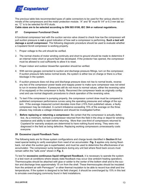
The previous table lists recommended types of cable connectors to be used for the various electric terminals<br />
of the compressors and the motor protection module. “A” and “B” must fit 1/4" or 6.3 mm tab sizes.<br />
“C” is to be selected for #10 studs.<br />
Cable sizes are to be selected according to DIN ISO 0100, IEC 364 or national regulations.<br />
27 Compressor Functional Check<br />
A functional compressor test with the suction service valve closed to check how low the compressor will<br />
pull suction pressure is not a good indication of how well a compressor is performing. Such a test will<br />
damage a scroll compressor. The following diagnostic procedure should be used to evaluate whether<br />
a Copeland <strong>Scroll</strong> compressor is working properly.<br />
1. Proper voltage to the unit should be verified.<br />
2. The normal checks of motor winding continuity and short to ground should be made to determine if<br />
an internal motor short or ground fault has developed. If the protector has opened, the compressor<br />
must be allowed to cool sufficiently to allow it to reset.<br />
3. Proper indoor and outdoor blower/fan operation should be verified.<br />
4. With service gauges connected to suction and discharge pressure fittings, turn on the compressor.<br />
If suction pressure falls below normal levels, the system is either low on charge or there is a flow<br />
blockage in the system.<br />
5. If suction pressure does not drop and discharge pressure does not rise to normal levels, reverse<br />
any two of the compressor power leads and reapply power to make sure compressor was not wired<br />
to run in reverse direction. If pressures still do not move to normal values, either the reversing valve<br />
(if so equipped) or the compressor is faulty. Reconnect the compressor leads as originally configured<br />
and use normal diagnostic procedures to check operation of the reversing valve.<br />
6. To test if the compressor is pumping properly, the compressor current draw must be compared to<br />
published compressor performance curves using the operating pressures and voltage of the system.<br />
If the average measured current deviates more than ±15% from published values, a faulty<br />
compressor may be indicated. A current imbalance exceeding 15% of the average on the three<br />
phases may indicate a voltage imbalance and should be investigated further.<br />
7. Before replacing or returning a compressor: Be certain that the compressor is actually defective.<br />
As a minimum, recheck a compressor returned from the field in the shop or depot for winding<br />
resistance and ability to start before returning. More than one-third of compressors returned to<br />
Copeland for warranty analysis are determined to have nothing found wrong. They were misdiagnosed<br />
in the field as being defective. Replacing working compressors unnecessarily costs<br />
everyone.<br />
28 Excessive Liquid Floodback Tests<br />
The following tests are for those system configurations and charge levels identified in Section 8 that<br />
need special testing to verify exemption from need of an accumulator. Fig. 3 applies only during floodback,<br />
not when the suction gas is superheated, and must be used to determine the effectiveness of an<br />
accumulator. The compressor sump temperature during any unit test where flood back occurs must<br />
remain within the "safe zone" shown in Fig. 3.<br />
To test for excessive continuous liquid refrigerant floodback, it is necessary to operate the system<br />
in a test room at conditions where steady state floodback may occur (low ambient heating operation).<br />
Thermocouples should be attached with glue or solder to the center of the bottom shell and to the suction<br />
and discharge lines approximately 15 cm from the shell. These thermocouples should be insulated<br />
from the ambient air with Permagum ® or other thermal insulation to be able to record true shell and line<br />
temperatures. If the system is designed to be field charged, it should be overcharged by 15% in this test<br />
to simulate overcharging commonly found in field installations.<br />
C6.2.2/0701/E 13