A/C Scroll Compressors ZR 90 K4*.....ZR 300 KC*
A/C Scroll Compressors ZR 90 K4*.....ZR 300 KC*
A/C Scroll Compressors ZR 90 K4*.....ZR 300 KC*

Create successful ePaper yourself
Turn your PDF publications into a flip-book with our unique Google optimized e-Paper software.
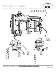
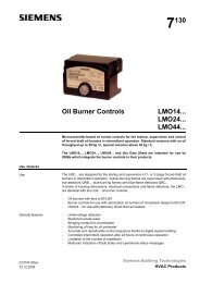
34 Shut-off Valves and Adaptors<br />
(1) - pressure control connection<br />
(2) - gauge connection<br />
A<br />
B<br />
C<br />
Fig. 14: Shut-off Valves and Adaptors<br />
The <strong>Scroll</strong> compressors can be delivered with brazing connections (BOM 522) or in Rotalock connection<br />
(BOM 551).<br />
Rotalock type shut-off valves can fit compressors with Rotalock connections or brazed connection (by<br />
the mean of Rotalock adaptors “C”). Rotalock-shut-off valves are available for the suction as well as the<br />
discharge side (see Spare Parts List “<strong>ZR</strong>”).<br />
Using adaptor “A” and “B” in either straight or angled form provides a way to convert a Rotalock into a<br />
brazing connection (see Spare Parts List “<strong>ZR</strong>”).<br />
For proper torque’s, which have to be applied see table in Section 33.<br />
35 Unbrazing System Components<br />
Caution! Before opening a system it is important to remove all refrigerant from both the high and low<br />
side. If the refrigerant charge is removed from a scroll-equipped unit by bleeding the high side only, it is<br />
possible for the scrolls to seal, preventing pressure equalization through the compressor. This may<br />
leave the low side shell and suction line tubing pressurized. If a brazing torch is then applied to the low<br />
side while the low side shell and suction line contains pressure, the pressurized refrigerant and oil mixture<br />
could ignite when it escapes and contacts the brazing flame. To prevent this occurrence, it is important<br />
to check both the high and low side with manifold gauges before unbrazing. Instructions should<br />
be provided in appropriate product literature and assembly (line repair) areas. If compressor removal is<br />
required, the compressor should be cut out of system rather than unbrazed. See Fig. 13 for proper<br />
compressor removal procedure.<br />
36 Compressor Replacement<br />
In the case of a motor burn, the majority of contaminated oil will be removed with the compressor. The<br />
rest of the oil is cleaned through use of suction and liquid line filter dryers. A 100% activated alumina<br />
suction filter drier is recommended but must be removed after 72 hours. It is highly recommended<br />
that the suction accumulator be replaced if the system contains one. This is because the accu-<br />
C6.2.2/0701/E 17