Product Design Guide - Diodes, Inc.
Product Design Guide - Diodes, Inc.
Product Design Guide - Diodes, Inc.

You also want an ePaper? Increase the reach of your titles
YUMPU automatically turns print PDFs into web optimized ePapers that Google loves.
<strong>Product</strong> Packaging Information<br />
SUGGESTED PAD LAYOUT<br />
Based on IPC-7351A<br />
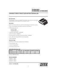
Figure 1<br />
Dimensions<br />
DFN1006-2 /<br />
DFN1006H4-2<br />
MiniMELF MELF SOD-323 SOD-123 SOD-523 SMA SMB SMC<br />
Z 1.1 4.8 6.3 3.75 4.9 2.3 6.5 6.7 9.3<br />
G 0.3 2.1 3.3 1.05 2.5 1.1 1.5 1.8 4.4<br />
X 0.7 1.7 2.7 0.65 0.7 0.8 1.7 2.3 3.3<br />
Y 0.4 1.3 1.5 1.35 1.2 0.6 2.5 2.5 2.5<br />
C 0.7 3.5 4.8 2.40 3.7 1.7 4.0 4.3 6.8<br />
C<br />
X<br />
Y<br />
G<br />
Z<br />
Fig. 1<br />
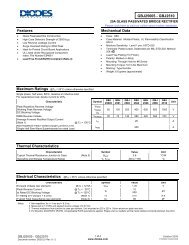
Figure 2<br />
Dimensions<br />
DFN1006-3 / DFN1006H4-3<br />
Z 1.1<br />
G1 0.3<br />
G2 0.2<br />
X 0.7<br />
X1 0.25<br />
Y 0.4<br />
C 0.7<br />
C<br />
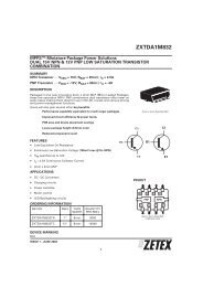
Figure 3<br />
Dimensions<br />
DFN1411-3<br />
Z 1.38<br />
G1 0.15<br />
G2 0.15<br />
X 0.95<br />
X1 0.75<br />
X2 0.40<br />
Y 0.75<br />
C 0.76<br />
X 1<br />
C<br />
X<br />
G2<br />
X2<br />
X1<br />
G2<br />
X<br />
Y<br />
G1<br />
Y<br />
G1<br />
Z<br />
Z<br />
Fig. 2<br />
Fig. 3<br />
Appendix 24<br />
ALL DIMENSIONS ARE NOMINAL VALUES SHOWN IN MILLIMETERS<br />
Note: The suggested land pattern dimensions have been provided for reference only, as actual pad layouts may vary depending on<br />
application. These numbers may be modified based on user equipment capability or fabrication criteria. A more robust pattern may be desired<br />
for wave soldering and is calculated by adding 0.2 mm to the ‘Z’ dimension. For further information, please reference document IPC-7351A,<br />
Naming Convention for Standard SMT Land Patterns, and for International grid details, please see document IEC, Publication 97.<br />
All data is subject to change. Please check our datasheets at www.diodes.com for updates.