A 25.6 W 13.56 MHz Wireless Power Transfer System ... - IEEE Xplore
A 25.6 W 13.56 MHz Wireless Power Transfer System ... - IEEE Xplore
A 25.6 W 13.56 MHz Wireless Power Transfer System ... - IEEE Xplore

Create successful ePaper yourself
Turn your PDF publications into a flip-book with our unique Google optimized e-Paper software.
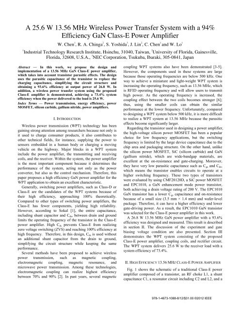
A <strong>25.6</strong> W <strong>13.56</strong> <strong>MHz</strong> <strong>Wireless</strong> <strong>Power</strong> <strong>Transfer</strong> <strong>System</strong> with a 94%<br />
Efficiency GaN Class-E <strong>Power</strong> Amplifier<br />
W. Chen 1 , R. A. Chinga 2 , S. Yoshida 3 , J. Lin 2 , C. Chen 1 and W. Lo 1<br />
1<br />
Industrial Technology Research Institute, Hsinchu, 31040, Taiwan, 2 University of Florida, Gainesville,<br />
Florida, 32608, U.S.A., 3 NEC Corporation, Tsukuba, Ibaraki, 305-0841, Japan<br />
Abstract — In this work, we propose the design and<br />
implementation of a <strong>13.56</strong> <strong>MHz</strong> GaN Class-E power amplifier,<br />
which takes into account transistor parasitic effects. The design<br />
uses the parasitic capacitance of the transistor to replace the<br />
charging capacitance, simplifying the circuit structure and<br />
obtaining a 93.6% efficiency at output power of 26.8 W. In<br />
addition, a wireless power transfer system using the proposed<br />
Class-E amplifier is demonstrated, achieving a 73.4% system<br />
efficiency when the power delivered to the load is <strong>25.6</strong> W.<br />
Index Terms — <strong>Power</strong> transmission, energy efficiency, power<br />
MOSFET, silicon carbide, gallium nitride, power amplifiers.<br />
I. INTRODUCTION<br />
<strong>Wireless</strong> power transmission (WPT) technology has been<br />
gaining strong attention among researchers because not only is<br />
it used to charge consumer products, it also contributes to<br />
other technical fields, for instance, supplying the power to<br />
sensors embedded in a human body or charging a moving<br />
vehicle on the highway. Major blocks in a WPT system<br />
include the power amplifier, the transmitting and receiving<br />
coils, and the receiver. Within the system, the power amplifier<br />
is the most important component because it determines the<br />
performance of the system, acting not only as the power<br />
converter, but also as the control mechanism. Therefore, this<br />
paper proposes a high efficiency GaN power amplifier for the<br />
WPT application to obtain an excellent characteristic.<br />
Generally, switching power amplifiers, such as Class-D or<br />
Class-E are the candidates of the WPT systems because of<br />
their high efficiency, approaching 100% theoretically.<br />
Compared to other types of switching power amplifiers, the<br />
Class-E has fewer components, yielding high reliability.<br />
However, according to Sokal [1], the entire capacitance,<br />
including shunt capacitor and C ds , between drain and ground<br />
limits the operating frequency of the transistor in the Class-E<br />
power amplifier. High C ds prevents Class-E from realizing<br />
zero voltage switching (ZVS) and reaching 100% efficiency at<br />
high frequency. Therefore, in this design, C ds is used without<br />
an additional shunt capacitor from the drain to ground,<br />
simplifying the circuit structure while keeping the same<br />
performance.<br />
Several methods have been proposed to achieve wireless<br />
power transmission, such as magnetic coupling,<br />
electromagnetic coupling, magnetic resonance, and<br />
microwave power transmission. Among these technologies,<br />
electromagnetic coupling can realize highest efficiency<br />
between 70% and 90% [2]. In past years, several magnetic<br />
coupling WPT systems also have been demonstrated [3-5].<br />
However, the components used in these systems are large<br />
because those operating frequencies are below 500 kHz. One<br />
way to achieve a miniature and light-weight WPT system is<br />
increasing the operating frequency, such as <strong>13.56</strong> <strong>MHz</strong>, which<br />
is RFID operating frequency and will allow users to transmit<br />
high power. As the operating frequency is increased, the<br />
coupling effect between the two coils becomes stronger [6];<br />
thus, using the smaller coils can obtain the similar<br />
performance at the lower frequency. Unfortunately, compared<br />
to designing a WPT system below 500 kHz, it is more difficult<br />
to realize a WPT system at <strong>13.56</strong> <strong>MHz</strong> because the parasitic<br />
effects become significantly larger.<br />
Regarding the transistor used in designing a power amplifier,<br />
the high-voltage silicon power MOSFET has been a popular<br />
choice for low frequency applications, but the switching<br />
frequency is limited by the large device capacitance due to the<br />
chip area and packaging structure. On the other hand, unlike<br />
the silicon power MOSFET, SiC (silicon carbide) and GaN<br />
(gallium nitride), which are wide-bandgap materials, are<br />
excellent at the on-resistance and gate-charging. Moreover,<br />
they have very low parasitic capacitance such as C gs and C ds ,<br />
which means the transistor enables circuits to operate at a<br />
higher switching frequency. These two types of transistors<br />
were evaluated by using CMF20120D, a SiC power MOSFET<br />
and EPC1010, a GaN enhancement mode power transistor,<br />
both achieving a drain voltage rating of 200 V. The EPC1010<br />
GaN transistor has a lower C gs capacitance and on-resistance<br />
because of a small size (3.5 mm × 1.4 mm) and wafer-level<br />
package. Therefore, it can have a higher efficiency and lower<br />
gate-driving power. As a result, the EPC1010 GaN transistor<br />
was selected for the Class-E power amplifier in this work.<br />
A 26.8 W <strong>13.56</strong> <strong>MHz</strong> GaN power amplifier with a 93.6%<br />
efficiency was designed and measured. This result is described<br />
in section II. The discussion of the experiment and gate<br />
biasing voltage condition are also presented. Section III<br />
demonstrates the WPT system consisting of the proposed<br />
Class-E power amplifier, coupling coils, and rectifier circuit.<br />
The WPT system delivers <strong>25.6</strong> W to the receiver load with a<br />
system efficiency of 73.4%.<br />
II. HIGH EFFICIENCY <strong>13.56</strong> MHZ CLASS-E POWER AMPLIFIER<br />
Fig. 1 shows the schematic of a traditional Class-E power<br />
amplifier composed of a transistor, an RF choke L1, a shunt<br />
capacitance C1, a resonator circuit including C2 and L2, and a<br />
978-1-4673-1088-8/12/$31.00 ©2012 <strong>IEEE</strong>
load resistor R. Those component values can be calculated by<br />
the equations listed in [1]. In the design, C ds of the GaN<br />
transistor is used to replace C1, simplifying the circuit<br />
structure while keeping the same performance. The<br />
component values are L1 = 50 µH, C2 = 690 pF, L2 = 0.3 µH,<br />
and R = 13 Ω. For the gate-driving circuit design, a K50-HC<br />
oscillator is used to generate a <strong>13.56</strong> <strong>MHz</strong> clock, which is then<br />
amplified by an IXD1502 gate driver to drive the GaN<br />
transistor.<br />
TABLE 1<br />
THREE <strong>13.56</strong> MHZ GAN CLASS-E POWER AMPLIFIERS<br />
Output power (W) Drain Efficiency (%)<br />
[7] 1.8 78<br />
[8] 13.4 91<br />
This work 26.8 93.6<br />
Fig. 1. Schematic diagram of the Class-E <strong>Power</strong> Amplifier.<br />
The waveforms and power delivered to load resistor R were<br />
measured by using a current probe (Tektronix X004062),<br />
voltage probes (Tektronix P2220), and an oscilloscope<br />
(Tektronix TDS2004B). Fig. 2 displays the voltage waveforms<br />
at the drain and input clock signal at the gate when the supply<br />
voltage VDD is 25 V. The output current and voltage<br />
waveform at load resistor R are shown in Fig. 3. If R is an<br />
ideal resistor, the current and voltage waveform should be inphase.<br />
However, at <strong>13.56</strong> <strong>MHz</strong>, this resistor has parasitic<br />
capacitance and inductance, causing 11 degrees phase<br />
difference between the two waveforms.<br />
Fig. 4 demonstrates the drain voltage versus the efficiency<br />
and output power. Because the power consumption of the<br />
gate-driving circuit is 370 mW, the efficiency of the circuit at<br />
low output power is relatively small. If the C gs of the transistor<br />
is larger, the gate-driving circuit consumes more current to<br />
drive the transistor. Therefore, choosing a transistor with a<br />
low C gs is very important, especially when the output power is<br />
not high. In this design, without considering the power<br />
consumption of the gate-driving circuit, the highest output<br />
power at the load is 26.8 W with a drain efficiency of 93.6%<br />
when VDD is 27 V and the gate-driving circuit supply voltage<br />
is 5 V. Fig. 4 also indicates that the GaN transistor is more<br />
efficient when generating high power. For instance, the drain<br />
efficiency increases 5.4% when the output power is from 9.8<br />
W@VDD = 17 V to 26.8 W@VDD = 27 V. Because a heat<br />
sink was not added to the circuit, 27 V is the highest testing<br />
voltage in this study. The relation among the gate-driving<br />
circuit supply voltage, the output power, and efficiency is<br />
displayed in Fig. 5. The gate-driving circuit supply voltage<br />
range is from 4 to 6 V, while the VDD is set to 25 V. This<br />
graph shows the circuit can perform more efficiently when it<br />
is supplied by a high gate-driving voltage. However, 6 V is the<br />
limitation at the input of the GaN transistor, and therefore 5 V<br />
is used to prevent possible damage.<br />
Fig. 2. Drain and gate waveforms.<br />
Fig. 3. Voltage and current waveforms at load resistor R.<br />
Fig. 4. Output power (solid squares), drain efficiency (hollow<br />
circles), and total efficiency (hollow triangles) versus drain supply<br />
voltage. Total efficiency calculation includes power consumption in<br />
the gate-driving circuit.<br />
Table 1 lists the results of two previously published similar<br />
works as well as this work that shows higher output power<br />
with a higher drain efficiency.<br />
III. DEMONSTRATION OF <strong>13.56</strong> MHZ WPT SYSTEM<br />
Fig.6 illustrates the schematic diagram of the WPT system,<br />
including the proposed Class-E power amplifier, coupling<br />
978-1-4673-1088-8/12/$31.00 ©2012 <strong>IEEE</strong>
Fig. 7. Photograph of the WPT system.<br />
Fig. 5. Output power (solid squares), drain efficiency (hollow<br />
circles), and total efficiency (hollow triangles) versus supply voltage<br />
of gate-driving circuit. Total efficiency calculation includes power<br />
consumption in the gate-driving circuit.<br />
coils, rectifier circuit, and matching networks. The coils,<br />
consisting of two concentric coils of the same length, designed<br />
by magnetic coupling method, were utilized to transfer a <strong>13.56</strong><br />
<strong>MHz</strong> signal generated from the Class-E power amplifier. The<br />
mutual inductance between the coils is 0.49 µH when L3 is<br />
0.92 µH with a parasitic resistance of 4.8 Ω; and L4 is 0.56<br />
µH with a parasitic resistance of 2.6 Ω, measured at 13 <strong>MHz</strong>.<br />
After the <strong>13.56</strong> <strong>MHz</strong> signal couples from L3 to L4, the fullbridge<br />
rectifier, composed of four SK310A diodes and a<br />
capacitor C5 of 68 uF, rectifies the AC signal to DC power.<br />
[4] explains the four topologies for a single-element<br />
impedance transformation network, and the series-series<br />
topology, realized by C3 of 132 pF and C4 of 150 pF, was<br />
selected for the WPT system to achieve the maximum power<br />
transmission. Fig. 8 demonstrates the characteristic of the<br />
WPT system with different load resistances. When Rload is<br />
350 Ω, the system achieves 73.4% efficiency when the power<br />
delivered to Rload is <strong>25.6</strong> W.<br />
IV. CONCLUSION<br />
The proposed Class-E power amplifier achieves 26.8 W<br />
output power with an efficiency of 93.6% at <strong>13.56</strong> <strong>MHz</strong>. A<br />
WPT system using this amplifier achieves power delivery of<br />
<strong>25.6</strong> W with a 73.4% system efficiency. This demonstrates<br />
that the GaN transistor is a suitable choice for a WPT system<br />
at this frequency.<br />
Fig. 6. Schematic diagram of the WPT system.<br />
Fig. 8. <strong>Power</strong> delivered to Rload (solid squares), drain efficiency<br />
(hollow circles), and system efficiency (hollow triangles) versus<br />
Rload. <strong>System</strong> efficiency calculation includes power consumption in<br />
the gate-driving circuit.<br />
REFERENCES<br />
[1] N. O. Sokal and A. D. Sokal, "Class E-A new class of highefficiency<br />
tuned single-ended switching power amplifiers,"<br />
Solid-State Circuits, <strong>IEEE</strong> Journal of, vol. 10, pp. 168-176,<br />
1975.<br />
[2] H. Shoki, "Issues and initiatives for practical use of wireless<br />
power transmission technologies in Japan," in Microwave<br />
Workshop Series on Innovative <strong>Wireless</strong> <strong>Power</strong> Transmission:<br />
Technologies, <strong>System</strong>s, and Applications (IMWS), 2011 <strong>IEEE</strong><br />
MTT-S International, 2011, pp. 87-90.<br />
[3] J. J. Casanova, et al., "Design and Optimization of a Class-E<br />
Amplifier for a Loosely Coupled Planar <strong>Wireless</strong> <strong>Power</strong><br />
<strong>System</strong>," Circuits and <strong>System</strong>s II: Express Briefs, <strong>IEEE</strong><br />
Transactions on, vol. 56, pp. 830-834, 2009.<br />
[4] L. Zhen Ning, et al., "Method of Load/Fault Detection for<br />
Loosely Coupled Planar <strong>Wireless</strong> <strong>Power</strong> <strong>Transfer</strong> <strong>System</strong> With<br />
<strong>Power</strong> Delivery Tracking," Industrial Electronics, <strong>IEEE</strong><br />
Transactions on, vol. 57, pp. 1478-1486, 2010.<br />
[5] L. Zhen Ning, et al., "Design and Test of a High-<strong>Power</strong> High-<br />
Efficiency Loosely Coupled Planar <strong>Wireless</strong> <strong>Power</strong> <strong>Transfer</strong><br />
<strong>System</strong>," Industrial Electronics, <strong>IEEE</strong> Transactions on, vol. 56,<br />
pp. 1801-1812, 2009.<br />
[6] J. Garnica, et al., "High efficiency midrange wireless power<br />
transfer system," in Microwave Workshop Series on Innovative<br />
<strong>Wireless</strong> <strong>Power</strong> Transmission: Technologies, <strong>System</strong>s, and<br />
Applications (IMWS), 2011 <strong>IEEE</strong> MTT-S International, 2011, pp.<br />
73-76.<br />
[7] H. Uchiyama, et al., "Consideration of impact of GaN HEMT<br />
for class E amplifier," in TENCON 2010 - 2010 <strong>IEEE</strong> Region 10<br />
Conference, 2010, pp. 1780-1783.<br />
[8] W. Saito, et al., "Demonstration of <strong>13.56</strong>-<strong>MHz</strong> class-E amplifier<br />
using a high-Voltage GaN power-HEMT," Electron Device<br />
Letters, <strong>IEEE</strong>, vol. 27, pp. 326-328, 2006.<br />
978-1-4673-1088-8/12/$31.00 ©2012 <strong>IEEE</strong>