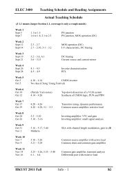
Lect. 20: Dielectric Resonators & Excitation of Resonators ⢠Made of ...
Lect. 20: Dielectric Resonators & Excitation of Resonators ⢠Made of ...
Lect. 20: Dielectric Resonators & Excitation of Resonators ⢠Made of ...

Create successful ePaper yourself
Turn your PDF publications into a flip-book with our unique Google optimized e-Paper software.
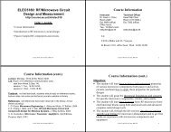
<strong>Lect</strong>. <strong>20</strong>: <strong>Dielectric</strong> <strong>Resonators</strong> &<br />
<strong>Excitation</strong> <strong>of</strong> <strong>Resonators</strong><br />
<strong>Dielectric</strong> Resonator --- raise your high-Q<br />
What is it? A piece <strong>of</strong> high-dielectric constant material, usually in the<br />
shape <strong>of</strong> a disc, that functions as a miniature microwave resonator.<br />
• <strong>Made</strong> <strong>of</strong> low-loss high dielectric constant materials.<br />
• High dielectric constants ensures that most <strong>of</strong> the field is<br />
confined within the dielectric.<br />
• Advantages: small size, low price, excellent integrability with<br />
microwave integrated circuits.<br />
• Conductor loss is absent, but dielectric loss increases with<br />
dielectric constant.<br />
• Qs <strong>of</strong> up to several thousand can be achieved.<br />
How does it work? The dielectric<br />
element functions as a resonator<br />
because <strong>of</strong> the internal reflection <strong>of</strong><br />
electromagnetic waves at the high<br />
dielectric constant material/air<br />
boundary. This results in<br />
confinement <strong>of</strong> energy within, and in<br />
the vicinity <strong>of</strong>, the dielectric<br />
material, which, therefore, forms a<br />
resonant structure.<br />
ELEC344, Kevin Chen, HKUST 1<br />
ELEC344, Kevin Chen, HKUST 2<br />
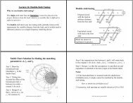
Why use it? High-Q tuning network enhances the stability <strong>of</strong><br />
oscillators. The Q <strong>of</strong> a resonant network using lumped elements or<br />
microstrip lines and stubs is typically limited to a few hundred.<br />
Usually coupled to an oscillator circuit by positioning in close<br />
proximity to a microstrip line.<br />
Waveguide cavity resonators can<br />
have Qs <strong>of</strong> 10,000 or more, they are<br />
not well-suited for integration in<br />
miniature microwave integrated<br />
circuitry. Metal cavities also have<br />
significant frequency shift caused by<br />
dimensional expansion due to<br />
temperature variation.<br />
<strong>Dielectric</strong> resonators can replace traditional, high-Q waveguide cavity<br />
resonators in most applications, especially in microwave integrated<br />
circuit (MIC) and monolithic microwave integrated circuit (MMIC)<br />
structures. The resonator is small, lightweight, high-Q, temperaturestable,<br />
low-cost and easy-to-use. A typical Q exceeds 10,000 at 4<br />
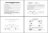
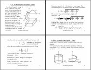
Cylindrical <strong>Dielectric</strong> Resonator:<br />
Dominant Mode: TE 01δ<br />
Where δ = 2L/λg (
Approximated solution (10% error):<br />
In the dielectric region, |z| < L/2, the propagation<br />
constant is real:<br />
2<br />
2 2<br />
2 ⎛ p01<br />
⎞<br />
β = ε r<br />
k0 − kc<br />
= ε<br />
rk0<br />
− ⎜ ⎟<br />
⎝ a ⎠<br />
In the air region, |z| > L/2, the propagation constant will<br />
be imaginary, so we write:<br />
2<br />
2 2 ⎛ p01<br />
⎞ 2<br />
α = jβ<br />
= kc − k0<br />
= ⎜ ⎟ − k0<br />
⎝ a ⎠<br />
Implementing the boundary condition leads to<br />
Q-factor:<br />
tan β L / 2 = α / β<br />
Q d<br />
=<br />
1<br />
tanδ<br />
Numerically solving this<br />
equation can result in the<br />
finding <strong>of</strong> resonant<br />
frequencies <strong>of</strong> the TE 01δ<br />
mode.<br />
ELEC344, Kevin Chen, HKUST 5<br />
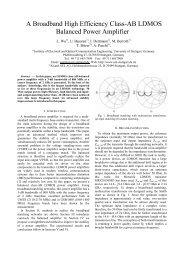
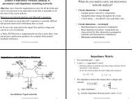
<strong>Excitation</strong> <strong>of</strong> <strong>Resonators</strong><br />
Common coupling<br />
techniques:<br />
1. Gap coupling<br />
2. Aperture coupling<br />
Gap coupling<br />
aperture coupling<br />
feed coupling<br />
Microstrip<br />
feedline coupling<br />
Waveguide<br />
antenna coupling<br />
ELEC344, Kevin Chen, HKUST 6<br />
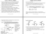
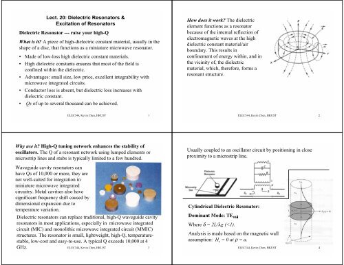
Critical Coupling<br />
- a resonator matched to a feedline at the resonance<br />
frequency: to obtain maximum power transfer between a<br />
resonator and a feedline<br />
Consider this: a series<br />
resonant circuit coupled<br />
to a feedline<br />
Z in<br />
≈ R + j2L∆ω<br />
≈ R(1<br />
+<br />
The unloaded Q is<br />
At resonance,<br />
we have<br />
ω0 Q =<br />
L<br />
R<br />
Z = Z<br />
* = in<br />
R<br />
0<br />
∆ω<br />
j2Q<br />
)<br />
ω 0<br />
Then<br />
0L<br />
Q =<br />
ω<br />
Z0<br />
ω L<br />
Q e<br />
= 0<br />
= Q<br />
Z<br />
ELEC344, Kevin Chen, HKUST 7<br />
0<br />
the external Q<br />
Coupling Coefficient: g<br />
Q ⎧Z0<br />
/ R for series resonator<br />
g = = ⎨<br />
Qe<br />
⎩R<br />
/ Z0<br />
for parallel resonator<br />
Three different coupling situation:<br />
(1) g < 1, undercoupled; (2) g = 1, critically coupled;<br />
(3) g > 1, overcoupled<br />
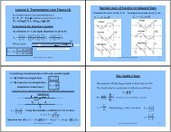
A Gap-Coupled Microstrip Resonator<br />
λ/2<br />
A λ/2 open-circuited microstrip<br />
resonator is coupled to a microstrip<br />
feedline.<br />
ELEC344, Kevin Chen, HKUST 8
Equivalent circuit <strong>of</strong> the gap-coupled microstrip resonator<br />
The normalized input impedance seen by the feedline is<br />
Z [(1/ ωC)<br />
+ Z0<br />
cot βl]<br />
tan βl<br />
+ bc<br />
z = = − j<br />
= − j<br />
Z<br />
Z<br />
b tan βl<br />
0<br />
0<br />
Where b c =Z 0 ωC is the normalized susceptance <strong>of</strong> the coupling<br />
capacitor, C.<br />
c<br />
When does the resonance occur?<br />
z = 0<br />
In practice,<br />
b c<br />