AMACO® Standard Economy Electric Kiln EC-55
AMACO® Standard Economy Electric Kiln EC-55
AMACO® Standard Economy Electric Kiln EC-55

You also want an ePaper? Increase the reach of your titles
YUMPU automatically turns print PDFs into web optimized ePapers that Google loves.
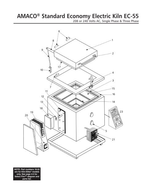
AMACO ® <strong>Standard</strong> <strong>Economy</strong> <strong>Electric</strong> <strong>Kiln</strong> <strong>EC</strong>-<strong>55</strong><br />
208 or 240 Volts AC, Single Phase & Three Phase<br />
6<br />
8<br />
1<br />
9<br />
2<br />
10<br />
17<br />
4<br />
3<br />
12<br />
11<br />
7<br />
15<br />
16<br />
13<br />
14<br />
20<br />
19<br />
18<br />
23<br />
5<br />
21<br />
NOTE: Part numbers 18-22<br />
are for <strong>Kiln</strong>-Sitter ® models<br />
only. See page 4-5 for<br />
Select Fire diagram and<br />
parts list.
General Information<br />
The AMACO ® <strong>EC</strong>-<strong>55</strong> <strong>Economy</strong> kiln has a maximum attainable temperature of Cone 03 (2019ºF, 1104ºC). The <strong>EC</strong>-<strong>55</strong> is available with<br />
manual control switches or the Select Fire Computer Control for precise control, convenience, and consistent results firing after<br />
firing. During every firing, pyrometric cones should be placed in the kiln so that they can be viewed through the peephole(s).<br />
This booklet contains a wiring diagram for the <strong>EC</strong>-<strong>55</strong> kiln, Select Fire Controller (single and three phase) and a parts list with<br />
accompanying drawing for the <strong>EC</strong>-<strong>55</strong> and Select Fire. Before installing the kiln, consult these diagrams for recommendations on<br />
electric service, fuses, etc.<br />
Also included with this booklet is an AMACO ® <strong>Electric</strong> <strong>Kiln</strong>s Installation/Operation/Maintenance manual, which includes important<br />
information about selecting a location for your kiln, firing guidelines, do-it-yourself instructions for replacing elements, and complete<br />
programming and operating instructions for the Select Fire Controller.<br />
Operating Information for Manual Models with <strong>Kiln</strong>-Sitter ®<br />
The Amaco ® <strong>EC</strong>-<strong>55</strong> kiln is equipped with a fused safety switch box and three toggle switches. A pilot light indicates when the kiln<br />
is operating.<br />
Close kiln door and latch securely before firing. Turn safety switch to “ON”, place the appropriate cone in the <strong>Kiln</strong>-Sitter ® , and push<br />
the plunger button. NOTE: If the kiln is equipped with a <strong>Kiln</strong>Vent, it must be turned on prior to firing.<br />
The toggle switches operate as follows:<br />
LOW: Turn on any switch<br />
MEDIUM: Turn on any two switches<br />
HIGH: Turn on all three switches<br />
The time required for firing will depend on the temperature to be attained, the number of objects being fired, and electric current<br />
fluctuations. Approximate cycle times are as follows:<br />
LOW: approximately 1 /2 hour<br />
MEDIUM: approximately 1 /2 hour<br />
HIGH: until desired temperature is reached<br />
When firing time has been completed, turn off all switches and allow the kiln to cool overnight. If glazed pieces are removed from the<br />
kiln when the pieces are too hot, crazing may result due to sudden cooling. NOTE: <strong>Kiln</strong>s equipped with a <strong>Kiln</strong>Vent will cool faster.<br />
Installation of <strong>Kiln</strong><br />
Place kiln at least 18 inches from any existing wall at the sides and back. Connect kiln to an electric circuit which corresponds to that<br />
stamped on the kiln name plate. No. 6 gauge wire or larger should run from the power supply to the fused safety switch box on the<br />
kiln. 35 ampere fuses are required for single phase models, 20 ampere fuses for three phase models.<br />
KILN SP<strong>EC</strong>IFICATIONS <strong>EC</strong>-<strong>55</strong><br />
(Single and three phase unless otherwise noted)<br />
Voltage ................................................................................................................208 or 240 volts AC only<br />
Amp Rating ....................28.7 at 208V, 27.1 at 240V (single phase), 16.5 at 208 or 240V (three phase)<br />
Kilowatt Rating ......................................................................................................................................6.5<br />
Power Cord........................................50 amp with NEMA 6-50 plug (single phase) or NEMA 15-50 plug<br />
(three phase) for Select Fire models. Direct wire for non-SF models.<br />
Firing Speed Control ......................................Three Toggle Switches or Select Fire Computer Control<br />
Maximum Temperature......................................................................................................2019°F, 1104°C<br />
Firing Chamber Dimensions (W x D x H) ..........................................................................18" x 18" x 18"<br />
Firing Chamber Area ..........................................................................................................3.38 cubic feet<br />
Exterior Dimensions (W x D x H) ..................................................................................41"* x 29 1 ⁄2" x 32"<br />
Elements..........................................................................................................................Three Wire Coils<br />
Shipping Weight ............................................................................................................................404 lbs.<br />
*Width dimension includes Select Fire<br />
Ordering Replacement Parts: when ordering replacement parts for this kiln, be sure to specify<br />
the Model Number, Serial Number and Voltage.<br />
2
REPLACEMENT PARTS LIST<br />
AMACO ® STANDARD <strong>EC</strong>ONOMY EL<strong>EC</strong>TRIC KILN <strong>EC</strong>-<strong>55</strong><br />
DETAIL PART DESCRIPTION PARTS/<br />
NO. NO. KILN<br />
1 ....................29754R ............Lid Complete - No Hardware<br />
2 ....................28129H ............Lid Handle ..............................................................................................................................1<br />
3 ....................29278C ............Fiberfrax Rope ......................................................................................................................1<br />
4 ....................28153X ............Lid Latch ................................................................................................................................1<br />
5 ....................29025C ............Peephole Cover ....................................................................................................................3<br />
6 ....................28073H ............Hinge without pin....................................................................................................................4<br />
7 ....................28072G ............Hinge Pin................................................................................................................................2<br />
8 ....................29231B ............Spring Arm ............................................................................................................................2<br />
9 ....................29232C ............Spring ....................................................................................................................................2<br />
10....................29233D ............Spring Bracket........................................................................................................................2<br />
11....................29765G ............Cem-Fil ..................................................................................................................................1<br />
12....................28034M ............Insulator—P-3580 ..................................................................................................................6<br />
13 ....................28071F ............Terminal Lug—C10NPW ........................................................................................................6<br />
14....................29295H ............Element Coil 208V ................................................................................................................3<br />
14 ..................29296W ............Element Coil 230V ................................................................................................................3<br />
15....................29299A ............Brick, side terminal..............................................................................................................1 set<br />
15....................29781Y ............Brick, Bottom ......................................................................................................................1 set<br />
15 ....................29778F ............Brick, side finished ................................................................................................................6<br />
16....................29306H ............Side Insulation ......................................................................................................................4<br />
16....................29308K ............Bottom Insulation ..................................................................................................................1<br />
18 ..................28108W ............Safety Switch 60 Amp 3 Ph. (ITE JN 422C) - <strong>Kiln</strong>-Sitter ® models only ................................1<br />
19 ....................28063T ............Switch 20 Amp (Sierra 5022X) - <strong>Kiln</strong>-Sitter ® models only ......................................................3<br />
20....................28819R ............Pyrometer with Termocouple Set - <strong>Kiln</strong>-Sitter ® models only ..................................................1<br />
21....................28741B ............<strong>Kiln</strong> Sitter ® , LT-3 Model with Limit Timer, 208, 220/240 Volts, Single Phase<br />
<strong>Kiln</strong>-Sitter ® models only ..................................................................................................................1<br />
21....................28739Y ............<strong>Kiln</strong> Sitter ® with Limit Timer and Relay, 208, 220/240 Volts, Three Phase<br />
<strong>Kiln</strong>-Sitter ® models only ..................................................................................................................1<br />
24276H ............Relay for <strong>Kiln</strong> Sitter, Three Phase Only ............................................................................1<br />
* Fuse, Dual Element, 35 Amp ................................................................................................1<br />
23....................24122S ............Select Fire Control Box ......................................................................................................1<br />
OPTIONAL EQUIPMENT<br />
29976T ............<strong>Kiln</strong>Vent-Suspended Version, 115 Volt, 1.1 Amp................................................................1<br />
29968J ............Master <strong>Kiln</strong>Vent, 115 Volt, 1.1 Amp ..................................................................................1<br />
24122S ............Select Fire (Wall Mount), ....................................................................................................1<br />
24123T ............Select Fire (Wall Mount), Three Phase ................................................................................1<br />
11393E ............<strong>EC</strong>-<strong>55</strong> Furniture Kit #7 ......................................................................................................1<br />
*Available at hardware/home improvement stores.<br />
3
Three Relay, Single Phase<br />
SEL<strong>EC</strong>T FIRE <strong>Kiln</strong> Controller and Element<br />
Wiring Diagrams for <strong>EC</strong>-<strong>55</strong><br />
Warning:<br />
Disconnect power<br />
before servicing kiln.<br />
A<br />
Detail No. Part No. Description<br />
A............28847X ........Thermocouple<br />
B............24250P..........Control, Select Fire<br />
C, D, E ....24276H ........Relays<br />
F............24278K..........Transformer, Select Fire<br />
G ..........27749M ......Terminal Block, 60A, 3 Pole<br />
H............22134W ........Fuse Holder<br />
I..............27759A ........Power Cord, Single Phase<br />
J............24332C..........Current Sensor<br />
J<br />
F<br />
B<br />
Single Phase Element<br />
Wiring Diagram<br />
YELLOW<br />
G<br />
C<br />
YELLOW<br />
BLACK<br />
D<br />
I<br />
H<br />
BLACK<br />
WHITE<br />
E<br />
WHITE<br />
4
Three Relay, Three Phase<br />
SEL<strong>EC</strong>T FIRE <strong>Kiln</strong> Controller and Element<br />
Wiring Diagrams for <strong>EC</strong>-<strong>55</strong><br />
Warning:<br />
Disconnect power<br />
before servicing kiln.<br />
A<br />
Detail No. Part No. Description<br />
A............28847X ........Thermocouple<br />
B............24250P..........Control, Select Fire<br />
C, D, E ....24276H ........Relays<br />
F............24278K..........Transformer, Select Fire<br />
G ..........27749M ......Terminal Block, 60A, 3 Pole<br />
H............22134W ........Fuse Holder<br />
I..............28674D ........Power Cord, Three Phase<br />
J............24332C..........Current Sensor<br />
J<br />
F<br />
B<br />
Three Phase Element<br />
Wiring Diagram<br />
YELLOW<br />
G<br />
C<br />
YELLOW<br />
BLACK<br />
D<br />
I<br />
H<br />
BLACK<br />
WHITE<br />
E<br />
WHITE<br />
5
<strong>EC</strong>-<strong>55</strong> Single Phase 208-240V<br />
<strong>Kiln</strong>-Sitter ® and Switch Box<br />
Wiring Diagram<br />
18<br />
Fuse<br />
(See Page 3)<br />
Warning:<br />
Disconnect power before<br />
servicing kiln.<br />
21<br />
See pages 1 and 3 for parts information.<br />
6
<strong>EC</strong>-<strong>55</strong> Three Phase 208-240V<br />
<strong>Kiln</strong>-Sitter ® With Relay and Switch Box<br />
Wiring Diagram<br />
Warning:<br />
Disconnect power before<br />
servicing kiln.<br />
Relay<br />
(See Page 3)<br />
Fuse<br />
(See Page 3)<br />
18<br />
21<br />
See pages 1 and 3 for parts information.<br />
7
<strong>EC</strong>-<strong>55</strong> Single Phase 208-240V<br />
Infinite Switches and Elements Wiring Diagram<br />
<strong>EC</strong>-<strong>55</strong> Three Phase 208-240V<br />
Infinite Switches and Elements Wiring Diagram<br />
American Art Clay Co., Inc. • 6060 Guion Rd., Indianapolis, IN 46254<br />
(800) 374-1600 • www.amaco.com • Email: technicalsupport@amaco.com<br />
8<br />
Revised 11/12