spot welder - Harbor Freight Tools
spot welder - Harbor Freight Tools
spot welder - Harbor Freight Tools
Create successful ePaper yourself
Turn your PDF publications into a flip-book with our unique Google optimized e-Paper software.
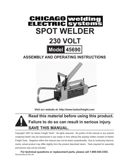
<strong>spot</strong> <strong>welder</strong><br />
230 volt<br />
Model 45690<br />
assembly and Operating Instructions<br />
Visit our website at: http://www.harborfreight.com<br />
Read this material before using this product.<br />
Failure to do so can result in serious injury.<br />
Save this manual.<br />
Copyright © 2001 by <strong>Harbor</strong> <strong>Freight</strong> <strong>Tools</strong> ® . All rights reserved. No portion of this manual or any artwork<br />
contained herein may be reproduced in any shape or form without the express written consent of <strong>Harbor</strong><br />
<strong>Freight</strong> <strong>Tools</strong>. Diagrams within this manual may not be drawn proportionally. Due to continuing improvements,<br />
actual product may differ slightly from the product described herein. <strong>Tools</strong> required for assembly<br />
and service may not be included.<br />
For technical questions or replacement parts, please call 1-800-444-3353.<br />
Revised Manual 02b, 09l
ITEM<br />
Electrical Input Requirements<br />
Rated Output<br />
SPECIFICATIONS TABLE<br />
DESCRIPTION<br />
230 Volt<br />
1.5 KVA @ 50% Duty Cycle<br />
Output Amps 5,500 +/- 10%<br />
Material Capacity<br />
Tong Length 6”<br />
1/8” Thick, Mild Steet<br />
Overall Dimensions 13” x 6” x 4.5”<br />
Net Weight<br />
23.5 Lbs.<br />
SAVE THIS MANUAL<br />
You will need this manual for the safety warnings and precautions, assembly,<br />
operating, inspection, maintenance, and cleaning procedures, parts list and assembly<br />
diagram. Keep your invoice with this manual. Write the invoice number on the inside<br />
of the front cover. Keep this manual and invoice in a safe and dry place for future<br />
reference.<br />
GENERAL SAFETY WARNINGS AND PRECAUTIONS<br />
1. KEEP WORK AREA CLEAN AND DRY. Cluttered, damp or wet work areas invite<br />
injuries.<br />
2. KEEP CHILDREN AWAY FROM WORK AREA. Do not allow children to handle this<br />
product.<br />
3. STORE IDLE EQUIPMENT. When not in use, tools and equipment should be stored<br />
in a dry location to inhibit rust. Always lock up tools and equipment and keep out of<br />
reach of children.<br />
4. DO NOT USE THIS PRODUCT IF UNDER THE INFLUENCE OF ALCOHOL OR<br />
DRUGS. Read warning labels on prescriptions to determine if your judgment or<br />
reflexes are impaired while taking drugs. If there is any doubt, do not attempt to use<br />
this product.<br />
5. USE EYE, HEARING, BREATHING, AND HAND PROTECTION. Wear an ANSI<br />
approved welding helmet/goggles with shaded lens, hearing protectors, breathing<br />
respirator, and welding gloves when using this product. ANSI approved welding<br />
helmet/goggles with shaded lens, hearing protectors, breathing respirators,and<br />
welding gloves are available from <strong>Harbor</strong> <strong>Freight</strong> <strong>Tools</strong>.<br />
6. DRESS SAFELY. Sparks and hot metal can injure. Always wear body protection.<br />
Non-skid footwear or safety shoes should be used when working with this product.<br />
Do not wear loose clothing or jewelry as they can become caught in moving parts.<br />
Wear a protective hair covering to prevent long hair from becoming caught in moving<br />
parts. If wearing a long-sleeve shirt, roll sleeves up above elbows.<br />
7. INDUSTRIAL APPLICATIONS MUST FOLLOW OSHA REQUIREMENTS.<br />
SKU 45690 PAGE 2<br />
Rev 02b, 03h, 09l
8. DO NOT OVERREACH. Keep proper footing and balance at all times to prevent<br />
tripping, falling, back injury, etcetera.<br />
9. STAY ALERT. Watch what you are doing at all times. Use common sense. Do not<br />
use this product when you are tired or distracted from the job at hand.<br />
10. CHECK FOR DAMAGED PARTS. Before using this product, carefully check that it<br />
will operate properly and perform its intended function. Check for damaged parts<br />
and any other conditions that may affect the operation of this product. Replace or<br />
repair damaged or worn parts immediately.<br />
11. REPLACEMENT PARTS AND ACCESSORIES. When servicing, use only identical<br />
replacement parts. Only use accessories intended for use with this product. Approved<br />
accessories are available from <strong>Harbor</strong> <strong>Freight</strong> <strong>Tools</strong>.<br />
12. MAINTAIN THIS PRODUCT WITH CARE. Keep this tool clean and dry.<br />
13. MAINTENANCE: For your safety, service and maintenance should be performed<br />
regularly by a qualified technician.<br />
14. USE THE RIGHT PRODUCT FOR THE RIGHT JOB. There are certain applications for<br />
which this product was designed. Do not use small equipment, tools or attachments<br />
to do the work of larger industrial equipment, tools or attachments. Do not use this<br />
product for a purpose for which it was not intended.<br />
SPECIFIC PRODUCT WARNINGS AND PRECAUTIONS<br />
1. GROUND THIS PRODUCT. The required electrical Power Cord Plug for this<br />
product is a grounded, 230 Volt, 3-Prong Plug (not included). It is recommended<br />
that only a qualified technician connect a Power Cord Plug to the Power Cord. Never<br />
remove the grounding prong or modify the Plug in any way. Do not use adapter<br />
plugs with this product. When in use, make sure this product is always plugged into<br />
a grounded, 230 Volt, 3-hole electrical receptacle with an appropriate breaker switch<br />
inline.<br />
2. MAKE SURE THE CONTROL SWITCH (part #25) IS IN THE “OFF” POSITION<br />
BEFORE PLUGGING IN THE POWER CORD. (See Figure D, and Assy.<br />
Diagram.)<br />
3. DO NOT ABUSE THE POWER CORD. Do not use the Cord to pull the 3-Prong Plug<br />
from a power outlet. Keep Cord away from heat, oil, sharp edges, and moving parts.<br />
Replace damaged Cord immediately. Route the Power Cord safely. Protect it from<br />
being damaged by other equipment in the shop. Do not route the Cord where it can<br />
be walked on or tripped over.<br />
4. MAINTAIN A SAFE WORK ENVIRONMENT. Do not use this product in or near<br />
damp or wet areas. Do not expose this product to rain. Keep work area well lit.<br />
Make sure there is adequate surrounding work space. Use this product in a well<br />
ventilated area. (Read Material Safety Data Sheets/MSDS for metals, coatings, and<br />
cleaners.) Do not operate this product in the presence of flammable liquids, gases,<br />
or dust. To avoid accidental electric shock, do not let your body come in contact with<br />
grounded surfaces such as pipes, radiators, ranges and refrigerators. Always keep<br />
a fire extinguisher nearby.<br />
Rev 02b<br />
SKU 45690 PAGE 3
5. DO NOT FORCE THE EQUIPMENT. This Spot Welder will do the work better and<br />
safer at the speed and capacity for which it was designed.<br />
6. AVOID UNINTENTIONAL STARTING. Make sure you are prepared to begin work<br />
before turning the Control Switch (part #25) “ON”.<br />
7. Caution: Never touch the Upper and Lower Tongs (parts #46, #47) when welding a<br />
workpiece. Allow the Tong Tips (part #48) and the workpiece to cool before handling.<br />
(See Figures A, B, E, and Assy. Diagram.)<br />
8. MAKE SURE THE WORKPIECE IS SECURED AT ALL TIMES DURING OPERATION.<br />
Use a vise, clamps, etcetera (not provided).<br />
9. OVERUSE CAN CAUSE OVERHEATING. After continuous use, allow the Spot<br />
Welder adequate time to cool before the next use.<br />
10. BEFORE TRYING NEW OR COMPLICATED TECHNIQUES, STUDY THE<br />
PROCEDURE, AND PRACTICE WITH SCRAP METAL.<br />
11. ALWAYS DISCONNECT THE SPOT WELDER FROM ITS ELECTRICAL<br />
SUPPLY SOURCE BEFORE ASSEMLING, PERFORMING ANY SERVICES OR<br />
MAINTENANCE always disconnect the electrical cord before leaving the work area,<br />
moving the tool from one location to another, handing the tool to another person,<br />
changing Tong Tips (part #48), cleaning the unit, etcetera.<br />
12. WARNING: This product, when used for welding and similar applications, produces<br />
chemicals known to the State of California to cause cancer and birth defects (or other<br />
reproductive harm). (California Health & Safety Code 25249.5 et seq.)<br />
13. Warning: Operation of equipment in close proximity to a heart pacemaker could<br />
cause interference or failure of the pacemaker.<br />
SKU 45690 PAGE 4<br />
REV 04e
UNPACKING<br />
When unpacking, check to make sure all parts shown on the Parts List (page 12) are included.<br />
If any parts are missing or broken, please call <strong>Harbor</strong> <strong>Freight</strong> <strong>Tools</strong> at the number<br />
shown on the cover of this manual as soon as possible.<br />
ASSEMBLY INSTRUCTIONS<br />
NOTE: For additional references to the parts listed below, refer to the Assembly<br />
Diagram on page 13 of this manual.<br />
To Attach The Upper And Lower Tongs:<br />
1. Caution: Prior to attaching the Upper and Lower Tongs (parts #46, #47), make<br />
sure the Spot Welder is disconnected from its electrical power source.<br />
2. NOTE: Make sure the Upper and Lower Tongs (parts #46, #47) are clean and not<br />
corroded before installing. If necessary, clean the Tongs with steel wool.<br />
3. To attach the Lower Tong (part #47) to the Spot Welder, loosen the four Cap<br />
Screws (part #3) located at the bottom/front of the tool. (See Figure A, and Assy.<br />
Diagram.)<br />
4. Slide the Lower Tong (part #47) between the Tong Insulator (part #33) and Lower<br />
Tong Clamp (part #35), and position the Lower Tong so that the Tong Tip (part #48)<br />
faces up.<br />
5. NOTE: Check to make sure the Lower Tong (part #47) will align with the Upper<br />
Tong (part #46) when fully assembled. (See Figure B, and Assy. Diagram.)<br />
6. Re-tighten the four Cap Screws (part #3).<br />
7. To attach the Upper Tong (part #46) to the Spot Welder, loosen the four Cap Screws<br />
(parts #3, #11) located at the top/front of the tool. (See Figure A, and Assy.<br />
Diagram.)<br />
8. Slide the Upper Tong (part #46) between the Tong Tip Holder (part #12) and Upper<br />
Tong Clamp (part #13), and position the Upper Tong so that the Tong Tip (part #48)<br />
faces down.<br />
9. NOTE: Check to make sure the Upper Tong (part #46) will align with the Lower<br />
Tong (part #47) when fully assembled. (See Figure B, and Assy. Diagram)<br />
SKU 45690 PAGE 5
10. Re-tighten the four Cap Screws (parts #3, #11).<br />
TOP TONG<br />
HOLDER (#12)<br />
OPERATING<br />
LEVER<br />
(#5)<br />
CAP<br />
SCREW<br />
(#3)<br />
BOTTOM TONG<br />
CLAMP (#35)<br />
TONGTIP<br />
(#48)<br />
UPPER<br />
TONG<br />
(#46)<br />
HEX JAM NUT (#10)<br />
HEX JAM NUT (#10)<br />
HEX NUT (#20)<br />
LOWER<br />
TONG<br />
(#47)<br />
TONG<br />
INSULATOR<br />
(#33)<br />
CAP<br />
SCREW<br />
(#34)<br />
TONG ALIGNMENT<br />
TOP TONG<br />
CLAMP (#13)<br />
FIGURE A<br />
UPPER TONG (#46)<br />
UPPER TONG (#46)<br />
TONG TIPS (#48)<br />
TONG TIPS (#48)<br />
LOWER TONG (#47)<br />
LOWER TONG (#47)<br />
FIGURE B<br />
To Attach The Handle To The Spot Welder:<br />
1. To attach the Wooden Handle (part #17) to the Spot Welder, insert the Bolt (part<br />
#19) through the following parts in this order: through a Handle Bracket (part #18),<br />
through the Wooden Handle, and through the remaining Handle Bracket. Then,<br />
secure the parts together, using the Lock Washer (part #49) and Hex Nut (part #20).<br />
(See Figure C, and Assy. Diagram.)<br />
SKU 45690 PAGE 6
2. Next, Attach the complete Handle Assembly (parts #17, #18, #19, #20) to the Front<br />
Housing (part #28) of the Spot Welder, using the four Hex Head Screws (part #16).<br />
(See Figure D, and Assy. Diagram.)<br />
WASHER<br />
HEX<br />
NUT<br />
(#20)<br />
HANDLE (#17)<br />
HANDLE BRACKET<br />
(#18)<br />
BOLT (#19)<br />
FIGURE C<br />
POWER SWITCH (#25)<br />
(#25)<br />
HEX SCREW (#16)<br />
FIGURE D<br />
To Attach Tong Tips To The Spot Welder:<br />
1. Caution: Prior to attaching the Tong Tips (parts #48), make sure the Spot Welder<br />
is disconnected from its electrical power source.<br />
2. To attach the Tong Tips (part #48) to the Upper and Lower Tongs (parts #46, #47),<br />
screw the Tips onto the Tongs as shown in Figure E.<br />
UPPER TONG (#46)<br />
LOWER TONG (#47)<br />
TONG TIP (#48)<br />
SKU 45690 PAGE 7<br />
FIGURE E
OPERATING INSTRUCTIONS<br />
NOTE: For additional references to the parts listed below, refer to the Assembly<br />
Diagram on page 13 of this manual.<br />
To Adjust The Tong And Operating Lever Pressure:<br />
1. Caution: Prior to adjusting the Tongs (parts #46, #47) and Operating Lever (part<br />
#5) pressure, make sure the Spot Welder is disconnected from its electrical supply<br />
source.<br />
2. NOTE: Excessive Tong (parts #46, #47) can damage the Tong Tips (part #48).<br />
Do not use the Tongs as a clamp or vice to hold the workpieces together. If the<br />
workpieces to be welded do not make good contact at the point of the intended<br />
weld, clamp the workpieces together to provide good contact between the surfaces.<br />
(See Figures A, and Assy. Diagram.)<br />
3. The Tongs (parts #46, #47) pressure is adjustable, and should be checked and/or<br />
set before operation. Correct Tong pressure is necessary to create a proper weld<br />
and to prevent damage to the Tong Tips (part #48). (See Figures A, F, and Assy.<br />
Diagram.)<br />
4. If the Tongs (parts #46, #47) pressure is too weak, and the workpieces are loose<br />
when the Tongs close severe arcing will occur between the workpieces and no weld<br />
can be made. To increase the Tong pressure, loosen the front Hex Jam Nut (part<br />
#10). The more the front Hex Jam Nut is loosened, the greater the pressure on the<br />
Tong Tips (part #48) when the Operating Lever (part #5) is closed. Next, turn the<br />
rear Hex Jam Nut toward the Top Tong Clamp (part #13) to lock the desired pressure<br />
in position. (See Figures A, F, and Assy. Diagram.)<br />
5. If the Tongs (parts #46, #47) pressure is too strong, the weld nugget will dimple,<br />
and material will splash out around the nugget area. To decrease the Tong<br />
pressure, loosen the rear Hex Jam Nut (part #10) and turn the front Hex Jam Nut<br />
(part #10) toward the Top Tong Clamp (part #13) to lock the desired pressure in<br />
position. (See Figures A, F, and Assy. Diagram.)<br />
6. The farther down the Cap Screw (part #3) is turned, the farther down the Operating<br />
Lever (part #5) will close. Adjusting the Cap Screw will determine if the Tongs (parts<br />
#46, #47) lock on the material, or just pull up tight. Adjust the Cap Screw to allow<br />
the Operating Lever to be raised easily after the weld has been completed. (See<br />
Figures A, F, and Assy. Diagram.)<br />
7. To adjust the pressure required to push down the Operating Lever (part #5), turn the<br />
Hex Nut (part #20) located on each side of the Front Housing (part #28) clockwise<br />
or counterclockwise. (See Figures A, F, and Assy. Diagram.)<br />
SKU 45690 PAGE 8
REAR HEX JAM<br />
NUT (#10)<br />
FRONT HEXT JAM<br />
NUT (#10)<br />
OPERATING<br />
LEVER (#5)<br />
CAP SCREW<br />
(#3)<br />
UPPER TONG<br />
(#46)<br />
HEX NUT (#20)<br />
TONG<br />
TIP<br />
(#48)<br />
LOWER TONG (#47)<br />
FIGURE F<br />
To Use The Power Switch:<br />
1. The Power Switch (part #25) allows electrical current to the Spot Welder to be turned<br />
“ON” and “OFF”. (See Figure D, and Assy. Diagram.)<br />
2. Turn the Power Switch (part #25) sideways in either direction to start the electrical<br />
current. Release the Power Switch to stop the electrical current.<br />
To Use The Operating Lever:<br />
1. Caution: Never touch the Upper and Lower Tongs (parts #46, #47) when<br />
welding a workpiece. Allow the Tong Tips (part #48) and the workpiece to cool<br />
before handling. (See Figures A, B, E, and Assy. Diagram.)<br />
2. The Operating Lever (part #5) allows you to open and close the Upper and Lower<br />
Tongs (parts #46, #47). (See Figures A, F, and Assy. Diagram.)<br />
3. Close the Operating Lever (part #5) during the welding process to compress the<br />
workpieces between the Tong Tips (part #48). Open the Operating Lever after the<br />
spark appears and each weld is made to release the workpieces. (See Figures B,<br />
A, F, and Assy. Diagram.)<br />
SKU 45690 PAGE 9
RECOMMENDED PRACTICES<br />
FOR SPOT WELDING LOW-CARBON STEEL<br />
TROUBLE SHOOTING GUIDE<br />
INSPECTION, MAINTENANCE, AND CLEANING<br />
1. Caution: Always disconnect the Spot Welder from its electrical power supply source<br />
before performing any inspection, maintenance, or cleaning.<br />
2. Before each use, inspect the general condition of the Spot Welder. Inspect switch,<br />
power plug and cord assembly, and extension cord (if used) for damage. Check for<br />
loose screws, misalignment, binding of moving parts, broken parts and any other<br />
condition that may affect its safe operation. If abnormal noise or vibration occurs,<br />
disconnect the Spot Welder from its electrical supply source immediately and have<br />
the problem corrected before further use. Do not use damaged equipment.<br />
SKU 45690 PAGE 10
3. Do not use solvents to wipe off the Spot Welder, as damage may result. If necessary,<br />
wipe with a damp cloth. You may use a mild detergent.<br />
4. Once clean, lubricate all moving parts with a light oil.<br />
5. When storing, keep the Spot Welder in a box or covered with a cloth cover.<br />
PLEASE READ THE FOLLOWING CAREFULLY<br />
THE MANUFACTURER AND/OR DISTRIBUTOR HAS PROVIDED THE PARTS DIAGRAM<br />
IN THIS MANUAL AS A REFERENCE TOOL ONLY. NEITHER THE MANUFACTURER NOR<br />
DISTRIBUTOR MAKES ANY REPRESENTATION OR WARRANTY OF ANY KIND TO THE<br />
BUYER THAT HE OR SHE IS QUALIFIED TO MAKE ANY REPAIRS TO THE PRODUCT<br />
OR THAT HE OR SHE IS QUALIFIED TO REPLACE ANY PARTS OF THE PRODUCT. IN<br />
FACT, THE MANUFACTURER AND/OR DISTRIBUTOR EXPRESSLY STATES THAT ALL<br />
REPAIRS AND PARTS REPLACEMENTS SHOULD BE UNDERTAKEN BY CERTIFIED<br />
AND LICENSED TECHNICIANS AND NOT BY THE BUYER. THE BUYER ASSUMES<br />
ALL RISK AND LIABILITY ARISING OUT OF HIS OR HER REPAIRS TO THE ORIGINAL<br />
PRODUCT OR REPLACEMENT PARTS THERETO, OR ARISING OUT OF HIS OR HER<br />
INSTALLATION OF REPLACEMENT PARTS THERETO.<br />
SKU 45690 PAGE 11
PARTS LIST<br />
Part # Description Qty.<br />
1 Handle, Carrying 1<br />
2 Nut 1<br />
3 Screw Cap Stl Sch .250-20 x 1.250 7<br />
4 Wiring Harness, Switch 1<br />
5 Lever, Operating 1<br />
6 Pin, Spring CS .312 x 1.750 1<br />
7 Link, Tgl Connecting 2<br />
8 Pin, Spring CS .312 x 1.250 1<br />
9 Bolt, Pressure Adjustment 1<br />
10 Nut, Stl Hex Jam .437-20 2<br />
11 Screw, Cap Stl Sch .250-20 x 1.500 2<br />
12 Holder, Tong Top 1<br />
13 Clamp, Tong Top 1<br />
14 Braid, Tong Set of Four 1<br />
15 Clamp, Connecting Top Tong Braid 1<br />
16 Screw, .250-20 x 1.000 Soc. Hex Head 8<br />
17 Handle, Wood 1<br />
18 Bracket, Mtg Handle 2<br />
19 Bolt, Crg Stl .250-20 x 4.500 1<br />
20 Nut, Al Hex .375-24 3<br />
21 Stud, Stl .375-24 x 3.750 1<br />
22 Guard, Spatter 1<br />
23 Screw 10-32 x .625 Hex Head Slt Stl 4<br />
24 Insulation, Switch 1<br />
25 Power Switch (consisting of A, B, C, D below): 1<br />
25A Contact, Assembly Switch 1<br />
25B Contact, Switch 1<br />
25C Toggle, Switch 1<br />
25D Base 1<br />
26 Insulator, Plug Sec Scr 2<br />
27 Pin, Spring .375-3.00 1<br />
28 Housing, Front 1<br />
29 Nameplate (order by model and serial number) 1<br />
30 Screw, Drive U 2 x 3/16” 4<br />
31 Retainer, Clamp Tong 1<br />
32 Insulation, Bottom Clamp 1<br />
33 Insulator, Tong 1<br />
34 Screw, Cap Stl Sch .250-20 x .750 4<br />
35 Clamp, Bottom Tong 1<br />
36 Clamp, Threaded Connecting Tong Braid (included w/Part #5) 1<br />
37 Transformer, Power Main 1<br />
Label, Warning General Precautionary 1<br />
38 Splice, Butt 16-14 Wire 1<br />
39 Screw, 10-32 x .250 Hex Head Slt Stl 1<br />
40 Cover 1<br />
41 Nut, Stl Slflkg Hex Mscr 10-32 4<br />
43 Cable, Power 10 Ft. 16 Gauge 1/C (Models w/out Timer) 1<br />
44 Tubing, Gl Acrylic No. 7 x 2.500 3<br />
45 Screw, 10-32 x .500 Hex Head Slt Stl 2<br />
46 Upper Tong 1<br />
47 Lower Tong 1<br />
48 Tong Tip 2<br />
49 Lock Washer 1<br />
SKU 45690 PAGE 12<br />
REV 03d
ASSEMBLY DIAGRAM<br />
NOTE: Some parts are listed and shown for illustration purposes only, and are not<br />
available individually as replacement parts.<br />
SKU 45690 PAGE 13
Limited 1 Year / 90 day warranty<br />
<strong>Harbor</strong> <strong>Freight</strong> <strong>Tools</strong> Co. makes every effort to assure that its products meet high<br />
quality and durability standards, and warrants to the original purchaser that for a period<br />
of ninety days from date of purchase that the torch, liner, wire feed mechanism (if applicable),<br />
welding clamps, electrode holders, cables and accessories packed with the <strong>welder</strong><br />
are free of defects in materials and workmanship. This Limited 90 Day/1 Year Warranty<br />
shall not apply to consumable parts such as tips, welding wire, and gas nozzles. <strong>Harbor</strong><br />
<strong>Freight</strong> <strong>Tools</strong> also warrants to the original purchaser, for a period of one year from date of<br />
purchase, that the transformer and rectifier are free from defects in materials and workmanship<br />
(90 days if used by a professional contractor or if used as rental equipment). This<br />
warranty does not apply to damage due directly or indirectly to misuse, abuse, negligence<br />
or accidents, repairs or alterations outside our facilities, normal wear and tear, or to lack<br />
of maintenance. We shall in no event be liable for death, injuries to persons or property,<br />
or for incidental, contingent, special or consequential damages arising from the use of our<br />
product. Some states do not allow the exclusion or limitation of incidental or consequential<br />
damages, so the above limitation of exclusion may not apply to you. This warranty is<br />
expressly in lieu of all other warranties, express or implied, including<br />
the warranties of merchantability and fitness.<br />
To take advantage of this warranty, the product or part must be returned to us with<br />
transportation charges prepaid. Proof of purchase date and an explanation of the complaint<br />
must accompany the merchandise. If our inspection verifies the defect, we will either<br />
repair or replace the product at our election or we may elect to refund the purchase price<br />
if we cannot readily and quickly provide you with a replacement. We will return repaired<br />
products at our expense, but if we determine there is no defect, or that the defect resulted<br />
from causes not within the scope of our warranty, then you must bear the cost of returning<br />
the product.<br />
This warranty gives you specific legal rights and you may also have other rights<br />
which vary from state to state.<br />
3491 Mission Oaks Blvd. • PO Box 6009 • Camarillo, CA 93011 • (800) 444-3353<br />
SKU 45690 PAGE 14


