45 WATT SOLAR KIT - Harbor Freight Tools
45 WATT SOLAR KIT - Harbor Freight Tools
45 WATT SOLAR KIT - Harbor Freight Tools

You also want an ePaper? Increase the reach of your titles
YUMPU automatically turns print PDFs into web optimized ePapers that Google loves.
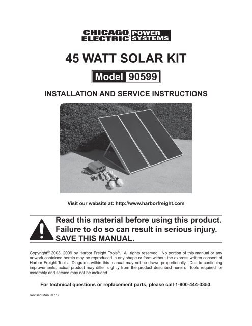
<strong>45</strong> <strong>WATT</strong> <strong>SOLAR</strong> <strong>KIT</strong><br />
Model 90599<br />
Installation and service Instructions<br />
Visit our website at: http://www.harborfreight.com<br />
Read this material before using this product.<br />
Failure to do so can result in serious injury.<br />
Save this manual.<br />
Copyright © 2003, 2009 by <strong>Harbor</strong> <strong>Freight</strong> <strong>Tools</strong> ® . All rights reserved. No portion of this manual or any<br />
artwork contained herein may be reproduced in any shape or form without the express written consent of<br />
<strong>Harbor</strong> <strong>Freight</strong> <strong>Tools</strong>. Diagrams within this manual may not be drawn proportionally. Due to continuing<br />
improvements, actual product may differ slightly from the product described herein. <strong>Tools</strong> required for<br />
assembly and service may not be included.<br />
For technical questions or replacement parts, please call 1-800-444-3353.<br />
Revised Manual 11k
Save This Manual<br />
Keep this manual for the safety<br />
warnings and precautions, installation,<br />
operating, inspection, maintenance and<br />
cleaning procedures. Write the product’s<br />
serial number in the back of the manual<br />
near the assembly diagram (or month<br />
and year of purchase if product has no<br />
number). Keep this manual and the<br />
receipt in a safe and dry place for future<br />
reference.<br />
Important SAFETY<br />
Information<br />
In this manual, on the labeling,<br />
and all other information<br />
provided with this product:<br />
This is the safety alert<br />
symbol. It is used to alert<br />
you to potential personal<br />
injury hazards. Obey all<br />
safety messages that<br />
follow this symbol to avoid<br />
possible injury or death.<br />
DANGER indicates<br />
a hazardous<br />
situation which, if not<br />
avoided, will result in death or<br />
serious injury.<br />
WARNING<br />
indicates a<br />
hazardous situation which, if<br />
not avoided, could result in<br />
death or serious injury.<br />
CAUTION, used<br />
with the safety<br />
alert symbol, indicates a<br />
hazardous situation which, if<br />
not avoided, could result in<br />
minor or moderate injury.<br />
NOTICE is used to<br />
address practices<br />
not related to personal injury.<br />
CAUTION, without<br />
the safety alert<br />
symbol, is used to address<br />
practices not related to<br />
personal injury.<br />
WARNING Read all safety<br />
warnings and instructions.<br />
Failure to follow the warnings and<br />
instructions may result in electric<br />
shock, fire and/or serious injury.<br />
Save all warnings and<br />
instructions for future reference.<br />
The warnings, precautions,<br />
and instructions discussed in<br />
this instruction manual cannot<br />
cover all possible conditions and<br />
situations that may occur. It must<br />
be understood by the operator that<br />
common sense and caution are<br />
factors which cannot be built into<br />
this product, but must be supplied<br />
by the operator.<br />
Installation Precautions<br />
1. Exercise special caution if working<br />
on roof or another high location.<br />
Keep proper footing and balance at<br />
all times. Follow ladder supplier’s<br />
precautions whenever working near<br />
or on a ladder.<br />
2. Install all sensitive electrical<br />
components (including wiring<br />
connections, regulator, and<br />
battery) inside a weatherproof<br />
enclosure to prevent electric<br />
shock.<br />
SKU 90599<br />
For technical questions, please call 1-800-444-3353.<br />
Page 2
3. Do not wire multiple panels in<br />
series. If you need to connect two<br />
or more solar panels together, this<br />
work must be done by a qualified<br />
electrician unless they are connected<br />
through a regulator.<br />
4. This solar panel kit is not designed<br />
for tie-in to a grid. Only a licensed<br />
electrician and a licensed building<br />
contractor can safely design and<br />
implement a grid tie-in system. Any<br />
grid tie-in system must meet all<br />
applicable building and electrical<br />
codes, and must meet standards<br />
established by the area power<br />
company. Improper grid tie-in can<br />
result in electrocution, fire, and other<br />
serious personal injury and property<br />
damage. An incorrectly installed grid<br />
tie-in system can cause feedback<br />
voltage, resulting in electrocution of<br />
electrical utility workers.<br />
5. Do not stand on or otherwise apply<br />
pressure to panel.<br />
6. Handle solar panel with care,<br />
edges may be sharp.<br />
7. Do not focus light on panel.<br />
8. Install components with enough<br />
space to allow proper cooling.<br />
9. This product may occasionally<br />
produce more current and/or<br />
voltage than its rated output.<br />
Increase output ratings by 25%<br />
when determining component<br />
required voltage and amperage<br />
ratings. Refer to Section 690-8 of<br />
the National Electrical Code for an<br />
additional multiplying factor of 125<br />
percent (80 percent derating) which<br />
may apply.<br />
10. Panel must be connected using<br />
UL listed outdoor rated wire of the<br />
correct thickness (gauge) for the<br />
amperage rating and length (see<br />
warning number 9 also). Follow the<br />
guidelines in the chart below:<br />
Current Maximum Length<br />
in Amps 5' 10' 15' 20' 25'<br />
0-5 18<br />
6-7 18 16<br />
8 18 16<br />
10<br />
16<br />
11-12 18<br />
16 14<br />
15<br />
18<br />
14 12<br />
20 18 16 14 12<br />
22-24 12<br />
10<br />
30<br />
14 10<br />
16<br />
40<br />
12 10 8<br />
50 14<br />
100 12 10 6 4<br />
150 10 8<br />
200 8 6<br />
4 2<br />
Minimum Wire Gauge<br />
11. Install an appropriate charge<br />
controller/regulator to regulate output<br />
and prevent damage. Do not attach<br />
panel to battery or power grid without<br />
proper regulator, inverter, and/or<br />
charge controller.<br />
12. Install and use according to<br />
applicable National Electrical Code<br />
(NEC) standards.<br />
13. This panel is not rated for use as<br />
fire-resistant roofing. If installing on<br />
a roof, install only over a fire resistant<br />
roof covering rated for the application.<br />
14. Verify that installation surface has no<br />
hidden utility lines before drilling or<br />
driving screws.<br />
15. Install only according to these<br />
instructions. Improper installation<br />
can create hazards.<br />
SKU 90599<br />
For technical questions, please call 1-800-444-3353.<br />
Page 3
16. Wear ANSI-approved safety goggles<br />
and heavy-duty work gloves during<br />
installation. Do not wear jewelry or<br />
metal watches when working near<br />
solar panels, wiring or batteries.<br />
17. Handle panel with care. Glass<br />
may break or a sharp edge may be<br />
exposed during movement.<br />
18. Keep installation area clean and well<br />
lit.<br />
19. Install out of reach of children.<br />
20. Keep bystanders out of the area<br />
during installation.<br />
21. Do not install when tired or when<br />
under the influence of drugs or<br />
medication.<br />
22. Use in 12 VDC systems only.<br />
Battery Precautions<br />
23. Wear splash-resistant ANSIapproved<br />
safety goggles and<br />
electrically insulated gloves while<br />
working near batteries.<br />
24. Use an appropriate charge<br />
controller whenever connected to<br />
battery.<br />
25. Charge, store, and maintain batteries<br />
according to supplier’s instructions.<br />
Service Precautions<br />
1. Before service, maintenance, or<br />
cleaning:<br />
a. Dry solar panels and outdoor<br />
wiring thoroughly while wearing<br />
electrically insulated gloves.<br />
b. Cover all solar panels with an<br />
opaque cover, such as a blanket.<br />
c. Disconnect all solar panels.<br />
d. Disconnect all batteries.<br />
2. Do not service during rain, fog, or<br />
any other wet/humid weather.<br />
3. Do not stand on or otherwise apply<br />
pressure to panel.<br />
4. Do not allow children to play with<br />
or near this item or electrical<br />
components.<br />
5. Inspect at least monthly; do not use<br />
if damaged, parts are loose, water is<br />
found inside the housing, electrical<br />
insulation is cracked or damaged, or<br />
connections are loose.<br />
6. Maintain product labels and<br />
nameplates. These carry important<br />
safety information. If unreadable or<br />
missing, contact <strong>Harbor</strong> <strong>Freight</strong> <strong>Tools</strong><br />
for a replacement.<br />
7. WARNING: Handling the cord on<br />
this product will expose you to lead,<br />
a chemical known to the State of<br />
California to cause cancer, and<br />
birth defects or other reproductive<br />
harm. Wash hands after handling.<br />
(California Health & Safety Code §<br />
25249.5, et seq.)<br />
Save these<br />
instructions.<br />
SKU 90599<br />
For technical questions, please call 1-800-444-3353.<br />
Page 4
Rated Output<br />
Specifications<br />
Open Circuit Voltage<br />
Adapter Outlets<br />
14.5 V~ / 15 W<br />
(working)<br />
23.5 OCV<br />
3, 6, 9 and 12 VDC<br />
Note: Output will decrease as the panel<br />
gets hotter than room temperature<br />
(~70° F). Angle, solar intensity,<br />
cloud cover and other factors will<br />
effect output<br />
Unpacking<br />
When unpacking, make sure that the<br />
item is intact and undamaged. If any parts<br />
are missing or broken, please call <strong>Harbor</strong><br />
<strong>Freight</strong> <strong>Tools</strong> at 1-800-444-3353 as soon<br />
as possible.<br />
to children to prevent electric shock.<br />
Build a childproof enclosure if<br />
needed.<br />
3. Install the charge controller/regulator<br />
and batteries in a weatherproof<br />
enclosure with proper ventilation.<br />
Mounting<br />
1. Angle the face of the panel toward<br />
true south 1 according to the chart that<br />
follows:<br />
Latitude Solar Panel Angle<br />
0-4° 10°<br />
5-20° Latitude + 5°<br />
21-<strong>45</strong>° Latitude + 10°<br />
46-64° Latitude + 15°<br />
65° or more 80°<br />
Assembly<br />
6a<br />
SKU 90599<br />
Installation<br />
Read the entire Important<br />
Safety Information<br />
section at the beginning of this<br />
manual including all text under<br />
subheadings therein before set<br />
up or use of this product.<br />
Note: For additional information regarding<br />
the parts listed in the following pages,<br />
refer to the Assembly Diagram near<br />
the end of this manual.<br />
Location<br />
1. Locate the panel where it will receive<br />
full, unobstructed sunlight, especially<br />
during midday. Nearby trees or tall<br />
plants will drop debris, requiring the<br />
panel to be cleaned more frequently.<br />
2. The installation location for the<br />
panels, charge controller/regulator,<br />
and batteries must be inaccessible<br />
For technical questions, please call 1-800-444-3353.<br />
1.<br />
6b<br />
Slot 3<br />
Slide the Left and Right Triangle<br />
Frame (6a and 6b) into slot 1 and<br />
slot 3 on both ends of the Top Link<br />
Bar (6d) and Bottom Link Bar (6C)<br />
(to form the frame assembly). See<br />
above.<br />
1<br />
Angle towards true north if installed in<br />
southern hemisphere.<br />
Page 5
6c<br />
6d<br />
Slot 2<br />
Slot 1<br />
provide enough ventilation to allow<br />
the unit to vent and cool properly.<br />
4. Secure the Frame Assembly (6a-<br />
6d) to its mounting location using<br />
hardware (not supplied) through the<br />
four holes on the bottom of the Left<br />
and Right Triangle Frames (6a &<br />
6b).<br />
2.<br />
Push the Top Link Bar (6d) down to<br />
slot 2 (to lock the frame assembly).<br />
See above.<br />
3. Determine where you want to position<br />
the Frame Assembly (6a-6d) making<br />
sure it is facing south (for maximum<br />
sun exposure) with no obstructions<br />
in front of it. The Regulator (2) must<br />
be in a dry, well ventilated location<br />
nearby. If necessary, build a small<br />
structure that guarantees the unit will<br />
stay dry during rain or snow, and,<br />
5. Carefully place each Solar Panel (1)<br />
on the front of the Frame Assembly<br />
(6a-6d) so that the bottom of each<br />
panel fits into the slot on the bottom<br />
of the Frame Assembly (6a-6d).<br />
6. Lock the two eye hooks on the backcenter<br />
frame into the two protruding<br />
bolts on the Top Link Bar (6d).<br />
CAUTION: If the unit is to be mounted<br />
on a rooftop, be especially careful<br />
when climbing ladders and walking<br />
on sloped roofs. Additional hardware<br />
may have to be purchased if<br />
SKU 90599<br />
For technical questions, please call 1-800-444-3353.<br />
Page 6
7.<br />
lead<br />
wires<br />
permanently mounting the Solar<br />
panels on a rooftop.<br />
Hook-Up Diagram<br />
Solar Panels (1)<br />
Regulator (2)<br />
Connect the two ring connectors at<br />
the end of the lead wires coming<br />
from the Solar Panels (1) to the<br />
Solar Terminals on the Regulator<br />
(2). See FIGURE 1. Be sure to<br />
connect by matching polarities on<br />
the wires and the Regulator (2).<br />
Black (-) is negative and red (+) is<br />
positive. Then, connect the wire<br />
leads so that all of the Solar Panels<br />
(1) are connected to each other and<br />
the Regulator (2) (again, making<br />
sure you are hooking up to the right<br />
polarity on the Regulator). See<br />
Hook-Up Diagram, above.<br />
Wiring<br />
Note: Only a licensed electrician and<br />
a licensed building contractor can<br />
safely design and implement a grid<br />
tie-in system. Any grid tie-in system<br />
must meet all applicable building<br />
and electrical codes, and must meet<br />
standards established by the area<br />
power company.<br />
1. Run wires from the panels, through<br />
weatherproof grommets and into<br />
the enclosure where the charge<br />
controller/regulator is located. Use<br />
wires of the proper size and rating.<br />
2. Connect to charge controller/regulator<br />
according to controller/regulator’s<br />
instructions.<br />
3. Secure all connections using<br />
terminals, or solder all wire splices to<br />
ensure good connections.<br />
4. Weatherproof all connections.<br />
Operation<br />
Note: Performance of the Solar Panels<br />
will vary dependent on site location,<br />
angle of the panels in relation to the<br />
arc of the sun, and available sunlight.<br />
Recharging a Battery<br />
1. To recharge a 12 volt battery (not<br />
included), while paying attention<br />
to the proper polarity (black (-) is<br />
negative and red (+) is positive),<br />
connect the two ring terminals on<br />
the Battery Connector (3) to the<br />
Battery Terminals on the back of<br />
the Regulator (2). See FIGURE<br />
1. Then, connect the black clamp to<br />
the black or negative (-) terminal on<br />
the battery (not included). Finally,<br />
connect the red clamp to the red or<br />
positive (+) terminal on the battery.<br />
Avoid accidental contact of the red<br />
and black battery clamps to each<br />
other.<br />
Note: Do not change the order explained<br />
in number 1 above or electric shock<br />
resulting in serious injury or death<br />
may occur.<br />
2. Turn on the Regulator. See the On/<br />
Off switch in FIGURE 1 on page 6.<br />
3. Never leave the battery (not included)<br />
unattended while charging. When<br />
the battery (not included) is fully<br />
charged, the reading on the voltage<br />
display will show “13” or above.<br />
Note: the voltage display will have to<br />
be turned on in order to monitor the<br />
SKU 90599<br />
For technical questions, please call 1-800-444-3353.<br />
Page 7
atter voltage. (It is recommended to<br />
leave the voltage display off when not<br />
monitoring the battery voltage since it<br />
consumes energy.) Twelve (12) Volt<br />
batteries should charge to 13 Volts<br />
for a full charge. If the intent is to<br />
stop charging the battery, disconnect<br />
the solar panels from the charge<br />
regulator. Note: The charge regulator<br />
provides “over charge” protection. If<br />
the battery voltage is higher than 14.5<br />
V, the regulator will shut off charge<br />
from solar panel.<br />
4. The Regulator (2) provides the<br />
following protection while charging:<br />
a. Over-discharge Protection: When<br />
the electricity level of the battery<br />
(not included) goes too low (below<br />
11 volts) the Regulator (2) will<br />
automatically shut off the power<br />
output to prevent damage to the<br />
battery (not included). If this occurs,<br />
stop using the battery (not included)<br />
and charge it until the Voltage<br />
display shows 13 volts.<br />
b. Overcharge Protection: If the<br />
electricity level on the battery (not<br />
included) goes too high (above<br />
14.5 volts) the Regulator (2) will<br />
automatically shut off power input to<br />
prevent damage to the battery (not<br />
included).<br />
c. Overload Protection: If the output<br />
current exceeds 4 amps the fuse<br />
(See FIGURE 1) will blow to prevent<br />
damage to the controller in the<br />
Regulator (2). If this occurs, have a<br />
qualified service technician replace<br />
the fuse.<br />
Note: The On/Off switch of the charge<br />
regulator must be in the “On”<br />
position to activate the three<br />
protection functions mentioned<br />
above.<br />
SKU 90599<br />
Using the 12 Volt Lights and<br />
Accessories.<br />
Note: The Charge Regulator must be in<br />
“ON” position at all times.<br />
1. If the 12 Volt Lights (4) aren’t<br />
already attached to the sockets on<br />
the end of each Light Wire (7), gently<br />
snap them in.<br />
2. Plug the other end of the Light<br />
Wire (7) into any one of the 12 Volt<br />
DC outlets on the Regulator (2) as<br />
shown in FIGURE 2.<br />
12 Volt DC<br />
Socket<br />
Figure 2<br />
Voltage<br />
Display<br />
3. To turn off the lights, unplug the Light<br />
Wire (7) from the 12 Volt DC outlet<br />
on the Regulator (2). You may plug<br />
in the other 12 Volt Light (4) to either<br />
12 Volt DC outlet.<br />
Note: This system can also be used to<br />
power other small 3 Volt DC, 6 Volt<br />
DC, and 9 Volt DC small appliances.<br />
For technical questions, please call 1-800-444-3353.<br />
Led<br />
Display<br />
Switch<br />
Controller<br />
Power<br />
Switch<br />
Light Sockets<br />
Page 8<br />
REV 10k
4. Plug the appropriate plug on the<br />
Multi Purpose Adapter (5) into the<br />
appliance. The adapter has 3 Volt<br />
DC, 5 Volt DC, 6 Volt DC, 9 Volt DC,<br />
and 12 Volt DC plugs.<br />
5. Insert the plug on the other end of the<br />
wire attached to the Multi Purpose<br />
Adapter (5) into the appropriate DC<br />
Outlet on the Regulator (2). For<br />
your reference, FIGURE 2 shows the<br />
adapter wire plugged into the 3 Volt<br />
DC outlet.<br />
6. Operate your appliance.<br />
7. When finished, unplug the Multi<br />
Purpose Adapter (5) wire plug from<br />
the Regulator (2) and then unplug<br />
the Multi Purpose Adapter (5) from<br />
the appliance.<br />
Servicing<br />
Procedures not specifically<br />
explained in this manual<br />
must be performed only by a<br />
qualified technician.<br />
To prevent<br />
serious injury<br />
from Electric Shock:<br />
Before service, maintenance,<br />
or cleaning:<br />
a. Dry solar panels and outdoor<br />
wiring thoroughly while<br />
wearing electrically insulated<br />
gloves.<br />
b. Cover all solar panels with<br />
an opaque cover, such as a<br />
blanket.<br />
c. Disconnect all solar panels.<br />
d. Disconnect all batteries.<br />
To prevent serious<br />
injury from electric<br />
shock or cuts:<br />
Do not use damaged solar<br />
panel. If wiring insulation<br />
is damaged or weathered,<br />
glass is cracked, or housing<br />
is opened, have the problem<br />
corrected before further use.<br />
Note: It is normal to see up to 20%<br />
degradation in amorphous silicon<br />
solar panel performance within the<br />
first 6 months before the amorphous<br />
coating stabilizes.<br />
Cleaning<br />
Clean and inspect the solar panel<br />
system MONTHLY, or more<br />
frequently to maintain peak efficiency:<br />
1. Wear electrically insulated gloves<br />
and ANSI-approved safety goggles.<br />
Dry solar panels and outdoor wiring<br />
thoroughly.<br />
2. Cover all solar panels with an<br />
opaque cover, such as a blanket.<br />
3. Disconnect all solar panels and<br />
batteries.<br />
4. Clean solar panels one at a time with<br />
mild, non-abrasive cleanser and soft<br />
cloth and paper towels. Do not clean<br />
with brushes or abrasive cleaners.<br />
5. Inspect the general condition of the<br />
solar panel system (panels, batteries,<br />
controllers, and mounting). Check<br />
for loose hardware, wiring insulation<br />
damage or weathering, cracked<br />
glass, open housing, cracked or<br />
broken parts, loose or corroded<br />
contacts, and any other condition that<br />
may affect its safe operation.<br />
SKU 90599<br />
For technical questions, please call 1-800-444-3353.<br />
Page 9
6. Inspect and maintain batteries<br />
according to supplier’s instructions.<br />
Adjustment<br />
To Increase Efficiency:<br />
7. In the Winter, increase the panel’s<br />
angle by 10°.<br />
8. In the Summer, decrease the angle<br />
by up to 10°.<br />
9. In the Spring and Fall, keep the<br />
panel at the angle recommended on<br />
the chart on page 9.<br />
SKU 90599<br />
For technical questions, please call 1-800-444-3353.<br />
Page 10
PLEASE READ THE FOLLOWING CAREFULLY<br />
The manufacturer and/or distributor has provided the parts list and assembly<br />
diagram in this manual as a reference tool only. Neither the manufacturer or<br />
distributor makes any representation or warranty of any kind to the buyer that<br />
he or she is qualified to make any repairs to the product, or that he or she is<br />
qualified to replace any parts of the product. In fact, the manufacturer and/<br />
or distributor expressly states that all repairs and parts replacements should<br />
be undertaken by certified and licensed technicians, and not by the buyer. The<br />
buyer assumes all risk and liability arising out of his or her repairs to the<br />
original product or replacement parts thereto, or arising out of his or her<br />
installation of replacement parts thereto.<br />
Parts List and Assembly Diagram<br />
Part Description Q’ty<br />
1 Solar Panel 3<br />
2 Regulator 1<br />
3 Battery Connector 1<br />
4 12 Volt Light 2<br />
5 Multi-purpose Adapter 1<br />
Part Description Q’ty<br />
6a Left Triangle Frame 1<br />
6b Right Triangle Frame 1<br />
6c Bottom Link Bar 1<br />
6d Top Link Bar 1<br />
7 Light Wire 2<br />
2<br />
7<br />
Record Product’s Serial Number Here:<br />
Note: If product has no serial number, record month and year of purchase instead.<br />
Note: Some parts are listed and shown for illustration purposes only, and are not<br />
available individually as replacement parts.<br />
SKU 90599<br />
5<br />
For technical questions, please call 1-800-444-3353.<br />
4<br />
REV 11k<br />
Page 11