Manual tire changer - Harbor Freight Tools
Manual tire changer - Harbor Freight Tools
Manual tire changer - Harbor Freight Tools

You also want an ePaper? Increase the reach of your titles
YUMPU automatically turns print PDFs into web optimized ePapers that Google loves.
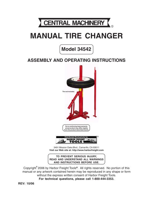
MANUAL TIRE CHANGER<br />
Model 34542<br />
ASSEMBLY AND OPERATING INSTRUCTIONS<br />
Tire not included.<br />
Do to continuing improvements,<br />
actual product may differ slighlty<br />
from the product described herein.<br />
®<br />
©<br />
3491 Mission Oaks Blvd., Camarillo, CA 93011<br />
Visit our Web site at: http://www.harborfreight.com<br />
TO PREVENT SERIOUS INJURY,<br />
READ AND UNDERSTAND ALL WARNINGS<br />
AND INSTRUCTIONS BEFORE USE.<br />
Copyright 2006 by <strong>Harbor</strong> <strong>Freight</strong> <strong>Tools</strong> ® . All rights reserved. No portion of this<br />
manual or any artwork contained herein may be reproduced in any shape or form<br />
without the express written consent of <strong>Harbor</strong> <strong>Freight</strong> <strong>Tools</strong>.<br />
For technical questions, please call 1-800-444-3353.<br />
REV: 10/06
PRODUCT SPECIFICATIONS<br />
Item<br />
Description<br />
Product Applications<br />
Will handle all <strong>tire</strong>s from 8” to light trucks<br />
such as 7.5” x 16” and flotation <strong>tire</strong>s up<br />
to sizes 12.5”L x 16”.<br />
Base Dimensions 15” x 18”<br />
Base Mounting Holes 7/16” Diameter (Qty. 4)<br />
Mounting/Dismounting Bar 37” Long x 1-15/16” Diameter<br />
Dimensions<br />
Wheel Rest Plate Dimensions 7-1/2” Diameter x 3/16” Thick<br />
Leg Dimensions<br />
1-1/2” x 3” x .15 (Wall Channel)<br />
Main Column Dimensions 2-7/8” Diameter<br />
Construction<br />
All Steel<br />
Additional Features<br />
No Air or Electrical Connections Required.<br />
Designed to Protect Tube From Damage.<br />
Approximate Weight<br />
42 Pounds<br />
SAVE THIS MANUAL<br />
You will need this manual for the safety warnings and precautions, assembly, operating,<br />
inspection, maintenance and cleaning procedures, parts list and assembly diagram.<br />
Keep your invoice with this manual. Write the invoice number on the inside of the front<br />
cover. Keep this manual and invoice in a safe and dry place for future reference.<br />
GENERAL SAFETY RULES AND PRECAUTIONS<br />
WARNING!<br />
READ AND UNDERSTAND ALL INSTRUCTIONS<br />
Failure to follow all instructions listed below may result in<br />
serious injury.<br />
SAVE THESE INSTRUCTIONS<br />
WORK AREA<br />
1. Keep your work area clean and well lit. Cluttered benches and dark areas<br />
invite accidents.<br />
2. Do not operate tools and equipment in explosive atmospheres, such<br />
as in the presence of flammable liquids, gases, or dust. <strong>Tools</strong> and<br />
equipment can create sparks which may ignite the dust or fumes.<br />
SKU 34542 For technical questions, please call 1-800-444-3353 PAGE 2
3. Keep bystanders, children, and visitors away while operating tools and<br />
equipment. Distractions can cause you to lose control. Provide barriers or<br />
shields as needed.<br />
PERSONAL SAFETY<br />
1. Stay alert. Watch what you are doing, and use common sense when operating<br />
tools and equipment. Do not use a tool or equipment while <strong>tire</strong>d or<br />
under the influence of drugs, alcohol, or medication. A moment of inattention<br />
while operating tools and equipment may result in serious personal injury.<br />
2. Dress properly. Do not wear loose clothing or jewelry. Contain long hair.<br />
Keep your hair, clothing, and gloves away from moving parts. Loose<br />
clothes, jewelry, or long hair can be caught in moving parts.<br />
3. Do not overreach. Keep proper footing and balance at all times. Proper<br />
footing and balance enables better control of the power tool in unexpected<br />
situations.<br />
4. Use safety equipment. Always wear eye protection. Always wear<br />
ANSI-approved safety impact goggles and a full face shield when using<br />
and/or installing this product.<br />
TOOL USE AND CARE<br />
1. Do not force the tool. Use the correct tool for your application. The correct<br />
tool will do the job better and safer at the rate for which it is designed.<br />
2. Store idle tools out of reach of children and other untrained persons. <strong>Tools</strong><br />
are dangerous in the hands of untrained users.<br />
3. Maintain tools with care. Properly maintained tools are less likely to malfunction<br />
and are easier to control. Do not use a damaged tool. Tag damaged tools<br />
“Do Not Use” until repaired.<br />
4. Check for misalignment or binding of moving parts, breakage of parts, and<br />
any other condition that may affect the tool’s operation. If damaged, have<br />
the tool serviced before using. Many accidents are caused by poorly maintained<br />
tools.<br />
5. Use only accessories that are recommended by the manufacturer for your<br />
model. Accessories that may be suitable for one tool may become hazardous<br />
when used on another tool.<br />
SKU 34542 For technical questions, please call 1-800-444-3353 PAGE 3
SERVICE<br />
1. Tool service must be performed only by qualified repair personnel. Service<br />
or maintenance performed by unqualified personnel could result in a risk of injury.<br />
2. When servicing a tool, use only identical replacement parts. Follow<br />
instructions in the “Inspection, Maintenance, And Cleaning” section of this<br />
manual. Use of unauthorized parts or failure to follow maintenance instructions<br />
may create a risk of electric shock or injury.<br />
SPECIFIC SAFETY RULES AND PRECAUTIONS<br />
1. Maintain labels and nameplates on the Tire Changer. These carry important<br />
information. If unreadable or missing, contact <strong>Harbor</strong> <strong>Freight</strong> <strong>Tools</strong> for a<br />
replacement.<br />
2. Make sure the Tire Changer is located on a flat, level, sturdy surface capable<br />
of supporting the weight of the Tire Changer, <strong>tire</strong>s, and any additional<br />
tools and equipment.<br />
3. Industrial applications must follow OSHA guidelines.<br />
4. Never stand on the Tire Changer. Serious injury could result if the Tire<br />
Changer is tipped.<br />
5. Do not allow children and other unauthorized people to handle or play with<br />
the Tire Changer.<br />
6. Do not force the Tire Changer. This tool will do the work better and safer at<br />
the speed and capacity for which it was designed.<br />
7. Prior to using the Tire Changer, always read and follow the instructions and<br />
safety precautions as outlined in the <strong>tire</strong> manufacturer and vehicle<br />
manufacturer’s owners manuals.<br />
8. Never leave a vehicle running when changing/repairing <strong>tire</strong>s. When<br />
running an Engine in an enclosed area, the Engine produces carbon<br />
monoxide, a colorless, odorless, toxic gas that, when inhaled, can<br />
cause serious personal injury or death. Whenever possible, use a<br />
carbon monoxide detector (not included) to detect excessive carbon<br />
monoxide fumes in the work area and in the surrounding area.<br />
9. Do not use this product if under the influence of alcohol or drugs. Read<br />
warning labels on prescriptions to determine if your judgement or reflexes are<br />
SKU 34542 For technical questions, please call 1-800-444-3353 PAGE 4
impaired while taking drugs. If there is any doubt, do not attempt to use this<br />
product.<br />
10. Use the right tool for the job. Do not attempt to force a small tool to do the<br />
work of a larger industrial tool. There are certain applications for which this<br />
product was designed. It will do the job better and more safely at the rate for<br />
which it was intended. Do not modify this product, and do not use this product<br />
for a purpose for which it was not intended.<br />
11. EXPLOSION DANGER! Never overinflate <strong>tire</strong>s or other inflatable items.<br />
When inflating a <strong>tire</strong> with compressed air, make sure to inflate the <strong>tire</strong> to<br />
the exact PSI as recommended by the <strong>tire</strong> manufacturer. Always use a<br />
pressure gauge (not included) to check the actual pressure in <strong>tire</strong>s.<br />
12. Always dispose of old <strong>tire</strong>s in accordance with local, state, and federal<br />
laws.<br />
13. WARNING! The warnings and precautions discussed in this manual cannot<br />
cover all possible conditions and situations that may occur. It must be under<br />
stood by the operator that common sense and caution are factors which cannot<br />
be built into this product, but must be supplied by the operator.<br />
SAVE THESE INSTRUCTIONS<br />
UNPACKING<br />
When unpacking, check to make sure all the parts shown on the Parts Lists on page 10<br />
are included. If any parts are missing or broken, please call <strong>Harbor</strong> <strong>Freight</strong> <strong>Tools</strong> at the<br />
number shown on the cover of this manual as soon as possible.<br />
ASSEMBLY INSTRUCTIONS<br />
1. Locate the Hex Bolts (6), Lock Washers (11), Hex Head Nuts (12), Center Post<br />
(1), and the Pedestal Base (13). (See Assy. Diagram.)<br />
2. Bolt the Pedestal Base (13) to the Center Post (1), using the Hex Bolts (6), Lock<br />
Washers (11), and Hex Head Nuts (12). NOTE: The end of the Pedestal Base<br />
with the triangular stop should be directly in front of the Bead Breaker Handle (7)<br />
and Bead Breaker Shoe (10). (See Assy. Diagram.)<br />
3. Bolt the two Side Base Channels (9) into place. (See Assy. Diagram.)<br />
SKU 34542 For technical questions, please call 1-800-444-3353 PAGE 5
SECURING THE TIRE CHANGER TO A FLOOR SURFACE<br />
1. Choose a concrete floor surface location for the Tire Changer that is well lighted,<br />
offers adequate workspace, and is away from high pedestrian traffic areas.<br />
2. The concrete floor surface should be at least 4” in depth. (See Figure A.)<br />
3. With assistance, move the Tire Changer to the location. Use the Tire Changer’s<br />
four 7/16” mounting holes at its base as a template for which four 7/16” holes will<br />
be drilled in the concrete surface. Do not use a concrete drill bit larger in<br />
diameter than 7/16”. (See Figure A.)<br />
4. Temporarily set the Tire Changer aside. Then drill four holes in the concrete floor<br />
surface equal to the length of four 7/16” diameter cement anchors (not included)<br />
you will use to secure the Tire Changer to the floor surface. (See Figure A.)<br />
5. Once the four 7/16” diameter holes are drilled, blow out the concrete dust from<br />
each of the holes. (See Figure A.)<br />
6. Set the Tire Changer back on the concrete floor surface, and align its four<br />
mounting holes at its base with the four pre-drilled holes in the floor surface.<br />
7. If necessary, level the Tire Changer on the concrete floor surface using a<br />
carpenter’s level and steel shims (neither included).<br />
8. Use a hammer (not included) to tap the four cement anchors through the four<br />
mounting holes in the base of the Tire Changer and into the concrete floor surface.<br />
Continue tapping the cement anchors until their washer rests against the<br />
base of the Tire Changer. (See Figure A.)<br />
9. Firmly tighten the nuts of the four cement anchors to secure the Tire Changer to<br />
the concrete floor surface. (See Figure A.)<br />
DRILL HOLES<br />
TO DEPTH EQUAL<br />
TO LENGTH OF<br />
CEMENT ANCHOR.<br />
INSERT<br />
CEMENT ANCHOR<br />
SO THAT WASHER<br />
RESTS AGAINST<br />
BASE OF<br />
TIRE CHANGER.<br />
FIRMLY<br />
TIGHTEN<br />
CEMENT<br />
ANCHOR<br />
NUT.<br />
FIGURE A<br />
SKU 34542 For technical questions, please call 1-800-444-3353 PAGE 6
OPERATING INSTRUCTIONS<br />
Bead Breaking:<br />
1. Before starting, use a rubber lubricant (not included) to help make bead breaking,<br />
mounting, and demounting easier.<br />
2. Deflate the <strong>tire</strong> completely.<br />
3. To break the bead from the rim of the <strong>tire</strong>, lay the <strong>tire</strong> flat on the Pedestal Base<br />
(13). The triangular stop is used to keep the <strong>tire</strong> from sliding.<br />
4. Insert the flat end of the Mount/Demount Bar (14) into the Bead Breaker Handle<br />
(7).<br />
5. Set the Bead Breaker Shoe (10) on the <strong>tire</strong> against the edge of the rim. As you<br />
work, you may need to adjust the Bead Breaker Shoe height by removing the<br />
Clevis Pegs (5) and moving the Shoe to the appropriate height. Then, reinsert<br />
the Clevis Pegs.<br />
6. Push down on the Mount/Demount Bar (14) to force the bead off the rim. If the<br />
bead does not come off all at once, turn the <strong>tire</strong> and try again in several locations.<br />
7. Turn the <strong>tire</strong> over, and repeat Steps #1 through #6 above.<br />
Demounting And Mounting Tires:<br />
1. After the bead is broken, place the <strong>tire</strong> up on the machine with the valve stem<br />
facing up and the Wheel Lug Peg (3) sticking up through the lug hole of the rim.<br />
2. Place the Spider Pedestal (4) over the Center Post (1) with the tapered side<br />
going into the wheel hub.<br />
3. Screw the Pedestal Cap (2) onto the Center Post (1). Lock the Spider Pedestal<br />
(4) into place by tightening snugly by hand. Hand tightening should be adequate.<br />
However, if you want more pressure place the flat end of the Mount/Demount<br />
Bar (14) through the top of the Pedestal Cap and use extra leverage to tighten<br />
the Pedestal Cap further.<br />
4. Once the <strong>tire</strong> is held securely in place, force the flat end of the Mount/Demount<br />
Bar (14) in between the <strong>tire</strong> and the rim. This should be done with the flat end of<br />
the Mount/Demount Bar against the rim. Pull the Mount/Demount Bar toward<br />
you and across the <strong>tire</strong> to force the edge of the bead over the rim.<br />
SKU 34542 For technical questions, please call 1-800-444-3353 PAGE 7
5. Work the Mount/Demount Bar (14) all the way around the Center Post (1) to<br />
demount the bead completely.<br />
6. Pull the <strong>tire</strong> up toward the top of the bead. Place the flat end of the<br />
Mount/Demount Bar (14) between the <strong>tire</strong> and the rim as before. Then, repeat<br />
the process to remove the <strong>tire</strong> from the rim completely.<br />
7. Repair the <strong>tire</strong>. Then, mount the <strong>tire</strong> back on the rim and set the <strong>tire</strong> on top of<br />
the rim.<br />
8. Hook the end of the Mount/Demount Bar (14) over the edge of the rim.<br />
9. Push the <strong>tire</strong> forward over the edge of the rim at the place the Mount/Demount<br />
Bar (14) is.<br />
10. Position the bead so it will slide across the flat portion of the hook end of the<br />
Mount/Demount Bar (14).<br />
11. Press down on the <strong>tire</strong> with one hand against the rim. With the other hand, pull<br />
the Mount/Demount Bar (14) clockwise around the Center Post (1) until the bead<br />
starts to mount on the rim. It should only have to move a few inches before you<br />
can let go of the <strong>tire</strong> and use both hands on the Mount/Demount Bar.<br />
12. Continue around the rim until the <strong>tire</strong> mounts over the edge of the bead. Repeat<br />
this procedure on the second bead to completely mount the <strong>tire</strong>.<br />
13. IMPORTANT: If the <strong>tire</strong> bead starts to seat while you are mounting the <strong>tire</strong>, the<br />
<strong>tire</strong> will need to stretch more and will be more difficult to mount. To prevent this,<br />
push down on the <strong>tire</strong> so it doesn’t seat on the upper edge of the rim during<br />
mounting.<br />
14. NOTE: The bead running across the top of the Mount/Demount Bar (14) keeps<br />
the Bar hooked on the edge of the rim. The <strong>tire</strong> bead will run across the top (flat<br />
part of the mounting end of the Bar) and against the curved Wheel Lug Peg (3)<br />
when mounting the <strong>tire</strong> on the rim.<br />
ATV Tires:<br />
1. NOTE: ATV <strong>tire</strong>s are difficult to demount and mount because of their small<br />
diameter. Additionally, the <strong>tire</strong>s are soft and bend easily when breaking the bead.<br />
2. If the Bead Breaker Shoe (10) slides off the <strong>tire</strong>, hold the Shoe in place and work<br />
around the rim breaking the bead a little at a time.<br />
3. Place lubricant between the <strong>tire</strong> and rim to make it slide off easier.<br />
SKU 34542 For technical questions, please call 1-800-444-3353 PAGE 8
4. If the wheel has a tall rim with a small inside diameter so that the rim does not go<br />
over the round plate on the Center Post (1) and will not accept the Spider Pedestal<br />
(4), or let the Wheel Lug Peg (3) through its hole, you should still be able to<br />
use this Tire Changer to demount and mount the <strong>tire</strong>. Most rims are held in<br />
place adequately by tightening the Center Post Cap down snugly. With the Cap<br />
in place, you should still be able to hold the rim in place to mount and demount<br />
the <strong>tire</strong> as discussed previously.<br />
INSPECTION, MAINTENANCE, AND CLEANING<br />
1. Before each use, inspect the general condition of the Tire Changer. Check for<br />
loose screws, misalignment or binding of moving parts, cracked or broken parts,<br />
and any other condition that may affect the safe operation of the Tire Changer. If<br />
abnormal noise or vibration occurs, have the problem corrected before further<br />
use. Do not use damaged equipment.<br />
2. To clean the Tire Changer, use a mild detergent or mild solvent. Then, dry.<br />
3. CAUTION! All maintenance, service, or repairs not mentioned in this<br />
manual must only be performed by a qualified service technician.<br />
PLEASE READ THE FOLLOWING CAREFULLY<br />
THE MANUFACTURER AND/OR DISTRIBUTOR HAS PROVIDED THE PARTS LIST<br />
AND ASSEMBLY DIAGRAM IN THIS MANUAL AS A REFERENCE TOOL ONLY. NEI-<br />
THER THE MANUFACTURER OR DISTRIBUTOR MAKES ANY REPRESENTATION OR<br />
WARRANTY OF ANY KIND TO THE BUYER THAT HE OR SHE IS QUALIFIED TO<br />
REPLACE ANY PARTS OF THE PRODUCT. IN FACT, THE MANUFACTURER AND/OR<br />
DISTRIBUTOR EXPRESSLY STATES THAT ALL REPAIRS AND PARTS REPLACE-<br />
MENTS SHOULD BE UNDERTAKEN BY CERTIFIED AND LICENSED TECHNICIANS,<br />
AND NOT BY THE BUYER. THE BUYER ASSUMES ALL RISKS AND LIABILITY ARIS-<br />
ING OUT OF HIS OR HER REPAIRS TO THE ORIGINAL PRODUCT OR REPLACE-<br />
MENT PARTS THERETO, OR ARISING OUT OF HIS OR HER INSTALLATION OF<br />
REPLACEMENT PARTS THERETO.<br />
SKU 34542 For technical questions, please call 1-800-444-3353 PAGE 9
PARTS LIST AND ASSEMBLY DIAGRAM<br />
Part # Description Qty. Part # Description Qty.<br />
1 Center Post 1 8 Hump Pin & Rings 2<br />
2 Pedestal Cap 1 9 Side Base Channel 2<br />
3 Wheel Lug Peg 1 10 Bead Breaker Shoe 1<br />
4 Spider Pedestal 1 11 Lock Washer (3/8”) 4<br />
5 Clevis Pegs (7/16”) 2 12 Hex Head Nut (3/8” x 16) 4<br />
6 Large Hex Bolt (3/8” x 16 x 1”) 4 13 Pedestal Base 1<br />
7 Bead Breaker Handle 1 14 Mount/Demount Bar 1<br />
2<br />
4<br />
3<br />
5<br />
7<br />
1<br />
5<br />
6 6<br />
6<br />
14<br />
6<br />
13<br />
8<br />
8<br />
9<br />
10<br />
11<br />
11<br />
9<br />
12<br />
11<br />
12<br />
11<br />
12<br />
12<br />
NOTE:<br />
Some parts are listed and shown for illustration purposes only,<br />
and are not available individually as replacement parts.<br />
SKU 34542 For technical questions, please call 1-800-444-3353 PAGE 10
WARRANTY<br />
LIMITED 90 DAY WARRANTY<br />
<strong>Harbor</strong> <strong>Freight</strong> <strong>Tools</strong> Co. makes every effort to assure that its products meet high quality and durability standards,<br />
and warrants to the original purchaser that this product is free from defects in materials and workmanship for<br />
the period of ninety days from the date of purchase. This warranty does not apply to damage due directly or<br />
indirectly, to misuse, abuse, negligence or accidents, repairs or alterations outside our facilities, or to lack of<br />
maintenance. We shall in no event be liable for death, injuries to persons or property, or for incidental, contingent,<br />
special or consequential damages arising from the use of our product. Some states do not allow the exclusion or<br />
limitation of incidental or consequential damages, so the above limitation of exclusion may not apply to you. THIS<br />
WARRANTY IS EXPRESSLY IN LIEU OF ALL OTHER WARRANTIES, EXPRESS OR IMPLIED, INCLUDING<br />
THE WARRANTIES OF MERCHANTABILITY AND FITNESS.<br />
To take advantage of this warranty, the product or part must be returned to us with transportation charges prepaid.<br />
Proof of purchase date and an explanation of the complaint must accompany the merchandise. If our inspection<br />
verifies the defect, we will either repair or replace the product at our election or we may elect to refund the purchase<br />
price if we cannot readily and quickly provide you with a replacement. We will return repaired products at our<br />
expense, but if we determine there is no defect, or that the defect resulted from causes not within the scope of<br />
our warranty, then you must bear the cost of returning the product.<br />
This warranty gives you specific legal rights and you may also have other rights which vary from state to state.<br />
3491 Mission Oaks Blvd. • PO Box 6009 • Camarillo, CA 93011 • (800) 444-3353<br />
SKU 34542 For technical questions, please call 1-800-444-3353 PAGE 11