Lightweight and High-efficiency Drive Shafts for Rear-wheel ... - NTN
Lightweight and High-efficiency Drive Shafts for Rear-wheel ... - NTN
Lightweight and High-efficiency Drive Shafts for Rear-wheel ... - NTN

You also want an ePaper? Increase the reach of your titles
YUMPU automatically turns print PDFs into web optimized ePapers that Google loves.
<strong>NTN</strong> TECHNICAL REVIEW No.792011<br />
New Product <br />
<strong>Lightweight</strong> <strong>and</strong> <strong>High</strong>-<strong>efficiency</strong> <strong>Drive</strong> <strong>Shafts</strong><br />
<strong>for</strong> <strong>Rear</strong>-<strong>wheel</strong>-drive Cars<br />
Tatsuro SUGIYAMA<br />
Yuichi ASANO<br />
A lightweight <strong>and</strong> high-<strong>efficiency</strong> drive shaft designed<br />
exclusively <strong>for</strong> rear-<strong>wheel</strong>-drive cars with a mass reduction by<br />
16% <strong>and</strong> a torque loss rate reduced by 40% in comparison<br />
with conventional products.<br />
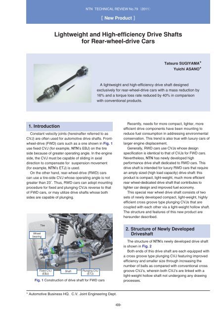
1. Introduction<br />
Constant velocity joints (hereinafter referred to as<br />
CVJ) are often used <strong>for</strong> automotive drive shafts. Front<strong>wheel</strong>-drive<br />
(FWD) cars such as a one shown in Fig. 1<br />
use fixed CVJ (<strong>for</strong> example, <strong>NTN</strong>’s EBJ) on the tire<br />
side because of greater operating angle. In the engine<br />
side, the CVJ must be capable of sliding in axial<br />
direction to compensate <strong>for</strong> suspension movement<br />
(<strong>for</strong> example, <strong>NTN</strong>’s ETJ) is used.<br />
On the other h<strong>and</strong>, rear-<strong>wheel</strong>-drive (RWD) cars<br />
can use a tire-side CVJ whose operating angle is not<br />
greater than 23˚. Thus, RWD cars can adopt mounting<br />
procedure <strong>for</strong> fixed <strong>and</strong> plunging CVJs reverse to that<br />
of FWD cars, or may utilize drive shafts whose both<br />
sides are capable of plunging.<br />
Wheel<br />
bearing<br />
Tire<br />
Fixed CVJ<br />
(EBJ)<br />
Shaft<br />
Plunging CVJ<br />
(ETJ)<br />
Fig. 1 Construction of drive shaft <strong>for</strong> FWD cars<br />
Recently, needs <strong>for</strong> more compact, lighter, more<br />
efficient drive components have been mounting to<br />
reduce fuel consumption in addressing environmental<br />
conservation. This trend is also true with luxury cars of<br />
larger engine displacement.<br />
Generally, RWD cars use CVJs whose design<br />
specification is identical to that of CVJs <strong>for</strong> FWD cars.<br />
Nevertheless, <strong>NTN</strong> has newly developed high<br />
per<strong>for</strong>mance drive shaft dedicated to RWD cars. This<br />
drive shaft is intended <strong>for</strong> luxury RWD cars that require<br />
an amply sized (high load capacity) drive shaft: this<br />
product is compact, light-weight, much more efficient<br />
rear <strong>wheel</strong>-dedicated drive shaft that contributes to<br />
lighter car design <strong>and</strong> improved fuel economy.<br />
This special rear <strong>wheel</strong> drive shaft consists of two<br />
sets of newly developed compact, light-weight, highly<br />
efficient cross groove type plunging CVJs that are<br />
coupled with each other via a light-weight hollow shaft.<br />
The structure <strong>and</strong> features of this new product are<br />
hereunder described.<br />
2. Structure of Newly Developed<br />
<strong>Drive</strong>shaft<br />
The structure of <strong>NTN</strong>'s newly developed drive shaft<br />
is shown in Fig. 2<br />
Both ends of this drive shaft are each equipped with<br />
a cross groove type plunging CVJ featuring improved<br />
<strong>efficiency</strong> <strong>and</strong> smaller size through increasing the<br />
number of balls as compared with conventional cross<br />
groove CVJ’s, wherein both CVJ’s are linked with a<br />
light-weight hollow shaft not undergoing any drawing<br />
processes.<br />
* Automotive Business HQ. C.V. Joint Engineering Dept.<br />
-69-
<strong>NTN</strong> TECHNICAL REVIEW No.792011<br />
Shaft<br />
Light-weight hollow type<br />
Plunging CVJ (tire side)<br />
ELJ stem type<br />
Plunging CVJ (engine side)<br />
ELJ disk type<br />
Fig. 2 Newly developed construction of drive shaft <strong>for</strong> RWD cars<br />
Various structures are available <strong>for</strong> installing CVJ to<br />
car bodies. On an example in Fig. 2, the mount<br />
system in tire side of CVJ is stem mount system<br />
where the splined shaft end of CVJ is fitted into the<br />
counterpart (hub) <strong>and</strong> the mounting system in the<br />
differential side of CVJ is a disk mount system where<br />
the shaft end of differential side is bolted down to the<br />
companion flange; thereby, stem specification may be<br />
applied to both drive shaft ends.<br />
The two CVJs on both ends of drive shaft may be<br />
identical in terms of their internal structure; thereby,<br />
the plunging CVJs at both ends of drive shaft can both<br />
accommodate axial displacement.<br />
Compared with conventional cross groove CVJ<br />
(<strong>NTN</strong>'s LJ), the <strong>NTN</strong>'s newly developed CVJ has an<br />
increased number of balls of smaller diameter. This<br />
new CVJ design has contributed to higher <strong>efficiency</strong><br />
<strong>and</strong> much compact size of drive shaft.<br />
This unique CVJ has been designated "ELJ" that<br />
constitutes a part of <strong>NTN</strong>'s E series constant velocity<br />
joint products boasting light weight, compact size <strong>and</strong><br />
higher <strong>efficiency</strong>.<br />
In addition, the light-weight hollow shaft <strong>for</strong> coupling<br />
the two ELJ CVJs is joined to the inner rings by amply<br />
sized splines; thereby, the thin-walled shaft having<br />
near-uni<strong>for</strong>m bore diameter <strong>and</strong> outside diameter over<br />
the entire shaft length can be designed, <strong>and</strong> this<br />
feature contributes to realization of light-weight drive<br />
shaft. This drive shaft is very unique in that it does not<br />
require drawing at the shaft ends that is necessary <strong>for</strong><br />
st<strong>and</strong>ard splined joint on a conventional hollow shaft<br />
(refer to Figs. 2 <strong>and</strong> 8).<br />
3. <strong>High</strong>-Efficiency Plunging CVJ (ELJ)<br />
3.1 Construction <strong>and</strong> features of newly<br />
developed CVJ<br />
<strong>NTN</strong>'s conventional cross groove plunging CVJ "LJ"<br />
has six cross grooves <strong>for</strong> rolling balls on the inner ring<br />
<strong>and</strong> outer ring; wherein, these grooves are oriented<br />
inclined toward the circumferential direction <strong>and</strong> two<br />
adjacent grooves are inclined in reverse directions<br />
(refer to Figs. 4 <strong>and</strong> 5). The balls are held at the<br />
intersection points between cross grooves on inner<br />
ring <strong>and</strong> outer grooves (grooves on the inner ring are<br />
inclined in the direction opposite to that of grooves on<br />
outer ring), all the balls are situated on a common<br />
plane in a bisector with the cage; thereby, the CVJ<br />
can run at constant speed while the inner ring can<br />
slide in the axial direction.<br />
Fig. 3 shows an exploded view of <strong>NTN</strong>'s newly<br />
developed cross groove CVJ "ELJ", <strong>and</strong> Fig. 4 gives<br />
an exploded view of conventional cross groove CVJ<br />
"LJ". Compared with "LJ", "ELJ" features increased<br />
number of balls of smaller diameter, <strong>and</strong> inclination of<br />
cross grooves on inner ring <strong>and</strong> outer ring is smaller;<br />
thereby the ELJ CVJ is capable of maximum operating<br />
angle equivalent to that of conventional CVJ "LJ" while<br />
achieving compact size, lighter weight <strong>and</strong> more<br />
efficient torque transmission.<br />
Table 1 summarizes characteristics of <strong>NTN</strong>'s newly<br />
developed cross groove plunging CVJ "ELJ" as<br />
compared with those of conventional cross groove<br />
CVJ "LJ". Fig. 5 schematically illustrates difference<br />
between the newly developed cross groove CVJ <strong>and</strong><br />
conventional cross groove CVJ in terms of inclination<br />
of their cross grooves by referring to cutaways of their<br />
disk type outer rings.<br />
-70-
<strong>Lightweight</strong> <strong>and</strong> <strong>High</strong>-<strong>efficiency</strong> <strong>Drive</strong> <strong>Shafts</strong> <strong>for</strong> <strong>Rear</strong>-<strong>wheel</strong>-drive Cars<br />
Outer rig<br />
Ball<br />
Cage Inner ring Shaft<br />
Fig. 3 Newly developed cross groove type CVJ "ELJ"<br />
3.2 Reduced size <strong>and</strong> weight with "ELJ"<br />
As previously mentioned, "ELJ" has achieved<br />
smaller size through size reduction <strong>and</strong> increase in<br />
number of balls <strong>and</strong> decrease in inclination of cross<br />
grooves <strong>for</strong> rolling balls. At the same time, smaller ball<br />
size allows the wall thickness of the inner ring to be<br />
greater; consequently, the diameter of splined bore of<br />
inner ring to be joined to the splined shaft end can be<br />
greater. As a result, the axial dimension of inner ring<br />
can be further reduced; thus the weight of inner ring<br />
has been much reduced.<br />
In Fig. 6, a cutaway of the newly developed stem<br />
outer ring type ELJ109 (109 is designation of <strong>NTN</strong>'s<br />
drive shaft) is compared with that of conventional<br />
design. Compared with conventional design, the<br />
outside diameter of ELJ 109 is approximately 9%<br />
smaller <strong>and</strong> weight reduction with the joint alone has<br />
amounted to approximately 22% (2.63 kg to 2.05 kg).<br />
Outer rig<br />
Ball<br />
Cage<br />
Inner ring<br />
Shaft<br />
Splines<br />
Fig. 4 Conventional cross groove type CVJ "LJ"<br />
Newly<br />
developed<br />
89<br />
Table 1 Comparison of characteristics of ELJ with those of LJ<br />
Number of balls<br />
Inclination of<br />
cross groove<br />
Max. operating angle<br />
Newly developed ELJ Conventional LJ<br />
10 6<br />
Low<br />
<strong>High</strong><br />
23 deg 23 deg<br />
Conventional<br />
Fig. 6 Comparison of cutaway of ELJ with that of<br />
conventional cross groove type CVJ<br />
98<br />
Lower inclination<br />
<strong>High</strong>er inclination<br />
Cross groove <strong>for</strong><br />
rolling ball<br />
Newly<br />
developed<br />
3.3 Efficiency enhancement <strong>for</strong> ELJ<br />
Smaller ball size, increased number of balls, <strong>and</strong><br />
reduction in inclination of cross grooves on inner ring<br />
<strong>and</strong> outer ring each help improve <strong>efficiency</strong> of CVJ.<br />
Reduction in inclination of cross grooves helps reduce<br />
axial sliding friction on the balls, <strong>and</strong> decrease the shift<br />
of balls; consequently, torque loss is much decreased.<br />
Fig. 7 shows the result of torque loss reduction ratio<br />
with ELJ with the operating angle of CVJ kept at 5<br />
degrees. Compared with conventional "LJ", the torque<br />
loss with the newly developed "ELJ" is approximately<br />
40% smaller.<br />
Conventional<br />
<br />
Fig. 5 Schematic illustration of inclination of cross groove<br />
<strong>for</strong> rolling balls<br />
Torque loss ratio<br />
Conventional LJ<br />
Reduction of approx.<br />
40%<br />
Newly developed ELJ<br />
Fig. 7 Torque loss reduction ratio with ELJ<br />
-71-
<strong>NTN</strong> TECHNICAL REVIEW No.792011<br />
4. Light-weight hollow shaft<br />
Conventional hollow shafts used in drive shafts have<br />
limitation in size of splined section because as shown<br />
by the lower example in Fig. 8, a smaller diameter is<br />
adopted <strong>for</strong> shaft end while maintaining sufficient wall<br />
thickness <strong>for</strong> the inner ring. Since necessary strength<br />
needs to be maintained <strong>for</strong> shaft end even with a<br />
smaller diameter, the shaft end is subjected to drawing<br />
to provide greater wall thickness <strong>for</strong> this area.<br />
The newly developed drive shaft is dedicated to<br />
RWD applications, <strong>and</strong> will not be operated at greater<br />
operating angle. Furthermore, adoption of the newly<br />
developed “ELJ” helps enlarge the splined section <strong>for</strong><br />
joining to the inner ring as previously explained in Sec.<br />
3.2; consequently, as shown by the upper example in<br />
Fig. 8, the newly developed hollow shaft does not<br />
need drawing on either end. This is because the<br />
<strong>NTN</strong>’s newly developed drive shaft technology allows<br />
the diameter of splined section on shaft end to be<br />
larger; consequently, sufficient mechanical strength<br />
can be provided <strong>for</strong> both ends of the hollow shaft<br />
without modification of both ends to increase wall<br />
thickness.<br />
<strong>NTN</strong>'s new hollow drive shaft features thinner wall<br />
thickness, with its bore diameter <strong>and</strong> outside diameter<br />
remaining uni<strong>for</strong>m over nearly entire longitudinal<br />
dimension.This feature helps to further reduce the<br />
weight of drive shaft. For comparison purpose, a<br />
hollow shaft whose outside diameter at its midpoint is<br />
equal too the newly developed drive shaft, with both<br />
ends subjected to a drawing process such that its both<br />
ends have strength equivalent to the newly developed<br />
drive shaft; then the weight of this comparison hollow<br />
shaft was compared with the new drive shaft.<br />
Consequently, it has been found that the <strong>NTN</strong>’s new<br />
hollow shaft achieved weight reduction of approximately<br />
18%. Thanks to this weight reduction, hollow drive<br />
shaft may have greater wall thickness to enhance<br />
rigidity of the hollow shaft provided that increase in<br />
wall thickness does not lead to weight of drive shaft<br />
greater than that of conventional design.<br />
5. Conclusion<br />
(1) <strong>NTN</strong>'s newly developed rear <strong>wheel</strong> drive shaft<br />
achieves approximately 16% of weight reduction* 1<br />
by adoption of "ELJ" + thin-walled hollow shaft +<br />
"ELJ".<br />
(2) Adoption of "ELJ" realizes approximately 40%<br />
reduction in torque loss* 2 (higher <strong>efficiency</strong>)<br />
(3) Adoption of "ELJ" realizes approximately 9% of<br />
reduction in outside diameter* 2 (outside diameter<br />
of stem outer ring type).<br />
(4) Adoption of thin-walled hollow shaft that has not<br />
undergone the drawing process on either end<br />
leads to further weight reduction.<br />
*1 Comparison in weight of drive shaft assembly with<br />
conventional design LJ + hollow shaft (drawn shaft ends).<br />
Total of approximately 16% weight reduction by stem outer<br />
ring type CVJ (Sec. 3.2, approximately 22% weight reduction)<br />
+ hollow shaft (Sec. 4, 18% weight reduction) + disk outer ring<br />
type CVJ.<br />
*2 Comparison with conventional LJ.<br />
Compared with conventional LJ, <strong>NTN</strong>’s newly<br />
developed drive shaft (ELJ) dedicated to rear <strong>wheel</strong><br />
drive cars has achieved size reduction, lighter weight<br />
<strong>and</strong> higher transmission <strong>efficiency</strong>. As people are<br />
going to be more eco-conscious, <strong>NTN</strong> will apply its<br />
improved drive shaft technology to automobiles that<br />
need higher <strong>efficiency</strong> in transmitting driving power.<br />
Light-weight hollow<br />
shaft, not drawn<br />
(newly developed)<br />
Not drawn<br />
Photo of authors<br />
Light-weight hollow<br />
shaft, drawn<br />
(conventional)<br />
Drawn<br />
Drawn<br />
Fig. 8 Comparison of hollow shafts in terms of shape<br />
Tatsuro SUGIYAMA<br />
Automotive Business HQ<br />
C.V. Joint Engineering Dept.<br />
Yuichi ASANO<br />
Automotive Business HQ<br />
C.V. Joint Engineering Dept.<br />
-72-

![[New Product] Unit Products for Office Equipment - NTN](https://img.yumpu.com/27154451/1/184x260/new-product-unit-products-for-office-equipment-ntn.jpg?quality=85)
![[New Product] Development of Oil-impregnated Sintered ... - NTN](https://img.yumpu.com/27154427/1/184x260/new-product-development-of-oil-impregnated-sintered-ntn.jpg?quality=85)