Eco-friendly Product Development at SNR Roulements - NTN
Eco-friendly Product Development at SNR Roulements - NTN
Eco-friendly Product Development at SNR Roulements - NTN

Create successful ePaper yourself
Turn your PDF publications into a flip-book with our unique Google optimized e-Paper software.
<strong>NTN</strong> TECHNICAL REVIEW No.772009<br />
Technical Article <br />
<strong>Eco</strong>-<strong>friendly</strong> <strong>Product</strong> <strong>Development</strong><br />
<strong>at</strong> <strong>SNR</strong> <strong>Roulements</strong><br />
Siegfried RUHLAND<br />
Ludovic SAUNIER<br />
Cynthia TSEN<br />
Bernard LIATARD<br />
Gérald MIRABEL<br />
The reduction of CO2 emissions is being promoted in Europe, and every automobile company is<br />
considering various measures to achieve this goal. "Mass reduction" and "torque reduction" are<br />
effective ways to decrease CO2 emissions, and automobile and parts makers are challenging the<br />
limits every day, including awith existing products. <strong>SNR</strong> products th<strong>at</strong> contribute to "mass reduction"<br />
and "torque reduction" are introduced in this article.<br />
1. Preface<br />
CO2 emissions control has been posing a challenge<br />
to any manufacturer in <strong>at</strong>tempting to address<br />
environmental issues including global warming. To be<br />
able to contribute to CO2 emissions reduction, the<br />
automotive industry has been committed to design and<br />
produce lighter, lower-torque automotive parts to help<br />
improve the fuel efficiency of cars they manufacture. In<br />
this article, <strong>SNR</strong> will present its technologies for lighter<br />
weight and lower torque in their automotive hub<br />
bearings transmission bearings and suspension<br />
bearings.<br />
2. Efforts for lighter bearing designs<br />
This section describes the efforts of <strong>SNR</strong> for its<br />
automotive hub bearing (hereinafter H/B) products and<br />
w<strong>at</strong>er pump bearing products.<br />
2.1 Automotive hub bearings<br />
Based on a novel concept, <strong>SNR</strong> has developed<br />
unique H/B designs th<strong>at</strong> can be applied to flanged 2nd<br />
gener<strong>at</strong>ion and 3rd gener<strong>at</strong>ion hub bearings for<br />
supporting brake disks and wheel rims. Through<br />
optimized shape design for H/B, the newly developed<br />
H/B products boast 15% weight reduction while<br />
keeping excellent strength and durability.<br />
2.1.1 Design activities for automotive hub bearings<br />
Under the loading conditions (rot<strong>at</strong>ional bending<br />
force, hub bolt tightening torque, etc.) possibly acting<br />
on bearings installed in actual cars, we have analyzed<br />
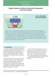
the stresses occurring on H/B. Fig. 1 shows an<br />
analysis model used. As can be understood from this<br />
diagram, we have learned th<strong>at</strong> the maximum stress<br />
occurs on both the flange tightening area and the<br />
chamfer area <strong>at</strong> the base of flange. Therefore, when<br />
developing the new bearing design, we have shifted a<br />
portion of the mass of the hub from a low stress region<br />
to a high stress region to mitig<strong>at</strong>e stress concentr<strong>at</strong>ion<br />
on the hub while not altering the design of critical areas<br />
including the raceway surface, disk and wheel<br />
receiving area.<br />
High stress region<br />
Fig. 1 Stress analysis on the hub bearing<br />
Low stress region<br />
<strong>SNR</strong> <strong>Product</strong> Innov<strong>at</strong>ion & Mech<strong>at</strong>ronic <strong>SNR</strong> Automotive Transmission Engineering <strong>SNR</strong> Automotive Equipment Engineering<br />
-34-
<strong>Eco</strong>-<strong>friendly</strong> <strong>Product</strong> <strong>Development</strong> <strong>at</strong> <strong>SNR</strong> <strong>Roulements</strong><br />
Fig. 2 shows shapes of a conventional design and<br />
the new optimized design. The new hub design<br />
fe<strong>at</strong>ures a unique flange shape, each of its bolt-down<br />
segments being reinforced with two ribs. With this<br />
design, the mass of outer ring has been reduced by<br />
20% and th<strong>at</strong> of entire H/B by 15%. This weight<br />
reduction will mean a maximum weight reduction of<br />
1,300 g per automobile axle.<br />
20% weight<br />
reduction<br />
Fig. 2 Conventional design (left) and new optimized<br />
design (right)<br />
2.2 W<strong>at</strong>er pump bearing for automobile<br />
Fig. 4 shows an appearance of a conventional w<strong>at</strong>er<br />
pump for cooling an automotive engine, and Fig. 5<br />
schem<strong>at</strong>ically illustr<strong>at</strong>es the structure of the w<strong>at</strong>er<br />
pump. Many present-day w<strong>at</strong>er pumps used for cooling<br />
modern automotive engines incorpor<strong>at</strong>e integral shaft<br />
bearings th<strong>at</strong> have a raceway surface on their shafts<br />
with their inner ring deleted.<br />
With a conventional structure in Fig. 5, the belt<br />
tension poses an offset load onto the bearing and<br />
causes the contact pressure to be gre<strong>at</strong>er. This<br />
problem in turn poses a challenge in providing longer<br />
life for the bearing. At the same time, resultant<br />
misalignment of the bearing rel<strong>at</strong>ive to the shaft can<br />
cause w<strong>at</strong>er to pass the seal and enter the bearing.<br />
Consequently, the grease can leak out of the bearing,<br />
leading to poor lubric<strong>at</strong>ion of the bearing. The bearing<br />
can then develop abnormal noise and/or exhibit<br />
excessively short life.<br />
2.1.2 Performance of new optimized design<br />
As described above, the new optimized design<br />
boasts a much reduced weight, while its rigidity is<br />
equivalent to th<strong>at</strong> of conventional designs.<br />
Furthermore, because the bolt-down segments are<br />
reinforced with ribs, the stress occurring <strong>at</strong> the flange<br />
base of the new design is 35% smaller as shown in<br />
Fig. 3.<br />
Pulley<br />
Drain hole<br />
Seal<br />
Pump rotor<br />
35% reduction<br />
in stress<br />
Drive shaft<br />
Stress<br />
Hub (pulley sheet)<br />
Pump body<br />
Fig. 4 View of W<strong>at</strong>er pump<br />
Conventional design<br />
New optimized design<br />
Load from belt<br />
Fig. 3 Stress analysis results<br />
Integral shaft bearing<br />
Fig. 5 W<strong>at</strong>er pump structure<br />
-35-
<strong>NTN</strong> TECHNICAL REVIEW No.772009<br />
2.2.1 Structure of new bearing<br />
In order to achieve lower running noise, lighter<br />
weight and longer bearing life, we have developed a<br />
novel external bearing th<strong>at</strong> has a shaft integr<strong>at</strong>ed with<br />
a flange. Fig. 6 shows a view of this novel external<br />
bearing, and Fig. 7 schem<strong>at</strong>ically illustr<strong>at</strong>es the<br />
structure of this bearing. This structure ensures th<strong>at</strong><br />
the tension from the drive belt acts on the center of<br />
bearing, helping prevent misalignment of the bearing<br />
rel<strong>at</strong>ive to the shaft. Compared with conventional<br />
designs, the contact pressure between the balls and<br />
raceway surface on this bearing is lower, leading to<br />
improved bearing durability. In addition, because our<br />
new bearing is free from bearing-shaft misalignment<br />
which will develop moment load, the balls will roll <strong>at</strong> the<br />
bottom of groove, resulting in lower running noise<br />
occurrence.<br />
Through improvement in our production technology,<br />
we have integr<strong>at</strong>ed the bearing and flange with the<br />
shaft, thereby we have successfully achieved an<br />
increase in load carrying capacity of bearing, increase<br />
in pump capacity, longer bearing life, lower noise<br />
emission and lighter weight. Fig. 8 summarizes<br />
changes in appearance and weight of w<strong>at</strong>er pump<br />
bearing over several years.<br />
2.2.2 Determin<strong>at</strong>ion of contact pressure occurring<br />
between balls and raceway surface<br />
So th<strong>at</strong> a w<strong>at</strong>er pump on an automobile remains<br />
oper<strong>at</strong>ive without any need for repair until the<br />
automobile reaches the end of its useful service life,<br />
the life of w<strong>at</strong>er pump bearing needs to s<strong>at</strong>isfy 310 5<br />
Flange<br />
Load from belt<br />
Shaft<br />
External bearing<br />
Fig. 6 View of external bearing<br />
Fig. 7 Structure of external bearing<br />
Gre<strong>at</strong>er pump capacity<br />
Longer life<br />
Weight reduction<br />
Drive belt for auxiliaries is directly engaged with the outer ring; this arrangement<br />
helps realize a space-saving pump design.<br />
Use of larger balls helps reduce contact pressure, mitig<strong>at</strong>ing adverse effect of<br />
press-fitting oper<strong>at</strong>ion.<br />
21%<br />
Optimiz<strong>at</strong>ion of w<strong>at</strong>er pump<br />
571g<br />
Improvements<br />
• Gre<strong>at</strong>er load carrying<br />
capacity with bearing<br />
• Pump capacity<br />
• Bearing life<br />
• Noise level<br />
• Weight<br />
451g<br />
2004 2008<br />
Years<br />
Fig. 8 Process of w<strong>at</strong>er pump bearing<br />
-36-
<strong>Eco</strong>-<strong>friendly</strong> <strong>Product</strong> <strong>Development</strong> <strong>at</strong> <strong>SNR</strong> <strong>Roulements</strong><br />
km of automobile’s total travel distance. In order for a<br />
given w<strong>at</strong>er pump bearing design to s<strong>at</strong>isfy this life<br />
requirement, its internal design needs to be finalized so<br />
th<strong>at</strong> the contact pressure <strong>at</strong> any portion in it does not<br />
exceed f<strong>at</strong>igue limit of th<strong>at</strong> portion. To this end, it is<br />
also important to optimize tightening allowance of the<br />
seal, amount of prefilled grease, and loc<strong>at</strong>ion of<br />
prefilled grease.<br />
We have studied various parameters including<br />
bearing life, temper<strong>at</strong>ure, parts tolerances, minimum<br />
and maximum clearances, and tightening allowance,<br />
executed functional test, and various tests with the<br />
pump lifetime tester shown in Fig. 9, thereby we have<br />
established the design standard th<strong>at</strong> s<strong>at</strong>isfies the<br />
bearing life requirement.<br />
automotive transmission is gre<strong>at</strong>ly affected by torque<br />
loss occurring from an inactive idler gear: therefore,<br />
bearing torque poses a critical factor in the torque loss<br />
on the transmission.<br />
The efforts <strong>SNR</strong> has so far made with its<br />
transmission bearings in order to reduce CO2<br />
emissions are as follows:<br />
(1) The inner and outer rings and rolling elements of<br />
our bearings made of the standard steel m<strong>at</strong>erial<br />
100Cr6 are now subjected to a special he<strong>at</strong><br />
tre<strong>at</strong>ment process. Consequently, these<br />
components boast longer life even under severe<br />
lubric<strong>at</strong>ing conditions.<br />
(2) <strong>Development</strong> of unique self-lubric<strong>at</strong>ing bearings for<br />
automotive gearboxes (Fig. 10 shows examples of<br />
self-lubric<strong>at</strong>ing bearing lubric<strong>at</strong>ed with solid<br />
lubricant).<br />
(3) Decreased torque by superseding sliding bearings<br />
for idler gear with rolling bearings such as caged<br />
needle roller bearing.<br />
(4) Optimized bearing design through analysis for load<br />
and torque on transmission bearing by using newly<br />
developed engineering comput<strong>at</strong>ion software (a<br />
simul<strong>at</strong>ion model is shown in Fig. 11).<br />
(5) Reduced frictional torque through improved internal<br />
design for bearings.<br />
Fig. 9 View of pump lifetime test<br />
3. Efforts for bearing products of lower<br />
torque<br />
This section describes our efforts for low torque<br />
designs with automotive transmission bearings, hub<br />
bearings and suspension bearings.<br />
3.1 Automotive transmission bearings<br />
Various improvement activities have been performed<br />
by people involved in automotive technologies to help<br />
improve operability of automotive transmissions and<br />
reduce CO2 emissions from automobiles. To promote<br />
various automotive transmission systems, <strong>SNR</strong> has<br />
been committed to lighter weight, higher efficiency<br />
(lower torque) transmission bearing designs.<br />
Approx. 50% of torque loss occurring on a given<br />
automotive transmission results from stirring-induced<br />
resistance with lubric<strong>at</strong>ing oil. Therefore, an<br />
appropri<strong>at</strong>e choice of lubric<strong>at</strong>ing oil is one of important<br />
consider<strong>at</strong>ions in achieving lower torque on an<br />
automotive transmission, and a currently more favored<br />
combin<strong>at</strong>ion is a use of minimum amount of low<br />
viscosity lubric<strong>at</strong>ing oil. Incidentally, efficiency of an<br />
Fig. 10 Autonomous bearings using solid lubricant<br />
Fig. 11 Transmission simul<strong>at</strong>ion<br />
-37-
<strong>NTN</strong> TECHNICAL REVIEW No.772009<br />
3.2 Low torque ball bearings<br />
To reduce friction-induced torque loss on an<br />
automotive transmission, use of a ball bearing r<strong>at</strong>her<br />
than a tapered roller bearing is advantageous.<br />
However, since load carrying capacity of a ball bearing<br />
is smaller compared with a tapered roller bearing, the<br />
size of ball bearing tends to be larger so th<strong>at</strong> the<br />
bearing can s<strong>at</strong>isfy targeted life. Incidentally, the<br />
ordinary fracture mode of transmission bearing is<br />
surface damage starting from a dent mark on the<br />
raceway owing to lubricant contamin<strong>at</strong>ed with foreign<br />
m<strong>at</strong>ter, r<strong>at</strong>her than f<strong>at</strong>igue failure of bearing m<strong>at</strong>erial.<br />
Therefore, to prevent ingress of foreign m<strong>at</strong>ter into a<br />
bearing to ensure longer bearing life, a bearing having<br />
filter seals shown in Fig. 12 is used. Filter seals need<br />
to be optimally designed so th<strong>at</strong> they not only provide<br />
good filtering performance but also allow lubric<strong>at</strong>ing oil<br />
to be introduced into the bearing to lubric<strong>at</strong>e and cool<br />
down the bearing.<br />
Many bearings with filter seals fe<strong>at</strong>ure an increased<br />
bearing width dimension to accommod<strong>at</strong>e an additional<br />
elastomer filter seal; however, this configur<strong>at</strong>ion leads<br />
to increased frictional torque on bearing. A novel<br />
design developed by <strong>SNR</strong>, as shown in Fig. 13 has a<br />
clipped double polyamide cage th<strong>at</strong> has filtering<br />
function. The advantages of this design are as follows:<br />
(1) Compact and light-weight design is possible.<br />
(2) Labyrinth clearance between the cage and<br />
raceway can be controlled <strong>at</strong> higher precision.<br />
(3) Provision of two oil inlets helps increase<br />
lubric<strong>at</strong>ing oil flow into the bearing.<br />
(4) Reduced cost<br />
The result of comparison between our newly<br />
developed double seal design and a conventional seal<br />
design is described below.<br />
Fig. 14 illustr<strong>at</strong>es results of measurement of oil flow<br />
through a bearing under oil b<strong>at</strong>h lubric<strong>at</strong>ion<br />
environment. The d<strong>at</strong>a mapped along the vertical axis<br />
represent filtering effect and oil flow th<strong>at</strong> passes a filter<br />
and contribute to lubric<strong>at</strong>ion. Compared with a<br />
conventional filter seal, our newly developed double<br />
filter seals boast better lubric<strong>at</strong>ion efficiency as more<br />
oil flows through the bearing though the filtering effect<br />
is roughly same.<br />
Fig. 15 illustr<strong>at</strong>es a result of comparing running<br />
torque of our newly developed bearing with double<br />
filter seals to th<strong>at</strong> of conventional bearing. Torque<br />
occurring inside the bearing including rolling resistance<br />
is virtually the same with both bearing types;<br />
notwithstanding, the total torque on our new bearing<br />
design has been reduced by 65% because the torques<br />
occurring on the seals has been gre<strong>at</strong>ly reduced. Also,<br />
he<strong>at</strong> buildup in our bearing is mitig<strong>at</strong>ed; consequently,<br />
our bearing boasts improved seizure resistance.<br />
Furthermore, filtering function of our bearing is virtually<br />
equivalent to th<strong>at</strong> of conventional bearing design, and<br />
the width of our bearing can be smaller. Our bearing<br />
design can be applied to produce compact, light-weight<br />
transmission bearing products.<br />
Oil flow<br />
Filtering effect and oil flow<br />
Running torque Nm<br />
0.350<br />
0.300<br />
0.250<br />
0.200<br />
0.150<br />
0.100<br />
0.050<br />
0.000<br />
Fig. 12 Bearing with filter seals<br />
15.5<br />
Filter seal<br />
(conventional<br />
design)<br />
Double<br />
filter seals<br />
(new design)<br />
Fig. 14 Efficiency against pollution<br />
Conventional<br />
design<br />
Fig. 15 Torque test results<br />
Clipped double<br />
polyamide cage<br />
Fig. 13 Bearing with double filter seals into a clipped<br />
double polyamid cage<br />
Filtering effect<br />
Oil flow<br />
Bearing interior<br />
Seal<br />
65%<br />
reduction<br />
New design<br />
-38-
<strong>Eco</strong>-<strong>friendly</strong> <strong>Product</strong> <strong>Development</strong> <strong>at</strong> <strong>SNR</strong> <strong>Roulements</strong><br />
3.3 Low torque tapered roller bearings<br />
Tapered roller bearings are often used as<br />
transmission bearings because they can carry a<br />
gre<strong>at</strong>er combined axial and radial load compared with<br />
other bearing types of similar size. However, reduction<br />
in frictional torque occurring on this bearing type poses<br />
a challenge.<br />
The <strong>SNR</strong> tapered roller bearings for automotive<br />
transmissions boasts decreased frictional torque<br />
through adoption of <strong>NTN</strong>’s design and production<br />
technologies for low torque tapered roller bearings.<br />
The advantages of these <strong>SNR</strong> products can be defined<br />
as follows:<br />
(1) Special he<strong>at</strong> tre<strong>at</strong>ment process helps improve<br />
f<strong>at</strong>igue strength and resistance against dent mark<br />
th<strong>at</strong> can result from foreign m<strong>at</strong>ter in lubricant.<br />
(2) Adoption of polyamide cage in which shear friction<br />
with oil is lower, compared with th<strong>at</strong> in standard<br />
steel sheet cages<br />
(3) Improved design for bearing interior in order to<br />
improve load carrying capacity and rigidity and<br />
mitig<strong>at</strong>e misalignment and frictional torque<br />
(optimized number and size of rollers, and special<br />
crowning on raceway surface and rolling surface)<br />
(4) Optimiz<strong>at</strong>ion of contact loc<strong>at</strong>ions between inner ring<br />
flange surface, rollers, and raceway surface<br />
(5) Reduction in surface roughness of inner ring flange<br />
surface and roller end faces to reduce frictional<br />
torque on roller end faces<br />
Fig. 16 graphically plots inform<strong>at</strong>ion about<br />
comparisons of <strong>SNR</strong>'s tapered roller bearing for<br />
transmission and a competitor’s tapered roller bearing,<br />
wherein the running speeds d<strong>at</strong>a of these bearings are<br />
plotted along the horizontal axis. As can be understood<br />
from this diagram, the bearing products of <strong>SNR</strong> boast<br />
25 to 50% reduction in torque loss, compared with<br />
competitor’s products.<br />
25% reduction in torque loss with transmission<br />
bearings means 2 g/km reduction in CO2 emissions per<br />
vehicle. In addition, use of low torque tapered roller<br />
bearings helps improve seizure resistance as well as<br />
quality of shift-change oper<strong>at</strong>ion.<br />
3.4 Automotive hub bearings<br />
About 50% of frictional torque occurring on a wheel<br />
bearing results from sliding friction on contact surface<br />
of seal(s). Therefore, the use of hub bearings fe<strong>at</strong>uring<br />
reduced sliding resistance is effective in reducing the<br />
CO2 emissions from the vehicle th<strong>at</strong> incorpor<strong>at</strong>es low<br />
friction wheel bearings. However, reduced frictional<br />
resistance on a given seal often means jeopardized<br />
sealing performance of th<strong>at</strong> seal. Therefore, there has<br />
been a challenge of meeting conflicting needs for<br />
reduced frictional resistance and improved sealing<br />
performance.<br />
<strong>SNR</strong> has developed a unique tribological effectcapable<br />
seal th<strong>at</strong> boasts approx. 11% reduction in<br />
sliding resistance and 22% improvement in sealing<br />
performance, by improving lubric<strong>at</strong>ion quality on the<br />
sliding surface of seal lip. As <strong>SNR</strong> has applied the<br />
above-mentioned development concept to its currently<br />
present seal products, cost reduction and reduced<br />
development lead time have been achieved.<br />
3.4.1 Advantages of tribological effect-capable<br />
seal products<br />
On our newly developed tribological effect-capable<br />
seals, the lip sliding surface of the slinger is uniquely<br />
shaped so th<strong>at</strong> oil film is readily formed on it.<br />
1.0<br />
Running torque Nm<br />
0.8<br />
0.6<br />
0.4<br />
Competitor’s tapered roller bearing<br />
0.2<br />
<strong>SNR</strong> low torque tapered roller bearing<br />
0<br />
0 200 400 600 800 1000 1200 1400 1600 1800 2000<br />
Running speed min -1<br />
Fig. 16 Torque measurements with rot<strong>at</strong>ions<br />
-39-
<strong>NTN</strong> TECHNICAL REVIEW No.772009<br />
Consequently, lower torque and mitig<strong>at</strong>ion of he<strong>at</strong><br />
buildup have been achieved. Fig. 17 illustr<strong>at</strong>es a<br />
cross-sectional plan of our seal, and a view of the<br />
contact area of the slinger. Micro-pores present in this<br />
contact area help form an oil film between the seal lip<br />
and slinger, and the oil film reduces friction on the seal<br />
lip. Furthermore, these micro-pores prevent wear<br />
caused by ingress and trapping of foreign m<strong>at</strong>ters.<br />
3.4.2 Performance of tribological effect-capable seal<br />
Figs. 18 and 19 show running torque and test<br />
results of a muddy w<strong>at</strong>er bearing life test with<br />
conventional seal and our newly developed tribological<br />
effect-capable seal. Owing to reduced resistance on<br />
seal, the running torque has decreased by 11%, and<br />
the muddy w<strong>at</strong>er bearing life has increased by 22%.<br />
Enlarged view of<br />
contact area<br />
on slinger<br />
Micro-pores<br />
3.5 Automotive suspension bearings<br />
To be able to oper<strong>at</strong>e without problems under<br />
severe oper<strong>at</strong>ing conditions (environments such as<br />
muddy w<strong>at</strong>er), a sealed strut bearing needs to fe<strong>at</strong>ure<br />
improved reliability and sealing performance. In<br />
challenging this issue, <strong>SNR</strong> has developed a unique<br />
low torque sealed strut bearing complete with a flo<strong>at</strong>ing<br />
seal in order to s<strong>at</strong>isfy requirements for both an<br />
improvement in running torque and sealing<br />
performance (Fig. 21).<br />
3.5.1 Fe<strong>at</strong>ures of sealed strut bearings<br />
Muddy w<strong>at</strong>er resistance of a bearing is governed by<br />
lip performance of its seal. Therefore, it is important to<br />
develop a seal th<strong>at</strong> is capable of s<strong>at</strong>isfying both better<br />
sealing performance and stabler running torque<br />
performance. To address this challenge, we have<br />
recently developed a novel low torque sealed strut<br />
bearing complete with a flo<strong>at</strong>ing seal. Fig. 20 shows a<br />
conventional design, and Fig. 21 illustr<strong>at</strong>es our new<br />
design. For comparison purpose, Fig. 22 shows a<br />
structure of a different design, th<strong>at</strong> is, an overmolded<br />
lip seal.<br />
Fig. 17 Seal shape on the slinger<br />
Torque Nm<br />
0.7<br />
0.6<br />
0.5<br />
0.4<br />
0.3<br />
0.2<br />
0.1<br />
0<br />
Conventional<br />
design<br />
Tribological<br />
effect-capable seal<br />
11% reduction<br />
in running<br />
torque<br />
Seal area<br />
Bearing area<br />
Fig. 20 Usual design<br />
Fig. 18 Comparison of rot<strong>at</strong>ional friction between<br />
development seal and current one<br />
Muddy w<strong>at</strong>er bearing life h<br />
700<br />
600<br />
500<br />
400<br />
300<br />
200<br />
100<br />
0<br />
Conventional design<br />
Tribological<br />
effect-capable seal<br />
22%<br />
Fig. 19 Comparison of muddy w<strong>at</strong>er resistance between<br />
development seal and current one<br />
Fig. 21 <strong>SNR</strong> design: flo<strong>at</strong>ing seal<br />
Fig. 22 Competitor design: overmolded lip seal<br />
-40-
<strong>Eco</strong>-<strong>friendly</strong> <strong>Product</strong> <strong>Development</strong> <strong>at</strong> <strong>SNR</strong> <strong>Roulements</strong><br />
3.5.2 Test results<br />
Fig. 23 illustr<strong>at</strong>es the contribution of a seal onto the<br />
running torque of a strut bearing. Compared with a<br />
conventional design, the running torque on our newly<br />
developed flo<strong>at</strong>ing seal (<strong>SNR</strong> design in Fig. 21) is 18%<br />
gre<strong>at</strong>er; compared with an overmolded lip seal, the<br />
running torque on our new seal design is 50% smaller.<br />
Fig. 24 provides results of muddy w<strong>at</strong>er test.<br />
Compared with the conventional design, our newly<br />
developed flo<strong>at</strong>ing seal (<strong>SNR</strong> design in Fig. 21) boasts<br />
gre<strong>at</strong>ly improved sealing performance th<strong>at</strong> helps<br />
positively reduce w<strong>at</strong>er ingress into the bearing.<br />
Though excellent in initial sealing performance, the<br />
overmolded lip seal experiences wear of the<br />
overmolded lip: the <strong>SNR</strong>’s newly developed design<br />
boasts 38% smaller w<strong>at</strong>er ingress.<br />
4. Afterword<br />
This article has provided an overview about lighterweight,<br />
lower-torque, and eco-<strong>friendly</strong> automotive<br />
bearing technologies of <strong>SNR</strong>. We have been<br />
committed to development of new technologies and<br />
products, aiming <strong>at</strong> further progress in light-weight and<br />
low-torque bearing designs, and, <strong>at</strong> the same time,<br />
remains involved in long-term projects for hybrid<br />
electric vehicles and pure electric vehicles.<br />
Seal area<br />
Bearing area<br />
Running torque<br />
50% reduction<br />
in running torque<br />
Reduction in w<strong>at</strong>er ingress %<br />
38% reduction<br />
in w<strong>at</strong>er ingress<br />
Usual<br />
design<br />
<strong>SNR</strong><br />
design<br />
Overmolded<br />
design<br />
Usual<br />
design<br />
<strong>SNR</strong><br />
design<br />
Overmolded<br />
design<br />
Fig. 23 Torque test results<br />
Fig. 24 Muddy w<strong>at</strong>er test results<br />
Photo of authors<br />
Siegfried RUHLAND<br />
Ludovic SAUNIER<br />
Cynthia TSEN<br />
Bernard LIATARD<br />
Gérald MIRABEL<br />
<strong>SNR</strong> <strong>Product</strong> Innov<strong>at</strong>ion<br />
& Mech<strong>at</strong>ronic<br />
<strong>SNR</strong> <strong>Product</strong> Innov<strong>at</strong>ion<br />
& Mech<strong>at</strong>ronic<br />
<strong>SNR</strong> <strong>Product</strong> Innov<strong>at</strong>ion<br />
& Mech<strong>at</strong>ronic<br />
<strong>SNR</strong> Automotive<br />
Transmission Engineering<br />
<strong>SNR</strong> Automotive<br />
Equipment Engineering<br />
-41-
![[New Product] Unit Products for Office Equipment - NTN](https://img.yumpu.com/27154451/1/184x260/new-product-unit-products-for-office-equipment-ntn.jpg?quality=85)
![[New Product] Development of Oil-impregnated Sintered ... - NTN](https://img.yumpu.com/27154427/1/184x260/new-product-development-of-oil-impregnated-sintered-ntn.jpg?quality=85)