
Create successful ePaper yourself
Turn your PDF publications into a flip-book with our unique Google optimized e-Paper software.
LCD-TFT Monitors<br />
<strong>LM5109</strong><br />
User <strong>Manual</strong><br />
<strong>LM5109</strong>D11<br />
Edition 01<br />
January 2005<br />
KROMA T E L E C O M<br />
Pol. Ind. Alcobendas - C/ La Granja, 80<br />
28108 Madrid - ESPAÑA<br />
Tel. (34-91) 661 45 14<br />
Fax. (34-91) 484 03 49<br />
e-mail: kromatelecom@kromatelecom.com
User <strong>Manual</strong> <strong>LM5109</strong><br />
INDEX<br />
1. FRONT PANEL ..................................................................................................................................2<br />
1.1. DESCRIPTION AND FUNCTIONS ...........................................................................................3<br />
2. REAR PANEL .....................................................................................................................................4<br />
2.1. DESCRIPTION AND FUNCTIONS OF EACH PART ..............................................................6<br />
3. CONNECTIONS..................................................................................................................................8<br />
3.1. EXTERNAL POWER SUPPLY ..................................................................................................8<br />
3.2. EXTERNAL AUDIO INPUTS ....................................................................................................8<br />
4. KEYBOARD........................................................................................................................................9<br />
4.1. KEYBOARD – HOW IT WORKS ............................................................................................10<br />
5. MENUS..............................................................................................................................................11<br />
5.1. STATUS MENU ........................................................................................................................11<br />
5.2. MEMORY RECALL MENU.....................................................................................................13<br />
5.3. SETUP MENU ...........................................................................................................................14<br />
4.3.1. MANUAL SETUP MENU......................................................................................................15<br />
4.3.1.1.CALIBRATION VALUES MENU....................................................................................15<br />
4.3.1.3. COLOUR SETTING MENU ............................................................................................16<br />
4.3.1.4. CAL WITH ACTIVE DATA ............................................................................................17<br />
4.3.1.5. SYSTEM OPTIONS CONFIGURATIONS MENU .........................................................17<br />
4.3.1.6. OSD LANGUAGE............................................................................................................18<br />
5.4. PASSWORD MENU..................................................................................................................19<br />
4.4.1. EXPLANATORY NOTE ON PASSWORDS .........................................................................20<br />
5.5. TECHNICAL MENU.................................................................................................................20<br />
5.6. MEMORY STORE MENU ........................................................................................................21<br />
5.7. PROGRAM FUNCTION MENU ..............................................................................................22<br />
5.8. EMBEDDED AUDIO MENU (SDI ONLY) .............................................................................24<br />
- 1 -
User <strong>Manual</strong> <strong>LM5109</strong><br />
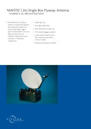
1. FRONT PANEL<br />
E<br />
D<br />
A<br />
B<br />
C<br />
A) Switching on/off<br />
B) Calibration Led<br />
C) Optical Encoder<br />
D) Keyboard<br />
E) Screen Protective Film<br />
- 2 -
User <strong>Manual</strong> <strong>LM5109</strong><br />
1.1. DESCRIPTION AND FUNCTIONS<br />
Switching on/off<br />
A lighted green led, located above the switcher, will indicate that equipment is<br />
operative.<br />
Calibration led<br />
The calibration led will be on when operative values of the equipment and its<br />
default ones mismatch. If they both are the same, it´ll be off.<br />
Depending on the input, parameters that are taken into account are:<br />
- Brightness, contrast and saturation for PAL/SECAM video inputs.<br />
- Brightness, contrast, saturation and hue for NTSC video inputs.<br />
- Brightness and contrast for SDI video inputs and PC input (RGB).<br />
Optical encoder<br />
Optical encoder is used for moving thru the menus and varying system values.<br />
When moved clockwise, values will be increased.<br />
Keyboard<br />
Keys allow user to directly operate the equipment with entering the menu.<br />
Screen Protective Film<br />
In order to avoid the screen being hit or damaged from external agressions, a<br />
resistant protective plastic film has been attached. It is anti-reflective as well. As it<br />
is adhered, it might be replaced for a new one if needed.<br />
Note that a transparent thin film covers the equipment when departs from<br />
<strong>Kroma</strong>. Kindly remove it to start working with the TFT Monitor.<br />
- 3 -
User <strong>Manual</strong> <strong>LM5109</strong><br />
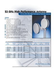
2. REAR PANEL<br />
J<br />
I<br />
D<br />
F<br />
C<br />
J<br />
E<br />
A<br />
G<br />
I<br />
H<br />
B<br />
- 4 -
User <strong>Manual</strong> <strong>LM5109</strong><br />
A) Power Supply<br />
B) Serial Number.<br />
C) Audio Inputs.<br />
D) Software upgrade connector<br />
E) Composite video inputs (A, B)<br />
F) SDI video input (S1, optional)<br />
G) Protective gears for BNC connectors<br />
H) Battery support<br />
I) Power supply selection<br />
J) Termination for composite video inputs<br />
- 5 -
User <strong>Manual</strong> <strong>LM5109</strong><br />
2.1. DESCRIPTION AND FUNCTIONS OF EACH PART<br />
Power supply<br />
This equipment can be powered from the mains thru external power supply. For<br />
this option, switch “I” to DC-IN mode.<br />
Serial number<br />
This label distinguished three parts:<br />
- Serial number of the equipment.<br />
- Options activated (CCVS and/or SDI modules).<br />
Audio inputs<br />
This equipment is provided with two analogue audio inputs. They can be output<br />
thru the built-in speaker at a side of the monitor.<br />
Composite video inputs<br />
This equipment is provided with two composite video inputs (CCVS A, CCVS<br />
B) for PAL, PAL-M, NTSC or SECAM signals.<br />
SDI inputs<br />
This equipment is provided with one SDI video input (S1) with passive loopthrough<br />
(75 Ω load). If loop remains unused, line must be terminated with a 75-<br />
Ohm load.<br />
Protective gears for BNC connectors<br />
This equipment is provided with two security bows for protecting the BNC<br />
connectors from accidental bumps.<br />
Battery support<br />
This equipment can be powered with the following batteries:<br />
- Anton Bauer.<br />
- Sony (type BP).<br />
For this option, switch “I” to BAT mode.<br />
- 6 -
User <strong>Manual</strong> <strong>LM5109</strong><br />
Power supply selection<br />
This equipment can be powered either thru mains or batteries. User might select<br />
the type of power supply thru the switcher.<br />
Termination<br />
Each CCVS video input consists of two connectors for passive looping. If not<br />
used, switch the termination (“J”) from HI to 75 Ω.<br />
- 7 -
User <strong>Manual</strong> <strong>LM5109</strong><br />
3. CONNECTIONS<br />
3.1. EXTERNAL POWER SUPPLY<br />
This equipment can be powered from an external power supply. See below the<br />
pinout. Note that switcher (“I”) must be at DC IN mode.<br />
• Pins 1 and 2: +12 V DC.<br />
• Pins 3 and 4: GND.<br />
3.2. EXTERNAL AUDIO INPUTS<br />
This equipment is provided with two connectors for external audio signal<br />
monitoring. Pinout is as follows:<br />
• Pin 1: Audio signal +.<br />
• Pin 2: Audio signal -.<br />
• Pin 3: GND.<br />
Audio inputs are designed to receive balanced signals. For a “single-ended”<br />
connection, use input + and connect input – to GND.<br />
- 8 -
User <strong>Manual</strong> <strong>LM5109</strong><br />
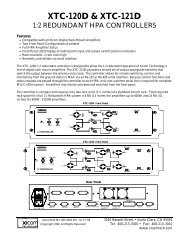
4. KEYBOARD<br />
Keys allow user to directly operate the equipment without entering the menus.<br />
<br />
<br />
<br />
<br />
<br />
<br />
CCVS: Composite video input selection. First keystroke will indicate the chosen<br />
video input. Second and successive will change the video inputs. A message on<br />
screen will show the chosen input, its presence or not, and its format. After a while<br />
(or pressing ESC), this message will disappear.<br />
CDV: SDI video input selection. If SDI option is activated, a message will appear<br />
indicating this input and its presence or not. If the SDI option is not installed, a<br />
message indicating a non-activated option will appear. After a while (or pressing<br />
ESC), this message will disappear.<br />
CNT: Contrast control. A keystroke will show actual value and if matches<br />
calibrated values (CAL) or not (UNCAL). Vary this parameter with the optical<br />
encoder (“C” at the front panel). Press CAL to calibrate contrast. After a while (or<br />
pressing ESC), this message will disappear.<br />
BLK: Brightness control. A keystroke will show actual value and if matches<br />
calibrated values (CAL) or not (UNCAL). Vary this parameter with the optical<br />
encoder (“C” at the front panel). Press CAL to calibrate brightness. After a while (or<br />
pressing ESC), this message will disappear.<br />
SAT: Saturation Control. Used only with composite video signals. A keystroke<br />
will show actual value and if matches calibrated values (CAL) or not (UNCAL).<br />
Vary this parameter with the optical encoder (“C” at the front panel). Press CAL to<br />
calibrate saturation. After a while (or pressing ESC), this message will disappear.<br />
VOL: Volume Control. For varying volume level of the following two signals:<br />
- Speaker volume, at a side of the monitor.<br />
- Audio extracted from the signal is adapted towards the speaker. The volume of<br />
this signal can be changed as well. Sometimes it´s advisable to adjust both levels<br />
to get a perfect audio monitoring.<br />
This VOL key is configurable thru PROGRAM FUNCTION menu.<br />
<br />
AUD: Configurable thru PROGRAM FUNCTION menu. It might have the<br />
following uses:<br />
- 9 -
User <strong>Manual</strong> <strong>LM5109</strong><br />
- Access to EMBEDDED AUDIO menu. A keystroke will make this menu<br />
appear without entering Status Menu.<br />
- Selection of De-embedded Audio Channel: For choosing the different<br />
channels (1, 2, 3, 4) that will be output out of the embedded audio.<br />
First keystroke will indicate the chosen audio channel. Second and successive<br />
will change the audio outputs. After a while (or pressing ESC), this message will<br />
disappear.<br />
- Selection of External Audio Signal: For choosing the different audio signals<br />
(embedded audio, external 1, external 2) that will be output thru the speaker.<br />
First keystroke will indicate the chosen output. Second and successive will<br />
change it.<br />
<br />
<br />
<br />
STS: Access to System menu<br />
ESC: Cancel or exit an operation.<br />
CAL: For returning to calibrated values or selecting a menu option.<br />
Nota that if pressed during 2+ seconds, calibration will affect all system<br />
parameters.<br />
4.1. KEYBOARD – HOW IT WORKS<br />
‣ Numbers above the keys are aimed at entering user passwords and numeric data<br />
(such as network “ID” of the monitor or module activation codes).<br />
‣ There is no need to wait that a message disappear. If needed, press another key<br />
even if a message remains on screen. It´ll automatically operate according to the<br />
second key function.<br />
- 10 -
User <strong>Manual</strong> <strong>LM5109</strong><br />
5. MENUS<br />
Menus allow the user to view, configure, store and call system values. Press STS<br />
key (Status) at the front panel as follows:<br />
Read below about the different menus that will be available.<br />
5.1. STATUS MENU<br />
STATUS menu is the main menu as it allows access to all operations.<br />
To enter a menu, move the optical encoder (“C” at the fron panel) to the desired<br />
menu. Then press CAL.<br />
For example, if we want to enter SETUP menu, move the optical encoder clockwise<br />
to increase the selection window:<br />
Then press CAL to enter the desired menu.<br />
- 11 -
User <strong>Manual</strong> <strong>LM5109</strong><br />
For escaping the menu, press ESC and it´ll disappear.<br />
When STS key is pressed twice, CONFIGURATION VALUES menu will appear.<br />
See below:<br />
This menu shows actual configuration of the equipment. It consists of:<br />
- BOARDS: It shows the installed and activated options. AUD and CCVS<br />
will always be installed and activated while others will depend on the<br />
equipment characteristics.<br />
• AUD: two analogue audio inputs (AUDIO CH1, CH2).<br />
• CCVS: two analogue video inputs (CCVS A, B).<br />
• CDV: one SDI video input (S1).<br />
- VERSION: It shows the softare version installed. Note that they might be<br />
upgraded * .<br />
- SYSTEM: It shows some hardware error. If none, an OK will appear. If yes,<br />
an error code will appear * .<br />
* Check with your supplier<br />
- 12 -
User <strong>Manual</strong> <strong>LM5109</strong><br />
- FPGA VERSION: It shows the FPGA configuration of the equipment. As<br />
it happens with the software version, it might be upgraded.<br />
- EQUIPMENT VALUES: Finally, different parameters of the equipment<br />
will appear (actual and calibration values).<br />
For exiting the menu, press STS or ESC.<br />
5.2. MEMORY RECALL MENU<br />
Secuencia de acceso<br />
MEMORY RECALL menu allows the user to load the values previously stored at<br />
the four user memories (or the technical memory as well). Parameters recovered are:<br />
- Control values (brightness, contrast, saturation...) and calibration values.<br />
- Audio values (volume, group and audio output channel).<br />
- Values of PROGRAM FUNCTION menu.<br />
With the optical encoder, simply place the selection window at the desired memory<br />
to recall. Then press CAL. A message about recovery progress will appear and if it has<br />
been done correctly (DONE /ERROR).<br />
Steps to recall user memory 1<br />
- 13 -
User <strong>Manual</strong> <strong>LM5109</strong><br />
For exiting the menu, press ESC.<br />
Notes<br />
Have in mind that, unless changed by user, all memories are set with the technical<br />
values.<br />
5.3. SETUP MENU<br />
Steps to access Setup menu<br />
SETUP menu allows the user to change the following parameters of the equipment:<br />
- Calibration Values (CALIBRATION VALUES MENU).<br />
- Colorimetry Values (COLOUR SETTINGS).<br />
- Calibration of the equipment with the actual values (CAL WITH ACTIVE<br />
DATA).<br />
- Configuration of the installed options of the equipment (CONFIG.<br />
OPTIONS).<br />
- Configuration of the OSD language (OSD LANGUAGE).<br />
For having access to these posibilities, a password needs to be entered. This way, no<br />
unauthorized user can modify the equipment values.<br />
Password requested is of the system. For entering it, use the numbers above the keys.<br />
- 14 -
User <strong>Manual</strong> <strong>LM5109</strong><br />
If password is right, user will enter MANUAL SETUP menu. If wrong, she will<br />
return to STATUS menu.<br />
4.3.1. MANUAL SETUP MENU<br />
From this menu, equipment values can be edited and/or modified.<br />
4.3.1.1.CALIBRATION VALUES MENU<br />
Access sequence<br />
CALIBRATION VALUES menu allow the user to modify contrast, brightness,<br />
saturation (only analogue CCVS), hue (only NTSC) and dimmer.<br />
Every time real (A) and calibrated (C) values of the parameter where window is<br />
located will be shown.<br />
For modifyng a parameter, select it thru the optical encoder (C at the front panel).<br />
Then press CAL key.<br />
Parameter modification sequence<br />
- 15 -
User <strong>Manual</strong> <strong>LM5109</strong><br />
When selected, parameter appears in red. Vary its value with the optical encoder.<br />
Press again CAL to validate the value. Press ESC to return to the previous value.<br />
Changed value will not be stored. For going back to MANUAL SETUP menu, press<br />
ESC.<br />
4.3.1.3. COLOUR SETTING MENU<br />
Access sequence<br />
COLOUR SETTING menu allows user to modify each RGB component separately<br />
from its reference value.<br />
For modifyng a parameter, select it thru the optical encoder (C at the front panel).<br />
Then press CAL key.<br />
Parameter modification sequence<br />
- 16 -
User <strong>Manual</strong> <strong>LM5109</strong><br />
Use the optical encoder for modifying its value. And CAL for validating it. Press<br />
ESC to return to the previous value. RESET SETTINGS option brings every parameter<br />
to the original value. Press ESC to go back to the menu.<br />
4.3.1.4. CAL WITH ACTIVE DATA<br />
CAL WITH ACTIVE DATA option allows the user to change calibration values.<br />
Choose this option with the optical encoder (C at the front panel) and press CAL.<br />
Calibration sequence<br />
If process is properly done, a “DONE” message will appear. If not, it´ll be an<br />
“ERROR”. Press ESC to return to STATUS menu.<br />
4.3.1.5. SYSTEM OPTIONS CONFIGURATIONS MENU<br />
Access sequence<br />
- 17 -
User <strong>Manual</strong> <strong>LM5109</strong><br />
SYSTEM OPTIONS CONFIGURATIONS menu allows user to activate the video<br />
inputs that were not activated when acquired. A 4-character code will be requested. This<br />
password is unique for every equipment. Follow these steps:<br />
1) For ordering the activation code, let your distributor know the Serial Number of the<br />
equipment.<br />
2) Enter the menu, then the code and press CAL.<br />
3) If code is the right one, equipment will reboot with the option activated. If not, an<br />
“Error” message will appear.<br />
4) There is one code for Analogue and another for activating the SDI video inputs.<br />
Each one is unique because it depends on the serial number of the monitor.<br />
Press ESC to return to the MANUAL SETUP menu.<br />
4.3.1.6. OSD LANGUAGE<br />
By default, language is English.<br />
Access sequence<br />
OSD LANGUAGE menu allows the user to select the language for the On-Screen-<br />
Display menu. Use the optical encoder, place on the desired language and press CAL.<br />
Equipment will be rebooted and all menus will appear on the desired language.<br />
- 18 -
User <strong>Manual</strong> <strong>LM5109</strong><br />
5.4. PASSWORD MENU<br />
Access sequence<br />
PASSWORD menu allows the user to modify the passwords of user memories (from<br />
1 to 4) and system password. Place on the memory whose password we need to change<br />
and press CAL:<br />
Password change<br />
Old password will be requested. This prevents any authorized user from entering:<br />
Old password request<br />
The window tells on which user memory we are entering.<br />
If password is not right, an “Error” message will appear and we return to the<br />
PASSWORD menu. If right, the new password is requested.<br />
- 19 -
User <strong>Manual</strong> <strong>LM5109</strong><br />
New password request<br />
Once entered, confirmation is needed to activate the new password.<br />
Password confirmation<br />
If the confirmation matches the new password, this will be the new one. If not, the<br />
old one will be kept.<br />
Once the process is finished, user returns to PASSWORD menu.<br />
Press ESC for exiting PASSWORD menu and return to STATUS.<br />
4.4.1. EXPLANATORY NOTE ON PASSWORDS<br />
Initially, every memory requires this password: 1234.<br />
5.5. TECHNICAL MENU<br />
Access sequence<br />
Access to the TECHNICAL menu is only allowed to KROMA TELECOM<br />
Engineering Department.<br />
- 20 -
User <strong>Manual</strong> <strong>LM5109</strong><br />
5.6. MEMORY STORE MENU<br />
Access sequence<br />
MEMORY STORE menu allows the user to save the equipment values onto the four<br />
user memories (and the technical one as well). They can be recovered from MEMORY<br />
RECALL menu if needed. The following parameterd can be stores:<br />
- Control (brightness, contrast, saturation, etc.) and calibration values.<br />
- Audio values (volume, group and analogue channels, group and AES-EBU<br />
channels).<br />
- Geometry values (h-shift, v-shift, etc.).<br />
- PROGRAM FUNCTION menu values.<br />
Note that technical menu cannot be altered. That way, technical parameters will be<br />
always available to the user. “All Memories” option is only allowed to technical people<br />
from KROMA.<br />
For using one user memory, use the optical encoder and select one of the four<br />
available by pressing CAL.<br />
For preventing unauthorized users, its password is requested. If right, actual values of<br />
the equipment will be stored on that user memory. If wrong, user will be returned to the<br />
MEMORY STORE menu.<br />
- 21 -
User <strong>Manual</strong> <strong>LM5109</strong><br />
A text on the recovery process will appear as well as a Done/Error message. .<br />
Storing sequence<br />
Press ESC for exiting MEMORY STORE menu and returning to the STATUS menu.<br />
5.7. PROGRAM FUNCTION MENU<br />
Access sequence<br />
PROGRAM FUNCTION menu allows the user to set certain parameter of the<br />
equipment, such as:<br />
- DECODER: for selecting PAL/NTSC or SECAM. To be used with<br />
composite video signals. Press CAL to activate.<br />
- 22 -
User <strong>Manual</strong> <strong>LM5109</strong><br />
- FILTER: for selecting the output filter of the decoder: COMB or NOTCH.<br />
To be used with composite video signals. Use the optical encoder and press<br />
CAL to activate.<br />
- AFC: for using video signals from VTRs in FAST mode. To be used with<br />
composite video signals. Use the optical encoder and press CAL to activate.<br />
- AGC: Automatic Gain Control. If ON, certain values will be established for<br />
the output signal, no matter the values of the input signal. To be used with<br />
composite video signals. Use the optical encoder and press CAL to activate.<br />
- COLOUR: To be used with composite video signals. It can be AUTO<br />
(colour will be adjusted to the saturation value) or MONO (picture will<br />
appear balck and white). Note that MONO option does not allow user to vary<br />
the saturation. Use the optical encoder and press CAL to activate.<br />
- APERTURE: Apreture control. To be used with composite video signals.<br />
Use the optical encoder and press CAL. A new menu will appear:<br />
With the optical encoder, place on the value and press CAL to activate.<br />
We´ll be returned to the PROGRAM FUNCTION menu. By pressing ESC,<br />
user will be also returned to the PROGRAM FUNCTION menu.<br />
- HUE: To be used with NTSC video signals.<br />
- AUD. KEY: For configuring the function of AUD key. By pressing CAL, a<br />
new menu will appear:<br />
- 23 -
User <strong>Manual</strong> <strong>LM5109</strong><br />
With the optical encoder, place on the value and press CAL to select the<br />
function of the AUD key. We´ll be returned to the PROGRAM FUNCTION<br />
menu. By pressing ESC, user will be also returned to the PROGRAM<br />
FUNCTION menu.<br />
For more information of this key, see Point 3 (on the keyboard).<br />
- VOL. KEY: for selecting which volume will be modified when this key is<br />
pressed.<br />
For more information of this key, see Point 3 (on the keyboard).<br />
- SIZE: Aspect ratio of the screen (4:3/16:9 or 4:3/16:9/5:4 for LM5018). This<br />
function appears only on the LM5009. LM5015 and LM5018 are provided<br />
with a SIZE key at the front panel). It can be used with composite and SDi<br />
video signals. Place on the value with the optical encoder and press CAL.<br />
Press ESC for exiting the menu.<br />
5.8. EMBEDDED AUDIO MENU (SDI ONLY)<br />
Acess sequence<br />
- 24 -
User <strong>Manual</strong> <strong>LM5109</strong><br />
EMBEDDED AUDIO menu displays information on the embedded audio and<br />
allows the user to select the group and how it will be output (analogue or AES-EBU).<br />
Thru the OSD user will see the groups (and their audio channels). An asterisk will<br />
inicate presence of audio.<br />
Example<br />
A red asterisk means STEREO, while a white one indicates MONO.<br />
The output of embedded audio signals will be selected thru channels, by selecting the<br />
desired group.<br />
See the esample above. There is audio at channels 1, 2, 3 and 4 of groups 1 (white<br />
asterisks, so MONO) and 2 (red asterisks, so STEREO). If we want to output the<br />
channel 2 of group 1, press CAL to select such channel thru the optical encoder. Then<br />
press CAL to activate.<br />
This menu is updated continuously.<br />
Press ESC to exit the menu.<br />
Example of functioning<br />
- 25 -