warning!
warning!
warning!

Create successful ePaper yourself
Turn your PDF publications into a flip-book with our unique Google optimized e-Paper software.
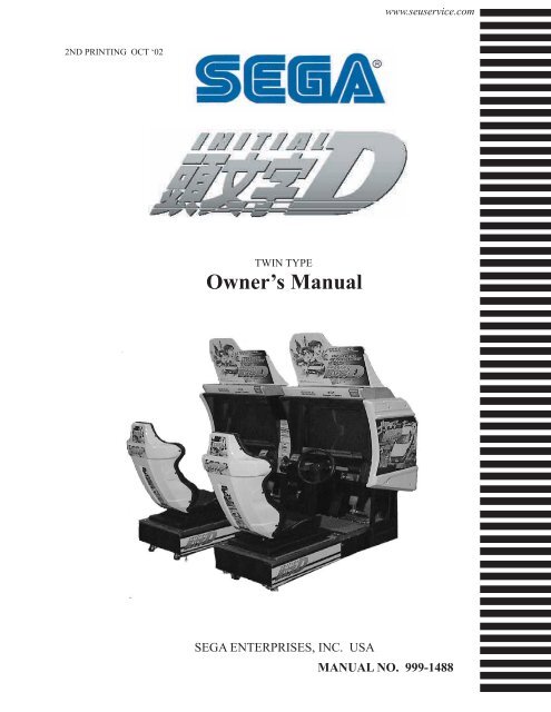
www.seuservice.com<br />
2ND PRINTING OCT ‘02<br />
TWIN TYPE<br />
Owner’s Manual<br />
SEGA ENTERPRISES, INC. USA<br />
MANUAL NO. 999-1488
VISIT OUR WEBSITE!
BEFORE USING THE PRODUCT, BE SURE TO READ THE FOLLOWING:<br />
To maintain the safety:<br />
To ensure the safe usage of the product, be sure to read the following before using the product. The<br />
following instructions are intended for the users, operators and the personnel in charge of the operation<br />
of the product. After carefully reading and sufficiently understanding the <strong>warning</strong> displays and<br />
cautions, handle the product appropriately. Be sure to keep this manual nearby the product or elsewhere<br />
convenient for referring to it when necessary.<br />
Herein, explanations which require special attention are enclosed with dual lines. Depending on the<br />
potentially hazardous degrees, the terms of WARNING, CAUTION, etc. are used. Be sure to understand<br />
the contents of the displays before reading the text.<br />
WARNING!<br />
Indicates that mishandling the product<br />
by disregarding this <strong>warning</strong><br />
will cause a potentially hazardous<br />
situation which can result in death<br />
or serious injury.<br />
CAUTION!<br />
Indicates that mishandling the product<br />
by disregarding this caution will cause<br />
a slight hazardous situation which can<br />
result in personal injury and or material<br />
damage.<br />
For the safe usage of the product, the following pictographs are used:<br />
Indicates “HANDLE WITH CARE.” In order to protect the human body an equipment,<br />
this display is attached to places where the Owner’s Manual and or Service Manual should<br />
be referred to.<br />
Perform work in accordance with the instructions herein stated.<br />
Instructions for work are explained by paying attention to the aspect of accident prevention. Failing to<br />
perform work as per the instructions can cause accidents. In the case where only those who have technical<br />
expertise should perform the work to avoid hazardous situation, the instructions herein state that the<br />
serviceman should perform such work.<br />
Be sure to turn off power before working on the machine.<br />
To prevent electric shock, be sure to turn off power before starting the work in which the worker touches<br />
the interior of the product. If the work is to be performed in the power-on status, the Instruction Manual<br />
herein always states to that effect.<br />
Be sure to ground the Earth Terminal (this, however, is not required in the case where a power cord<br />
with earth is used).<br />
This product is equipped with the Earth Terminal. When installing the product, Connect the Earth Terminal<br />
to the “accurately grounded indoor earth terminal” by using an earth wire. Unless the product is<br />
grounded appropriately, the user can be subject to electric shock. After performing repair, etc. for the<br />
Control equipment, ensure that the Earth Wire is firmly connected to the Control equipment.<br />
Ensure that the Power Supply used is equipped with an Earth Leakage Breaker.<br />
This product does not incorporate the Earth Leakage Breaker. Using a power supply which is not<br />
equipped with the Earth Leakage Breaker can cause a fire when earth leakage occurs.<br />
Be sure to use fuses which meet the specified rating. (only for the machines which use fuses).<br />
Using fuses exceeding the specified rating can cause a fire and electric shock.
•<br />
•<br />
Specification changes (removal of equipment, conversion and addition) not designated by SEGA<br />
are not allowed.<br />
The parts of the product include <strong>warning</strong> labels for safety, covers for personal protection, etc. It is<br />
very hazardous to operate the product by removing parts and or modifying the circuits. Should doors,<br />
lids and protective parts be damaged or lost, refrain from operating the product, and contact where the<br />
product was purchased from or the office herein stated. SEGA shall not be held responsible for any<br />
accidents, compensation for damage to a third party, resulting from the specifications not designated by<br />
SEGA.<br />
Ensure that the product meets the requirements of appropriate Electrical Specifications.<br />
Before installing the product, check for Electrical Specifications. SEGA products have a nameplate<br />
on which Electrical Specifications are described. Ensure that the product is compatible with the power<br />
supply voltage and frequency requirements of the location. Using any Electrical Specifications different<br />
from the designated Specifications can cause a fire and electric shock.<br />
Install and operate the product in places where appropriate lighting is available, allowing <strong>warning</strong><br />
labels to be clearly read.<br />
To ensure safety for the customers, labels and printed instructions describing potentially hazardous situation<br />
are applied to places where accidents can be caused. Ensure that where the product is operated<br />
has sufficient lighting allowing the <strong>warning</strong>s to be read. If any label is peeled off, apply it again immediately.<br />
Please place an order with where the product was purchased from or the office herein stated.<br />
When handling the Monitor, be very careful. (Applies only to the product w/monitor.)<br />
Some of the monitor (TV) parts are subject to high tension voltage. Even after running off power, some<br />
portions are still subject to high tension voltage sometimes. Monitor repair and replacement should be<br />
performed only be those technical personnel who have knowledge of electricity and technical expertise.<br />
Be sure to adjust the monitor (projector) properly. (Applies only to the product w/monitor.)<br />
Do not operate the product leaving on-screen flickering or blurring as it is. Using the product with the<br />
monitor not properly adjusted may cause dizziness or a headache to an operator, a player, or the customers.<br />
When transporting or reselling this product, be sure to attach this manual to the product.<br />
In the case where commercially available monitors and printers are used in this product, only the contents<br />
relating to this product are explained herein. Some commercially available equipment has functions<br />
and reactions not stated in this manual. Read this manual together with the specific Instruction<br />
Manual of such equipment.<br />
Descriptions herein contained may be subject to improvement changes without notice.<br />
The contents described herein are fully prepared with due care. However, should any question arise or<br />
errors be found, please contact SEGA.<br />
INSPECTIONS IMMEDIATELY AFTER TRANSPORTING THE PRODUCT TO THE LOCATION.<br />
Normally, at the time of shipment, SEGA products are in a status allowing for usage immediately after<br />
transporting to the location. Nevertheless, an irregular situation may occur during transportation. Before<br />
turning on power, check the following points to ensure that the product has been transported in a satisfactory<br />
status.<br />
Are there any dented portions or defects (cuts, etc.) on the external surfaces of the cabinet?<br />
Are Casters and Adjusters, damaged?<br />
Do the power supply voltage and frequency requirements meet with those of the location?<br />
Are all wiring connectors correctly and securely connected? Unless connected in the correct direction,<br />
connector connections can not be made accurately. Do not insert connectors forcibly.<br />
Do power cords have cuts and dents?<br />
Do the fuses used meet specified rating? Is the Circuit Protector in an energized status?<br />
Are all accessories available?<br />
Can all Doors and Lids be opened with the Accessory keys? Can Doors and Lids be firmly closed?
TABLE OF CONTENTS<br />
BEFORE USING THE PRODUCT, BE SURE TO READ THE FOLLOWING:<br />
TABLE OF CONTENTS<br />
INTRODUCTION OF THE OWNER’S MANUAL<br />
1. HANDLING PRECAUTIONS .......................................................................................<br />
2. PRECAUTIONS CONCERNING INSTALLATION LOCATION ...............................<br />
3. OPERATION ..................................................................................................................<br />
4. NAME OF PARTS .........................................................................................................<br />
5. ACCESSORIES ..............................................................................................................<br />
6. ASSEMBLING AND INSTALLATION ........................................................................<br />
7. CARD READER/WRITER ............................................................................................<br />
8. PRECAUTIONS TO BE HEEDED WHEN MOVING THE MACHINE .....................<br />
9. GAME DESCRIPTION ..................................................................................................<br />
10. EXPLANATION OF TEST AND DATA DISPLAY .....................................................<br />
10 - 1 SWITCH UNIT AND COIN METER ..........................................................<br />
10 - 2 SYSTEM TEST MODE ................................................................................<br />
10 - 3 GAME TEST MODE ....................................................................................<br />
11. CONTROL PANEL (ASSY HANDLE MECHA) ............................................................<br />
11 - 1 REMOVING THE CONTROL PANEL .......................................................<br />
11 - 2 ADJUSTING/REPLACING THE V.R. ........................................................<br />
11 - 3 GREASING ...................................................................................................<br />
12. SPEED SHIFTER (SHIFT LEVER)...............................................................................<br />
13. ACCEL & BRAKE ...........................................................................................................<br />
13 - 1 ADJUSTING AND REPLACING THE V.R. ................................................<br />
13 - 2 GREASING ....................................................................................................<br />
14. COIN SELECTOR ...........................................................................................................<br />
15. MONITOR ........................................................................................................................<br />
16. REPLACING THE FLOURESCENT LAMP, AND LAMPS .........................................<br />
17. PERIODIC INSPECTION TABLE .................................................................................<br />
15. TROUBLESHOOTING ..................................................................................................<br />
19. GAME BOARD ..............................................................................................................<br />
19 - 1 REMOVING THE GD-ROM DRIVE .........................................................<br />
19 - 2 REMOVING THE GAME BOARD ............................................................<br />
19 - 3 COMPOSITION OF GAME BOARD .........................................................<br />
20. COMMUNICATION PLAY ............................................................................................<br />
21. DESIGN RELATED PARTS ..........................................................................................<br />
22. PARTS LIST ...................................................................................................................<br />
23. WIRE COLOR CODE TABLE ......................................................................................<br />
21. WIRING DIAGRAM .....................................................................................................<br />
1 - 2<br />
3 - 4<br />
5 - 8<br />
9<br />
10 - 12<br />
13 - 28<br />
29 - 32<br />
33 - 34<br />
35 - 42<br />
43 - 61<br />
44<br />
45<br />
46 - 61<br />
62 - 66<br />
63<br />
64 - 65<br />
66<br />
67<br />
68 - 69<br />
68 - 69<br />
69<br />
70 - 71<br />
72 - 74<br />
75 - 77<br />
78 - 79<br />
80 - 86<br />
87 - 90<br />
87 - 88<br />
89<br />
90<br />
91<br />
92<br />
93 - 112<br />
113<br />
XXX
Installation Space<br />
Height<br />
Width<br />
Length<br />
Weight<br />
Power, maximum current<br />
MONITOR<br />
SPECIFICATIONS<br />
: 74.3 inches width X 73 inches<br />
: 71.75 inches<br />
: 80 inches<br />
: 68 inches<br />
: 1565 lbs<br />
: 1200 W 10 A (AC 120V 60 Hz AREA)<br />
: 29 inch supplied by Sanwa<br />
Monitor Part# 998-0162<br />
Chassis Part# 998-0161<br />
INTRODUCTION OF THE OWNERS MANUAL<br />
This Owner's Manual is intended to provide detailed descriptions together with all the<br />
necessary information covering the general operation of electronic assemblies, electromechanicals,<br />
servicing control, spare parts, etc. as regards the product,<br />
SEGA INITIAL “D” TYPE TWIN.<br />
This manual is intended for the owners, personnel and managers in charge of operation<br />
of the product. Operate the product after carefully reading and sufficiently understanding<br />
the instructions. If the product fails to function satisfactorily, non-technical personnel<br />
should under no circumstances touch the internal system. Please contact where the product<br />
was purchased from.<br />
Use of this product is unlikely to cause physical injuries or damages to property. However,<br />
where special attention is required this is indicated by a thick line, the word "IMPORTANT"<br />
and its sign in this manual.<br />
STOP<br />
IMPORTANT!<br />
Indicates that mishandling the product by disregarding this display can cause the<br />
product's intrinsic performance not to be obtained, resulting in malfunctioning.<br />
SEGA ENTERPRISES, INC. (U.S.A.)/CUSTOMER SERVICE<br />
45133 Industrial Drive, Fremont, California 94538, U.S.A.<br />
Phone : (415) 701-6580<br />
Fax : (415) 701-6594
DEFINITION OF LOCATION MAINTENANCE MAN AND SERVICEMAN<br />
WARNING!<br />
Non-technical personnel who do not have technical knowledge and expertise should<br />
refrain from performing such work that this manual requires the location's maintenance<br />
man or a serviceman to carry out, or work which is not explained in this<br />
manual. Failing to comply with this instruction can cause a severe accident such<br />
as electric shock.<br />
Ensure that parts replacement, servicing & inspections, and troubleshooting are performed by the<br />
location's maintenance man or the serviceman. It is instructed herein that particularly hazardous work<br />
should be performed by the serviceman who has technical expertise and knowledge.<br />
The location's maintenance man and serviceman are herein defined as follows:<br />
"Location's Maintenance Man" :<br />
Those who have experience in the maintenance of amusement equipment and vending machines, etc.,<br />
and also participate in the servicing and control of the equipment through such routine work as equipment<br />
assembly and installation, servicing and inspections, replacement of units and consumables, etc.<br />
within the Amusement Facilities and or locations under the management of the Owner and Owner's<br />
Operators of the product.<br />
Activities of Location's Maintenance Man :<br />
Assembly & installation, servicing & inspections, and replacement of units & consumables as regards<br />
amusement equipment, vending machines, etc.<br />
Serviceman :<br />
Those who participate in the designing, manufacturing, inspections and maintenance service of the<br />
equipment at an amusement equipment manufacturer.<br />
Those who have technical expertise equivalent to that of technical high school graduates as regards<br />
electricity, electronics and or mechanical engineering, and daily take part in the servicing & control<br />
and repair of amusement equipment.<br />
Serviceman's Activities :<br />
Assembly & installation and repair & adjustments of electrical, electronic and mechanical parts of<br />
amusement equipment and vending machines.<br />
LISTED<br />
U L ®<br />
5K92<br />
AMUSEMENT MACHINE
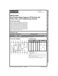
CONCERNING THE STICKER DISPLAY<br />
CONCERNING WARNING DISPLAYS<br />
SEGA product has Stickers describing the product<br />
manufacture No. (Serial No.) and Electrical<br />
Specifications. Also it has a Sticker describing where to<br />
contact for repair and for purchasing parts.<br />
When inquiring about or asking for repair, mention<br />
the Serial No. and Name of Machine indicated on the<br />
Sticker. The Serial No. indicates the product register.<br />
Identical machines could have different parts depending<br />
on the date of production. Also, improvements<br />
and modifications might have been made after the<br />
publication of this Manual. In order to meet the above<br />
situations, mention the Serial No. when contacting the<br />
applicable places.<br />
SEGA product has <strong>warning</strong> displays on Stickers, Labels<br />
and or printed instructions adhered / attached to or<br />
incorporated in the places where a potentially hazardous<br />
situation can arise. The <strong>warning</strong> displays are intended<br />
for accident prevention for the customers and for<br />
avoiding hazardous situation relating to maintenance<br />
and servicing work. There are some portions in the<br />
Cabinet, which are subject to high tension voltage, etc.<br />
where accidents can be caused merely by touching.<br />
When performing the servicing work , be very careful<br />
of the <strong>warning</strong> displays. Especially, any complex repair<br />
and replacement work not mentioned herein, should<br />
be performed by those technical personnel who have<br />
knowledge of electricity and technical expertise.<br />
For the prevention of accidents, caution any customer<br />
whose act runs counter to the <strong>warning</strong>s, as to the effect<br />
that he must stop the act.<br />
440-WS0141-EG<br />
440-WS0142-EG<br />
440-CS0186-EG<br />
440-DS0013XEG<br />
440-WS0002XEG<br />
Electrical Specifications Display<br />
Serial No. Display<br />
* NOTE: ILLUSTRATIONS MAY DIFFER FROM ACTUAL PRODUCT
1. HANDLING PRECAUTIONS<br />
When installing or inspecting the machine, be very careful of the following points and pay attention<br />
to ensure that the player can enjoy the game safely.<br />
Non-compliance with the following points or inappropriate handling running counter to the cautionary<br />
matters herein stated can cause personal injury or damage to the machine.<br />
WARNING!<br />
Before performing work, be sure to turn power off. Performing the work<br />
without turning power off can cause an electric shock or short circuit. In the<br />
case work should be performed in the status of power on, this manual always<br />
states to that effect.<br />
To avoid electric shock or short circuit, do not plug in or unplug quickly.<br />
To avoid electric shock, do not plug in or unplug with a wet hand.<br />
Do not expose Power Cords and Earth Wires on the surface, (floor, passage,<br />
etc.). If exposed, the Power Cords and Earth Wires are susceptible to damage.<br />
Damaged cords and wires can cause electric shock or short circuit.<br />
To avoid causing a fire or electric shock, do not put things on or damage<br />
Power Cords.<br />
When or after installing the product, do not unnecessarily pull the power cord.<br />
If damaged, the power cord can cause a fire or electric shock.<br />
In case the power cord is damaged, ask for replacement through where the<br />
product was purchased from or the office herein stated. Using the cord as is<br />
damaged can cause fire, electric shock or leakage.<br />
Be sure to perform grounding appropriately. Inappropriate grounding can<br />
cause an electric shock.<br />
Be sure to use fuses meeting specified rating. Using fuses exceeding the<br />
specified rating can cause a fire or electric shock.<br />
Completely make connector connections for IC BD and others. Insufficient<br />
insertion can cause an electric shock.<br />
Specification changes, removal of equipment, conversion and/or addition, not<br />
designated by SEGA are not permitted.<br />
• Failure to observe this may cause a fire or an electric shock. Non-compliance<br />
with this instruction can have a bad influence upon physical conditions of the<br />
players or the lookers-on, or result in injury during play.<br />
• SEGA shall not be held responsible for damage, compensation for damage to<br />
a third party, caused by specification changes not designated by SEGA.<br />
Be sure to perform periodic maintenance inspections herein stated.<br />
1 www.seuservice.com
STOP<br />
IMPORTANT!<br />
For the IC board circuit inspections, only the logic tester is allowed. The use<br />
of a multiple-purpose tester is not permitted, so be careful in this regard.<br />
The Projector is employed for this machine. The Projector's screen is<br />
susceptible to damage, therefore, be very careful when cleaning the screen.<br />
For details, refer to PROJECTOR.<br />
Static electricity from your body may damage some electronics devices on the<br />
IC board. Before handling the IC board, touch a grounded metallic surface so<br />
that the static electricity can be discharged.<br />
Some parts are the ones designed and manufactured not specifically for<br />
this game machine. The manufacturers may discontinue, or change the<br />
specifications of, such general-purpose parts. If this is the case, Sega cannot<br />
repair or replace a failed game machine whether or not a warranty period has<br />
expired.<br />
PRODUCTION DATE <br />
This SEGA product was produced in the year of:<br />
2002<br />
This signifies that this work was disclosed in 2002.<br />
www.seuservice.com<br />
2
2. PRECAUTIONS CONCERNING INSTALLATION LOCATION<br />
WARNING!<br />
This product is an indoor game machine. Do not install it outside. Even indoors,<br />
avoid installing in places mentioned below so as not to cause a fire, electric shock,<br />
injury and or malfunctioning.<br />
Places subject to rain or water leakage, or places subject to high humidity in<br />
the proximity of an indoor swimming pool and or shower, etc.<br />
Places subject to direct sunlight, or places subject to high temperatures in the<br />
proximity of heating units, etc.<br />
Places filled with inflammable gas or vicinity of highly inflammable/volatile<br />
chemicals or hazardous matter.<br />
Dusty places.<br />
Sloped surfaces.<br />
Places subject to any type of violent impact.<br />
Vicinity of anti-disaster facilities such as fire exits and fire extinguishers.<br />
The operating (ambient) temperature range is from 5ºC to 30ºC.<br />
LIMITATIONS OF USAGE REQUIREMENTS<br />
WARNING!<br />
Be sure to check the Electrical Specifications.<br />
Ensure that this product is compatible with the location's power supply, voltage<br />
and frequency requirements.<br />
A plate describing Electrical Specifications is attached to the product.<br />
Non-compliance with the Electrical Specifications can cause a fire and electric<br />
shock.<br />
This product requires the Breaker and Earth Mechanisms as part of the location<br />
facilities. Using them in a manner not independent can cause a fire and<br />
electric shock.<br />
Ensure that the indoor wiring for the power supply is rated at 10 A or higher<br />
(AC single phase 100 ~ 120 V area). Non-compliance with the Electrical<br />
Specifications can cause a fire and electric shock.<br />
Be sure to independently use the power supply equipped with the Earth Leakage<br />
Breaker. Using a power supply without the Earth Leakage Breaker can<br />
cause an outbreak of fire when earth leakage occurs.<br />
Putting many loads on one electrical outlet can cause generation of heat and a<br />
fire resulting from overload.<br />
When using an extension cord, ensure that the cord is rated at 10 A or higher<br />
(AC 100 ~ 120 V area). Using a cord rated lower than the specified rating can<br />
cause a fire and electric shock.<br />
3 www.seuservice.com
Operation Area<br />
WARNING!<br />
For the operation of this machine, secure a minimum area of 74.3 in.<br />
(W)×73 in. (D). In order to prevent injury resulting from the falling down<br />
accident during game play, be sure to secure the minimum area for operation.<br />
Be sure to provide sufficient space so as to allow this product's ventilation<br />
fan to function efficiently. To avoid machine malfunctioning and a fire, do<br />
not place any obstacles near the ventilation opening.<br />
SEGA shall not be held responsible for damage, compensation for damage<br />
to a third party, resulting from the failure to observe this instruction.<br />
STOP<br />
IMPORTANT!<br />
For transporting the machine into the location's building, the minimum necessary<br />
dimensions of the opening (of doors, etc.) are 40 in. (W) and<br />
67 in. (H).<br />
Electric current consumption<br />
MAX. 10 A (AC 120 V 60 Hz)<br />
FIG. 2<br />
www.seuservice.com<br />
4
3. OPERATION<br />
PRECAUTIONS TO BE HEEDED BEFORE STARTING THE OPERATION<br />
To avoid injury and trouble, be sure to constantly give careful attention to the behavior and manner<br />
of the visitors and players.<br />
WARNING!<br />
In order to avoid accidents, check the following before starting the operation:<br />
To ensure maximum safety for the players and the customers, ensure that<br />
where the product is operated has sufficient lighting to allow any <strong>warning</strong>s<br />
to be read. Operation under insufficient lighting can cause bodily contact<br />
with each other, hitting accident, and or trouble between customers.<br />
Be sure to perform appropriate adjustment of the monitor (projector). For<br />
operation of this machine, do not leave monitor's flickering or deviation as<br />
is. Failure to observe this can have a bad influence upon the players' or the<br />
customers' physical conditions.<br />
It is suggested to ensure a space allowing the players who feel sick while<br />
playing the game to take a rest.<br />
Check if all of the adjusters are in contact with the surface. If they are not,<br />
the Cabinet can move and cause an accident.<br />
Ensure that all of the Adjusters are in contact<br />
with the floor.<br />
5 www.seuservice.com
WARNING!<br />
Do not put any heavy item on this product. Placing any heavy item on the<br />
product can cause a falling down accident or parts damage.<br />
Do not climb on the product. Climbing on the product can cause falling down<br />
accidents. To check the top portion of the product, use a step.<br />
To avoid electric shock, check to see if door & cover parts are damaged or<br />
omitted.<br />
To avoid electric shock, short circuit and or parts damage, do not put the following<br />
items on or in the periphery of the product.<br />
Flower vases, flowerpots, cups, water tanks, cosmetics, and receptacles/<br />
containers/vessels containing chemicals and water.<br />
CAUTION!<br />
To avoid injury, be sure to provide sufficient space by considering the potentially<br />
crowded situation at the installation location. Insufficient installation<br />
space can cause making bodily contact with each other, hitting accidents, and or<br />
trouble between customers.<br />
PRECAUTIONS TO BE HEEDED DURING OPERATION (PAYING ATTENTION TO CUSTOMERS)<br />
To avoid injury and trouble, be sure to constantly give careful attention to the behavior and manner<br />
of the visitors and players.<br />
WARNING!<br />
To avoid injury and accidents, those who fall under the following categories<br />
are not allowed to play the game.<br />
• Those who need assistance such as the use of an apparatus when walking.<br />
• Those who have high blood pressure or a heart problem.<br />
• Those who have experienced muscle convulsion or loss of consciousness when<br />
playing video game, etc.<br />
• Those who have a trouble in the neck and or spinal cord.<br />
• Intoxicated persons.<br />
• Pregnant women or those who are in the likelihood of pregnancy.<br />
• Persons susceptible to motion sickness.<br />
• Persons whose act runs counter to the product's <strong>warning</strong> displays.<br />
A player who has never been adversely affected by light stimulus might experience<br />
dizziness or headache depending on his physical condition when playing<br />
the game. Especially, small children can be subject to those conditions.<br />
Caution guardians of small children to keep watch on their children during<br />
play.<br />
Instruct those who feel sick during play to have a medical examination.<br />
To avoid injury resulting from falling down and electric shock due to spilled<br />
drinks, instruct the player not to place heavy items or drinks on the product.<br />
To avoid electric shock and short circuit, do not allow customers to put hands<br />
and fingers or extraneous matter in the openings of the product or small openings<br />
in or around the doors.<br />
To avoid falling down and injury resulting from falling down, immediately<br />
stop the customer's leaning against or climbing on the product, etc.<br />
www.seuservice.com<br />
6
WARNING!<br />
To avoid electric shock and short circuit, do not allow the customers to unplug<br />
the power plug without a justifiable reason.<br />
This product is intended for 1 Player only per seat. Playing the game by 2 or<br />
more Players riding on the seat together can cause falling down and collision<br />
accidents by striking head, hand, or elbow.<br />
Caution lookers-on so as not to<br />
touch the operating unit while<br />
in play. Failure to observe this<br />
may cause bodily contact with<br />
the player and trouble between<br />
the customers.<br />
Caution the player so as not to<br />
hold a child in her/his lap to<br />
play. Failure to observe this<br />
may cause the child to be<br />
caught between the Control<br />
Panel and the player and fall<br />
down.<br />
CAUTION!<br />
Immediately stop such violent acts as hitting and kicking the product. Such<br />
violent acts can cause parts damage or falling down, resulting in injury due to<br />
fragments and falling down.<br />
Instruct the Player to adjust the seat before playing the game. Playing the<br />
game in a forcible posture can cause a contingent accident.<br />
7 www.seuservice.com
PRECAUTIONS TO BE HEEDED BEFORE STARTING THE OPERATION (CARD SYSTEM)<br />
STOP<br />
IMPORTANT!<br />
When an unjust act is performed, no written data is backed up mechanically.<br />
The following acts may be judged to be unjust acts.<br />
Since it also becomes a defect of operation and the cause of parts damage, caution<br />
the player not to perform the following acts.<br />
•Use of cards bent or deformed<br />
•Use of cards adhered seals or extraneous matter on<br />
•Use of a card mixed two sheets<br />
•Use of cards other than dedicated cards<br />
•When a card is extracted quickly<br />
If the card reader/writer has not been set as being unused, you will be unable to select any game<br />
mode with use of cards while the game will be in progress.<br />
Thus, for the card reader/writer, deal with the player, paying attention to the following points:<br />
Even if the player requests the system for use of cards when you have set the machine so that<br />
the card reader/writer is not used, the request is rejected.<br />
WARNING!<br />
WARNING: HAZARD TO EPILEPTICS.<br />
A very small portion of the population has a condition which may cause them<br />
to experience epileptic seizures or have momentary loss of consciousness when<br />
viewing certain kinds of flashing lights or patterns that are present in our daily<br />
environment. These persons may experience seizures while watching some<br />
kinds of television pictures or playing certain video games. People who have<br />
not had any previous seizures may nonetheless have an undetected epileptic<br />
condition.<br />
If you or anyone in your family has experienced symptoms linked to an epileptic<br />
condition (e.g., seizures or loss of awareness), immediately consult your<br />
physician before using any video games.<br />
We recommend that parents observe their children while they play video<br />
games. If you or your child experience the following symptoms: dizziness,<br />
altered vision, eye or muscle twitching, involuntary movements, loss of awareness,<br />
disorientation, or convulsions, DISCONTINUE USE IMMEDIATELY<br />
and consult your physician.<br />
www.seuservice.com<br />
8
4. NAME OF PARTS<br />
FIG. 4 a OVERVIEW<br />
FIG. 4 b REAR VIEW<br />
TABLE 4 Dimensions and Weights<br />
Width x Length x Height Weight<br />
CABINET 1 44 in x 68 in x 71.75 in 865 LB<br />
CABINET 2 36.75 in x 68 in x 71.75 in 700 LB<br />
ASSY POP 30 in x 22 in x 14 in 1 LB<br />
When assembled 80.75 in x 68 in x 71.75 in 1565 LB<br />
9 www.seuservice.com
5. ACCESSORIES<br />
When transporting the machine, make sure that the following parts are supplied.<br />
Magnetic cards for the recording of play results, and cleaning kits for cleaning the head of the card<br />
reader/writer are sold separately. Subsequent purchases of these items can be made by contacting<br />
the office listed on this Owner's Manual or the dealer from whom the product was originally purchased.<br />
Be sure to provide the part number(s), name(s), and required number of items.<br />
Cleaning Kit<br />
601-11050 CLEANING CARD: Package of 30 sheets<br />
Magnetic Cards<br />
601-11136-01 CARD PACKAGE TOF ENG: Package of 200 Magnetic Cards<br />
TABLE 5 a ACCESSORIES<br />
DESCRIPTION OWNER'S MANUAL<br />
Part No. (Qty.) 999-1488<br />
Notes<br />
Figures<br />
Parts not labeled with part numbers are as yet<br />
unregistered or cannot be registered. Be sure to<br />
handle all parts with care, as some parts are not<br />
available for purchase separately.<br />
NAOMI NETWAORK SYSTEM SERVICE<br />
MANUAL<br />
420-6660-01 (1)<br />
Instruction Manual for the Game Board<br />
CLEANING CARD<br />
601-11050 (1)<br />
For the periodic maintenance. See Sections 7 and 10.<br />
(30 sheets of Cleaning Card)<br />
KEY MASTER<br />
9301A (2)<br />
For opening/closing<br />
the doors<br />
KEY<br />
(2)<br />
TAMPERPROOF<br />
WRENCH<br />
T-27 Torx 1/4-20 (1)<br />
T-25 Torx 10/32 (1)<br />
T-20 Torx M4 (1)<br />
T-15 Torx 8/32 (1)<br />
Tool<br />
For the CASHBOX DOOR<br />
The Keys are inside the Coin<br />
Chute Door at the time of shipment<br />
from the factory.<br />
CARTON BOX<br />
601-11044 (1)<br />
Used for transporting the Game Board. See Fig. 5a.<br />
CARD PACKAGE TOF ENG<br />
601-11136-01 (6)<br />
Cards for card reader/writer<br />
*Picture not available at this time.<br />
www.seuservice.com<br />
10
The following Table 5b lists the parts that are separately marketed but are necessary when<br />
booting this product's software. When having unpacked the shipping crate, make sure that all the<br />
parts in this Table 5b are in the crate. If not so, contact where you have obtained the product.<br />
TABLE 5 b (XKT-0833 : GD-ROM DRIVE KIT)<br />
GD-ROM DRIVE<br />
XKT-0833<br />
Device that loads the software in a GD-ROM disc.<br />
see 5 of Section 6.<br />
GD-ROM DRIVE CARTON BOX<br />
(1)<br />
Used for transporting the GD-ROM DRIVE.<br />
See FIG. 5 b.<br />
This carton box is a standard accessory of the<br />
GD-ROM drive.<br />
TABLE 5 c (XKT-1208-G-EX1 : GD-ROM KIT TOF ENG EXP)<br />
GD ROM KIT TOF<br />
KEY CHIP (1)<br />
See 3 of Section 6.<br />
CUSHION SPONGE<br />
601-11137 (1)<br />
GD-ROM Disc Protector<br />
STICKER<br />
442-00108B (1)<br />
Shield Case Sticker<br />
840-0108B<br />
NAOMI2 GDROM TOF ENG<br />
(1)<br />
See 3 of Section 6.<br />
NOTE: When you order the GD-ROM disc only, specify the part<br />
number 610-0625-0025 (GD SOFT TOF ENG).<br />
11 www.seuservice.com
HOW TO USE THE CARTON BOX (GD-ROM DRIVE)<br />
STOP<br />
IMPORTANT!<br />
When you want to order for replacing or repairing service of the GD-ROM<br />
drive that is used by the product, pack it in a carton box as instructed below,<br />
and then deliver the carton box to a service agent. If you do not observe the<br />
instruction, your order may not be accepted or may be charged additionally. If<br />
you handle the GD-ROM drive differently from the following instructions, its<br />
components may be damaged.<br />
• Contain the GD-ROM drive in a dedicated carton box. Do not disassemble<br />
it or remove any part from it unless otherwise instructed.<br />
• Before containing the GD-ROM drive in a dedicated carton box, attach the<br />
GD-ROM drive lid (DISC LID) onto the drive and fix the lid with a screw.<br />
• Before containing the GD-ROM drive in a dedicated carton box, remove<br />
the GD-ROM disk from the drive. Do not attempt to move the GD-ROM<br />
drive with a GD-ROM disk inside.<br />
• Before containing the GD-ROM drive in a dedicated carton box, remove<br />
the GD-ROM drive bracket. Carefully keep the GD-ROM drive bracket<br />
and the 4 set screws, because they will be reused.<br />
• When inserting the GD-ROM drive into a dedicated carton box, be careful<br />
about an inserting direction as illustrated below.<br />
• The packing materials in a carton box are used as a cushion. Use them<br />
always when inserting the GD-ROM drive into a dedicated carton box. Do<br />
not bend them.<br />
Remove the GD drive bracket.<br />
FIG. 5 b<br />
www.seuservice.com<br />
12
6. ASSEMBLING AND INSTALLATION<br />
WARNING!<br />
Perform assembly work by following the procedure herein stated. Failing to<br />
comply with the instructions can cause electric shock hazard.<br />
Perform assembling as per this manual. Since this is a complex machine,<br />
erroneous assembling can cause an electric shock, machine damage and or not<br />
functioning as per specified performance.<br />
When assembling, be sure to use plural persons. Depending on the assembly<br />
work, there are some cases in which working by one person alone can cause<br />
personal injury or parts damage.<br />
Ensure that connectors are accurately connected. Incomplete connections can<br />
cause electric shock hazard.<br />
Be careful not to damage the wires. Damaged wires may cause electric shock<br />
or short circuit or present a fire risk.<br />
This work should be performed by the Location's Maintenance Man or<br />
Serviceman. Performing work by non-technical personnel can cause a severe<br />
accident such as electric shock. Failing to comply with this instruction can<br />
cause a severe accident such as electric shock to the player during operation.<br />
Provide sufficient space so that assembling can be performed. Performing<br />
work in places with narrow space or low ceiling may cause an accident and<br />
assembly work to be difficult.<br />
To perform work safely and avoid serious accident such as the cabinet's<br />
falling down, do not perform work in places where step-like grade differences,<br />
a ditch, or slope exist.<br />
CAUTION!<br />
Handle molded parts with care. Undue weight or pressure may cause them to<br />
break and the broken pieces may cause injury.<br />
To perform work safely and securely, be sure to prepare a step which is in<br />
a secure and stable condition. Performing work without using the step can<br />
cause violent falling down accidents.<br />
Make sure that the GD cable connector is inserted parallel to the plug.<br />
Improper insertion may cause damage to the connector and present a fire<br />
When carrying out the assembling and installation, follow the following 6-item sequence.<br />
1<br />
2<br />
3<br />
4<br />
5<br />
6<br />
INSTALLING THE POP AND THE POP CARD<br />
SECURING IN PLACE(ADJUSTER ADJUSTMENT)<br />
INSTALLING THE GD-ROM DRIVE(SETTING GD-ROM DISC)<br />
POWER SUPPLY, AND EARTH CONNECTION<br />
TURNING POWER ON<br />
ASSEMBLING CHECK<br />
13 www.seuservice.com
Tools such as a Phillips type screwdriver, wrench, socket wrench and Ratchet Handle are<br />
required for the assembly work.<br />
WRENCH<br />
24mm<br />
1<br />
Phillips type screwdriver<br />
INSTALLING THE POP AND POP CARD<br />
Install the POP Holder on the top<br />
of the Billboard by using the 4<br />
screws. For performing this work,<br />
be sure to prepare a step.<br />
POP HOLDER<br />
SOCKET WRENCH,RATCHET HANDLE<br />
SCREW (4)<br />
M6×16,w/flat and spring washers<br />
PHOTO 6. 1 a<br />
For performing work, prepare a step.<br />
* Note: Picture may differ from actual unit.<br />
www.seuservice.com<br />
14
Attach the POP to the POP Holder.<br />
Slide the POP cut-out so that the edges fit into<br />
the protruding portions of the POP Holder.<br />
POP<br />
POP CUT-OUT<br />
PHOTO 6. 1 b<br />
Attach Billboard Sash R with 2 Truss screws.<br />
Use 2 Truss screws to attach Billboard Sash L<br />
to the opposite side in the same manner.<br />
TRUSS SCREW (2)<br />
chrome<br />
BILLBOARD SASH R<br />
PHOTO 6. 1 c<br />
15 www.seuservice.com
2<br />
SECURING IN PLACE (ADJUSTER ADJUSTMENT)<br />
WARNING!<br />
Make sure that all of the adjusters are in contact with the floor. If they are not, the<br />
cabinet can move and cause an accident.<br />
This product has 8 casters and 8 Adjusters. (FIG. 6. 2 a) When the installation position is<br />
determined, cause the adjusters to come into contact with the floor directly, make adjustments<br />
in a manner so that the casters will be raised approximately 5 mm from the floor and make sure<br />
that the machine position is level.<br />
Transport the product to the<br />
installation position.<br />
Have all of the Adjusters make contact<br />
with the floor. Adjust the Adjuster's<br />
height by using a wrench so that the<br />
machine position is kept level.<br />
After making adjustment, fasten the<br />
Adjuster Nut upward and secure the<br />
height of Adjuster.<br />
FIG. 6. 2 a BOTTOM VIEW<br />
* Note:Picture may differ from actual unit.<br />
FIG. 6. 2 b ADJUSTER<br />
www.seuservice.com<br />
16
FIG. 6. 2 e<br />
Provide ventilation space for the ventilation<br />
opening.<br />
Allow more than 28 in. of space for customer<br />
traffic.<br />
17 www.seuservice.com
3<br />
INSTALLING THE GD-ROM DRIVE (SETTING GD-ROM DISC)<br />
STOP<br />
IMPORTANT!<br />
Carefully handle the GD-ROM drive so as not to contaminate the disc and the<br />
readout lens with stains and dust particles.<br />
Do not continue to use the scratched GD-ROM disc. The scratched GD-ROM<br />
disc may cause the system to malfunction.<br />
Set the GD-ROM disc onto the GD-ROM drive with its labeled side facing<br />
upward.<br />
The key chip is a precision device. Handle it carefully and avoid exposure to<br />
heat, shock and static electricity, as these may cause damage to the device.<br />
The key chip is contained in the GD-ROM disc case. Always use them as a<br />
set.<br />
Unpack the shipping crate, and take out the GD-ROM drive, GD-ROM drive bracket, and GD-<br />
ROM disc.<br />
GD DRIVE BRACKET<br />
PHOTO 6. 3 a<br />
GD-ROM DRIVE<br />
Use the 4 tapping screws to fix the GD-ROM drive bracket onto the GD-ROM drive. Be careful<br />
about a fixing direction.<br />
TAPPING SCREW (4)<br />
M4×8<br />
GD DRIVE BRACKET<br />
FIG. 6. 3 b<br />
GD-ROM DRIVE<br />
CAUTION for U. S. A., Europe, and Australia:<br />
Attach the 2 caution stickers for a laser ray onto<br />
the GD-ROM drive.<br />
FIG. 6. 3 a<br />
www.seuservice.com<br />
18
Remove the 1 truss head screw that<br />
fixes the GD-ROM drive lid (DISC<br />
LID). And turn clockwise the lid to<br />
remove.<br />
TRUSS SCREW (1)<br />
M3×8<br />
PHOTO 6. 3 b<br />
Set the GD-ROM disc onto the GD-ROM drive with its labeled side facing upward.<br />
Return the lid to its original place, and fix it with 1 truss head screw. Be careful not to fasten the<br />
screw too tightly.<br />
PHOTO 6. 3 c<br />
TRUSS SCREW (1)<br />
M3×8<br />
19 www.seuservice.com
Undo the lock on the side of the unit base and remove the Truss screws.<br />
Turn the knob to open the lock, and lower the seat towards the backrest. Slowly lower the<br />
backrest until it touches the floor to prevent damage to the seat components. Put a drop cloth on<br />
the floor to prevent damaging the surface of the seat components.<br />
UNLOCK<br />
DROP CLOTH TO PREVENT DAMAGE<br />
TO SURFACE OF PARTS<br />
TRUSS SCREW (2),<br />
black<br />
FIG. 6. 3 b<br />
* Note Figure may appear different then actual product.<br />
Attach the GD-ROM drive with 3 screws.<br />
SCREW (3) M4×16,<br />
w/flat & spring washers<br />
PHOTO 6. 3 d<br />
www.seuservice.com<br />
20
Connect the GD cable connector (for data communication) to the DIMM board.<br />
GD CABLE CONNECTOR<br />
PHOTO 6. 3 e<br />
Insert both the GD cable connector (for data communication) and the power cord connector into<br />
the GD-ROM drive. Be careful about an inserting direction in this instance. Make sure that the<br />
connectors are inserted firmly and completely. Secure the cable with the cord clamp.<br />
GD-ROM DRIVE<br />
GD Cable connector<br />
Power Cord connector<br />
Secure the cable.<br />
PHOTO 6. 3 f<br />
21 www.seuservice.com
Paying attention to the direction of the<br />
Key Chip, insert it securely into the<br />
NAOMI DIMM Board Case.<br />
KEY CHIP<br />
Place the Sticker (442-00108B) on<br />
the side of the DIMM Board Case as<br />
shown in the figure.<br />
KEY CHIP<br />
PROJECTION<br />
STICKER(442-00108B)<br />
Sticker Position<br />
FIG. 6. 3 c<br />
www.seuservice.com<br />
22
4<br />
POWER SUPPLY, AND EARTH CONNECTION<br />
WARNING!<br />
Be sure to independently use the power supply socket outlet equipped with<br />
an Earth Leakage Breaker. Using a power supply without an Earth Leakage<br />
Breaker can cause a fire when electric leakage occurs.<br />
Ensure that the "accurately grounded indoor earth terminal" and the earth<br />
wire cable are available (except in the case where a power cord plug with<br />
earth is used). This product is equipped with the earth terminal. Connect the<br />
earth terminal and the indoor earth terminal with the prepared cable. If the<br />
grounding work is not performed appropriately, customers can be subjected to<br />
an electric shock, and the product's functioning may not be stable.<br />
Ensure that the power cord and earth wire are not exposed on the surface<br />
(passage, etc.). If exposed, they can be caught and are susceptible to damage.<br />
If damaged, the cord and wire can cause electric shock and short circuit<br />
accidents. Ensure that the wiring position is not in the customer's passage<br />
way or the wiring has protective covering.<br />
After wiring power cord on the floor, be sure to protect the power cord.<br />
Exposed power cord is susceptible to damage and causes an electric shock<br />
accident.<br />
The AC Unit is located on one side of Cabinet. The AC Unit has Main SW, Earth Terminal and<br />
the Inlet which connects the Power Cord.<br />
Ensure that the Main SW is OFF.<br />
MAIN SW<br />
Main SW off<br />
INLET<br />
FIG. 6. 4 a AC unit<br />
* Note: Actual Power Supply connection<br />
may vary from photo<br />
AC Cable (Power Cord)<br />
23 www.seuservice.com
5<br />
TURNING POWER ON<br />
Turn on the AC unit's main switch to supply power to the unit. Once power is turned on, the<br />
fluorescent lamp lights up. The Start System Screen displays after a lapse of several seconds.<br />
It is followed by the screen that indicates that the network is currently being checked if the<br />
communication mode has been set. If there is a bad or improper communication connection, each<br />
screen will not proceed to the next, remaining on the currently Network Check Screen. If this<br />
occurs, resolve the error according to the instructions in this document.<br />
If the communication mode has not been set or the communication check ends normally, the<br />
Motor Check Screen returns. While the Motor Check Screen is on-screen, the steering wheel can<br />
move either clockwise or counterclockwise. If you touch the wheel, the motor check is hindered<br />
and the game will not operate normally. So, you must not touch it at this time. Failures are<br />
displayed, if found. Resolve the errors according to the instructions in this document.<br />
Once all the above steps have been completed, the Advertise Screen displays and voices are<br />
output through the left and right loudspeakers, unless you have set the machine so that no voices<br />
are output during the Advertise mode.<br />
This product retains the number of credits and the ranking data even after the power is turned off.<br />
It does not retain data about the fractional number of coins (i.e., the number of coins not reaching<br />
one credit) or the bonus adder count.<br />
* Note: Picture may differ from actual unit.<br />
FIG. 6. 5<br />
Note: The first time the power is turned on, the unit will automatically enter Cleaning Mode.<br />
Follow the on-screen instructions to carry out cleaning of the unit.<br />
www.seuservice.com<br />
24
Network Check Screen<br />
Each Check Screen is followed as below.<br />
CHECKING NETWORK NOW<br />
Card Reader/Writer Check Screen<br />
When Card is left in the Card Reader/Writer;<br />
CARD R/W INITIALIZE...<br />
PLEASE GET CARD<br />
Motor Check Screen<br />
Remove the card. Screen does not change until the<br />
card is removed.<br />
KICKBACK INITIALIZE...<br />
When cleaning is required;<br />
PLEASE INSERT CLEANING CARD.<br />
Steering wheel will turn. Do not touch it.<br />
Insert the cleaning card. (See 7-2 HEAD CLEANING.)<br />
25 www.seuservice.com
6<br />
ASSEMBLING CHECK<br />
In the TEST MODE, ascertain that the assembly has been made correctly and IC BD. is<br />
satisfactory (refer to Section 10).<br />
In the test mode, perform the following test:<br />
(1)MEMORY TEST<br />
Selecting the RAM TEST on the system test mode menu screen causes the on-board memory to<br />
be tested automatically. The game board is satisfactory if the display beside each IC No. shows<br />
GOOD.<br />
RAM TEST<br />
IC29 GOOD<br />
IC35 GOOD<br />
IC09 GOOD IC10 GOOD<br />
IC11 GOOD IC12 GOOD<br />
IC16 GOOD IC18 GOOD<br />
IC20 GOOD IC22 GOOD<br />
IC17 GOOD IC19 GOOD<br />
IC21 GOOD IC23 GOOD<br />
IC106 GOOD IC107 GOOD<br />
IC108 GOOD IC109 GOOD<br />
IC111 GOOD IC113 GOOD<br />
IC115 GOOD IC117 GOOD<br />
IC112 GOOD IC114 GOOD<br />
IC116 GOOD IC118 GOOD<br />
PRESS TEST BUTTON TO EXIT<br />
DIMM BOARD TEST<br />
PROGRAM VER : ***<br />
DIMM SLOT 0 : GOOD<br />
DIMM SLOT 1 : GOOD<br />
DIMM STATUS : GOOD<br />
CHECKING DIMM BD<br />
DIMM0 - GOOD<br />
DIMM1 - GOOD<br />
IC34,35S - GOOD<br />
IC10,11S - GOOD<br />
GD DRIVE - GOOD<br />
--- COMPLETED ---<br />
PRESS TEST BUTTON TO EXIT<br />
www.seuservice.com<br />
26
(2)SOUND TEST<br />
SOUND TEST<br />
RIGHT SPEAKER OFF<br />
LEFT SPEAKER OFF<br />
-> EXIT<br />
In the system test mode, selecting SOUND<br />
TEST causes the screen (on which sound<br />
related BD and wiring connections are<br />
tested) to be displayed.<br />
Check if the sound is satisfactorily emitted<br />
from each speaker and the sound volume is<br />
appropriate.<br />
SELECT WITH SERVICE BUTTON<br />
AND PRESS TEST BUTTON<br />
(3)C.R.T. TEST<br />
In the system test mode menu, selecting C.R.T. TEST allows the screen (on which the monitor<br />
is tested) to be displayed. Although the monitor adjustments have been made at the time<br />
of shipment from the factory, color deviation, etc., may occur due to the effect caused by<br />
geomagnetism, the location building's steel frames and other game machines in the periphery.<br />
By watching the system test mode screen, make judgment as to whether an adjustment is<br />
needed. If it is necessary, adjust the monitor by referring to Chapter 15.<br />
SYSTEM TEST MODE<br />
C.R.T. TEST 1/2<br />
C.R.T. TEST 2/2<br />
1 32<br />
RED<br />
GREEN<br />
BLUE<br />
WHITE<br />
PRESS TEST BUTTON TO CONTINUE<br />
PRESS TEST BUTTON TO EXIT<br />
* Note: Screen shows a grid.<br />
27 www.seuservice.com
(4)INPUT TEST<br />
GAME TEST MODE<br />
INPUT TEST<br />
STEERING XXH<br />
ACCEL<br />
XXH<br />
BRAKE XXH<br />
GEAR POSITION N<br />
START<br />
OFF<br />
CHANGE VIEW OFF<br />
SERVICE OFF<br />
TEST<br />
OFF<br />
Selecting the INPUT TEST on the game test<br />
mode menu screen causes the screen (on<br />
which each switch is tested) to be displayed.<br />
Press each switch. If the display beside each<br />
switch indicates "ON," the switch and wiring<br />
connections are satisfactory.<br />
PRESS TEST AND SERVICE BUTTON<br />
TO EXIT<br />
(5)OUTPUT TEST<br />
GAME TEST MODE<br />
OUTPUT TEST<br />
->START BUTTON<br />
CHANGE VIEW BUTTON<br />
Select OUTPUT TEST from the Menu<br />
screen in the Game Test Mode to cause<br />
the screen (on which output unit such as<br />
lamps and wiring connections are tested) to<br />
appear. Ensure that the output unit functions<br />
satisfactorily.<br />
PRESS TEST BUTTON TO EXIT<br />
Perform the above inspections also at the time of monthly inspection.<br />
www.seuservice.com<br />
28
7. CARD READER/WRITER<br />
7-1 SETTING DEDICATED CARDS<br />
STOP<br />
IMPORTANT!<br />
Be sure to use dedicated cards available for this product.<br />
Use of ones other than such dedicated cards may cause a malfunction or<br />
failure of the machine.<br />
Be sure to set the specified number of card in the specified orientation by<br />
using the specified procedure. Wrong setting of the cards may cause the<br />
machine to fail.<br />
This machine allows you to set up to 100 cards at a time. You must not set<br />
over 101 cards at a time. If you do so, a trouble such as card jamming may<br />
occur.<br />
Set virgin cards taken out from a container that was unpacked immediately<br />
before use.<br />
Use of any deformed or deteriorated card may cause a trouble.<br />
Do not include a corrugated, bent, or used card in the card deck.<br />
When the unit is out of cards, a message will be displayed at the upper right of the screen during<br />
advertisements. Follow the instructions below to restock the system with cards. Cards may be<br />
stocked when the unit is on or off.<br />
After restocking the system with cards, the message displayed after the "SEGA" logo will be<br />
updated. Gameplay can be resumed without waiting for the updated message.<br />
Unlock and open the cover to find the card reader/writer.<br />
The dispenser on which you should place the cards is located at the rear of the reader/writer.<br />
From the card reader/writer, take out the dispenser upward in a straight line.<br />
UNLOCK<br />
DISPENSER<br />
PHOTO 7. 1<br />
* Note: Pictures may differ from actual Unit.<br />
29 www.seuservice.com
Remove the cover from the back of the dispenser.<br />
FIG. 7. 1 a<br />
Place the cards into the dispenser according to the instructions on the sticker annexed to the<br />
dispenser. Refer to the diagram shown on the sticker attached to the Dispenser and insert the<br />
cards into the Dispenser. Be careful not to insert the cards in the wrong direction or with the<br />
wrong side facing up.<br />
The Dispenser can only hold 100 cards. Do not attempt to insert more than 100 cards. Too many<br />
cards may cause the Dispenser to jam or result in other problems.<br />
Insert magnetic cards into the Dispenser in complete packs of 100 or after carefully counting the<br />
number of cards (not to exceed 100).<br />
FIG. 7. 1 b<br />
Reinstall the cover to the dispenser.<br />
Insert the dispenser into the card reader/writer. The dispenser can be inserted only in the<br />
predetermined orientation.<br />
Close and lock the cover.<br />
Secure with the truss screw<br />
www.seuservice.com<br />
30
7-2 HEAD CLEANING<br />
STOP<br />
IMPORTANT!<br />
The unit enters Head Cleaning Mode when any of the following conditions<br />
are met:<br />
• At power-up if the Card Reader/Writer has operated 100 times or more<br />
• At power-up if the date has been updated<br />
• At boot time after performing Backup Data Clear<br />
Once the unit enters Head Cleaning Mode, follow the on-screen instructions<br />
and perform Head Cleaning. The unit will not exit Cleaning Mode (i.e. games<br />
may not be played) until head cleaning is complete.<br />
Always use the designated Cleaning Card. Using anything other than the<br />
designated card or carrying out any other procedure other than the one<br />
outlined in the manual may cause faulty printing, faulty operation and/or unit<br />
failure.<br />
Cleaning Cards may only be used once. Dispose of them after use.<br />
Cleaning Cards should be used immediately after removal from the package.<br />
Cleaning Cards will not clean effectively if dried out.<br />
Perform head cleaning only when there are cards in the Card Reader/Writer<br />
Dispenser. If the Dispenser is empty, the part that secures the cards inside the<br />
Dispenser may touch the rotating part of the Card Reader/Writer and cause<br />
noise.<br />
Always remember to remove the Cleaning Card after completing head<br />
cleaning.<br />
After head cleaning, wait for the "SEGA LOGO" to be displayed at least<br />
twice before resuming gameplay.<br />
This machine records the number of times the Card Reader/Writer is used.<br />
The Card Reader/Writer writes data to and reads data from cards. Each write and read is counted,<br />
so the Card Reader/Writer usage count will not be the same as the number of times the game is<br />
played.<br />
Once head cleaning of the Card Reader/Writer is complete, the unit will exit this mode.<br />
Follow the on-screen instructions to carry out cleaning.<br />
CLEANING CARD<br />
PLEASE INSERT CLEANING CARD.<br />
Insert the Cleaning Card into the card slot.<br />
<br />
NOW CLEANING...<br />
Indicates that the unit is undergoing cleaning. Wait for cleaning<br />
to be completed.<br />
<br />
The unit exits to normal mode after cleaning is complete.<br />
Do not forget to remove the Cleaning Card.<br />
Wait for the "SEGA LOGO" to be displayed at least twice before<br />
resuming gameplay after cleaning.<br />
PHOTO 7. 2<br />
The Card Reader/Writer usage count described above is reset when cleaning is performed.<br />
*Note: Photo may differ from actual product.<br />
Manual head cleaning may also be performed from Test Mode. Refer to Test Mode for<br />
more details.<br />
31 www.seuservice.com
7-3 CLEARING CARD JAMS<br />
STOP<br />
IMPORTANT!<br />
When attempting to perform this operation without powering down so that<br />
gameplay can be restored, exercise extreme caution. Machine parts may move<br />
unexpectedly when the power is ON. This may result in fingers being caught or<br />
severed and other injuries.<br />
Verify the Stay Lock on the top cover before attempting this procedure. If the top<br />
cover closes during the procedure, it may result in serious injury.<br />
If a trouble such as card jamming occurs on the card reader/writer, you are notified of the<br />
trouble on the screen. You cannot proceed to a play unless you resolve the trouble at this time.<br />
First identify the trouble before you begin to take action.<br />
An error message is displayed at the top of the screen when cards become jammed. Use the<br />
RESTORE command (hold down the Start button + Change View button for a long time) to<br />
retry the function that caused the error.<br />
If repeated attempts continue to generate errors, follow the instructions below to remove the<br />
card. Removing the card may force the game to shut down. If the game shuts down, existing<br />
customer game data will not be saved.<br />
Unlock and open the cover.<br />
Unlock the hatch by drawing the<br />
green shaft attached to the top<br />
cover on the card reader/writer.<br />
While drawing the shaft, open the<br />
cover up.<br />
Remove the card jammed in the<br />
card reader/writer.<br />
While drawing<br />
the shaft, close the<br />
cover. With the<br />
top cover closed,<br />
release the green<br />
shaft. Check that<br />
the top cover has<br />
been locked securely.<br />
* Note: Unit may differ from Photo.<br />
Close and lock the cover.<br />
PHOTO 7. 3 b Remove the card jammed.<br />
www.seuservice.com<br />
32
8. PRECAUTIONS WHEN MOVING THE MACHINE<br />
WARNING!<br />
When moving the machine, be sure to unplug the power plug. Moving the<br />
machine with the plug as is inserted can damage the power cord and cause fire<br />
and electric shock hazards.<br />
When moving the machine on the floor, retract the Adjusters and ensure<br />
that Casters make contact with the floor. During transportation, pay careful<br />
attention so that Casters do not tread power cords and earth wires. Damaging<br />
the power cords can cause electric shock and short circuit hazards.<br />
Do not push the cabinet from the left/right when attempting to move the<br />
unit. Pushing from the sides may cause the unit to tip and result in injury and<br />
damage to parts.<br />
CAUTION!<br />
Do not push on any parts made of glass (e.g. CRT screen) or plastic, as these parts<br />
may break and result in bodily injury.<br />
Do not push the<br />
cabinet from the<br />
left/right direction.<br />
* Note: Pertains when unit is separated.<br />
FIG. 8 a<br />
33 www.seuservice.com
In locations with low ceilings,<br />
remove the POP and POP Holder<br />
before moving the machine.<br />
* Note: Machine may be different then illustrated.<br />
FIG. 8 b<br />
Place the machine on casters. .<br />
www.seuservice.com<br />
34
9. GAME DESCRIPTION<br />
The following explanations apply to the case the product is functioning satisfactorily. Should<br />
there be any moves different from the following contents, some sort of faults may have<br />
occurred. Immediately look into the cause of the fault and eliminate the cause thereof to ensure<br />
satisfactory operation.<br />
When the power is connected, the fluorescent lamp in the FL box is always on. When in an<br />
advertising state, the screen displays the demonstration pictures and ranking data. Sounds are<br />
heard from the speakers on the right and left of the monitor. The advertising sounds are not<br />
heard if you have set this function to off (disabled).<br />
The start button and the change view button on the control panel are integrated with a lamp. The<br />
start button (lamp) flashes when the coins are inserted enough to play the game.<br />
FIG. 9<br />
* Note: Unit in Photo may differ from actual Unit.<br />
35 www.seuservice.com
Game Overview<br />
The game is a car racing game with two different game modes: "Legend of the Streets" and<br />
"Time Attack". By connecting two units, you can also enjoy "Network Game" play. The card<br />
system allows players to store information such as the car, wins/loss records and car tune-up<br />
status on a special card.<br />
Legend of the Streets<br />
Game Content & Rules<br />
Battle rival characters man to man on 4 different courses. Each checkpoint you pass adds time to<br />
the overall time limit. The first one across the finish line with the allotted time wins. If you run<br />
out of time or cross the finish line second, you lose. Once you've defeated all 16 rival characters,<br />
you'll get a chance to race against a hidden rival character (final battle/race). Defeat him and<br />
you'll race for the title of street legend against the last hidden rival character (special battle/<br />
race). Only when the title is yours will you get to see the ending.<br />
INITIAL D CARD<br />
Purchasing a card when you start the game creates your car.<br />
The card can store all the data for one car. Information on the card<br />
includes the player name, car, tune-up status, names of defeated rival<br />
characters, times from Time Attack mode, Network Game records,<br />
passwords from Time Attack mode and more.<br />
The front of the card shows the driver (name), the car registered<br />
to that driver, the driver's home area (areas you've mastered) and a<br />
special 3 digit number, or KEY.<br />
Car Tune-Ups<br />
Depending on how well you do, points are added to your card when you use it to play in<br />
"Legend of the Streets" mode and "Time Attack" mode. When you've accumulated enough<br />
points, you are given the option of using those points to do tune-ups on your car to increase<br />
performance.<br />
www.seuservice.com<br />
36
Game Flow<br />
Insert Card Screen: Insert your<br />
card if you've got one after<br />
completing the Card Purchase<br />
Screens. If you don't already<br />
have a card, you can purchase<br />
one.<br />
Vehicle Selection Screen: This<br />
screen isn't displayed if you've<br />
already purchased a card.<br />
Transmission Selection Screen:<br />
This screen isn't displayed if<br />
you've already purchased a<br />
card.<br />
37 www.seuservice.com
If you're purchasing a card,<br />
select one of the Parts courses.<br />
These parts are then attached to<br />
your car when you accumulate<br />
enough points.<br />
If you're purchasing a card,<br />
enter your name (driver's name)<br />
at the player name input screen.<br />
Select "Legend of the Streets"<br />
at the Mode Selection Screen<br />
www.seuservice.com<br />
38
Course and rival character selection screens<br />
Rival Character Scenes<br />
Battle (Race)<br />
39 www.seuservice.com
Results Screen<br />
Tune Up Screen<br />
Use your card to play and<br />
accumulate points you can put<br />
towards performance enhancing<br />
tune-ups.<br />
Continue Screen<br />
Choose to continue or quit<br />
after rival character scenes. If<br />
you select "YES", nothing is<br />
recorded to the card and you<br />
can continue playing. If you<br />
select "NO", your game data is<br />
stored on your card and your<br />
game ends.<br />
www.seuservice.com<br />
40
Time Attack<br />
Game Content & Rules<br />
This is a race against time. The goal is to cross the finish line as quickly as you can. Each<br />
checkpoint you pass adds time to the overall time limit. When you cross the finish line, a<br />
password is displayed. You may use this password to participate in the online Internet rankings.<br />
In order to register the password, you must have played the game with a card and you'll need to<br />
enter the 3 digit number or KEY printed on the front of the card.<br />
After using the 60,000 points accumulated on the card, you can play Time Attack "Go Round<br />
All Courses". Courses are completed in the following order: Myogi (1 lap in a circular course<br />
that turns to the right), Usui (1 lap in a circular course that turns to the left), Akina (a downhill<br />
straight race) and Happogahara (straight race down and back).<br />
Your times, when recorded with the card (or tuned car), are displayed in the "TUNED" ranking.<br />
Your time, when not using a card, are displayed in the "NORMAL" ranking. The only way to<br />
accumulate points is to play with a card.<br />
Network Game<br />
Game Content & Rules<br />
This is a competitive race between two players. One of players' passage of the checkpoints adds<br />
the remaining times to both. The player that crosses the finish line first or the player in the lead<br />
when time runs out is declared the winner.<br />
You can use a card (tuned car) in Network Game. When playing with a card, your Network<br />
Game win/loss record is stored on the card. You cannot accumulate points in a Network Game.<br />
Game Over<br />
The Continue Screen is displayed at the end of each battle (race) in all game modes. If you<br />
choose not to continue, the game ends.<br />
Limit on Card Use<br />
After every 50 games with the same car, the game calls for a mandatory "Safety Check".<br />
Continued game play after each race is not counted as part of the 50 game limit. At each "Safety<br />
Check", you are given the option of renewing your card. Any data stored on your old card is<br />
copied over to a new card when you renew. You will not lose any points you accumulated on<br />
your old card. However, if you do not renew your card at the "Safety Check", you will not<br />
longer be able to play using the data stored on your old card.<br />
41 www.seuservice.com
Car Selections<br />
TOYOTA<br />
TRUENO GT-APEX [AE86]<br />
LEVIN GT-APEX [AE86]<br />
MR2 G-Limited [SW20]<br />
MR-S S EDITION [ZZW30]<br />
NISSAN<br />
SKYLINE GT-R [BNR32]<br />
SKYLINE GT-R [BNR34]<br />
SILVIA K's [S13]<br />
SILVIA K's AERO [S14]<br />
SILVA spec-R [S15]<br />
180SX TYPE X [RPS13]<br />
SILEIGHTY [RPS13]<br />
HONDA<br />
CIVIC SiR II [EG6]<br />
CIVIC TYPE R [EK9]<br />
INTEGRA TYPE R [DC2]<br />
S2000 [AP1]<br />
MITSUBISHI<br />
LANCER EVOLUTION IV[CE9A]<br />
LANCER EVOLUTION III[CN9A]<br />
LANCER EVOLUTION Z [CT9A]<br />
MAZDA<br />
RX-7 ∞ III[FC3S]<br />
RX-7 Type R [FD3S]<br />
ROADSTER RS [NB8C]<br />
SUBARU<br />
IMPREZA STi Ver Y [GC8]<br />
IMPREZA WRX STi [GDB]<br />
Race Courses<br />
Easy: Myogi Circular Course - 3 laps Clockwise & Counter-clockwise Day & Night<br />
Normal: Usui Circular Course - 2 laps Clockwise & Counter-clockwise Day & Night<br />
Hard: Akina One Street Uphill & Downhill Day & Night<br />
Expert: Happogahara One Street Outbound & Inbound Night<br />
"Legend of the Streets" Rival Characters<br />
<br />
COLE ............................. SILVIA K's [S13]<br />
IGGY.............................. LEVIN SR [AE85]<br />
SHINGO......................... CIVIC SiR II [EG6]<br />
ZACK............................. SKYLINE GT-R Vspec II [BNR32]<br />
<br />
MAYA & SIMONE ........ SILEIGHTY [RPS13]<br />
K.T.................................. RX-7 Type R [FD3S]<br />
AKI................................. LEVIN GTV [AE86 TURBO]<br />
CAINE............................ MR2 G-Limited [SW20]<br />
<br />
HAWK............................ LANCER EVOLUTION IV RS [CN9A]<br />
KYLE ............................. LANCER EVOLUTION III GSR [CE9A]<br />
RY................................... RX-7 ∞III [FC3S]<br />
TAK................................ TRUENO GT-APEX [AE86]<br />
<br />
DICE............................... CIVIC TYPE R [EK9]<br />
SMILY............................ INTEGRA TYPE R [DC2 TURBO]<br />
TOUCH .......................... CIVIC TYPE R [EK9]<br />
K.T.................................. RX-7 Type R [FD3S]<br />
www.seuservice.com<br />
42
10. EXPLANATION OF TEST AND DATA DISPLAY<br />
By operating the switch unit, periodically perform the tests and data check. When installing the<br />
machine initially or collecting cash, or when the machine does not function correctly, perform<br />
checking in accordance with the explanations given in this section.<br />
The following shows tests and modes that should be utilized as applicable.<br />
This product's basic system consists of the NAOMI 2 GD-ROM game board. The system<br />
enables you to play several games one after the other just by changing a GD-ROM disc and key<br />
chip.<br />
The product supports, therefore, the following 2 test modes:<br />
(1) System test mode for an automatic self-diagnostic test (generally used by every product that<br />
contains the basic system) and a coin assignment (specifically used by this product) and<br />
(2) Game test mode for testing the input/output control devices and setting the difficulty level<br />
(specifically used by this product).<br />
This manual does not cover the automatic self-diagnostic test. For more information about the<br />
system test mode, see the attached NAOMI NETWORK SYSTEM Service Manual.<br />
TABLE 10 EXPLANATION OF TEST MODE<br />
ITEMS<br />
INSTALLATION<br />
OF MACHINE<br />
DESCRIPTION<br />
When the machine is installed, perform the following:<br />
1. Check to ensure each is the standard setting at shipment.<br />
2. Check each Input equipment in the INPUT TEST mode.<br />
3. Check each Output equipment in the OUTPUT TEST mode.<br />
4. Test on-IC-Board IC's in the SELF-TEST mode.<br />
REFERENCE<br />
SECTIONS<br />
NETWORK SYSTEM SERVICE MANUAL<br />
10-3F,H<br />
10-3B<br />
10-3C<br />
NETWORK SYSTEM SERVICE MANUAL<br />
MEMORY<br />
PERIODIC<br />
SERVICING<br />
This test is automatically executed by selecting RAM TEST, or<br />
ROM BOARD TEST in the Menu mode.<br />
Periodically perform the following:<br />
1. MEMORY TEST<br />
2. Ascertain each setting.<br />
3. To test each Input equipment in the INPUT TEST mode.<br />
4. To test each Output equipment in the OUTPUT TEST mode.<br />
5. CARD R/W TEST<br />
NETWORK SYSTEM SERVICE MANUAL<br />
NETWORK SYSTEM SERVICE MANUAL<br />
10-3F,H<br />
10-3B<br />
10-3C<br />
10-3G<br />
CONTROL<br />
SYSTEM<br />
MONITOR<br />
1. To check each Input equipment in the INPUT TEST mode.<br />
2. Adjust or replace each Input equipment.<br />
3. If the problem still remains unsolved, check each equipment's<br />
mechanism movements.<br />
In the Monitor Adjustment mode, check to see if Monitor (Projector)<br />
adjustments are appropriate.<br />
NETWORK SYSTEM SERVICE MANUAL<br />
10-3B,D,E<br />
11,12,13<br />
NETWORK SYSTEM SERVICE MANUAL<br />
15<br />
IC BOARD<br />
MEMORY TEST<br />
NETWORK SYSTEM SERVICE MANUAL<br />
DATA CHECK<br />
Check such data as game play time and histogram to adjust the<br />
difficulty level, etc.<br />
NETWORK SYSTEM SERVICE MANUAL<br />
10-3F,I<br />
43 www.seuservice.com
10-1 SWITCH UNIT AND COIN METER<br />
WARNING!<br />
STOP<br />
IMPORTANT!<br />
Never touch places other than those specified. Touching places not specified can<br />
cause electric shock and short circuit accidents.<br />
Adjust the sound to the optimum volume, taking into consideration the<br />
environmental requirements of the installation location.<br />
Removing the Coin Meter circuitry renders the game inoperable.<br />
SWITCH UNIT<br />
Open the coin chute door, and the switch<br />
unit shown will appear.<br />
The functioning of each SW is as follows:<br />
FIG. 10. 1 a SWITCH UNIT<br />
* Note: Actual Switch Unit will appear different.<br />
SOUND VOLUME SWITCH: Adjusts sound volume for all of the machines' Speakers.<br />
(SPEAKER)<br />
TEST BUTTON:<br />
(TEST)<br />
SERVICE BUTTON:<br />
(SERVICE)<br />
For the handling of the test button, refer to the following pages.<br />
Gives credits without registering on the coin meter.<br />
DEMAGNETIZER SWITCH: Eliminates the on-screen color unevenness due to magnetization of<br />
(DEMAG.)<br />
CRT. First use this SW before performing the monitor's color adjustment.<br />
COIN METER<br />
Open the Cashbox Door by using the<br />
key to have the Coin Meter appear<br />
underneath the Cashbox.<br />
COIN METER<br />
FIG. 10. 1 b<br />
www.seuservice.com<br />
44
10-2 SYSTEM TEST MODE<br />
STOP<br />
IMPORTANT!<br />
The contents of settings changed in the TEST mode are stored when the test<br />
mode is finished from EXIT in the menu mode. If the power is turned off<br />
before the TEST mode is finished, the contents of setting change become ineffective.<br />
Executing "BACKUP DATA CLEAR" in the SYSTEM TEST MODE does<br />
not clear the BOOKKEEPING data in the GAME TEST mode.<br />
Entering the TEST mode clears fractional number of coins less than one credit<br />
and BONUS ADDER data.<br />
Perform setting as per specified in this manual for operation. If setting not<br />
specified is performed for operation, proper function of this product may not<br />
be obtained.<br />
In the SYSTEM TEST MODE, IC BD functioning can be checked, the monitor adjusted, and the<br />
coin setting performed.<br />
Refer to NAOMI NETWORK SYSTEM SERIVCE MANUAL for the details. Note that the setting<br />
of the following items need to be performed in accordance with the instruction given.<br />
CABINET TYPE : 1 PLAYER(S)<br />
MONITOR TYPE : HORIZONTAL<br />
SERVICE TYPE : COMMON<br />
COIN CHUTE TYPE : COMMON<br />
NETWORK TYPE : NONE<br />
The SEQUENCE SETTING items of COIN/CREDIT SETTING are as follows.<br />
SEQUENCE SETTING<br />
SEQUENCE 1: Number of credits required for starting the game.<br />
SEQUENCE 2: Number of credits required for continuing the play.<br />
SEQUENCE 3: Number of credits required for dedicated CARD purchase.<br />
SEQUENCE 4~8: NOT USED<br />
45 www.seuservice.com
10-3 GAME TEST MODE<br />
STOP<br />
IMPORTANT!<br />
When changing the game configuration, changes will not take effect until the<br />
Game Test Mode has been completed. Be sure to exit the Game Test Mode<br />
properly after configuration changes.<br />
Do not configure the game in ways not described in this text. It is possible<br />
that the game will not function properly.<br />
A. GAME TEST MENU MODE<br />
Select GAME TEST MODE from the System Menu screen to display the Game Test Menu<br />
screen.<br />
Use the SERVICE Button to move the cursor to the desired test item.<br />
Press the TEST Button to enter the selected item.<br />
SYSTEM MENU<br />
RAM TEST<br />
JVS TEST<br />
SOUND TEST<br />
C.R.T. TEST<br />
SYSTEM ASSIGNMENTS<br />
COIN ASSIGNMENTS<br />
BOOKKEEPING<br />
BACKUP DATA CLEAR<br />
CLOCK SETTING<br />
DIMM BOARD TEST<br />
NETWORK SETTEING<br />
GAME TEST MODE<br />
[*****************]<br />
-> EXIT<br />
GAME TEST MODE<br />
INPUT TEST<br />
OUTPUT TEST<br />
FORCE FEEDBACK<br />
INPUT ASSIGNMENTS<br />
GAME ASSIGNMENTS<br />
CARD R/W TEST<br />
CLOSE SETTING<br />
BOOKKEEPING<br />
BACKUP DATA CLEAR<br />
-> EXIT<br />
SELECT WITH SERVICE BUTTON<br />
AND PRESS TEST BUTTON<br />
SELECT WITH SERVICE BUTTON<br />
AND<br />
PRESS TEST BUTTON<br />
SYSTEM TEST MODE MENU Screen<br />
GAME TEST MENU Screen<br />
After making changes, be sure to select EXIT and press the TEST Button in order to enable the<br />
new settings.<br />
Move the cursor to EXIT and press the TEST Button to return to the System Menu screen.<br />
www.seuservice.com<br />
46
B. INPUT TEST<br />
Select INPUT TEST to display the following screen and check the status of input devices.<br />
This test should be used periodically to check that each input device is functioning correctly.<br />
GAME TEST MODE<br />
INPUT TEST<br />
STEERING<br />
ACCEL<br />
BRAKE<br />
GEAR POSITION<br />
START<br />
CHANGE VIEW<br />
SERVICE<br />
TEST<br />
XXH<br />
XXH<br />
XXH<br />
N<br />
OFF<br />
OFF<br />
OFF<br />
OFF<br />
PRESS TEST AND SERVICE BUTTON<br />
TO EXIT<br />
FIG. 10. 3 b INPUT TEST Screen<br />
Test the STEERING, ACCEL and BRAKE controls to ensure that they are functioning properly<br />
and that the parameters change smoothly as each input device is operated.<br />
Display N, UP and DOWN using the GEAR POSITION. N should display there is no control<br />
input. Verify that both UP and DOWN display in sync with the position of the shift knob.<br />
Press the START, CHANGE VIEW, SERVICE and TEST Buttons. If functioning correctly, each<br />
indicator will switch from OFF to ON.<br />
Press the SERVICE and TEST Buttons simultaneously to return to the Game Test Menu screen.<br />
47 www.seuservice.com
C. OUTPUT TEST<br />
Select OUTPUT TEST to display the following screen and check the status of each lamp.<br />
This test should be used periodically to check that the lamps are functioning correctly.<br />
GAME TEST MODE<br />
OUTPUT TEST<br />
->START BUTTON<br />
CHANGE VIEW BUTTON<br />
PRESS TEST BUTTON TO EXIT<br />
FIG. 10. 3 c OUTPUT TEST Screen<br />
The cursor toggles automatically between START Button and CHANGE VIEW Button, and<br />
each lamp lights up.<br />
Move the cursor to EXIT and press the TEST Button to return to the Game Test Menu screen.<br />
www.seuservice.com<br />
48
D. FORCE FEEDBACK<br />
CAUTION!<br />
If you select FORCE FEEDBACK, the STEERING will rotate automatically<br />
when you press the TEST Button. The STEERING will also rotate automatically<br />
during FORCE TEST. Make sure that no one is touching the STEERING before<br />
running these tests as contact may cause injury.<br />
When you select "FORCE FEEDBACK", a connection test runs and the STEERING rotates.<br />
When the connection check completes, a screen similar to the one below is displayed, and you<br />
may adjust the STEERING resistance.<br />
GAME TEST MODE<br />
FORCE FEEDBACK<br />
(MIN 0 : MAX 10 : DEFAULT 4)<br />
FORCE =<br />
XX<br />
UP<br />
DOWN<br />
FORCE TEST (FORCE = 4)<br />
CENTER OFF<br />
RIGHT OFF<br />
LEFT OFF<br />
-> EXIT<br />
SELECT WITH SERVICE BUTTON<br />
AND PRESS TEST BUTTON<br />
FIG. 10. 3 d FORCE FEEDBACK Screen<br />
FORCE:<br />
Set the STEERING resistance<br />
The smaller the value, the weaker the resistance; the larger the value, the<br />
stronger the resistance.<br />
(Minimum value is 0; the maximum value is 10. The default setting is 4.)<br />
Move the cursor to UP or DOWN and press the TEST Button to change the<br />
value.<br />
FORCE TEST: Verifies the STEERING motor is working properly<br />
Conducted when the STEERING resistance is set at 4.<br />
Toggle between OFF and ON by aligning to CENTER and pressing the TEST<br />
Button.<br />
The STEERING will rotate and stop in the center position. Pressing the<br />
SERVICE Button moves the cursor to the next menu item and CENTER<br />
changes to OFF. Control of the STEERING is then released.<br />
When the RIGHT menu item is ON, the STEERING rotates to the right as far<br />
as possible and then stops. Press the SERVICE Button again to turn it OFF<br />
and release control of the STEERING.<br />
When the LEFT menu item is ON, the STEERING rotates to the left as far as<br />
possible and then stops. Press the SERVICE Button again to turn it OFF and<br />
release control of the STEERING.<br />
Move the cursor to EXIT and press the TEST Button to return to the Game Test Menu screen.<br />
49 www.seuservice.com
E. INPUT ASSIGNMENTS<br />
Select INPUT ASSIGNMENTS to display the following screen.<br />
GAME TEST MODE<br />
INPUT ASSIGNMENTS<br />
STEERING: XXX<br />
(DEFAULT = 0)<br />
ACCEL : XXX<br />
(DEFAULT = 0)<br />
BRAKE : XXX<br />
(DEFAULT = 0)<br />
DEFAULT SETTING<br />
-> EXIT<br />
SELECT WITH SERVICE BUTTON<br />
AND PRESS TEST BUTTON<br />
FIG. 10. 3 ea INPUT ASSIGNMENTS Screen<br />
You can adjust each of the menu items by moving the cursor to the menu item and pressing the<br />
TEST Button.<br />
Return all settings to the default settings with DEFAULT SETTING.<br />
STEERING:<br />
Make adjustments to STEERING<br />
Press the TEST Button to display the following screen.<br />
GAME TEST MODE<br />
STEER ASSIGNMENT<br />
(MIN -40 : MAX 40 : DEFAULT 0)<br />
STEERING = XXX<br />
RIGHT<br />
LEFT<br />
-> EXIT<br />
0<br />
^<br />
CENTER<br />
SELECT WITH SERVICE BUTTON<br />
AND PRESS TEST BUTTON<br />
FIG. 10. 3 eb STEER ASSIGNMENTS Screen<br />
Center the STEERING. When the "0"<br />
displayed is not exactly aligned with the<br />
"^" mark above CENTER, use the cursor to<br />
select RIGHT or LEFT and move the "0"<br />
until it is displayed directly above the "^"<br />
mark.<br />
Move the cursor to RIGHT and press the<br />
TEST Button to move the "0" to the right.<br />
Each time you press the TEST Button, "0"<br />
moves slightly to the right. Move the cursor<br />
to LEFT and press the TEST Button to move<br />
the "0" to the left. Each time you press the<br />
TEST Button, "0" moves slightly to the left.<br />
Move the cursor to EXIT and press the<br />
TEST Button to return to the INPUT<br />
ASSIGNMENTS screen.<br />
www.seuservice.com<br />
50
ACCEL:<br />
Make adjustments to ACCEL<br />
Press the TEST Button to display the following screen.<br />
GAME TEST MODE<br />
ACCEL ASSIGNMENT<br />
(MIN -40 : MAX 40 : DEFAULT 0)<br />
ACCEL = XXX<br />
0<br />
^<br />
MIN<br />
RIGHT<br />
LEFT<br />
-> EXIT<br />
FIG. 10. 3 ec ACCEL ASSIGNMENTS Screen<br />
^<br />
MAX<br />
SELECT WITH SERVICE BUTTON<br />
AND PRESS TEST BUTTON<br />
Adjust the distance between "0" displayed<br />
and the "^" mark equally so that when your<br />
foot is off the ACCEL pedal, the "0" on the<br />
left is aligns with the "^" above MIN and<br />
when you press the ACCEL pedal down all<br />
the way, the "0" on the right is aligns with the<br />
"^" mark above MAX.<br />
Move the cursor to RIGHT and press the<br />
TEST Button to move "0" to the right. Each<br />
press of the TEST Button moves "0" slightly<br />
to the right.<br />
Move the cursor to LEFT and press the TEST<br />
Button to move "0" to the left. Each press of<br />
the TEST Button moves "0" slightly to the<br />
left.<br />
Move the cursor to EXIT and press the<br />
TEST Button to return to the INPUT<br />
ASSIGNMENTS screen.<br />
BRAKE:<br />
Make adjustments to BRAKE<br />
Press the TEST Button to display the following screen.<br />
GAME TEST MODE<br />
BRAKE ASSIGNMENT<br />
(MIN -40 : MAX 40 : DEFAULT 0)<br />
BRAKE = XXX<br />
0<br />
^<br />
MIN<br />
RIGHT<br />
LEFT<br />
-> EXIT<br />
^<br />
MAX<br />
SELECT WITH SERVICE BUTTON<br />
AND PRESS TEST BUTTON<br />
FIG. 10. 3 ed BRAKE ASSIGNMENTS Screen<br />
Adjust the distance between "0" displayed<br />
and the "^" mark equally so that when your<br />
foot is off the BRAKE pedal, the "0" on the<br />
left is aligns with the "^" above MIN and<br />
when you press the BRAKE pedal down all<br />
the way, the "0" on the right is aligns with the<br />
"^" mark above MAX.<br />
Move the cursor to RIGHT and press the<br />
TEST Button to move "0" to the right. Each<br />
press of the TEST Button moves "0" slightly<br />
to the right.<br />
Move the cursor to LEFT and press the TEST<br />
Button to move "0" to the left. Each press of<br />
the TEST Button moves "0" slightly to the<br />
left.<br />
Move the cursor to EXIT and press the<br />
TEST Button to return to the INPUT<br />
ASSIGNMENTS screen.<br />
51 www.seuservice.com
F. GAME ASSIGNMENTS<br />
Select GAME ASSIGNMENTS to display the current game settings and make changes.<br />
GAME TEST MODE<br />
GAME ASSIGNMENTS<br />
GAME DIFFICULTY NORMAL<br />
DEFALT VIEW DRIVER<br />
SEAT NUMBER NO DEFINED<br />
CARD R/W ON<br />
->EXIT<br />
SELECT WITH SERVICE BUTTON<br />
AND PRESS TEST BUTTON<br />
FIG. 10. 3 f GAME ASSIGNMENTS Screen<br />
The GAME DIFFICULTY menu item is only displayed when the SEAT NUMBER is set to<br />
either 1 or NO DEFINED.<br />
GAME DIFFICULTY: Set the level of difficulty for the game<br />
You may select one of 5 different levels of difficulty: VERY EASY,<br />
EASY, NORMAL, HARD or VERY HARD.<br />
This setting does not affect the speed of rivals in "Legend of the<br />
Streets" mode.<br />
DEFAULT VIEW:<br />
SEAT NUMBER:<br />
CARD R/W:<br />
Set the view perspective at the start of races<br />
You may select one of the following 2 settings: DRIVER view or<br />
REAR view.<br />
Assign seat numbers to seats in each arcade unit for network play<br />
If you have two arcade units side by side, make sure you assign<br />
different seat numbers; the seat on the left would be 1 and the one on<br />
the right would be 2. If the unit will not be used for network play, set<br />
the SEAT NUMBER to NO DEFINED.<br />
You may select one of the following 3 settings: 1, 2 or NO DEFINED.<br />
Set the existence of the card reader/writer; normally, this should be ON<br />
Changes to settings are not enabled until Test Mode is exited. After changing settings, be sure to<br />
exit Test Mode.<br />
After changing the settings, select EXIT and press the TEST Button to return to the Game Test<br />
Menu screen.<br />
www.seuservice.com<br />
52
G. CARD R/W TEST<br />
STOP<br />
IMPORTANT!<br />
Clean the card reader/writer periodically.<br />
Test the functionality of or clean the CARD R/W (read/writer).<br />
The CARD R/W should be tested and cleaned periodically.<br />
GAME TEST MODE<br />
CARD R/W TEST<br />
CARD R/W STATUS : *****<br />
INITIALIZE<br />
CLEANING<br />
CHECK R/W : --<br />
-> EXIT<br />
SELECT WITH SERVICE BUTTON<br />
AND PRESS TEST BUTTON<br />
FIG. 10. 3 g CARD R/W TEST Screen<br />
The cursor can move to the following items:<br />
INITIALIZE: Initialization<br />
CLEANING: Cleaning<br />
CHECK R/W: R/W Operation Check<br />
53 www.seuservice.com
Depending on the R/W running mode, one of the following is displayed in "*****" in "CARD<br />
R/W STATUS : *****":<br />
READY ........ Now waiting (Clear to Send Command)<br />
INITIAL .......Now initializing (Not Clear to Send Command)<br />
CLEAN ........Now cleaning (Not Clear to Send Command)<br />
GET ..............Cards are being taken out from the dispenser (Not Clear to Send Command)<br />
SAVE............Sample data is saved onto the card (Not Clear to Send Command)<br />
LOAD...........Load card data and compares it with sample data (Not Clear to Send Command)<br />
OUT..............Eject cards (Not Clear to Send Command)<br />
SHUTTER....Now closing/opening the shutter (Not Clear to Send Command)<br />
ERROR ........Error (Clear to Initialize Command Only)<br />
While a status with a note of "Not Clear to Send Command " in parentheses is on-screen, no<br />
operations are accepted. If such a status has occurred, wait until the operation in that status stops<br />
automatically and the display comes to READY.<br />
Occasionally, the "INFORMATION" field on the screen outputs one of the instructions below,<br />
although it usually displays NO ERROR.<br />
While cleaning is in progress, waiting in the ready mode for inserting a cleaning card:<br />
-- PLEASE INSERT CLEANING CARD --<br />
After the operation check, waiting for the ready mode for ejecting the card:<br />
-- PLEASE REMOVE --<br />
When an error occurs, its type are displayed in the "INFORMATION" field:<br />
NO ERROR..........................Nomal Completion<br />
CAN'T LOAD ......................Loading Error<br />
CAN'T SAVE .......................Writting Error<br />
DRAW CARD ERROR .......Error in Taking Card from dispenser<br />
CARD STUFFED ................Card Jamming<br />
SHUTTER ERROR .............Shutter Error<br />
WRONG DATA ...................Data Error, Dispenser Card Empty<br />
CONNECTION ERROR .....Connection Error<br />
SCIF ERROR.......................RC-232C Communication Error<br />
UNKNOWN EROR.............Unknown Error<br />
The "---" field in "CHECK R/W : ---" shows the result of the operation check.<br />
---.......................... Not Checked<br />
OK........................ No Failure<br />
NG........................ Failure<br />
www.seuservice.com<br />
54
CLEANING PROCESS<br />
Cleaning refers to the optional cleaning of the heads on the CARD R/W.<br />
Refer to section Head Cleaning for details on the use of the cleaning card.<br />
Select "CLEANING" and press the TEST Button.<br />
If the CARD R/W is not initialized, it will be initialized first. :INITIALIZE is displayed.<br />
The following message appears to show that the R/W is ready for insertion of the cleaning card:<br />
-- PLEASE INSERT CLEANING CARD --<br />
Insert the cleaning card into the R/W.<br />
On the screen, the status display is replaced with "CLEAN", and cleaning begins.<br />
Once cleaning ends after a lapse of a certain time, the R/W automatically ejects the card.<br />
The status display changes from "CLEAN" to "READY."<br />
NO ERROR is displayed on the screen.<br />
TESTING FUNCTIONALITY<br />
The operation check takes out each card from the dispenser, and writes the sample data onto it.<br />
The check then loads and reads it, and checks whether the read data matches the sample data.<br />
Then, the check ejects the card. When you draw out the card at this time, the entire process of the<br />
check is completed. The functionality test uses 1 card from the dispenser.<br />
Select "CHECK R/W" and press the TEST button.<br />
R/W operates automatically as follows:<br />
If the CARD R/W is not initialized, it will be initialized first. :INITIALIZE is displayed.<br />
Close the shutter: SHUTTER is displayed.<br />
Takes out the card from the dispenser: GET is displayed.<br />
Saves the sample data onto the card: SAVE is displayed.<br />
Print the sample data onto the card: PRINT is displayed.<br />
Loads the data on the card for comparison with the sample data: LOAD is displayed.<br />
Open the shutter: SHUTTER is displayed.<br />
Ejects the card: OUT is displayed.<br />
Draws out the card. Now the entire process of the check is completed.<br />
If execution of the operation check results in display of NG, check the error condition. If you can<br />
take action against the error, execute the operation check again after you take the proper action.<br />
If you cannot take action against the error, repeat the check several times. If the result of the<br />
check is still NG, clean the R/W.<br />
If the subsequent execution of the operation check still results in NG, the R/W may be faulty.<br />
If an error occurs, it is cleared by executing the INITIALIZE command.<br />
Note that, when an error has occurred, the R/W only accepts this command (except EXIT).<br />
55 www.seuservice.com
H. CLOSE SETTING<br />
Select CLOSE SETTING to display the following screen.<br />
Change the setting for the time when the store closes.<br />
The game will be unusable for card play starting 15 minutes before the time you set until 6:00<br />
AM the next morning.<br />
GAME TEST MODE<br />
CLOSE SETTING<br />
SCHEDULE TYPE : DAY<br />
SETTING<br />
-> EXIT<br />
SELECT WITH SERVICE BUTTON<br />
AND PRESS TEST BUTTON<br />
FIG. 10. 3 ha CLOSE SETTING Screen<br />
You can set SCHEDULE TYPE to DAY, WEEK or OFF. Press the TEST Button to select the<br />
item. (The unit is shipped with SCHEDULE TYPE set to OFF.)<br />
Move the cursor to SETTING and press the TEST Button to display the appropriate time setting<br />
screen.<br />
DAY:<br />
Set the daily store closing time. This time setting will be used every day<br />
GAME TEST MODE<br />
CLOSE SETTING<br />
24:00<br />
-> EXIT<br />
SELECT WITH SERVICE BUTTON<br />
AND PRESS TEST BUTTON<br />
FIG. 10. 3 hb CLOSE SETTING (DAY) Screen<br />
Set the daily store closing time. When you press the SERVICE Button, the "hour" display will<br />
begin to flash. Press the TEST Button to select any hour from "19" to "26".<br />
Press the SERVICE Button again to accept the "hour" selection. Once accepted, the "minute"<br />
display will then begin to flash. Press the TEST Button to select one of the following "minute"<br />
options: "00, 15, 30, 45". Press the SERVICE Button again to accept the "minute" selection.<br />
When complete, move the cursor to EXIT. If you press the SERVICE Button when the cursor<br />
is next to EXIT, the "hour" display will begin to flash again indicating that you can change the<br />
settings.<br />
Move the cursor to EXIT and press the TEST Button to return to the CLOSE SETTING screen.<br />
www.seuservice.com<br />
56
WEEK: Set a different store close time for each day of the week<br />
GAME TEST MODE<br />
CLOSE SETTING<br />
SUN : 24:00<br />
MON : 24:00<br />
TUE : 24:00<br />
WED : 24:00<br />
THU : 24:00<br />
FRI : 24:00<br />
SAT : 24:00<br />
-> EXIT<br />
SELECT WITH SERVICE BUTTON<br />
AND PRESS TEST BUTTON<br />
FIG. 10. 3 hc CLOSE SETTING (WEEK) Screen<br />
Set the store closing time for each day of the week. When you press the SERVICE Button, the<br />
"hour" display will begin to flash. Press the TEST Button to select any hour from "19" to "26".<br />
Press the SERVICE Button again to accept the "hour" selection. Once accepted, the "minute"<br />
display will then begin to flash. Press the TEST Button to select one of the following "minute"<br />
options: "00, 15, 30, 45". Press the SERVICE Button again to accept the "minute" selection.<br />
Once accepted, the "hour" display for the next day of the week will begin to flash. Set the "hour"<br />
and "minute" settings in the same fashion as described above.<br />
When you have completed setting the time for SAT, move the cursor to EXIT. If you press the<br />
SERVICE Button when the cursor is next to EXIT, the "hour" display for SUN will begin to flash<br />
again indicating that you can change the settings.<br />
Move the cursor to EXIT and press the TEST Button to return to the CLOSE SETTING screen.<br />
OFF:<br />
Do not set any store closing times. Other SETTING items are not displayed<br />
57 www.seuservice.com
I. BOOKKEEPING<br />
Select BOOKKEEPING to display the following screens of operating status data. Each time the<br />
TEST Button is pressed, the ensuing page appears. Pressing the TEST Button while the 5/5 page<br />
is displayed causes the Game Test Menu to return on the screen.<br />
GAME TEST MODE<br />
BOOKKEEPING 1/5<br />
NUMBER OF GAMES 0<br />
NUMBER OF NETWORK PLAY 0<br />
NUMBER OF CARD 0<br />
NUMBER OF CARD PLAY 0<br />
PLAY TIME<br />
0D 0H 0M 0S<br />
AVERAGE PLAY TIME<br />
0M 0S<br />
LONGEST PLAY TIME<br />
0M 0S<br />
SHORTEST PLAY TIME 0M 0S<br />
PLAY TIME HISTOGRAM<br />
0M 0S ~ 0M59S 0<br />
1M 0S ~ 1M59S 0<br />
2M 0S ~ 2M29S 0<br />
2M30S ~ 2M59S 0<br />
3M 0S ~ 3M29S 0<br />
3M30S ~ 3M59S 0<br />
4M 0S ~ 4M29S 0<br />
4M30S ~ 4M59S 0<br />
5M 0S ~ 5M29S 0<br />
5M30S ~ 5M59S 0<br />
6M 0S ~ 6M29S 0<br />
OVER 6M30S 0<br />
PRESS TEST BUTTON TO CONTINUE<br />
FIG. 10. 3 i BOOKKEEPING (1/5) Screen<br />
NUMBER OF GAMES:<br />
total number of games played<br />
NUMBER OF NETWORK PLAY:<br />
total number of network games played<br />
NUMBER OF CARD:<br />
total number of cards purchased<br />
NUMBER OF CARD PLAY: number of games played with cards<br />
(selecting continue during card play gets added to this count)<br />
PLAY TIME:<br />
AVERAGE PLAY TIME:<br />
LONGEST PLAY TIME:<br />
SHORTEST PLAY TIME:<br />
PLAY TIME HISTOGRAM:<br />
total amount of game play time<br />
average game play time<br />
longest game play time<br />
shortest game play time<br />
table of play times<br />
www.seuservice.com<br />
58
Press the TEST Button to move to screen 2/5 of BOOKKEEPING.<br />
GAME TEST MODE<br />
BOOKKEEPING 2/5<br />
GAME / LEGEND OF THE STREETS<br />
MYOGI-1 0<br />
MYOGI-2 0<br />
MYOGI-3 0<br />
MYOGI-4 0<br />
USUI-1 0<br />
USUI-2 0<br />
USUI-3 0<br />
USUI-4 0<br />
AKINA-1 0<br />
AKINA-2 0<br />
AKINA-3 0<br />
AKINA-4 0<br />
HAPPOGAHARA-1 0<br />
HAPPOGAHARA-2 0<br />
HAPPOGAHARA-3 0<br />
HAPPOGAHARA-4 0<br />
HAPPOGAHARA-5 0<br />
SPECIAL 0<br />
PRESS TEST BUTTON TO CONTINUE<br />
FIG. 10. 3 i BOOKKEEPING (2/5) Screen<br />
GAME/LEGEND OF THE STREETS: Displays the number of times each rival character<br />
was selected in "Legend of the Street" mode. "MYOGI-1"<br />
refers to the first rival in MYOGI which is "COLE"<br />
Press the TEST Button to move to screen 3/5 of BOOKKEEPING.<br />
GAME TEST MODE<br />
BOOKKEEPING 3/5<br />
GAME / TIME ATTACK<br />
MYOGI 0<br />
USUI 0<br />
AKINA 0<br />
HAPPOGAHARA 0<br />
GAME / NETWORK GAME<br />
MYOGI 0<br />
USUI 0<br />
AKINA 0<br />
HAPPOGAHARA 0<br />
TRANSMISSION SELECT<br />
AUTOMATIC 0<br />
MANUAL 0<br />
PRESS TEST BUTTON TO CONTINUE<br />
FIG. 10. 3 i BOOKKEEPING (3/5) Screen<br />
GAME/TIME ATTACK: Displays the number of times each course was selected in TIME<br />
ATTACK mode<br />
GAME/NETWORK GAME: Displays the number of times each course was selected in<br />
NETWORK GAME mode<br />
TRANSMISSION SELECT: Displays the number of times each TRANSMISSION was<br />
selected in all game modes<br />
59 www.seuservice.com
Press the TEST Button to move to screen 4/5 of BOOKKEEPING.<br />
GAME TEST MODE<br />
BOOKKEEPING 4/5<br />
CAR SELECT<br />
TRUENO 0<br />
LEVIN 0<br />
MR-2 0<br />
MR-S 0<br />
GTR(BNR32) 0<br />
GTR(BNR34) 0<br />
SILVIA(S13) 0<br />
SILVIA(S14) 0<br />
SILVIA(S15) 0<br />
180SX 0<br />
SILEIGHTY 0<br />
CIVIC(EK9) 0<br />
CIVIC(EG6) 0<br />
INTEGRA 0<br />
S2000 0<br />
PRESS TEST BUTTON TO CONTINUE<br />
FIG. 10. 3 i BOOKKEEPING (4/5) Screen<br />
CAR SELECT: Displays the number of times each car was selected<br />
Press the TEST Button to move to screen 5/5 of BOOKKEEPING.<br />
GAME TEST MODE<br />
BOOKKEEPING 5/5<br />
CAR SELECT<br />
RX-7(FD3S) 0<br />
RX-7(FC3S) 0<br />
ROADSTER 0<br />
IMPREZA(GC8) 0<br />
IMPREZA(GDB) 0<br />
LANCER EVO3 0<br />
LANCER EVO4 0<br />
LANCER EVO7 0<br />
PRESS TEST BUTTON TO EXIT<br />
FIG. 10. 3 i BOOKKEEPING (5/5) Screen<br />
Move the cursor to EXIT and press the TEST Button to return to the Game Test Menu screen.<br />
www.seuservice.com<br />
60
J. BACKUP DATA CLEAR<br />
Delete all BOOKKEEPING screen data. Use BACKUP DATA CLEAR in the SYSTEM TEST<br />
MODE to delete data about coin/credit collection.<br />
Deleting this data does not affect the game settings or other data stored by the game.<br />
Deleting this data will delete the data showing how many times the CARD R/W was used.<br />
After deleting the data, the CARD R/W automatically enters Head Cleaning mode.<br />
Refer to section Head Cleaning for more information about head cleaning.<br />
GAME TEST MODE<br />
BACKUP DATA CLEAR<br />
YES(CLEAR)<br />
-> NO (CANCEL)<br />
SELECT WITH SERVICE BUTTON<br />
AND PRESS TEST BUTTON<br />
FIG. 10. 3 j BACKUP DATA CLEAR Screen<br />
To clear data, use the SERVICE Button to move the cursor to YES (CLEAR) and then press the<br />
TEST Button. When the data has been cleared, the message "COMPLETED" will be displayed.<br />
Press the TEST Button again to return to the Game Test Menu screen.<br />
Move the cursor to NO (CANCEL) and press the TEST Button to return to the Game Test Menu<br />
screen without clearing the data.<br />
61 www.seuservice.com
11. CONTROL PANEL<br />
WARNING!<br />
In order to prevent an electric shock and short circuit, be sure to turn power<br />
off before performing work by touching the interior parts of the product.<br />
Be careful not to damage the wires. Damaged wires may cause electric<br />
shock or short circuit or present a fire risk.<br />
Do not touch undesignated places. Touching places not designated can<br />
cause electric shock or short circuit.<br />
This work should be performed by the Location's Maintenance Man or<br />
Serviceman. Performing work by non-technical personnel can cause<br />
electric shock hazard.<br />
Do not perform work other than those specified in this Manual in order to<br />
prevent accidents during performing work and operation after performing<br />
work. Performing work not specified in this Manual may require special<br />
training for this product. If performing work other than those stated in this<br />
manual is required for repair, contact the offices herein stated in this manual<br />
or where you purchased the product from and ask for repair or inquire how<br />
to repair.<br />
Be very careful when soldering. Handling a soldering iron carelessly may<br />
result in a fire or a burn.<br />
Be extremely careful when heating the heat-shrinkable tube. Failure to do<br />
so may result in a fire or burns.<br />
CAUTION!<br />
Exercise extreme caution when handling the internal parts of the Control<br />
Panel. Watch out for damage, warping and loss. The loss of just one piece<br />
may result in damage to or lead to faulty operation of the entire unit.<br />
When securing the plastic-made parts, do not excessively fasten screws and<br />
nuts. Failure to observe this may damage the parts and cause injury due to<br />
fragments resulting from damage.<br />
STOP<br />
IMPORTANT!<br />
Be sure to perform volume's move value setting in the Volume Setting in the<br />
Test Mode after replacing or adjusting the Volume. (See 10-3E.)<br />
www.seuservice.com<br />
62
11-1 REMOVING THE CONTROL PANEL<br />
Poor handle response/lack of response when adjusting the Volume in Test Mode may be caused<br />
by faulty Volume alignment and/or a damaged Volume.<br />
Follow the instructions below to adjust the gear alignment and/or replace the Volume.<br />
If the Volume Shaft is rotating within its normal area of mobility, there is little chance the<br />
Volume can be damaged by rotating the handle as far as possible to the left/right. With the handle<br />
in the center position, i.e. straight, and the Volume Shaft in the same direction shown in the<br />
diagram, attach the Volume so that it aligns properly with the gears. In order to adjust or replace<br />
the Volume, follow the instructions below to remove the Control Panel.<br />
A 5 mm hexagonal wrench is required for the following procedure.<br />
Turn off the power.<br />
Remove the 6 hexagon socket screws from the Control Panel.<br />
HEXAGON SOCKET SCREW (total 6), black<br />
Unplug the 5 connectors and<br />
remove the Control Panel. Be<br />
careful not to damage any of the<br />
wiring.<br />
PHOTO 11. 1 a<br />
CONNECTOR (5)<br />
BROWN: 4P<br />
YELLOW: 10P,12P<br />
RED: 3P,6P<br />
PHOTO 11. 1 b<br />
63 www.seuservice.com
11-2 ADJUSTING/REPLACING THE VOLUME<br />
ADJUSTMENT PROCEDURE<br />
Loosen the 2 screws that secure the VR Bracket and move the VR Bracket to adjust the angle and<br />
condition of the gear alignment.<br />
Keeping the handle straight, align the gears so that the direction of the D Cut side of the Volume<br />
Shaft matches that shown in the diagram.<br />
Tighten the 2 screws and secure the VR Base.<br />
FIG. 11. 2 a<br />
After making adjustments, use the Volume Setting Screen to set the Volume (refer to 10-3E).<br />
The recommended value for the handle Volume is "80H" when the handle is set straight.<br />
Verify that the value decreases when the handle is rotated to the left and increases when rotated<br />
to the right. Use the Test Mode to view the Volume value (refer to 10-3B).<br />
www.seuservice.com<br />
64
REPLACEMENT PROCEDURE<br />
This procedure requires the following tools: Philips screwdriver for the M4 screws, 2 mm<br />
hexagonal wrench, 11—12mm monkey wrench, nipper, cutter, wire stripper, soldering iron and<br />
industrial dryer.<br />
Remove the connectors.<br />
Remove the 2 screws securing the VR Bracket and remove the entire Bracket and Volume.<br />
VR BRACKET<br />
CONNECTOR (1)<br />
RED 3P<br />
SCREW (2)<br />
M4×10, w/flat & spring washers<br />
PHOTO 11. 2<br />
Loosen the 2 hexagon socket screws on the Gear Holder and remove the Gear Holder.<br />
Remove the nut securing the VR Bracket, then separate the Volume from the VR Bracket and<br />
replace it.<br />
FIG. 11. 2 b<br />
65 www.seuservice.com
11-3 GREASING<br />
WARNING!<br />
Grease is inflammable and must never be close to fire.<br />
Grease may be apt to be erroneously used or drunk, and must not be placed in<br />
a location where children can access.<br />
CAUTION!<br />
Grease does harm to your body if you aspirate it. Do not perform any work<br />
related to grease in a location where ventilation is insufficient.<br />
If grease enters an eye, eye irritation may be caused. Take care to prevent it<br />
from entering your eyes (for example, by wearing protective goggles).<br />
Should grease enter an eye, rinse it in clean water and have your illness<br />
diagnosed by a doctor.<br />
If grease touches a human skin, skin irritation may be caused. Take care to<br />
prevent grease from touching your skin (for example, by wearing protective<br />
gloves).<br />
Should grease touch your skin, fully wash it using water and soap.<br />
STOP<br />
IMPORTANT!<br />
Be sure to use the designated type of grease. If a non-designated type grease is<br />
used, components may break.<br />
The period for greasing specified herein is a standard. Apply greasing to the<br />
specified portions as occasion arises.<br />
Use spray grease once every three months to grease up the gear mesh portion of the constituent<br />
parts.<br />
Use "Grease Mate" (part number 090-0066) for the spray grease.<br />
FIG. 11. 3<br />
www.seuservice.com<br />
66
12. SHIFT LEVER<br />
In the Test Mode, if the SHIFT LEVER's SW can not be inputted satisfactorily, replace the<br />
Switch. Apply greasing to the Mechanism's sliding portion once every 3 months.<br />
When performing the above work, remove the Shift Lever Unit.<br />
WARNING!<br />
Before starting to work, ensure that the Power SW is OFF. Failure to observe<br />
this can cause electric shock and short circuit hazards.<br />
Use care so as not to damage wirings. Damaged wiring can cause electric<br />
shock and short circuit hazards.<br />
12-1 REMOVING THE SHIFT LEVER<br />
TAMPERPROOF SCREW (4),black<br />
Turn the Power SW off.<br />
Remove the 4 Tamperproof<br />
Screws to lift the Shift Lever<br />
Unit.<br />
Disconnect the Connector to<br />
remove the Shift Lever Unit.<br />
When reinstalling, follow the<br />
procedure opposite as when<br />
removing. At this time, ensure<br />
that "DOWN" display appears<br />
on the upper part as shown.<br />
After reinstalling, be sure to check INPUT TEST in the<br />
test mode. (See 10-3B.)<br />
TAPPING SCREW (2)<br />
M3×16<br />
GREASING<br />
FIG. 12. 1<br />
12-2 SWITCH REPLACEMENT<br />
Disconnect the wiring Connector of the<br />
Switch to be replaced.<br />
Remove the 2 Tapping Screws to replace<br />
the Microswitch.<br />
12-3 GREASING<br />
MICROSWITCH 509-5704<br />
Apply greasing once in 3 months to the<br />
specified portions.<br />
For spray grease, use NOK KLUBER L<br />
60 or Grease Mate (Part No. 090-0066).<br />
FIG. 12. 2<br />
67 www.seuservice.com
13. ACCELERATOR & BRAKE<br />
WARNING!<br />
Before starting to work, ensure that the Power SW is OFF. Failure to observe<br />
this can cause electric shock or short circuit.<br />
Use care so as not to damage wirings. Damaged wiring can cause electric<br />
shock or short circuit.<br />
Do not touch undesignated places. Touching places not designated can cause<br />
electric shock or short circuit.<br />
This work should be performed by the Location's Maintenance Man or<br />
Serviceman. Performing work by non-technical personnel can cause electric<br />
shock hazard.<br />
When performing work such as parts replacement other than those specified<br />
in this manual, be sure to contact where you purchased the product<br />
from. Confirm the work procedures and obtain precautions from where<br />
you purchased the product prior to performing work. Inappropriate parts<br />
replacement and/or installation with erroneous adjustment can cause an<br />
overload or the parts to come into contact, resulting in an electric shock, a<br />
short circuit, and a fire.<br />
STOP<br />
IMPORTANT!<br />
Be sure to perform volume's move value setting in the Volume Setting in the Test<br />
Mode after replacing or adjusting the Volume. (See 10-3E.)<br />
If Accel. and Brake operation is not satisfactory, adjustment of volume installation position or<br />
volume replacement is needed. Also, be sure to apply greasing to the gear mesh portion once<br />
every 3 months.<br />
13-1 ADJUSTING OR REPLACING THE VOLUME<br />
The following tools are required for the operations below: Phillips screwdrivers for M4 and M5.<br />
The appropriate value for both ACCEL. Volume and Brake Volume is under 30H when released<br />
and over C0H when stepped on. Check Volume values in the TEST mode. Since work is<br />
performed inside the energized cabinet, be very careful so as not to touch undesignated places.<br />
Touching places not specified can cause electric shock or short circuit.<br />
ADJUSTING PROCEDURE<br />
TRUSS SCREW(2),chrome<br />
M4×8<br />
Take out the 2 truss screws and<br />
remove the Front Cover from the<br />
Accel. & Brake Unit (FIG. 13. 1 a).<br />
FIG. 13. 1 a<br />
FRONT COVER<br />
www.seuservice.com<br />
68
Loosen the screw which secure<br />
the Potentiobase, and adjust the<br />
Volume value by moving the<br />
Base. (FIG. 13. 1 b)<br />
SCREW<br />
M5×12,w/flat &<br />
spring washers<br />
POTENTIOBASE<br />
Secure the Potentiobase.<br />
Perform volume setting in the<br />
volume setting mode.<br />
(See 10-3E.)<br />
V.R.<br />
220-5484<br />
220-5753<br />
FIG. 13. 1 b<br />
TRUSS SCREW (2)<br />
M4×8<br />
REPLACING THE VOLUME<br />
Turn the power off.<br />
POTENTIOCOVER<br />
Take out the 2 screws and remove the<br />
Potentiocover (FIG. 13. 1 c).<br />
Disconnect the connector of the<br />
volume to be replaced.<br />
Remove the screw which secures the<br />
Potentiobase (FIG. 13. 1 b).<br />
Remove the Potentiobase together<br />
with the volume as is attached.<br />
(FIG. 13. 1 c)<br />
Remove the base and the gear to<br />
replace the volume.<br />
FIG. 13. 1 c<br />
Adjust the volume as per the previous<br />
page after replacing.<br />
POTENTIOBASE<br />
13-2 GREASING<br />
STOP<br />
IMPORTANT!<br />
Be sure to use the designated<br />
grease. Using undesignated grease<br />
can cause parts damage.<br />
GREASING<br />
Use spray grease once every three months to<br />
grease up the Spring and gear mesh portion.<br />
For spray greasing, use GREASE MATE<br />
(PART No. 090-0066).<br />
FIG. 13. 2<br />
69 www.seuservice.com
14. COIN SELECTOR<br />
HANDLING THE COIN JAM<br />
If the coin is not rejected when the REJECT button is pressed, open the coin chute door and<br />
open the selector gate. After removing the jammed coin, put a normal coin in and check to see<br />
that the selector correctly functions.<br />
CLEANING THE COIN SELECTOR<br />
STOP<br />
IMPORTANT!<br />
Remove and clean smears by using a<br />
soft cloth dipped in water or diluted<br />
chemical detergent and then squeezed<br />
dry.<br />
Never apply machine oil, etc. to the<br />
Coin Selector.<br />
After cleaning the Coin Selector, insert<br />
a regular coin in the normal working<br />
status and ensure that the Selector correctly<br />
functions.<br />
FIG. 14 a<br />
GATE<br />
The coin selector should be cleaned once every 3 months.<br />
When cleaning, follow the procedure below:<br />
(1)Turn the power for the machine OFF. Open the<br />
coin chute door.<br />
(2)Remove the coin selector from the coin chute door.<br />
(3)Open the gate and dust off by using a soft brush<br />
(made of wool, etc.).<br />
(4)Remove and clean smears by using a soft cloth<br />
dipped in water or diluted chemical detergent and<br />
then squeezed dry.<br />
(5)Remove the CRADLE.<br />
When removing the retaining ring<br />
(E ring), be very careful so as not to bend the<br />
rotary shaft.<br />
(6)Remove stain from the rotary shaft and shaft<br />
receiving portions by wiping off with a soft cloth,<br />
etc.<br />
(7)After wiping off as per (6) above, further apply<br />
a dry cloth, etc. to cause the coin selector to dry<br />
completely.<br />
COIN INSERTION TEST<br />
Once every month, when performing<br />
the Coin SW Test, simultaneously<br />
check the following:<br />
Does the Coin Meter count satisfactorily?<br />
Does the coin drop into the Cashbox correctly?<br />
Is the coin rejected when inserted while keeping the<br />
Reject Button pressed down?<br />
Insert a coin while keeping<br />
the Reject Button pressed<br />
down and check if it is<br />
rejected.<br />
COIN METER<br />
FIG. 14 b<br />
FIG. 14 c<br />
CRADLE<br />
www.seuservice.com<br />
70
COIN DOOR<br />
71 www.seuservice.com
15. MONITOR<br />
15-1 CAUTIONS AND WARNINGS CONCERNING THE SAFETY FOR HANDLING THE MONITORS<br />
WARNING!<br />
Before handling the monitors, be sure to read the following explanations and comply with the<br />
caution/<strong>warning</strong> instructions given below. Note that the caution/<strong>warning</strong> symbol marks and letters<br />
are used in the instructions.<br />
Indicates that handling the monitors<br />
erroneously by disregarding this <strong>warning</strong><br />
may cause a potentially hazardous situation,<br />
which could result in death or serious injury.<br />
Indicates that access to a specific part of the<br />
equipment is forbidden.<br />
CAUTION!<br />
Indicates that handling the monitors by<br />
disregarding this caution may cause a<br />
potentially hazardous situation, which could<br />
result in personal injury and or material<br />
damage.<br />
Indicates the instruction to disconnect a power<br />
connector or to unplug.<br />
WARNING!<br />
WARNING!<br />
When performing such work as installing and removing the monitor, inserting and disconnecting<br />
the external connectors to and from monitor interior and the monitor, be sure to disconnect the<br />
power connector (plug) before starting the work. Proceeding the work without following this<br />
instruction can cause electric shock or malfunctioning.<br />
Using the monitor by converting it without obtaining a prior permission is not allowed. SEGA<br />
shall not be liable for any malfunctioning and accident caused by said conversion.<br />
Primary side and Secondary side<br />
The monitor's circuit which is divided into the Primary side<br />
and Secondary side, is electrically isolated. Do not touch<br />
the primary side, or do not touch both the primary side<br />
and the secondary side simultaneously. Failing to observe<br />
the instruction can cause electric shock and this is very<br />
dangerous. When making monitor adjustments, use a nonconductive<br />
driver and make adjustment without touching<br />
any part other than the Adjustment V. R. and knob. Also,<br />
be sure not to cause a short-circuit to the Primary side and<br />
Secondary side. If short-circuited, it can cause electric<br />
shock or malfunctioning, which is very dangerous.<br />
High-tension Voltage<br />
SECONDARY SIDE<br />
(Chassis, CRT)<br />
Some of the parts inside monitor are subject to high-tension voltage in excess of 20,000 volts and<br />
very dangerous. Therefore, do not touch the monitor interior. Should soldering & paper wastes,<br />
etc. be mixed in the monitor interior, turn the power off so as not to cause malfunctioning or fire<br />
hazard.<br />
ANODE CAP<br />
ANODE LEAD<br />
Approx. 29 kV<br />
PRIMARY SIDE<br />
MAIN BD<br />
DEMAGNETIZER COIL<br />
REAR PART<br />
PRIMARY<br />
SIDE<br />
DEMAGNETIZER<br />
COIL<br />
FOCUS LEAD<br />
(black)<br />
Approx. 10 kV<br />
NECK PCB<br />
SECONDARY SIDE<br />
(Chassis, sheet metal work, CRT, etc.)<br />
Disconnect or unplug<br />
FBT Approx.<br />
29 kV<br />
Approx.<br />
10 kV<br />
Connecting the CRT and PCB<br />
For combining the CRT and PCB, use the specified part No. to maintain the status of adjustments<br />
made at the factory. The anode of the CRT itself will be accumulatively charged as time elapses,<br />
generating high-tension voltage which is very dangerous. The monitor should be used with the<br />
Chassis, CRT and PCB assembled. When repair, etc. is required at the time of malfunctioning, be<br />
sure to send it in an "as is assembled" condition. If these are disassembled, what's charged to said<br />
high tension voltage can be discharged, causing a very hazardous situation. Therefore, under no<br />
circumstances should it be disassembled.<br />
CAUTION!<br />
Static Electricity<br />
Touching the CRT surface sometimes causes you to slightly feel electricity. This is because the<br />
CRT surfaces are subject to static and will not adversely affect the human body.<br />
Installation and removal<br />
Ensure that the Magnetizer Coil, FBT (Fly-Back Transformer), Anode Lead and Focus Lead are<br />
not positioned close to the sheet metal work's sharp edges, etc. and avoid damaging the insulated<br />
portions so as not to cause electric shock and malfunctioning. (For the name of parts, refer to the<br />
above Figures).<br />
www.seuservice.com<br />
72
For the purpose of static prevention, special coating is applied to the CRT face<br />
of this product. To protect the coating, pay attention to the following points.<br />
Damaging the coating film can cause electric shock to the customers.<br />
Do not apply or rub with<br />
a hard item (a rod with<br />
pointed edge, pen, etc.) to<br />
or on the CRT surfaces.<br />
Avoid applying stickers,<br />
seals, etc. on the CRT face.<br />
Do not remove aluminum<br />
foils from the CRT corners.<br />
Removing the aluminum<br />
foils can cause static<br />
prevention effects to be<br />
lowered.<br />
Aluminum Foil<br />
15-2 CLEANING THE CRT SURFACES<br />
Static preventive coating is applied to the CRT surfaces. When cleaning, pay<br />
attention to the following points. Peeling off of static preventive coat can cause<br />
electric shock.<br />
Remove smears by using a dry, soft cloth (flannels, etc.). Do not use a coarse<br />
gauze, etc.<br />
For smear removing solvent, alcohol (ethanol) is recommended. When using<br />
chemical detergent, be sure to follow instructions below:<br />
• Dilute chemical detergent with water and dip a soft cloth in and then thoroughly<br />
wring it to wipe smears off.<br />
• Do not use a chemical detergent containing an abradant, powder or bleaching<br />
agent.<br />
• Do not use alkaline chemical detergents such as "glass cleaner" available on<br />
the market or solvents such as thinner, etc.<br />
Do not rub or scratch the CRT face with hard items such as brushes, scrub<br />
brush, etc.<br />
Clean the CRT surfaces once a week. When cleaning, pay attention to the above caution so that<br />
the antistatic coating will not come off.<br />
73 www.seuservice.com
SANWA Monitor:<br />
998-0156 (31K Mode)<br />
1 2 3 4 5 6<br />
CONTRAST BRIGHT H SIZE H POSI V SIZE V POSI<br />
1<br />
CONTRAST............... Adjust image contrast.<br />
2<br />
BRIGHT......................<br />
Controls screen brightness.<br />
3<br />
4<br />
5<br />
6<br />
H. SIZE........................Controls horizontal screen size.<br />
H. POSI........................Controls horizontal display position on screen.<br />
V. SIZE.........................Controls vertical screen size.<br />
V. POSI.........................Controls vertical display position on screen.<br />
www.seuservice.com<br />
74
16. REPLACING THE FLUORESCENT LAMP/OTHER LAMPS<br />
WARNING!<br />
When performing work, be sure to turn power off. Working with power on<br />
can cause electric shock and short circuit hazards.<br />
The Fluorescent Lamp, when it gets hot, can cause burn. Be very careful<br />
when replacing the Fluorescent Lamp.<br />
Be sure to use lamps of the designated rating. Using lamps of undesignated<br />
rating can cause a fire or malfunctioning.<br />
CAUTION!<br />
To perform work safely and securely, be sure to prepare a step which is in<br />
a secure and stable condition. Performing work without using the step can<br />
cause violent falling down accidents.<br />
Be careful when handling the plastic parts. Failure to observe this may cause<br />
injury due to damage or fragments resulting from damage.<br />
STOP<br />
IMPORTANT!<br />
When replacing the fluorescent lamps, it is recommended to replace the glow bulb<br />
as well.<br />
When performing work, prepare a step.<br />
* Note: Picture may appear different then acutal Unit.<br />
75 www.seuservice.com
FLUORESCENT LAMPS IN THE FL BOX<br />
Turn off the power.<br />
Remove the 2 Truss screws and remove FL Side Cover R.<br />
Remove the 2 Truss screws and remove FL Side Cover L from the opposite side in the same<br />
manner.<br />
Remove the 2 Plate screws and remove the FL Cover.<br />
Fluorescent lamps may be replaced once the FL Cover is removed.<br />
PLATE SCREW (2)<br />
* Note: Image may differ from actual game.<br />
FL SIDE COVER L<br />
FL COVER<br />
FL SIDE COVER R<br />
FLUORESCENT LAMP 24” Long 20W CoolWhite<br />
FIG. 16<br />
TRUSS SCREW (4),chrome<br />
START BUTTON LAMP, CHANGE VIEW BUTTON LAMP<br />
Turn off the power.<br />
Remove the 4 truss screws securing<br />
the Button Plate.<br />
TRUSS SCREW (4),chrome<br />
M4×10<br />
PHOTO 16 a<br />
* Note: Button Plate will appear different on US Games.<br />
www.seuservice.com<br />
76
Remove the Button Plate.<br />
The Button Plate contains wiring<br />
connections. Remove this panel,<br />
taking care not to damage the<br />
wiring.<br />
Disconnect the connector.<br />
CONNECTOR (1)<br />
YELLOW 12P<br />
PHOTO 16 b<br />
There is a metal fitting at the<br />
base of the buttons on the Button<br />
Plate. Rotate this metal fitting to<br />
unlock it, then remove the wiring<br />
connection from the button.<br />
UNLOCK<br />
PHOTO 16 c<br />
Press and turn the lamp counter-clockwise to remove it.<br />
PHOTO 16 d<br />
77 www.seuservice.com
17. PERIODIC INSPECTION TABLE<br />
The items listed below require periodic check and maintenance to retain the performance of this<br />
machine and to ensure safe business operation.<br />
When handling the controller, the player will be in direct contact with it . In order to always<br />
allow the player to enjoy the game, be sure to clean it regularly. Also, it is advisable to provide<br />
wet tissue, etc. available for player use.<br />
WARNING!<br />
Be sure to check once a year to see if Power Cords are damaged, the plug<br />
is securely inserted, dust is accumulated between the Socket Outlet and the<br />
Power Plug, etc. Using the product with dust as is accumulated can cause fire<br />
and electric shock hazards.<br />
Never use a water jet, etc. to clean inside and outside the cabinet. If wetness<br />
occurs for any reason, do not use the product until it has completely dried.<br />
Periodically once a year, request the place of contact herein stated or the<br />
Distributor, etc. where the product was purchased from, as regards the internal<br />
cleaning. Using the product with dust as is accumulated in the interior without<br />
cleaning can cause a fire or accident. Note that cleaning the interior parts<br />
can be performed on a pay-basis.<br />
TABLE 17<br />
ITEMS DESCRIPTION PERIOD REFERENCE<br />
CABINET Check Adjusters'contact with surface. Daily 3<br />
CARD READER/WRITER Head cleaning Every 101 counts of 7<br />
the card reader/writer or Daily<br />
CONTOROL PANEL Cleaning As necessary --<br />
Inspection of VR Monthly 10, 11<br />
Inspection of adjusting gear mesh Trimonthly 11-2<br />
Greasing Trimonthly 11-3<br />
SHIFT LEVER Inspection of SW Monthly 10, 12<br />
Greasing Trimonthly 12-3<br />
ACCEL. & BRAKE Inspection of VR Monthly 10, 13<br />
Gear and Spring portion greasing Trimonthly 13-2<br />
MONITOR SCREEN cleaning. Weekly 15-2<br />
Check adjustments. Monthly or when moving. 6, 10, 15<br />
COIN CHUTE DOOR Inspection of COIN SW Monthly 10<br />
Coin insertion test Monthly 14<br />
Cleaning of COIN SELECTOR. Trimonthly 14<br />
SEAT Greasing to the seat rail Trimonthly FIG.17<br />
GAME BD MEMORY TEST Monthly 10<br />
Check settings. Monthly 10<br />
POWER SUPPLY PLUG Inspection and cleaning Annually See above.<br />
INTERIOR<br />
Cleaning<br />
CABINET SURFACES Cleaning As necessary Next Page<br />
www.seuservice.com<br />
78
CLEANING THE CABINET SURFACES<br />
When the cabinet surfaces are badly soiled, remove stains with a soft cloth dipped in water or<br />
diluted (with water) chemical detergent and squeezed dry. To avoid damaging surface finish, do<br />
not use such solvents as thinner, benzine, etc. other than ethyl alcohol, or abrasives, bleaching<br />
agent and chemical dustcloth.<br />
SEAT (Greasing to Seat Rail Portion)<br />
Move the Seat to the rearmost position and apply<br />
spray greasing to the portion shown at the right<br />
once every 3 months by using NOK KLUBER L60<br />
or GREASE MATE SEGA PART No. 090-0066.<br />
After greasing, move the Seat a few times forward<br />
and backward so as to allow the grease to be<br />
applied all over uniformly. Be sure to wipe grease<br />
which attaches to the surfaces of the PROTECT<br />
RUBBER on the Seat Rail, or any excess grease.<br />
FIG. 17<br />
79 www.seuservice.com
18. TROUBLESHOOTING<br />
18-1 CARD READER/WRITER<br />
TABLE 18. 1 a<br />
If this machine detects an error during the operation of the Card Reader/Writer, it will display<br />
the error messages listed below. Perform the appropriate maintenance based on the content of the<br />
error message displayed.<br />
Should an error occur, do not attempt to open the top cover of the Card Reader/Writer. The unit<br />
will attempt to save the data to the customer's card and restore the game if the top cover is closed<br />
and the RESTORE command (hold down the Start button + Change View button for a short time)<br />
is used. However, attempting to use the RESTORE command after the top cover has been opened<br />
may force the game to shut down and not save data to the card.<br />
When the game shuts down or the unit is reset, the data on the customer's card is not saved. In<br />
order to save customer data, perform the proper maintenance carefully.<br />
ERROR DISPLAY CAUSE COUNTERMEASURES<br />
Error occurred while reading<br />
card. Card will be ejected<br />
without saving data. Please<br />
press the Start and Change View<br />
buttons.<br />
Error occurred while saving<br />
data. Please notify a store<br />
attendant. Please press the Start<br />
and Change View buttons.<br />
Printing error. Card will be<br />
ejected without printing or<br />
saving data. Please press the<br />
Start and Change View buttons.<br />
A shutter error has occurred.<br />
Please remove any cards present<br />
in card insertion slot. Please<br />
press the Start and Change View<br />
buttons.<br />
This message is displayed after<br />
several failed attempts to read<br />
the card at the end of the game.<br />
This message is displayed after<br />
several failed attempts to save<br />
data to the card at the end of the<br />
game.<br />
This message is displayed after<br />
several failed attempts to print<br />
at the end of the game.<br />
This message is displayed when<br />
the shutter is forced open or if<br />
the unit detects a problem with<br />
the shutter.<br />
This message is displayed when<br />
the unit is unable to open/close<br />
the shutter.<br />
Press the Start button and Change View button<br />
at the same time to eject the card and end the<br />
game.<br />
Leave the card in place and press the Start<br />
button and Change View button at the same<br />
time to retry the save operation.<br />
Remove the card and press the Start button<br />
and Change View button at the same time to<br />
restore or end the game.<br />
If this error occurs several times, use Test<br />
Mode to perform manual cleaning. (See 10-<br />
3G.)<br />
Press the Start button and Change View button<br />
at the same time to eject the card and end the<br />
game.<br />
Correct the problem, then press the Start<br />
button and Change View button at the same<br />
time to restore the game. Circumstance may<br />
force the game to shut down.<br />
Correct the problem, then press the Start<br />
button and Change View button at the same<br />
time to restore the game.<br />
www.seuservice.com<br />
80
TABLE 18. 1 a<br />
ERROR DISPLAY CAUSE COUNTERMEASURES<br />
This card cannot be used. Card<br />
will be ejected without saving<br />
data. Please press the Start and<br />
Change View buttons.<br />
Card jam. Ejecting card. Please<br />
press the Start and Change View<br />
buttons.<br />
There is a problem with the card<br />
reader/writer. Please notify a<br />
store attendant. Please turn off<br />
the power and start again.<br />
The card reader/writer is not<br />
responding. Please notify a<br />
store attendant. Check the<br />
card reader/writer is connected<br />
properly, turn off the power and<br />
start again.<br />
SCIF Error. Please notify a<br />
store attendant. Check that the<br />
card reader/writer is connected<br />
properly, turn off the power and<br />
start again.<br />
Card jam. Remove the card and<br />
press the Start and Change View<br />
buttons. If the card cannot be<br />
removed, please notify a store<br />
attendant.<br />
This message is displayed when<br />
the card in the Card Reader/<br />
Writer is not a proper player<br />
card at the end of the game.<br />
This message is displayed when<br />
various operations fail because<br />
of dirty rollers or heads.<br />
This message is displayed when<br />
there is a problem with the<br />
Card Reader/Writer and it sends<br />
improper signals.<br />
This message is displayed at<br />
power-up during advertisements<br />
when the Card Reader/Writer is<br />
not connected properly or when<br />
it is broken and unresponsive.<br />
This message is displayed when<br />
a communication error occurs<br />
between the Card Reader/Writer<br />
and the game board.<br />
This message is displayed when<br />
various operations fail because<br />
of dirty rollers or heads.<br />
This message is displayed when<br />
a card jam is suspected when<br />
there should be no card in the<br />
Card Reader/Writer.<br />
Press the Start button and Change View button<br />
at the same time to eject the card and end the<br />
game.<br />
Press the Start button and Change View button<br />
at the same time to eject the card and restore<br />
the game.<br />
If this error occurs several times, use Test<br />
Mode to perform manual cleaning. (See 10-<br />
3G.)<br />
Verify there are no problems with the shutter<br />
and that the top cover is closed and then<br />
restart the unit. (See 7-3.)<br />
Verify that the Card Reader/Writer is<br />
connected properly and then restart the unit.<br />
(See Section 24.)<br />
Verify that the Card Reader/Writer is<br />
connected properly and then restart the unit.<br />
(See Section 24.)<br />
If this error occurs several times, check<br />
the immediate area for sources of possible<br />
interference.<br />
Leave the card in place and press the Start<br />
button and Change View button to retry the<br />
operation.<br />
Remove the card and press the Start button<br />
and Change View button at the same time to<br />
restore or end the game (refer to 7-3).<br />
If this error occurs several times, use Test<br />
Mode to perform manual cleaning. (See 10-<br />
3G.)<br />
Press the Start button and Change View button<br />
at the same time after removing the card or<br />
correcting the problem to restore the game.<br />
(See 7-3.)<br />
81 www.seuservice.com
TABLE 18. 1 b<br />
The following error messages are displayed when problems are detected during unit power-up<br />
(during initialization of the Card Reader/Writer). Perform the appropriate maintenance based on<br />
the content of the error message displayed.<br />
ERROR DISPLAY CAUSE COUNTERMEASURES<br />
CARD R/W ERROR!<br />
PLEASE INSERT CLEANING<br />
CARD.<br />
PLEASE WAIT<br />
CAN'T EJECT<br />
This message is displayed<br />
at power-up when the Card<br />
Reader/Writer is not connected<br />
properly or when it is broken and<br />
unresponsive.<br />
This message is displayed when<br />
the conditions prompting an<br />
automatic Card Reader/Writer<br />
cleaning are met.<br />
This message is displayed during<br />
network setup while the other unit<br />
is being initialized.<br />
This message is displayed at<br />
power-up when, after attempting<br />
to do so, the Card Reader/Writer<br />
is unable to eject a card for some<br />
reason.<br />
This message is displayed at<br />
power-up when the shutter cannot<br />
be opened/closed properly.<br />
Verify that the Card Reader/Writer is<br />
connected properly and then restart the<br />
unit. (See Section 24).<br />
If broken, contact the company from<br />
whom the unit was purchased.<br />
Perform the Card Reader/Writer<br />
cleaning. (See 7-2.)<br />
This message disappears once<br />
initialization of the other network game<br />
unit is complete.<br />
Remove all cards from the Card<br />
Reader/Writer. (See 7-3.)<br />
Verify that there are no problems with<br />
the shutter and then restart the unit. If<br />
this error occurs several times, contact<br />
the company from whom the unit was<br />
purchased.<br />
TABLE 18. 1 c<br />
The following messages are displayed when there are limits to the Card Reader/Writer<br />
Operation Mode. The messages are displayed in the upper right of the screen during<br />
advertisements. The message content is updated after the "SEGA LOGO" is displayed.<br />
If the message is not one displayed intentionally by the Operation Mode, perform the<br />
appropriate maintenance based on the content of the error message displayed.<br />
ERROR DISPLAY CAUSE COUNTERMEASURES<br />
The machine is currently unable<br />
to issue new cards. Please see a<br />
store attendant to have the machine<br />
restocked with cards.<br />
Cards may not be used at this time.<br />
The Card Reader/Writer Dispenser<br />
is empty (no cards).<br />
Cards may not be used due to<br />
the Store Closing setting being<br />
activated.<br />
Restock the Dispenser with cards. (See<br />
7-1.)<br />
If no cards are available, contact the<br />
company from whom the unit was<br />
purchased.<br />
If there is a mistake in the settings, use<br />
Test Mode to change the Store Closing<br />
setting. (See 10-3.)<br />
If the setting is correct, but not<br />
operating properly, check the internal<br />
clock settings on the game board<br />
(Refer to the Service Manual.)<br />
www.seuservice.com<br />
82
18-2 TROUBLESHOOTING (WHEN NO ERROR MESSAGE IS SHOWN)<br />
WARNING!<br />
In order to prevent electric shock and short circuit, be sure to turn power off<br />
before performing work.<br />
Be careful so as not to damage wirings. Damaged wiring can cause electric<br />
shock or short circuit.<br />
After removing the cause of the functioning of the Circuit Protector, reinstate<br />
the Circuit Protector. Depending on the cause of the functioning, using the<br />
Circuit Protector as is without removing the cause can cause generation of heat<br />
and fire hazard.<br />
In the event that a problem cannot be resolved by employing the procedures<br />
listed in this Manual, be sure to request service from the office shown on<br />
this Manual or the dealer from whom the product was originally purchased.<br />
Attempts to employ procedures other than those specified in this Manual can<br />
cause electrical shock, shorting, or fire.<br />
In the event of a problem that is not described here, be sure to contact the<br />
office shown on this Manual or the dealer from whom the product was<br />
originally purchased. Careless attempts at repair can result in electrical shock,<br />
shorting, or fire.<br />
If a problem occurs, first check to make sure that the wiring connectors are properly connected.<br />
TABLE 18. 2<br />
PROBLEM CAUSE COUNTERMEASURES<br />
When the main SW is<br />
turned ON, the machine<br />
is not activated.<br />
Fluorescent lamp inside<br />
FL box doesn't light up.<br />
The power is not ON.<br />
Incorrect power source/voltage.<br />
The CIRCUIT PROTECTOR<br />
functioned due to momentary<br />
overcurrent.<br />
The fuse of the connect board<br />
was blown out due to momentary<br />
overcurrent.<br />
Connector connection fault.<br />
Fluorescent lamp and Glow lamp need<br />
replacement.<br />
Firmly insert the plug into the outlet.<br />
Make sure that the power supply/voltage are<br />
correct.<br />
After eliminating the cause of overload, have<br />
the Circuit Protector of the AC Unit restored.<br />
(See Section 6 4 , Refer to the following.)<br />
After eliminating the cause of overload, replace<br />
the specified rating fuse. (Fig. 18. 2 b)<br />
Check connector connections between the Cabinet<br />
and the FL box.<br />
Replace the fluorescent lamp and the glow<br />
lamp. (See Section16.)<br />
CIRCUIT PROTECTOR<br />
FIG. 18. 2 a<br />
Functions due to the activation of<br />
bimetal. To restore the function, wait<br />
for approximately one minute or longer<br />
until the bimetal cools off. (Press the<br />
Button.)<br />
83 www.seuservice.com
TABLE 18. 2<br />
PROBLEM CAUSE COUNTERMEASURES<br />
Sound is not emitted.<br />
Sounds are emitted and<br />
the lamps are lit, but the<br />
screen is black.<br />
Irregular/uneven colors<br />
on the monitor screen.<br />
Colors on the monitor<br />
screen are strange.<br />
The on-screen image<br />
sways and/or shrinks.<br />
Does not accept input<br />
from any switch or<br />
volume.<br />
Does not accept input<br />
from the Shift Lever.<br />
STEERING<br />
(Servomotor) response is<br />
incorrect.<br />
Sound volume adjustment is not<br />
correct.<br />
Faulty connections for various<br />
connectors.<br />
Malfunctioning BD, Amp. and<br />
Speaker.<br />
Faulty connections for the visual<br />
signal connector or the monitor power<br />
connector.<br />
Broken monitor.<br />
Magnetization of the CRT.<br />
Faulty connection for the visual signal<br />
connector.<br />
Screen adjustment is not appropriate.<br />
The power source and voltage are no<br />
correct.<br />
Faulty connector connections.<br />
Faulty connector connections.<br />
Broken Microswitch.<br />
Incomplete power on check.<br />
Deviation of the volume value.<br />
Volume gear engagement fault.<br />
Volume malfunctioning.<br />
Detached wires.<br />
Adjust the Switch Unit's sound adjustment<br />
volume . (See Section 10.)<br />
Check the connections for the game board,<br />
amp, speakers and Volume connectors.<br />
Perform SOUND TEST. (See Service<br />
Manual.)<br />
Check the connections for the monitor and<br />
game board connectors.<br />
Contact the company from whom the unit was<br />
purchased.<br />
Press the Demag. switch on the switch unit.<br />
(See Section 10.)<br />
Check the visual signal connector connection<br />
and make sure it is secured properly.<br />
Make adjustment appropriately. (See Section<br />
15.)<br />
Make sure that the power supply and voltage<br />
are correct.<br />
Check the connection for the I/O Board and<br />
Cabinet connector.<br />
Check the power for the I/O Board.<br />
Check the connections for the connectors in<br />
the Control Panel and between the Control<br />
Panel and the Cabinet.<br />
Replace the Microswitch (MICROSWITCH<br />
509-5704).<br />
Power on and verify that the power on check<br />
completes properly. (See Section 6 5 .)<br />
Adjust the volume value in the Test Mode.<br />
(See Section 10.)<br />
Adjust the engagement of the gear. (See<br />
Sections 10 & 11.)<br />
Replace the volume. (See Section 11.)<br />
Check for faulty wire connections around<br />
moving parts.<br />
When replacing wires, secure them so that<br />
they do not touch any moving parts.<br />
www.seuservice.com<br />
84
TABLE 18. 2<br />
PROBLEM CAUSE COUNTERMEASURES<br />
No response from<br />
Steering (Servomotor).<br />
Steering (Servomotor)<br />
is week in its force<br />
feedback.<br />
Unsatisfactory Accel and<br />
Brake operation.<br />
Start button and Change<br />
View button input does<br />
not work and they do not<br />
flash.<br />
Start button and Change<br />
View button input works,<br />
but they do not flash.<br />
Failure of the network<br />
play.<br />
Failure of power-on checking<br />
procedure.<br />
Faulty connector connections.<br />
Thermal element in the Servodriver is<br />
operating.<br />
Momentary overload caused a fuse on<br />
the Servodriver to blow.<br />
Aging of the force feedback<br />
mechanism.<br />
Incorrect volume setting.<br />
Faulty Volume attachment or adjust<br />
gear alignment.<br />
Faulty connector connection.<br />
Failure of the volume.<br />
Faulty connector connections.<br />
Unverified settings or operation.<br />
The lamp is burnt out.<br />
Network play is wrongly set.<br />
Communication cables are<br />
disconnected.<br />
Communication cables are wrongly<br />
connected.<br />
Damage of communication cables.<br />
Reconnect the power and complete a poweron<br />
checking procedure. (See Section 6 5 .)<br />
Check the connections for the connectors<br />
between the Game Board and Servodriver and<br />
between the Servodriver and the Servomotor.<br />
Occurs when the internal temperature reaches<br />
70°C (158°F) and corrects automatically when<br />
the unit cools.<br />
Contact the company from whom the unit was<br />
purchased.<br />
Reset in the Test Mode. (See Section10.)<br />
Adjust the volume value in the Test Mode.<br />
(See Section 10.)<br />
Adjust the volume attachment and verify in<br />
Test Mode. (See Sections 10 & 13.)<br />
Check the connections for the Accel and<br />
Brake connectors and the connectors between<br />
the Accel, Brake and Cabinet.<br />
Replace the volume. (See Section 13.)<br />
Check the connections for the connectors<br />
between the I/O Board, the Cabinet and the<br />
Control Panel and those inside the Control<br />
Panel.<br />
The Start button only flashes when Free Play<br />
is set. Check the operation in Test Mode.<br />
(See Section 10.)<br />
Replace the lamp. (See Section 16.)<br />
Reset correctly. (See Section 20.)<br />
Reconnect the cables. (See Section 20.)<br />
Reconnect the cables correctly.<br />
(See Section 20.)<br />
Replace the cables. Contact the company from<br />
whom the unit was purchased.<br />
85 www.seuservice.com
REPLACING FUSES<br />
WARNING!<br />
In case fuse replacements other than those stated in this manual are necessary,<br />
contact where you purchased the product from for inquiries regarding this<br />
matter.<br />
Fuse replacements other than those specified can cause accidents and are<br />
strictly forbidden.<br />
In order to prevent an electric shock, be sure to turn power off and unplug<br />
from the socket outlet before performing work by touching the internal parts<br />
of the product.<br />
Be careful so as not to damage wirings. Damaged wiring can cause electric<br />
shock and short circuit accidents.<br />
Be sure to use fuses meeting specified rating. Using fuses exceeding the<br />
specified rating can cause fire and electric shock accidents.<br />
After eliminating the cause of the blowing of fuse, replace the fuse.<br />
Depending on the cause of fuse blowing, continued use with the fuse as is<br />
blown can cause generation of heat and fire hazard.<br />
Fuses are located on the top of the Connector Board inside the Cockpit Base. Lower the Seat<br />
and remove the Tower Bracket and Base Lid F to replace fuses.<br />
BASE LID F<br />
TRUSS SCREW (4),black<br />
TRUSS SCREW (1),black<br />
TOWER BRACKET<br />
DROP CLOTH TO<br />
PREVENT DAMAGE<br />
FUSE<br />
UNLOCK<br />
TRUSS SCREW (2),black<br />
* Note: Fuse location and Unit may differ from illustration.<br />
FIG. 18. 2 b<br />
www.seuservice.com<br />
86
19. GAME BOARD<br />
WARNING!<br />
In order to prevent electric shock and short circuit hazards, be sure to turn<br />
power off before performing work.<br />
Be careful not to damage the wires. Damaged wires may cause electric shock<br />
or short circuit or present a fire risk.<br />
Do not expose the Game BD, etc. without a good reason. Failure to observe<br />
this can cause electric shock hazard or malfunctioning.<br />
CAUTION!<br />
Static electricity from your body may damage some electronics devices on the IC<br />
board. Before handling the IC board, touch a grounded metallic surface so that the<br />
static electricity can be discharged.<br />
19-1 REMOVING THE GD-ROM DRIVE<br />
Turn the power off.<br />
Remove 1 screw from each side of Base Lid R.<br />
Unlock the base with the Master Key.<br />
Turn the Lock Handle on Base Lid R to unlock the lid.<br />
Lower the seat towards the backrest. Slowly lower the backrest until it touches the floor to<br />
prevent damage to the seat part. Put a drop cloth on the floor to prevent damaging the surface of<br />
the seat part.<br />
UNLOCK<br />
DROP CLOTH TO<br />
PREVENT DAMAGE<br />
TRUSS SCREW (2),black<br />
* Note: Unit may differ from illustration.<br />
FIG. 19. 1<br />
87 www.seuservice.com
Remove the GD cable connector and the power cord connector from the GD-ROM drive.<br />
GD-ROM DRIVE<br />
GD Cable connector<br />
Power cord connector<br />
JST NH6P<br />
PHOTO 19. 2 a<br />
Remove the 4 screws to remove the GD-ROM drive.<br />
SCREW (3)<br />
Phillips,w/flat & spring washers<br />
PHOTO 19. 2 b<br />
www.seuservice.com<br />
88
19-2 REMOVING THE GAME BOARD<br />
Follow the above described action to open cabinet<br />
Remove all the connectors from the filter board on the Game Board. Also remove the GD cable<br />
connector from the DIMM board.<br />
Remove the 4 screws that fix the Game Board.<br />
SCREW (4)<br />
M4×16,w/flat & spring washers<br />
Disconnect all connectors.<br />
D-SUB connector<br />
GD cable connector<br />
FIG. 19. 2<br />
89 www.seuservice.com
19-3 COMPOSITION OF GAME BOARD<br />
ASSY CASE NAT TOF USA (840-0108D-01) :USA<br />
TRUSS SCREW (1),chrome<br />
M3×85<br />
TRUSS SCREW (3),chrome<br />
M3×50<br />
ASSY CASE NAO COMMUNICATION BD<br />
840-0001E<br />
DIP SW<br />
DIMM BD NAT TOF ENG<br />
840-0108B<br />
ASSY CASE NAT MAIN W/232C USA; 840-0046A-11 <br />
FIG. 19. 3 a<br />
DIP SW SETTING<br />
In this product, set all the DIP SW to OFF.<br />
FIG. 19. 3 b<br />
www.seuservice.com<br />
90
20. COMMUNICATION PLAY<br />
20-1 SETTING FOR COMMUNICATION PLAY<br />
Change the game setting for each seat in a manner so as to meet communication play. If the<br />
setting is not correct, communication play cannot be played.<br />
SETTING FOR COMMUNICATION PLAY<br />
Turn the linked machines' power on.<br />
Cause all of the machines to enter the test mode. (10-3.)<br />
Select the GAME ASSIGNMENTS.<br />
Perform the SEAT NUMBER setting in the GAME ASSIGNMENTS screen. Set one of the<br />
machines to "1" and the other to "2".<br />
GAME TEST MODE<br />
GAME ASSIGNMENTS<br />
GAME DIFFICULTY NORMAL<br />
DEFALT VIEW DRIVER<br />
SEAT NUMBER 1<br />
CARD R/W ON<br />
-> EXIT<br />
SELECT WITH SERVICE BUTTON<br />
AND PRESS TEST BUTTON<br />
FIG. 20. 3<br />
Cause all of the machines to exit from the test mode. After the test mode, the screens proceed to<br />
and display the Network Check.<br />
When network checking is finished, the system displays Advertise Screen.<br />
This indicates successful completion of setting. If SEAT NUMBER setting is wrong, Network<br />
Check Screen appears, but it does not change to Advertise Screen. Normally the Network<br />
Check takes several 10 seconds. If the screen does not proceed from the Network Check screen,<br />
some sorts of errors such as incorrect setting, incorrect connection or malfunctioning of the<br />
communication cable can be considered.<br />
20-2 NETWORK PLAY PRECAUTIONS<br />
In network play, difficulty level and other settings are made from Seat<br />
Number 1. Changing the settings at Seat Number 1 also changes the settings<br />
for Seat Number 2. Settings for Seat Number 2 cannot be changed from Seat<br />
Number 2 and so will not appear in the list of settings.<br />
Should a network connection fail during network play, gameplay will be<br />
suspended and the Network Check Screen will be displayed.<br />
If one of the units attached for network play enters Test Mode, the other unit<br />
will display the Network Check Screen.<br />
Even when units are connected for network play, each seat, each game may<br />
be given different cost settings. Incorrect cost settings may cause budget<br />
balancing problems.<br />
The operation of a unit when connected to another for network play is different than that of a<br />
stand-alone unit. Administration of network units should be handled carefully.<br />
Entering Test Mode will cause any other machines set up for network play to display the<br />
Network Check Screen. When customers are playing the game, do not enter Test Mode on any<br />
network play-enabled machine.<br />
91 www.seuservice.com
21. DESIGN RELATED PARTS<br />
For the <strong>warning</strong> display stickers, refer to Section 1.<br />
999-1505 Card System Instruction<br />
999-1491 Decal Marquee<br />
999-1494 Decal Instruction<br />
999-1490 Pop Art<br />
999-1492 Left Card Face Plate<br />
999-1506 Left Card Arrow<br />
999-1500 Decal Seat Upper<br />
999-1498 Decal Seat Middle<br />
999-1495 Decal Monitor Left<br />
999-1496 Decal Monitor Right<br />
999-1502 Control Panel Decal<br />
999-1499 Decal Seat Lower<br />
999-1507 Right Card Arrow<br />
999-1493 Right Card Face Plate<br />
999-1503 Decal Base Box Left<br />
999-1504 Decal Base Box Right<br />
www.seuservice.com<br />
92
22. PARTS LIST<br />
1<br />
2<br />
12<br />
3<br />
5<br />
4<br />
8<br />
6<br />
11<br />
7<br />
9<br />
10<br />
ITEM NO. PART NO. DESCRIPTION NOTE<br />
1 601-11082 Card Unit<br />
2 Assy Pop Panel<br />
3 Assy Marquee<br />
4 999-1547 Cover Side Cap R White Blank<br />
5 999-1546 Cover Side Cap L White Blank<br />
6 TOF-2000 Assy Control Panel<br />
7 SPG-2200 Assy Accel and Brake<br />
8 TOF-1600 Assy Seat<br />
9 999-0167 Leg Leveler<br />
10 999-0169 Caster<br />
11 999-1548 Grey Floor Mat Inital “D”<br />
12 999-0313 Monitor Glass<br />
24 5/16 X 21 3/16 X 3/16 Gray tint, (Tempered)<br />
93 www.seuservice.com
Card Unit Inital “D”<br />
3 1 2<br />
4 5<br />
ITEM NO. PART NO. DESCRIPTION NOTE<br />
1 601-11082 Card Unit<br />
2 601-10952 Magazine<br />
3 253-5512 Card Guide<br />
4 999-1259 Optical Switch for low card detection<br />
5 999-1592 Optical Switch Bracket<br />
www.seuservice.com<br />
94
Assy Pop<br />
ITEM NO. PART NO. DESCRIPTION NOTE<br />
1 999-1490 POP ENG<br />
2 999-1549 POP HOLDER<br />
3 999-1550 POP SASH L<br />
4 999-1551 POP SASH R<br />
201 LOCAL PURCHASE M SCR TH CRM 8-32xx1/2”<br />
Alternate Parts<br />
ITEM NO. PART NO. DESCRIPTION NOTE<br />
1 999-1490 POP ENG<br />
2 TOF4-0202 POP HOLDER<br />
3 TOF-0203 POP SASH L<br />
4 TOF-0204 POP SASH R<br />
201 000-T00408-0C M SCR TH CRM M4×8<br />
95 www.seuservice.com
Assy Marquee<br />
3 201<br />
1 2<br />
ITEM NO. PART NO. DESCRIPTION NOTE<br />
1 999-1508 Plastic Marquee<br />
2 LOCAL PURCHASE Flourescent Bulb 24” long 20 W CoolWhite<br />
3 999-1491 Decal Marquee<br />
201 000-T00408-0C M SCR TH CRM M4×8<br />
www.seuservice.com<br />
96
ASSY SPEAKER R (APC-1565)<br />
ITEM NO. PART NO. DESCRIPTION NOTE<br />
1 APC-1561 SPEAKER BRKT<br />
101 130-5156-01 SPEAKER BOX 8OHM 20W VA1<br />
201 000-P00512-W M SCR PH W/FS M5×12<br />
97 www.seuservice.com
ASSY SPEAKER L (APC-1560)<br />
ITEM NO. PART NO. DESCRIPTION NOTE<br />
1 APC-1561 SPEAKER BRKT<br />
101 130-5156-01 SPEAKER BOX 8OHM 20W VA1<br />
201 000-P00512-W M SCR PH W/FS M5×12<br />
www.seuservice.com<br />
98
ASSY CONTROL PANEL (TOF-2000)<br />
Attached to 6<br />
99 www.seuservice.com
ASSY CONTROL PANEL (TOF-2000)<br />
ITEM NO. PART NO. DESCRIPTION NOTE<br />
1 TOF-2001 CONTROL PANEL BRKT<br />
2 TOF-2500 ASSY HANDLE MECHA<br />
3 TOF-2002 HANDLE COLLAR<br />
4 TOF-2003 CONTROL PANEL COVER<br />
5 TOF-2004 SHIFT COVER UPPER<br />
6 TOF-2005 SHIFT COVER LOWER<br />
7 TOF-2006 COVER HOLDER<br />
8 TOF-2007 CUSHION<br />
9 TOF-2008 CTRL PNL PLATE<br />
10 TOF-2009 WIRE HOLDER<br />
11 TOF-2150 ASSY SW PLATE<br />
12 601-11097 STEERING WHEEL 340<br />
13 601-11098 STEERING EMBLEM 340<br />
14 TOF-2010 STICKER STEERING EMBLEM<br />
101 280-5169 CORD CLAMP TL-20S<br />
102 280-0419 HARNESS LUG<br />
103 610-0408-91 UP/DOWN SHIFTER AL<br />
104 601-0460 PLASTIC TIE BELT 100 MM<br />
105 280-5009-01 CORD CLAMP 21<br />
201 030-000820-S HEX BLT W/S<br />
202 060-F00800 FLT WSHR<br />
203 000-T00408-0B M SCR TH BLK<br />
204 000-P00410-W M SCR PH W/FS<br />
205 008-T00512-0B TMP PRF SCR TH BLK<br />
206 000-T00410-0C M SCR TH CRM<br />
207 000-T00408-0B M SCR TH BLK M4×8<br />
208 050-F01200 FLG NUT M12<br />
209 FAS-290015 HEX SKT SCR FH BLK M4×12<br />
www.seuservice.com<br />
100
ASSY HANDLE MECHA (TOF-2500)<br />
Plated black<br />
Plated yellow<br />
(After installing 6 )<br />
Fastening Torque:<br />
M3: 0.74N.m.M4: 1.8N.m.M6: 5.6N.m.M8: 17.4N.m<br />
101 www.seuservice.com
ASSY HANDLE MECHA (TOF-2500)<br />
ITEM NO. PART NO. DESCRIPTION NOTE<br />
1 TOF-2501 MECHA BASE<br />
2 TOF-2502 MECHA BASE LID<br />
3 TOF-2503 HANDLE SHAFT<br />
4 TOF-2504 SPACER COLLAR A<br />
5 TOF-2505 STOPPER BLOCK A<br />
6 TOF-2507 SPACER COLLAR B<br />
7 TOF-2508 STOPPER PIN SS<br />
8 TOF-2509X STOPPER RUBBER SS<br />
9 SPG-2505 PULLEY 60 S5M<br />
10 DYN-1270 STOPPER KEY<br />
11 TOF-2510 SPACER COLLAR C<br />
12 TOF-2511 STOPPER HOLDER<br />
13 TOF-2512 STOPPER RUBBER<br />
14 TOF-2513 STOPPER BOLT<br />
15 TOF-2514 VR BRKT<br />
16 TOF-2515 GEAR HOLDER<br />
17 601-6172 GEAR 48<br />
18 SPG-2504 PULLEY 20 S5M<br />
19 SPG-2506 MOTOR BRKT<br />
20 SPG-2453 KEY 4×4×40<br />
21 SPG-2454 MOTOR SHAFT COLLAR<br />
22 ASK-3502 MOTOR SPACER<br />
23 ASK-3503 MOTOR COLLAR<br />
101 350-5448-01 SERVO MOTOR 500W NEW<br />
102 220-5484 VOL CONT B-5K OHM<br />
103 310-5029-F20 SUMITUBE F F 20MM<br />
104 601-11089 TIMING BELT (150 S5M 520)<br />
105 100-5168 BEARING 20 (NSK 6904ZZ)<br />
106 100-5285 BEARING 20(6804ZZ)<br />
201 028-A00408-P SET SCR HEX SKT CUP P M4×8<br />
202 030-000820-S HEX BLT W/S M8×20<br />
203 065-S012S0-Z STP RING BLK OZ S12<br />
204 000-P00410-W M SCR PH W/FS M4×10<br />
205 030-000612-S HEX BLT W/S M6×12<br />
206 060-F00600 FLT WSHR M6<br />
207 030-000840-S HEX BLT W/S M8×40<br />
208 068-852216 FLT WSHR 8.5-22 ×1.6<br />
209 050-U00800 U NUT M8<br />
210 060-F00800 FLT WSHR M8<br />
211 020-000612-0Z HEX SKT H CAP SCR BLK 0Z M6×12<br />
212 060-S00600 SPR WSHR M6<br />
www.seuservice.com<br />
102
ASSY ACCEL&BRAKE (SPG-2200)<br />
103 www.seuservice.com
ASSY ACCEL&BRAKE (SPG-2200)<br />
ITEM NO. PART NO. DESCRIPTION NOTE<br />
1 SPG-2201 BASE<br />
2 SPG-2202 ACCEL PEDAL<br />
3 SPG-2203 BRAKE PEDAL<br />
4 SPG-2204 ACCEL SPRING<br />
5 SPG-2205 BRAKE SPRING<br />
6 SPG-2206 SHAFT<br />
7 SPG-2207 ACCEL GEAR<br />
8 SPG-2208 BRAKE GEAR<br />
9 SPG-2209 NEUTRAL STOPPER<br />
10 SPG-2210 VR PLATE ACCEL<br />
11 SPG-2211 VR PLATE BRAKE<br />
12 SPG-2212 AMPL GEAR<br />
13 SPG-2213 GEAR SHAFT<br />
14 SPG-2214 STOPPER<br />
15 SPG-2215 RUBBER CUSHION<br />
16 SPG-2216 COVER<br />
17 SPG-2217 VR COVER<br />
19 SPG-2219 GEAR STAY<br />
20 SPG-2220 WSHR<br />
21 SPG-2221 NEUTRAL STOPPER D<br />
101 100-5263 BEARING 12(OILES 80F-1212)<br />
102 220-5484 VOL CONT B-5K OHM<br />
104 601-7944 GEAR 15<br />
105 310-5029-F15 SUMITUBE F F15MM<br />
106 280-0419 HARNESS LUG<br />
201 028-A00304-P SET SCR HEX SKT CUP P M3×4<br />
202 020-000520-0Z HEX SKT H CAP SCR BLK M5×20<br />
203 000-P00420 M SCR PH M4×20<br />
204 000-P00508-W M SCR PH W/FS M5×8<br />
205 000-T00408-0C M SCR TH CRM M4×8<br />
206 FAS-450005 SPR PIN BLK OZ 6×10<br />
207 000-P00405 M SCR PH M4×5<br />
208 FAS-000001 M SCR TH CRM M3×6<br />
209 050-H00500 HEX NUT M5<br />
210 060-F00400 FLT WSHR M4<br />
www.seuservice.com<br />
104
ASSY BASE BOX (TOF-1520)<br />
9<br />
10<br />
* Note: Bax box may appear different then illustration<br />
Note: After installing 5 and 6 , attach to 1 .<br />
ITEM NO. PART NO. DESCRIPTION NOTE<br />
1 TOF-1521 MAIN BASE<br />
2 DYN-2003 BASE LID F<br />
4 SDW-1102X FLOOR MAT<br />
5 DYN-2006 HINGE 480<br />
6 FRI-1510X ASSY BASE LID R<br />
7 DYN-2007X LID EDGE L<br />
8 DYN-2009X LID EDGE R<br />
9 999-0167 LEG LEVELER<br />
10 999-0169 CASTER<br />
201 000-T00512-0B M SCR TH BLK M5×12<br />
202 031-000514-0B CRG BLT BLK M5×14<br />
203 050-F00500 FLG NUT M5<br />
204 031-000414-0C CRG BLT CRM M4×14<br />
205 050-F00400 FLG NUT M4<br />
105 www.seuservice.com
MAIN BASE<br />
2<br />
3<br />
ITEM NO. PART NO. DESCRIPTION NOTE<br />
1 FRI-1501-A MAIN BASE BLANK<br />
2 999-0167 LEG LEVELER<br />
3 999-0169 CASTER<br />
www.seuservice.com<br />
106
ASSY SEAT<br />
6<br />
107 www.seuservice.com
ASSY SEAT<br />
ITEM NO. PART NO. DESCRIPTION NOTE<br />
1 TOF-1603-01 SEAT BACK COVER ENG<br />
2 DUT-2202 UPPER SEAT<br />
3 DUT-2203 LOWER SEAT<br />
4 TOF-1601 SEAT BASE<br />
5 STC-1604 SEAT FRAME(2)<br />
6 STCC-00781 SEAT TURTLE<br />
7 FRI-3307 FRONT TRAY COVER<br />
8 NCR-2406 REAR TRAY COVER<br />
9 INY-1302-B MASK CUSHION SIDE<br />
10 STC-1607 SP MOUNT BRKT<br />
11 STC-1608 SPEAKER NET L<br />
12 STC-1609 SPEAKER NET R<br />
13 TOF-1604 NET COVER SH<br />
103 130-5186-91 DUMMY SPEAKER<br />
104 280-5297 SCRIVET 8 1K31<br />
201 000-P00410-W M SCR PH W/FS M4×10<br />
202 030-000850-S HEX BLT W/S M8×50<br />
203 030-000816-S HEX BLT W/S M8×16<br />
204 000-T00408-0B M SCR TH BLK M4×8<br />
205 050-H00800 HEX NUT M8<br />
206 060-S00800 SPR WSHR M8<br />
207 068-852216 FLT WSHR 8.5-22 ×1.6<br />
208 012-P00412 TAP SCR #2 PH 4×12<br />
209 060-F00400 FLT WSHR M4<br />
www.seuservice.com<br />
108
ASSY MAIN BD (TOF-4500)<br />
101<br />
3<br />
ITEM NO. PART NO. DESCRIPTION NOTE<br />
1 TOF-4501 MAIN BD BASE<br />
2 840-0091D-11 ASSY CASE NAT RT/232C &COM USA <br />
3 XKT-0833 GD-ROM DRIVE<br />
101 400-5397-01 SW REGU FOR JVS VA<br />
102 400-5421-07512 SW REGU<br />
109 www.seuservice.com
ASSY ELEC BD<br />
Note: Make sure that there is no wiring, etc. in the slash mark portions.<br />
www.seuservice.com<br />
110
ASSY ELEC BD<br />
ITEM NO. PART NO. DESCRIPTION NOTE<br />
1 NCR-4601 WOODEN BASE ELEC<br />
3 837-13551-92 I/O CONTROL BD FOR JVS<br />
101 XFMR 100-120V 100V7.5A GRAND:0054-465-101<br />
103 838-13578 PWR AMP 2CH & MIXER<br />
104 838-14174 SERVO MOTOR DRIVE BD MIDI<br />
111 www.seuservice.com
ASSY SW PLATE<br />
ITEM NO. PART NO. DESCRIPTION NOTE<br />
101 HAPP CONTROLS START BUTTON #57-2000-355<br />
102 HAPP CONTROLS VIEW BUTTON #57-2000-62<br />
103 999-1509 BUTTON PLATE<br />
www.seuservice.com<br />
112
23. WIRE COLOR CODE TABLE<br />
THE WIRE COLOR CODE is as follow:<br />
A<br />
B<br />
C<br />
D<br />
E<br />
PINK<br />
SKY BLUE<br />
BROWN<br />
PURPLE<br />
LIGHT GREEN<br />
Wires other than those of any of the above 5 single colors will be displayed by 2<br />
alphanumeric characters.<br />
1 RED<br />
2 BLUE<br />
3 YELLOW<br />
4 GREEN<br />
5 WHITE<br />
7 ORANGE<br />
8 BLACK<br />
9 GRAY<br />
If the right-hand side numeral of the code is 0, then the wire will be of a single color shown<br />
by the left-hand side numeral (see the above).<br />
Note 1: If the right-hand side alphanumeric is not 0, that particular wire has a spiral color<br />
code. The left-hand side character shows the base color and the right-hand side<br />
one, the spiral color.<br />
<br />
51 ……… WHITE / RED<br />
RED<br />
WHITE<br />
Note 2: The character following the wire color code indicates the size of the wire.<br />
U: AWG16<br />
K: AWG18<br />
L: AWG20<br />
None: AWG22<br />
113 www.seuservice.com
Notes:<br />
www.seuservice.com<br />
114
Warranty<br />
Your new Sega Product is covered for a period of 90 days from the date of shipment. This certifies<br />
that the Printed Circuit Boards, Power Supplies and Monitor are to be free of defects in workmanship<br />
or materials under normal operating conditions. This also certifies that all Interactive Control<br />
Assemblies are to be free from defects in workmanship and materials under normal operating conditions.<br />
No other product in this machine is hereby covered.<br />
Sellers sole liability in the event a warranted part described above fails shall be, at its option, to replace<br />
or repair the defective part during the warranty period. For Warranty claims, contact your Sega<br />
Distributor.<br />
Should the Seller determine, by inspection that the product was caused by Accident, Misuse, Neglect,<br />
Alteration, Improper Repair, Installation or Testing, the warranty offered will be null and void.<br />
Under no circumstances is the Seller responsible for any loss of profits, loss of use, or other damages.<br />
This shall be the exclusive written Warranty of the original purchaser expressed in lieu of all other<br />
warranties expressed or implied. Under no circumstance shall it extend beyond the period of time<br />
listed above.