AT27C512 R 512K (64K x 8) OTP EPROM
AT27C512 R 512K (64K x 8) OTP EPROM
AT27C512 R 512K (64K x 8) OTP EPROM

You also want an ePaper? Increase the reach of your titles
YUMPU automatically turns print PDFs into web optimized ePapers that Google loves.
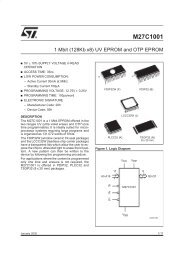
<strong>AT27C512</strong>R<br />
AC Waveforms for Read Operation (1)<br />
Notes: 1. Timing measurement reference level is 1.5V for -45 and -55 devices. Input AC drive levels are V IL = 0.0V and V IH = 3.0V.<br />
Timing measurement reference levels for all other speed grades are V OL = 0.8V and V OH = 2.0V. Input AC drive levels are<br />
V IL = 0.45V and V IH = 2.4V.<br />
2. OE/V PP may be delayed up to t CE - t OE after the falling edge of CE without impact on t CE .<br />
3. OE/V PP may be delayed up to t ACC - t OE after the address is valid without impact on t ACC .<br />
4. This parameter is only sampled and is not 100% tested.<br />
5. Output float is defined as the point when data is no longer driven.<br />
Input Test Waveforms and<br />
Measurement Levels<br />
Output Test Load<br />
For -45 and -55 devices only:<br />
t R , t F < 5 ns (10% to 90%)<br />
For -70, -90, -12, -15, and -20 devices:<br />
Note:<br />
C L = 100 pF including jig<br />
capacitance, except for<br />
the -45 and -55 devices,<br />
where C L =30 pF.<br />
t R , t F < 20 ns (10% to 90%)<br />
Pin Capacitance<br />
(f = 1 MHz T = 25°C) (1) Typ Max Units Conditions<br />
C IN 4 6 pF V IN = 0V<br />
C OUT 8 12 pF V OUT = 0V<br />
Note: 1. Typical values for nominal supply voltage. This parameter is only sampled and is not 100% tested.<br />
5