Bicycle Owner's Manual - English (.pdf 1.4 MB) - Trek Bicycle ...
Bicycle Owner's Manual - English (.pdf 1.4 MB) - Trek Bicycle ...
Bicycle Owner's Manual - English (.pdf 1.4 MB) - Trek Bicycle ...

Create successful ePaper yourself
Turn your PDF publications into a flip-book with our unique Google optimized e-Paper software.
OPEN<br />
OPEN<br />
OPEN<br />
OPEN<br />
Figure 47:<br />
Correct lever movement<br />
Figure 48:<br />
Do not turn the lever<br />
Figure 49:<br />
Test for loose condition<br />
Figure 50:<br />
Make sure the lever does<br />
not turn<br />
To remove a wheel with a Clix<br />
1. Release the Clix; move the quick-release lever<br />
to the OPEN position (Figure 45).<br />
2. Push together the cup and lever (Figure<br />
46), and push them in slightly to move the<br />
adjustment-nut out of the fork.<br />
3. Move the wheel out of the fork.<br />
To adjust the clamp-force of a Clix<br />
1. Loosen the Clix lock nut.<br />
2. Put the lever in the OPEN position (Figure 45).<br />
3. Align the marks on the lever and on the axle<br />
to the adjustment position (Figure 51).<br />
4. Tighten the adjustment-nut until it is slightly<br />
tight.<br />
5. Lock the lever and do the tests for correct<br />
clamp-force—see Step 4 of “To install a<br />
wheel with a Clix.”<br />
6. If the clamp-force is correct, lock the lever.<br />
• If the clamp force is NOT correct, slightly<br />
turn the adjusting nut clockwise to increase<br />
the clamp force. Go back to Step 4.<br />
7. To prevent a change of the adjustment,<br />
tighten the lock nut until it touches the<br />
adjustment-nut. Do not over-tighten.<br />
8. Examine the secondary wheel retention<br />
of the Clix system. Move the lever to the<br />
OPEN position. Lift the front wheel off the<br />
ground and use force to hit the top of the<br />
tire. The wheel should not come out of the<br />
fork ends. If the Clix system does not pass<br />
this test, transport your bicycle to your<br />
dealer for repair.<br />
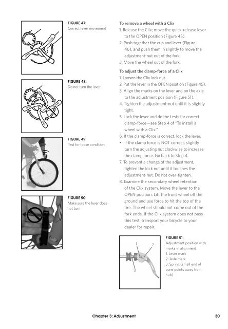
3<br />
1 2<br />
Figure 51:<br />
Adjustment position with<br />
marks in alignment<br />
1. Lever mark<br />
2. Axle mark<br />
3. Spring (small end of<br />
cone points away from<br />
hub)<br />
Chapter 3: Adjustment 30