HAT 28 Tester - coBuilder
HAT 28 Tester - coBuilder
HAT 28 Tester - coBuilder

You also want an ePaper? Increase the reach of your titles
YUMPU automatically turns print PDFs into web optimized ePapers that Google loves.
<strong>HAT</strong> <strong>28</strong><br />
<strong>Tester</strong><br />
Bedienungsanleitung<br />
Operating instructions<br />
Mode d’emploi<br />
Istruzioni d’uso<br />
Manual de instrucciones<br />
de<br />
en<br />
fr<br />
it<br />
es
A
<strong>HAT</strong> <strong>28</strong> B<br />
32<br />
<strong>28</strong><br />
24<br />
22<br />
21<br />
1<br />
3<br />
13–15<br />
19<br />
6–8<br />
26<br />
24<br />
31<br />
30<br />
27<br />
29<br />
<strong>HAT</strong> <strong>28</strong> M<br />
32<br />
<strong>28</strong><br />
21<br />
1<br />
24<br />
22<br />
4<br />
2<br />
20<br />
6–8<br />
13–15<br />
19<br />
16<br />
18<br />
30<br />
25<br />
9–12<br />
26<br />
31<br />
27<br />
29
<strong>HAT</strong> <strong>28</strong> S<br />
32<br />
26<br />
1<br />
22<br />
22<br />
20<br />
3<br />
14<br />
3<br />
25<br />
19<br />
18<br />
16<br />
6–8<br />
24<br />
31<br />
27<br />
25<br />
29<br />
<strong>HAT</strong> <strong>28</strong> E<br />
33<br />
12–14<br />
23<br />
26<br />
27<br />
19<br />
1<br />
20<br />
5<br />
25 6<br />
17
<strong>HAT</strong> <strong>28</strong> pull-out tester<br />
It is essential that the operating instructions are<br />
read before the tool is operated for the first time<br />
Always keep these operating instructions<br />
together with the tool.<br />
Ensure that the operating instructions are with<br />
the tool when it is given to other persons.<br />
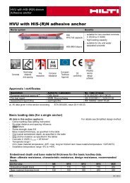
Pull-out tester A<br />
Grip<br />
Crank<br />
Coupling for removable gauge<br />
Displacement indicator scale<br />
Loading claw foot<br />
1. General information<br />
Location of identification data on the tool<br />
The type designation and serial number are printed on the<br />
type plate on the tool. Make a note of this information in your<br />
operating instructions and always refer to it when making<br />
an enquiry to your Hilti representative or service department.<br />
1.1 Safety notices and their meaning<br />
-CAUTION-<br />
Draws attention to a potentially dangerous situation that<br />
could lead to minor personal injury or damage to the equipment<br />
or other property.<br />
-NOTE-<br />
Indicates instructions and other useful information.<br />
1.2 Pictograms<br />
Warning signs<br />
General warning<br />
Obligation signs<br />
en<br />
Wear eye<br />
protection<br />
Symbols<br />
Wear a hard<br />
hat<br />
Wear protective<br />
gloves<br />
Read the<br />
operating<br />
instructions<br />
before use<br />
Return waste<br />
material for<br />
recycling<br />
A Letters and numbers refer to the illustrations. The illustrations<br />
can be found on the fold-out cover pages. Keep<br />
these pages open while you read the operating instructions.<br />
In these operating instructions, the designation “the tool”<br />
always refers to the <strong>HAT</strong> <strong>28</strong> pull-out tester.<br />
Contents<br />
Page<br />
1. General information 11<br />
2. Description 12<br />
3. Tools and accessories 12<br />
4. Technical data 15<br />
5. Safety rules 16<br />
6. Operation 16<br />
7. Care and maintenance 18<br />
8. Disposal 19<br />
9. Warranty 19<br />
10. EC declaration of conformity 19<br />
Type :<br />
Serial no.:<br />
11
en<br />
2. Description<br />
The <strong>HAT</strong> <strong>28</strong> pull-out tester is a purpose-made system for<br />
testing fastenings. It consists of a mechanical screw arrangement<br />
acting through a hydraulic load cell which measures<br />
the load applied to the fastener directly. The load value is<br />
then indicated by the strain gauge. The <strong>HAT</strong> <strong>28</strong> pull-out<br />
tester is supplied as an integral part of the <strong>HAT</strong> <strong>28</strong> “Basic”,<br />
“Master”, “Scaffold” and “Elevator” testing sets which are<br />
designed specifically for testing most small and mediumsized<br />
fastenings. A range of accessories is also available,<br />
thus further increasing the scope of possible testing applications<br />
(see Section 3.1, “Tools and accessories”).<br />
2.1 Use of the tool as directed<br />
The tool is intended for use by skilled personnel with the<br />
appropriate training and knowledge of the applicable safety<br />
precautions.<br />
• The tool and its ancillary equipment may present hazards<br />
when used incorrectly by untrained personnel or not as<br />
directed.<br />
l• Modification of the tool, or tampering with its parts, is not<br />
permissible.<br />
• To avoid the risk of injury, use only genuine Hilti fasteners,<br />
cartridges, accessories and spare parts or those of<br />
equivalent quality.<br />
• Observe the information printed in the operating instructions<br />
applicable to operation, care and maintenance.<br />
3. Tools and accessories<br />
3.1 Tools and accessories 1)<br />
<strong>Tester</strong> kit <strong>HAT</strong> <strong>28</strong> B <strong>HAT</strong> <strong>28</strong> M <strong>HAT</strong> <strong>28</strong> S <strong>HAT</strong> <strong>28</strong> E<br />
item number 355337 355338 355339 386372<br />
Tensile tester <strong>HAT</strong> <strong>28</strong> - 1 1 1 1<br />
Strain gauge 0-5 kN (1124 lbf) <strong>28</strong>5525 1<br />
Strain gauge 0-20 kN (4497 lbf) <strong>28</strong>55<strong>28</strong> 1 1<br />
Strain gauge 0-25 kN (5620 lbf) <strong>28</strong>5529 1<br />
Strain gauge 0-30 kN (6744 lbf) 274311 1<br />
Slotted button adapter set:<br />
4.5, 5.5, 6.5, 8.5, 10.5, 12.5 mm <strong>28</strong>5546 1 1 1<br />
Threaded button adapter set:<br />
1/4", 5/16", 3/8", 1/2" <strong>28</strong>5549 1 1<br />
Threaded button adapter set:<br />
M4, M5, M6, M8, M10, M12 <strong>28</strong>5543 1 1<br />
Threaded rod adapter M5 <strong>28</strong>5553 1<br />
Threaded rod adapter M6 <strong>28</strong>5555 1<br />
Threaded rod adapter M8 <strong>28</strong>5556 1<br />
Threaded rod adapter M10 <strong>28</strong>5557 1 1<br />
12
3.1 Tools and accessories 1) (continued)<br />
<strong>Tester</strong> kit <strong>HAT</strong> <strong>28</strong> B <strong>HAT</strong> <strong>28</strong> M <strong>HAT</strong> <strong>28</strong> S <strong>HAT</strong> <strong>28</strong> E<br />
item number 355337 355338 355339 386372<br />
Threaded stud adapter M12 <strong>28</strong>5558 1 1<br />
Threaded stud adapter M16 <strong>28</strong>5559 1 1 1<br />
Threaded stud adapter M20 <strong>28</strong>5560 1<br />
Adapter for scaffold ringbolts <strong>28</strong>5551 1 1<br />
Adapter for ringbolts, large 20465<strong>28</strong> 1<br />
Adapter for X-IE insulation fastener <strong>28</strong>5561 1 1 2)<br />
Adapter piece (spacer) <strong>28</strong>5531 1 1 1 1<br />
Locking adapter 2046529 1 1 1 1<br />
Set of screws M6, M8, M10, M12, M16 <strong>28</strong>5532 1<br />
Load distribution bridge 150 mm assy <strong>28</strong>5533 1 1 1<br />
Load distribution bridge 250 mm assy 274313 1<br />
Hexagon extension legs, 50 mm <strong>28</strong>5534 1 1<br />
Hexagon extension legs, 100 mm <strong>28</strong>5565 1 1 1<br />
Operating nut, 22 mm AF <strong>28</strong>5524 1 1 1<br />
Ratchet 22 mm AF <strong>28</strong>5536 1 1 1<br />
Allen wrench set: 2.5 / 3 mm <strong>28</strong>5535 1 1 1<br />
Ball driver 3 mm 2046527 1 1 1 1<br />
Adjustable wrench 0-29 mm <strong>28</strong>5541 1 1<br />
Oil bottle 50 ml <strong>28</strong>5530 1 2) 1 2) 1 2)<br />
Toolbox, 595 x 392 x 142 mm 2029176 1 1 1<br />
Toolbox, 397 x 362 x 110 mm 201899 1<br />
en<br />
1)<br />
Subject to alterations<br />
2)<br />
optional; available as accessory<br />
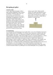
No. Part Item no.<br />
<strong>HAT</strong> <strong>28</strong> DX Accessory Set <strong>28</strong>5593<br />
1 Adapter for pull-over tests <strong>28</strong>5563<br />
2 Adapter for X-ENP / ENP2 /<br />
ENP2H / NPH, complete <strong>28</strong>5564<br />
3 Hexagon extension legs,<br />
100 mm <strong>28</strong>5565<br />
4 Open ended wrenches, 27 mm AF <strong>28</strong>5541<br />
2<br />
1 4<br />
3<br />
No. Part Item no.<br />
Miscellaneous<br />
1 Gunite test adapter<br />
set <strong>28</strong>5562<br />
2 Load distribution bridge<br />
385 mm assy 2023698<br />
3 <strong>HAT</strong> <strong>28</strong> tensile tester<br />
100 mm stroke <strong>28</strong>5570<br />
1<br />
2<br />
3<br />
Longer stroke for<br />
special applications<br />
(e.g. pull-over and<br />
scaffold anchor tests)<br />
13<br />
13
en<br />
3.2 Examples of products that can be tested<br />
<strong>Tester</strong> kit <strong>HAT</strong> <strong>28</strong> B <strong>HAT</strong> <strong>28</strong> M <strong>HAT</strong> <strong>28</strong> S <strong>HAT</strong> <strong>28</strong> E<br />
Metal anchors<br />
✔ ✔ ✔ ✔<br />
HST / HSA Kwik Bolts M16 M10 - M16<br />
HKD / HDI Flush Anchors<br />
HUS / KH Screw Anchors<br />
HLC Sleeve anchors<br />
Adhesive Anchors<br />
✔ ✔ ✔<br />
M16<br />
✔ ✔ ✔<br />
✔<br />
✔<br />
12.5 mm<br />
HVU + HAS<br />
HIT-HY / HIT-RE<br />
HIT-V<br />
Plastic Anchors<br />
HUD / HUD-L<br />
HRD 8 / HRD 10 / HRD 14<br />
Scaffold System Anchors<br />
✔ ✔ ✔<br />
M10 - M16<br />
✔ ✔ ✔<br />
M10 - M16<br />
✔ ✔ ✔<br />
✔ ✔<br />
✔ ✔<br />
M10 - M16<br />
GRS + GD<br />
✔ ✔ ✔<br />
ST + HKD<br />
Threaded studs<br />
X-BT<br />
X-M / X-CRM (on concrete)<br />
X-EM / X-CRM (on concrete)<br />
14<br />
✔<br />
✔<br />
✔<br />
✔ ✔ ✔<br />
✔<br />
✔<br />
✔
Examples of products that can be tested (continued)<br />
<strong>Tester</strong> kit <strong>HAT</strong> <strong>28</strong> B <strong>HAT</strong> <strong>28</strong> M <strong>HAT</strong> <strong>28</strong> S <strong>HAT</strong> <strong>28</strong> E<br />
Flathead nails<br />
with DX with DX<br />
Accessories Accessories<br />
X-U / X-C (on concrete and steel) Set Set<br />
with DX with DX<br />
Accessories Accessories<br />
X-CR (on concrete and steel) Set Set<br />
Decking nails<br />
en<br />
with DX with DX<br />
Accessories Accessories<br />
X-ENP / ENP2K Set Set<br />
Insulation fasteners<br />
X-IE<br />
Elevator hoist anchor points<br />
✔<br />
✔<br />
HAP 1.15<br />
Suitable for following thread sizes: M4 / M5 / M4 / M5 / M16 M10 / M12 /<br />
M6 / M8 / M6 / M8 / M16<br />
M10 / M12 M10/M12/<br />
M16/M20<br />
1/4", 5/16", 1/4", 5/16",<br />
3/8", 1/2" 3/8", 1/2"<br />
Suitable for screws, flathead nails 4.5 / 5.5 / 4.5 / 5.5 /<br />
and other fasteners with following 6.5 / 8.5 / 6.5 / 8.5 /<br />
shank diameters: 10.5 / 10.5 /<br />
12.5 mm 12.5 mm 12.5 mm<br />
Pull out load range: 0-20 kN 0-5 kN 0-20 kN 0-30 kN<br />
(4497 lbf) (1124 lbf) (4497 lbf) (6744 lbf)<br />
0-25 kN<br />
(5629 lbf)<br />
4. Technical data<br />
Tool 1) <strong>HAT</strong> <strong>28</strong> B <strong>HAT</strong> <strong>28</strong> M <strong>HAT</strong> <strong>28</strong> S <strong>HAT</strong> <strong>28</strong> E<br />
Pull-out load range 0-20 kN 0-5 kN / 0-20 kN 0-30 kN<br />
(4497 lbf) 0-25 kN (4497 lbf) (6744 lbf)<br />
(1124 lbf /<br />
5629 lbf)<br />
Maximum stroke 50 mm 50 mm 50 mm 50 mm<br />
Stroke scale mm mm mm mm<br />
Casing aluminum aluminum aluminum aluminum<br />
Weight (w/o bridge assy) 2.5 kg 2.5 kg 2.5 kg 2.5 kg<br />
Weight (with bridge assy) 4.0 kg 4.0 kg 4.0 kg 4.5 kg<br />
Eff. span of load spreading bridge 118 mm 118 mm 118 mm 207 mm<br />
15
en<br />
Strain gauge quick- quick- quick- fixed gauge<br />
release release release<br />
gauge gauge gauge<br />
Accuracy ± 2.5% ± 2.5% ± 2.5% ± 2.5%<br />
Scale reading kN / lbf kN / lbf kN / lbf kN / kg<br />
Accuracy<br />
resetable maximum load pointer<br />
Maximum load indication -40 to +60 C°<br />
Operating temperature ambient<br />
Protective rubber cover<br />
Viscous damped movement<br />
Built in protection against sudden load release<br />
Calibration certificate supplied with each strain gauge<br />
1)<br />
1) with standard accessories included in the kit<br />
5. Safety rules<br />
5.1 Basic safety rules<br />
All of these instructions must be read before using the tool<br />
and kept for future reference.<br />
5.2 Precautions at the workplace<br />
• Ensure that the working area is well lit.<br />
• Keep the workplace tidy. Objects which could cause injury<br />
should be removed from the working area. Untidiness at<br />
the workplace can lead to accidents.<br />
• Use the specified protective equipment. Wear protective<br />
glasses.<br />
• It is recommended that non-slip shoes and rubber gloves<br />
are worn when working outdoors.<br />
• Keep other persons, children in particular, away from the<br />
working area.<br />
• Avoid unfavorable body positions. Work from a secure<br />
stance and stay in balance at all times.<br />
• Do not work from a ladder.<br />
5.3 General safety precautions<br />
• Use only the genuine Hilti accessories or ancillary equipment<br />
listed in the operating instructions. Use of accessories<br />
or ancillary equipment other than the items listed<br />
in the operating instructions may present a risk of personal<br />
injury.<br />
5.3.1 Mechanical hazards<br />
• Observe the instructions concerning care and maintenance.<br />
5.4 Requirements to be met by users<br />
• The tool is designed for professional use.<br />
• The tool may be operated, serviced and repaired only by<br />
authorized, trained personnel. This personnel must be<br />
informed of any special hazards that may be encountered.<br />
• Always concentrate on your work. Proceed carefully and<br />
do not use the tool if your full attention is not on the job.<br />
6. Operation<br />
6.1 Basic testing procedure B<br />
6.1.1 The testing procedure for standard situations C<br />
1. Fit the appropriate adapter to the fastener to be tested.<br />
2. Slide the slot in the cylindrical section of the spacer over<br />
the adapter until the fastener axis and spacer axis are in<br />
alignment. (see paragraph 6.1.2)<br />
3. If necessary, adjust the length of the threaded legs until<br />
the head of the spacer can be passed through the opening<br />
in the load distribution bridge. Check that the head<br />
of the spacer is centered in the tester.<br />
4. Position the tester so that the gauge can be read conveniently.<br />
5. Adjust the length of the threaded legs so that all three are<br />
in contact with the base material). Check that the pull-out<br />
force acts in the fastener axis and parallel to the threaded<br />
legs.<br />
16
-CAUTION-<br />
Any significant misalignment at this stage will result in the<br />
threaded legs bending as the test proceeds.<br />
6. Set the red pointer of the strain gauge to zero. Hold the<br />
tester by the grip while increasing the load on the fastener<br />
by turning the crank in a clockwise direction.<br />
-CAUTION-<br />
Hold the tester securely by the grip as long as the fasteneris<br />
under load. As the load on the fastener increases, note the<br />
reading on the displacement scale on the tester. Indication<br />
of failure of the fastener may be obtained by comparing the<br />
current reading on the displacement scale with the original<br />
reading.<br />
7. Increase the load until the minimum specified load is<br />
attained.<br />
8. Release the load on the fastener by turning the crank<br />
counter-clockwise and pushing it down until the original<br />
position is reached.<br />
9. Remove the tester and the adapter.<br />
6.1.2 Using the spacer D<br />
The spacer is used either with threaded or slotted button<br />
adapters or, without an adaptor, for testing fasteners with a<br />
diameter of 16 mm diameter.<br />
It consists of a cylindrical section with a loading claw foot<br />
cut-out and an M12 threaded rod to which an M12 threaded<br />
adapter or a locking adapter can be attached. The threaded<br />
or slotted adapter for the fastener to be tested fits into a<br />
slot in the claw foot of the spacer. Then proceed as described<br />
in paragraph 6.1.1<br />
One of the load distribution bridges or the load distribution<br />
tripod is required for all applications using the spacer.<br />
6.1.3 Using the threaded button adapters<br />
(M4, M5, M6, M8, M10, M12) E<br />
– For testing threaded fasteners (e.g. stud anchors or threaded<br />
DX stud fasteners).<br />
– Screw the threaded button adapter on the projecting thread<br />
and proceed as described in paragraph 6.1.1<br />
-NOTE-<br />
An M16 nut or bolt head will usually fit straight into the loading<br />
claw foot without the need for a threaded button adapter.<br />
In exceptional cases (e.g. X-CRM fastener on steel), the<br />
tester can be used with the M4, M5, M6, M8, M10 or M12<br />
threaded button adapters without the spacer or load spreading<br />
bridge.<br />
Remove the test meter from the bridge by undoing the 3mm<br />
socket screws holding the meter on the bridge.<br />
Screw the adapter onto the protruding thread of the fixing<br />
and slide the loading claw foot of the test meter under the<br />
flange of the threaded button adapter. Then proceed as<br />
described in paragraph 6.1.1<br />
If the length of thread protruding is sufficient, the fastener<br />
may be loaded without first removing the component fastened.<br />
In this case, however, the load applied to the fastener<br />
by the component (e.g. its own weight) must also be taken<br />
into account as this load, in addition to the load applied by<br />
the pull-out tester, also acts on the fastener and increases<br />
the probability of failure.<br />
When fitting the adapter, check that a secure connection is<br />
made between the adapter and the threaded studor anchor.<br />
6.1.4 Using the slotted button adapter<br />
(4.5, 5.5, 6.5, 8.5, 10.5, 12.5 mm) F<br />
– For testing fasteners where a connection is made to the<br />
head of the bolt or anchor (e.g a hex head such as HUS-<br />
H or HRD, or a round/countersunk head, such as HLC-<br />
SK or HRD-X).<br />
-NOTE-<br />
The 6 slotted button adapters are suitable for testing fastenings<br />
within the 4 to 12 mm diameter range.<br />
These adapters are fitted under the head of the bolt or anchor<br />
in place of the item usually fastened.<br />
Slide the loading claw foot of the spacer or the test meter<br />
under the flange of the slotted button adaptor then proceed<br />
as described in paragraph 6.1.1<br />
-ATTENTION-<br />
Take care to ensure that the adapter is not damaged by tightening<br />
the fixing onto the adapter against an uneven concrete<br />
surface and distorting the adapter. We strongly recommend<br />
placing a large washer or steel plate between the<br />
adapter and the concrete surface.<br />
6.1.5 Use of the threaded rod adapters<br />
(M5, M6, M8, M10) G<br />
The M5 and M6 threaded rod adapters are equipped with<br />
an external M12 thread for use in conjunction with the M12<br />
threaded rod adapter. They are used primarily for testing<br />
remedial wall ties.<br />
The M8 and M10 threaded rod adapters are equipped with<br />
an externalM16 thread and can be used with a normal M16<br />
nut without any additional adapter.<br />
1. Connect the threaded rod adapter complete with the M12<br />
threaded button adapter to the end of the fixing, for a<br />
mechanical remedial wall tie, take care to avoid further<br />
tightening of the outer leaf expansion nut.<br />
2. If necessary, adjust the length of the threaded legs and<br />
the height of the button adapter / nut so that the adapter<br />
can be passed through the hole in the load distribution<br />
bridge fitted to the tester and into the loading claw foot.<br />
Whilst doing so, check that the adapter is centered in the<br />
tester.<br />
3. Adjust the threaded legs to minimize any play between<br />
the adapter and the tester and ensure that the pull-out<br />
force acts along the axis of the fixing being tested.<br />
-CAUTION-<br />
Do not over tighten the legs.<br />
4. Proceed as described in paragraph 6.1.1<br />
6.1.6 Using the threaded stud adapters<br />
(M12, M16, M20) H<br />
– Suitable for testing externally and internally threaded<br />
anchors (e.g. stud anchors or flush anchors).<br />
17<br />
en
en<br />
Externally threaded anchors:<br />
1. Connect the threaded rod adapter to the fixing.<br />
2. If necessary, adjust the length of the threaded legs so<br />
that the adapter can be passed through the hole in the<br />
load distribution bridge fitted to the tester and into the<br />
loading claw foot. Whilst doing so, check that the adapter<br />
is centred in the tester.<br />
3. Adjust the threaded legs to minimize any play between<br />
the adapter and the tester and ensure that the pull-out<br />
force acts along the axis of the fixing being tested.<br />
-CAUTION-<br />
Do not over tighten the legs<br />
4. Proceed as described in paragraph 6.1.1<br />
Internally threaded anchors: After the anchor has been set<br />
in accordance with the applicable instructions, a suitable<br />
threaded rod is screwed into the anchor and the adaptor<br />
then screwed onto this. The length of threaded rod to be<br />
screwed into the anchor and the adapter must be at least<br />
equal to the diameter of the anchor. Then proceed as above<br />
for externally threaded anchors.<br />
6.1.7 Using the X-IE adapter I<br />
1. Remove the insulation around the insulation fastener.<br />
2. Slide the head of the insulation fastener between the two<br />
plates of the X-IE adapter with the stem of the fixing resting<br />
in the slot in the lower plate<br />
3. If necessary, adjust the length of the threaded legs so<br />
that the adapter can be passed through the hole in the<br />
load distribution bridge fitted to the tester and into the<br />
loading claw foot. Whilst doing so, check that the adapter<br />
is centred in the tester.<br />
4. Adjust the threaded legs to minimize any play between<br />
the adapter and the tester and ensure that the pull-out<br />
force acts along the axis of the fixing being tested.<br />
-CAUTION-<br />
Do not over tighten the legs<br />
a. Proceed as described in paragraph 6.1.1<br />
6.1.8 Using the operating nut (22 mm AF) J<br />
This nut can be used with a 22 mm ratchet (supplied in the<br />
sets) for better access in confined spaces and for easier<br />
operation.<br />
1. Unscrew and remove the standard crank. Take care not<br />
to misplace the underlying washer and bearing.<br />
2. Screw on the operating nut in place of the crank.<br />
6.2 Testing scaffold anchors<br />
6.2.1 Basic setup for testing scaffold anchors<br />
(only applies to Master Kit - Scaffold Kit is already<br />
set up by default) K<br />
1. Remove the swiveling feet from the threaded legs on the<br />
load spreading bridge.<br />
2. Screw the 100 mm hexagon extension legs (hand tight)<br />
onto the threaded legs so that the end of the hexagonal<br />
section is in contact with the load distribution bridge.<br />
3. Screw the swiveling feet onto the ends of the 100mm<br />
hexagon extension legs.<br />
4. Check that the ring in the center of the chain securing the<br />
pin is attached to the ringbolt adapter and then screw on<br />
either the the M12 threaded rod adapter or the M12 locking<br />
adapter so that full thread engagement is achieved<br />
and fit it into the loading claw foot in the tester.<br />
5. If the surface of the base material is uneven fine adjustment<br />
must be carried out before performing the test.<br />
6.2.2 Using the adapter for scaffold anchor tests L<br />
1. Withdraw the pin, place the adaptor over the head of the<br />
ring bolt and then replace the pin, passing it through the<br />
ring.<br />
2. If the surface of the base material is uneven, fine adjustment<br />
must be carried out before performing the test.<br />
3. Proceed as described in paragraph 6.1.1<br />
-CAUTION-<br />
Any significant misalignment at this stage will result in the<br />
threaded legs bending as the test proceeds.<br />
7. Care and maintenance<br />
7.1 Care of metal parts<br />
Remove any dirt adhering to parts and wipe the surfaces of<br />
the tool from time to time with a damp cloth.<br />
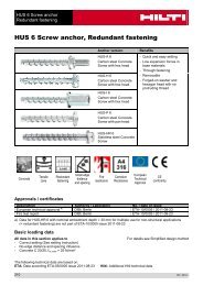
7.2 Refilling with oil<br />
(only testers with quick-release gauge)<br />
Frequent removal and reconnection of the gauge will cause<br />
the oil reservoir level to drop and will eventually affect the<br />
amount of oil available to operate the gauge. When this happens,<br />
the oil piston between the operating handle and black<br />
tester body will have retracted within the body.<br />
In this case it is recommended to send the tester to a Hilti<br />
repair center for refilling oil and overhauling the tester.<br />
18<br />
<br />
X > 5 mm ⇨ o.k.<br />
X ≤ 5 mm ⇨ refill oil
8. Disposal<br />
Most of the materials from which Hilti tools are manufactured can be recycled. The materials must be correctly separated<br />
before they can be recycled. In many countries, Hilti has already made arrangements for taking back your old tools<br />
for recycling. Please ask your Hilti customer service department or Hilti representative for further information.<br />
Should you wish to return the tool yourself to a disposal facility for recycling, proceed as follows: Dismantle the tool as<br />
far as possible without the need for special equipment. Use absorbent paper to wipe oily parts clean and to collect any<br />
oil that runs out. This papermust also be disposed of correctly. On no account should oil be allowed to enter the waste<br />
water systemor to find its way into the ground.<br />
en<br />
Part / assembly Main material Recycling<br />
Toolbox Plastic Plastics recycling<br />
Strain gauge<br />
Plastic / steel<br />
Adapter Steel Scrap metal<br />
Spacer Steel Scrap metal<br />
Load distribution bridge Steel Scrap metal<br />
Screws, small parts Steel Scrap metal<br />
Oil Oil Used oil disposal point<br />
9. Warranty<br />
Hilti warrants that the product supplied is free of defects in<br />
material and workmanship. This warranty is valid as long<br />
as the product is operated and handled correctly, cleaned<br />
and serviced properly and in accordance with the Hilti operating<br />
instructions, all warranty claims are made within 12<br />
months (unless other mandatory national regulations prescribe<br />
a longer minimum period) from the date of sale (invoice<br />
date) and the technical system is maintained, i.e. only original<br />
Hilti consumables, accessories and spare parts are<br />
used with the product.<br />
This warranty provides the free-of-charge repair or replacement<br />
of defective parts only. Parts requiring repair or replacement<br />
as a result of normal wear and tear are not covered<br />
by this warranty.<br />
Additional claims are excluded, unless mandatory national<br />
regulations prohibit such exclusion. In particular, Hilti is not<br />
obligated for direct, indirect, incidental or consequential<br />
damages, losses or expenses in connection with, or by reason<br />
of, the use of, or inability to use the product for any purpose.<br />
Implied warranties of merchantability or fitness for a<br />
particular purpose are specifically excluded.<br />
Send the product and/or related parts immediately upon<br />
discovery of a defect to the local Hilti marketing organization<br />
for repair or replacement.<br />
This constitutes Hilti’s entire obligation with regard to warranty<br />
and supersedes all prior or contemporaneous comments<br />
and oral or written agreements concerning warranties<br />
10. EC declaration of conformity<br />
Designation:<br />
Pull-out tester<br />
Type: <strong>HAT</strong> <strong>28</strong><br />
Year of design: 2004<br />
We declare, on our sole responsibility, that this product complies<br />
with the following directives or standards: 98/37/EC.<br />
Hilti Corporation<br />
Raimund Zaggl<br />
Dr. Walter Odoni<br />
Senior Vice President<br />
Vice President Development<br />
Business Area Direct Fastening<br />
Business Unit Direct Fastening<br />
09 / 2004 09 / 2004<br />
19
B<br />
C<br />
D<br />
E<br />
F<br />
G<br />
H<br />
I
J<br />
K<br />
L
Hilti Corporation<br />
LI-9494 Schaan<br />
Tel.: +423 / 234 21 11<br />
Fax:+423 / 234 29 65<br />
www.hilti.com<br />
Hilti = registered trademark of Hilti Corp., Schaan<br />
W 3044 | 0712 | 10-Pos. 1 | 1<br />
Printed in Liechtenstein © 2012<br />
Right of technical and programme changes reserved S. E. & O.<br />
<strong>28</strong>6175 / A2<br />
*<strong>28</strong>6175*<br />
<strong>28</strong>6175