

INSTALLATION INSTRUCTIONS - Lennox
INSTALLATION INSTRUCTIONS - Lennox
INSTALLATION INSTRUCTIONS - Lennox

You also want an ePaper? Increase the reach of your titles
YUMPU automatically turns print PDFs into web optimized ePapers that Google loves.
CAUTION<br />
DO NOT USE a barometric draft relief in exhaust vent<br />
pipe if outdoor combustion air is connected directly<br />
to the burner.<br />
Removal of Unit from Common Venting System<br />
In the event that an existing furnace is removed from a<br />
venting system commonly run with separate appliances,<br />
the venting system is likely to be too large to properly vent<br />
the remaining attached appliances. The following test<br />
should be conducted while each appliance is in operation<br />
and the other appliances not in operation remain connected<br />
to the common venting system. If venting system<br />
has been installed improperly, the system must be corrected<br />
as outlined in the previous section.<br />
1 − Seal any unused openings in the common venting<br />
system.<br />
2 − Visually inspect venting system for proper size and<br />
horizontal pitch and determine there is no blockage or<br />
restriction, leakage, corrosion or other deficiencies<br />
which could cause an unsafe condition.<br />
3 − Insofar as is practical, close all building doors and windows<br />
and all doors between the space in which the appliances<br />
remaining connected to the common venting<br />
system are located and other spaces of the building.<br />
Turn on clothes dryers and any appliances not connected<br />
to the common venting system. Turn on any<br />
exhaust fans, such as range hoods and bathroom exhausts,<br />
so they will operate at maximum speed. Do not<br />
operate a summer exhaust fan. Close fireplace dampers.<br />
4 − Following the lighting instruction on the unit, place the<br />
appliance being inspected in operation. Adjust thermostat<br />
so appliance will operate continuously.<br />
5 − Test for spillage using a draft gauge.<br />
6 − After it has been determined that each appliance remaining<br />
connected to the common venting system<br />
properly vents when tested as outlined above, return<br />
doors, windows, exhaust fans, fireplace dampers and<br />
any other fuel burning appliance to their previous condition<br />
of use.<br />
7 − If improper venting is observed during any of the<br />
above tests, the common venting system must be corrected.<br />
Horizontal Venting<br />
The O23 is approved for horizontal venting with the following<br />
mechanical vent systems:<br />
Tjernlund (sideshot) #SS1C (Cat. #35E08) or Field Controls<br />
#SWG−5 (Cat. #35P08) with the CK−61 (Cat. #18N28)<br />
control kit. Refer to the manufacturers’ installation instructions<br />
for proper installation procedures and service parts<br />
information.<br />
Do not use the same vent with any other appliance<br />
when using a sidewall vent system.<br />
Maximum permissible vent length is 70 equivalent feet.<br />
Minimum length is 15 equivalent feet. Calculate the equivalent<br />
vent pipe footage from the furnace to the mechanical<br />
vent system (Tjernlund or Field Controls) by adding the<br />
straight vent pipe length and the equivalent elbow lengths<br />
together.<br />
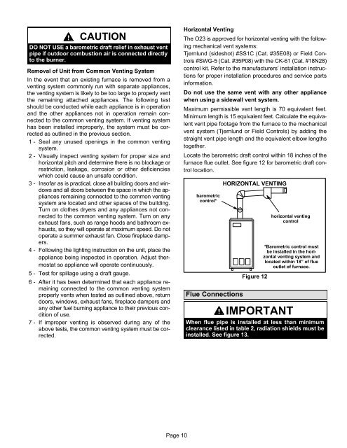
Locate the barometric draft control within 18 inches of the<br />
furnace flue outlet. See figure 12 for barometric draft control<br />
location.<br />
barometric<br />
control*<br />
Flue Connections<br />
HORIZONTAL VENTING<br />
Figure 12<br />
horizontal venting<br />
control<br />
*Barometric control must<br />
be installed in the horizontal<br />
venting system and<br />
located within 18" of flue<br />
outlet of furnace.<br />
IMPORTANT<br />
When flue pipe is installed at less than minimum<br />
clearance listed in table 2, radiation shields must be<br />
installed. See figure 13.<br />
Page 10


