

INSTALLATION INSTRUCTIONS - Lennox
INSTALLATION INSTRUCTIONS - Lennox
INSTALLATION INSTRUCTIONS - Lennox

You also want an ePaper? Increase the reach of your titles
YUMPU automatically turns print PDFs into web optimized ePapers that Google loves.
combustible<br />
material<br />
unit<br />
cabinet<br />
noncombustible<br />
spacers<br />
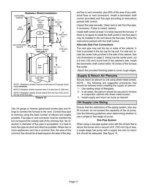
Radiation Shield Installation<br />
O23 unit<br />
(top)<br />
radiation<br />
shields<br />
ÉÉÉÉÉÉÉÉ<br />
ÉÉÉÉÉÉÉÉ<br />
ÉÉÉÉÉÉÉÉ<br />
ÉÉÉÉÉÉÉÉ<br />
ÉÉÉÉÉÉÉÉ<br />
ÉÉÉÉÉÉÉÉ<br />
A<br />
ÉÉÉÉÉÉÉÉ<br />
ÉÉÉÉÉÉÉÉ<br />
See note 2<br />
radiation shields<br />
(see note 1)<br />
ÉÉÉÉÉÉÉÉ<br />
ÉÉÉÉÉÉÉÉ<br />
ÉÉÉÉÉÉÉÉ<br />
flue<br />
pipe<br />
ÉÉÉÉÉÉÉÉ<br />
ÉÉÉÉÉÉÉÉ<br />
ÉÉÉÉÉÉÉÉ<br />
ÉÉÉÉÉÉÉÉ<br />
A<br />
1"<br />
(25 mm)<br />
min<br />
B<br />
See note 3<br />
12"<br />
(305 mm)<br />
min<br />
7"<br />
(178 mm)<br />
min<br />
Use 24 gauge or heavier galvanized smoke pipe and fittings<br />
to connect the furnace to the vent. Connect flue pipe<br />
to chimney using the least number of elbows and angles<br />
possible. Flue pipe or vent connector must be inserted into<br />
but not beyond the outside wall of the chimney flue. No reduction<br />
in diameter of flue pipe is acceptable. It is best to<br />
have flue pipe as short and direct as possible. Where two or<br />
more appliances vent into a common flue, the area of the<br />
common flue should be at least equal to the area of the largest<br />
flue or vent connector, plus 50% of the area of any additional<br />
flues or vent connectors. Install a barometric draft<br />
control (provided) and flue pipe according to instructions<br />
packed with control.<br />
Inspect flue pipe annually. Clean soot or ash from flue pipe,<br />
if necessary. If pipe is rusted, replace.<br />
Install draft control at least 12 inches beyond the furnace. If<br />
there is no space to install the draft control in the flue pipe it<br />
may be installed in the vent above the flue pipe. Follow the<br />
instructions packed with the draft control.<br />
Alternate Side Flue Connections<br />
The vent pipe may exit the top or sides of the cabinet. A<br />
hole is provided in the top cap for top exit. For side exit, locate<br />
the center hole punched in the side of the cabinet. See<br />
unit dimensions on page 2. Using it as the center point, cut<br />
a 6 inch (152 mm) round hole in the cabinet’s side. Install<br />
the barometric draft control within 18 inches of the furnace<br />
flue outlet.<br />
Attach the provided finishing plate to cover rough edges.<br />
O23 UNIT<br />
(front)<br />
ÉÉÉÉÉÉÉÉ<br />
ÉÉÉÉÉÉÉÉ<br />
NOTE 1−Radiation shields must be constructed of 24 gauge sheet<br />
metal minimum.<br />
NOTE 2−Radiation shields required when A is less than 9" (229 mm).<br />
ÉÉÉÉÉÉÉÉ<br />
NOTE 3−Radiation shields should extend from the top of the unit to<br />
the top of the flue pipe.<br />
Figure 13<br />
Supply & Return Air Plenums<br />
Secure return air plenum to unit using sheet metal screws.<br />
NOTE − The following are suggested procedures that<br />
should be followed when installing the supply air plenum.<br />
1 − Use sealing strips of fiberglass.<br />
2 − In all cases, the plenum should be secured to furnace<br />
or evaporator cabinet with sheet metal screws.<br />
3 − Install supply and return air ducts as desired.<br />
Oil Supply Line Sizing<br />
Ensure that the restrictions of the piping system, plus any<br />
lift involved, do not exceed the capability of the oil pump.<br />
Use the following guidelines when determining whether to<br />
use a single−or two−stage oil pump.<br />
One−Pipe System<br />
When using a one−pipe system even with the oil tank that is<br />
above the burner and a vacuum of 6" (152 mm) Hg or less,<br />
a single−stage fuel pump with a supply line and no return<br />
line should be adequate. See figure 14.<br />
Page 11


