

INSTALLATION INSTRUCTIONS - Lennox
INSTALLATION INSTRUCTIONS - Lennox
INSTALLATION INSTRUCTIONS - Lennox

You also want an ePaper? Increase the reach of your titles
YUMPU automatically turns print PDFs into web optimized ePapers that Google loves.
Unit Start−Up & Adjustments<br />
Before starting unit, make sure the oil tank is adequately<br />
filled with clean No. 1 or No. 2 furnace oil.<br />
NOTE − Water, rust or other contaminants in oil supply system<br />
will cause malfunction and failure of the internal parts<br />
of the fuel pump.<br />
CAUTION<br />
Never burn garbage or paper in the heating system.<br />
Never leave papers near or around the unit.<br />
CAUTION<br />
Blower door must be in place before start−up.<br />
1 − Set thermostat for heating demand and turn on electrical<br />
supply to unit.<br />
2 − Check initial air adjustment. All units are equipped with<br />
an air adjustment dial on the right side of the burner.<br />
See burner parts arrangement illustration.<br />
3 − Turn unit on. Place a can or container under the bleed<br />
port located on the fuel pump. Loosen nut on bleed port<br />
to release air and oil mixture from fuel line. Allow mixture<br />
to escape until a steady stream of oil is emitted<br />
from the port. Drain at least 1/2 pint of oil from the<br />
pump. Retighten the nut on bleed port. If lockout occurs,<br />
press reset button and continue with bleed procedure.<br />
NOTE − A two−pipe fuel system will normally bleed itself<br />
by forcing air back to the tank through the return line.<br />
This type of bleeding procedure is not necessary.<br />
4 − If burner fails to start, push reset button on primary<br />
safety control and the burner motor reset button. See<br />
part arrangement illustration.<br />
CAUTION<br />
Do not push the reset button on the primary control<br />
more than one time.<br />
5 − If the burner fails to light again, refer to the troubleshooting<br />
section in this manual.<br />
A − Fuel Pump Pressure<br />
Measure fuel pump pressure with unit off. Attach pressure<br />
gauge to pump outlet. Turn unit on and check pressure and<br />
compare to table 6. Adjust if necessary.<br />
B − Temperature Rise<br />
To measure temperature rise, place plenum thermometers<br />
in warm air and return air plenums. Locate thermometer in<br />
warm air plenum where thermometer will not see" the heat<br />
exchanger to prevent it from picking up radiant heat. Set<br />
thermostat to its highest setting to start unit. After plenum<br />
thermometers have reached their highest and steadiest<br />
readings, subtract the readings. The difference in temperatures<br />
in the supply and return air plenums should approximate<br />
the temperature rise range listed in table 6 and the appliance<br />
rating plate. If not, adjust the blower motor pulley to<br />
adjust the blower speed.<br />
Table 6<br />
O23<br />
Unit<br />
nozzle size,<br />
spray<br />
angle,<br />
& pattern<br />
pump<br />
PSIG<br />
input<br />
rating<br />
BTU/HR<br />
output<br />
rating<br />
BTU/HR<br />
head<br />
temp<br />
rise<br />
F°<br />
−70 .50GPH−80° A 100 70,000 57,000 FB0 60−70<br />
−105 .65GPH−80° B 140 105,000 84,000 FB3 65−75<br />
−120 .75GPH−80° B 140 119,000 105,000 FB3 70−80<br />
−140 .85GPH−80° B 140 140,000 112,000 FB6 65−75<br />
−154 1.0GPH−80° B 140 154,000 125,000 FB6 70−80<br />
C − Limit Control<br />
Limit Control − Do not adjust it from factory setting.<br />
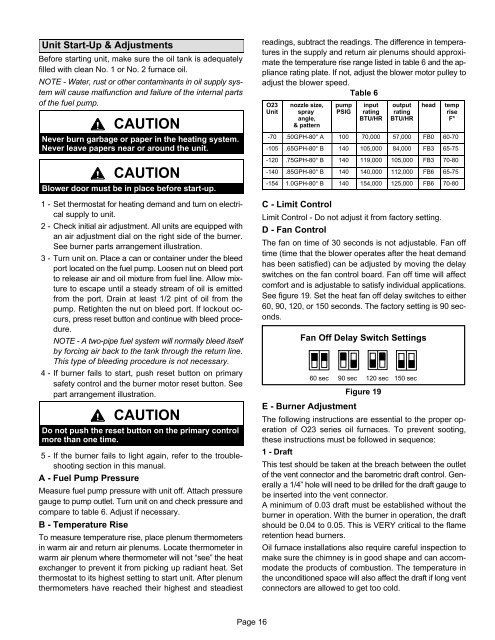
D − Fan Control<br />
The fan on time of 30 seconds is not adjustable. Fan off<br />
time (time that the blower operates after the heat demand<br />
has been satisfied) can be adjusted by moving the delay<br />
switches on the fan control board. Fan off time will affect<br />
comfort and is adjustable to satisfy individual applications.<br />
See figure 19. Set the heat fan off delay switches to either<br />
60, 90, 120, or 150 seconds. The factory setting is 90 seconds.<br />
Fan Off Delay Switch Settings<br />
60 sec<br />
90 sec<br />
E − Burner Adjustment<br />
120 sec<br />
Figure 19<br />
150 sec<br />
The following instructions are essential to the proper operation<br />
of O23 series oil furnaces. To prevent sooting,<br />
these instructions must be followed in sequence:<br />
1 − Draft<br />
This test should be taken at the breach between the outlet<br />
of the vent connector and the barometric draft control. Generally<br />
a 1/4" hole will need to be drilled for the draft gauge to<br />
be inserted into the vent connector.<br />
A minimum of 0.03 draft must be established without the<br />
burner in operation. With the burner in operation, the draft<br />
should be 0.04 to 0.05. This is VERY critical to the flame<br />
retention head burners.<br />
Oil furnace installations also require careful inspection to<br />
make sure the chimney is in good shape and can accommodate<br />
the products of combustion. The temperature in<br />
the unconditioned space will also affect the draft if long vent<br />
connectors are allowed to get too cold.<br />
Page 16


