INSTALLATION INSTRUCTIONS HS25 SERIES UNITS - Lennox
INSTALLATION INSTRUCTIONS HS25 SERIES UNITS - Lennox
INSTALLATION INSTRUCTIONS HS25 SERIES UNITS - Lennox
Create successful ePaper yourself
Turn your PDF publications into a flip-book with our unique Google optimized e-Paper software.
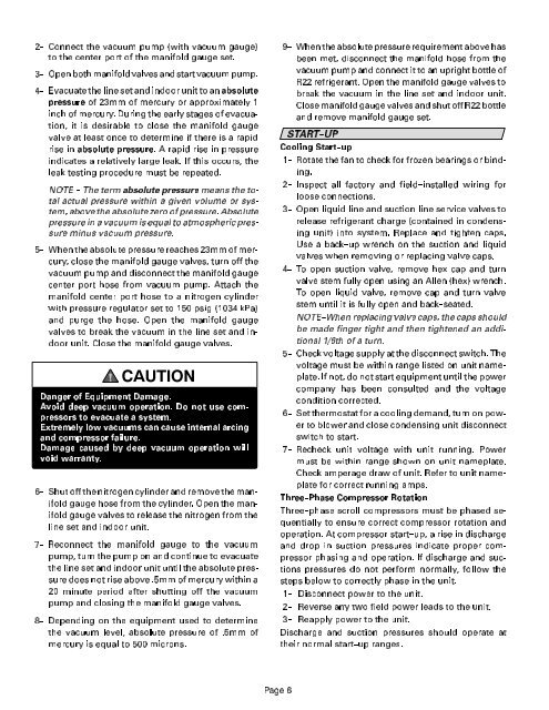
2-- Connect the vacuum pump (with vacuum gauge)<br />
to the center port of the manifold gauge set.<br />
3-- Open both manifold valves and start vacuum pump.<br />
4-- Evacuate the line set and indoor unit to anabsolute<br />
pressure of 23mm of mercury or approximately 1<br />
inch of mercury. During the early stages of evacuation,<br />
it is desirable to close the manifold gauge<br />
valve at least once to determine if there is a rapid<br />
rise in absolute pressure. A rapid rise in pressure<br />
indicates a relatively large leak. If this occurs, the<br />
leak testing procedure must be repeated.<br />
NOTE -- The term absolute pressure means the total<br />
actual pressure within a given volume or system,<br />
above the absolute zero of pressure. Absolute<br />
pressure in a vacuum is equal to atmospheric pressure<br />
minus vacuum pressure.<br />
5-- When the absolute pressure reaches 23mm of mercury,<br />
close the manifold gauge valves, turn off the<br />
vacuum pump and disconnect the manifold gauge<br />
center port hose from vacuum pump. Attach the<br />
manifold center port hose to a nitrogen cylinder<br />
with pressure regulator set to 150 psig (1034 kPa)<br />
and purge the hose. Open the manifold gauge<br />
valves to break the vacuum in the line set and indoor<br />
unit. Close the manifold gauge valves.<br />
&$87,21<br />
Danger of Equipment Damage.<br />
Avoid deep vacuum operation. Do not use compressors<br />
to evacuate a system.<br />
Extremely low vacuums can cause internal arcing<br />
and compressor failure.<br />
Damage caused by deep vacuum operation will<br />
void warranty.<br />
6-- Shut off the nitrogen cylinder and remove the manifold<br />
gauge hose from the cylinder. Open the manifold<br />
gauge valves to release the nitrogen from the<br />
line set and indoor unit.<br />
7-- Reconnect the manifold gauge to the vacuum<br />
pump, turn the pump on and continue to evacuate<br />
the line set and indoor unit until the absolute pressure<br />
does not rise above .5mm of mercury within a<br />
20 minute period after shutting off the vacuum<br />
pump and closing the manifold gauge valves.<br />
8-- Depending on the equipment used to determine<br />
the vacuum level, absolute pressure of .5mm of<br />
mercury is equal to 500 microns.<br />
9-- When the absolute pressure requirement above has<br />
been met, disconnect the manifold hose from the<br />
vacuum pump and connect it to an upright bottle of<br />
R22 refrigerant. Open the manifold gauge valves to<br />
break the vacuum in the line set and indoor unit.<br />
Close manifold gauge valves and shut off R22 bottle<br />
and remove manifold gauge set.<br />
START--UP<br />
Cooling Start--up<br />
1-- Rotate the fan to check for frozen bearings or binding.<br />
2-- Inspect all factory and field--installed wiring for<br />
loose connections.<br />
3-- Open liquid line and suction line service valves to<br />
release refrigerant charge (contained in condensing<br />
unit) into system. Replace and tighten caps.<br />
Use a back--up wrench on the suction and liquid<br />
valves when removing or replacing valve caps.<br />
4-- To open suction valve, remove hex cap and turn<br />
valve stem fully open using an Allen (hex) wrench.<br />
To open liquid valve, remove cap and turn valve<br />
stem until it is fully open and back--seated.<br />
NOTE--When replacing valve caps, the caps should<br />
be made finger tight and then tightened an additional<br />
1/6th of a turn.<br />
5-- Check voltage supply at the disconnect switch. The<br />
voltage must be within range listed on unit nameplate.<br />
If not, do not start equipment until the power<br />
company has been consulted and the voltage<br />
condition corrected.<br />
6-- Set thermostat for a cooling demand, turn on power<br />
to blower and close condensing unit disconnect<br />
switch to start.<br />
7-- Recheck unit voltage with unit running. Power<br />
must be within range shown on unit nameplate.<br />
Check amperage draw of unit. Refer to unit nameplate<br />
for correct running amps.<br />
Three--Phase Compressor Rotation<br />
Three--phase scroll compressors must be phased sequentially<br />
to ensure correct compressor rotation and<br />
operation. At compressor start--up, a rise in discharge<br />
and drop in suction pressures indicate proper compressor<br />
phasing and operation. If discharge and suctions<br />
pressures do not perform normally, follow the<br />
steps below to correctly phase in the unit.<br />
1-- Disconnect power to the unit.<br />
2-- Reverse any two field power leads to the unit.<br />
3-- Reapply power to the unit.<br />
Discharge and suction pressures should operate at<br />
their normal start--up ranges.<br />
3DJH


