

INSTALLATION INSTRUCTIONS HS25 SERIES UNITS - Lennox
INSTALLATION INSTRUCTIONS HS25 SERIES UNITS - Lennox
INSTALLATION INSTRUCTIONS HS25 SERIES UNITS - Lennox

Create successful ePaper yourself
Turn your PDF publications into a flip-book with our unique Google optimized e-Paper software.
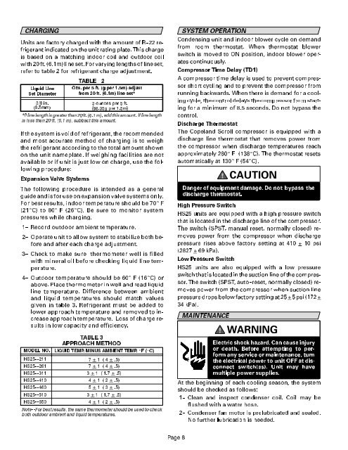
CHARGING<br />
Units are factory charged with the amount of R--22 refrigerant<br />
indicated on the unit rating plate. This charge<br />
is based on a matching indoor coil and outdoor coil<br />
with 20 ft. (6.1m) line set. For varying lengths of line set,<br />
refer to table 2 for refrigerant charge adjustment.<br />
/LTXLG /LQH<br />
6HW 'LDPHWHU<br />
LQ<br />
PP<br />
7$%/( <br />
2]V SHU IW J SHU P DGMXVW<br />
IURP IW P OLQH VHW<br />
RXQFHV SHU IW<br />
J SHU P<br />
,I OLQH OHQJWK LV JUHDWHU WKDQ IW P DGG WKLV DPRXQW ,I OLQH OHQJWK<br />
LV OHVV WKDQ IW P VXEWUDFW WKLV DPRXQW<br />
If the system is void of refrigerant, the recommended<br />
and most accurate method of charging is to weigh<br />
the refrigerant according to the total amount shown<br />
on the unit nameplate. If weighing facilities are not<br />
available or if unit is just low on charge, use the following<br />
procedure:<br />
([SDQVLRQ 9DOYH 6\VWHPV<br />
The following procedure is intended as a general<br />
guide and is for use on expansion valve systems only.<br />
For best results, indoor temperature should be 70E F<br />
(21EC) to 80E F (26EC). Be sure to monitor system<br />
pressures while charging.<br />
1-- Record outdoor ambient temperature.<br />
2-- Operate unit to allow system to stabilize both before<br />
and after each charge adjustment.<br />
3-- Check to make sure thermometer well is filled<br />
with mineral oil before checking liquid line temperature.<br />
4-- Outdoor temperature should be 60E F(16EC) or<br />
above. Place thermometer in well and read liquid<br />
line temperature. Difference between ambient<br />
and liquid temperatures should match values<br />
given in table 3. Refrigerant must be added to<br />
lower approach temperature and removed to increase<br />
approach temperature. Loss of charge results<br />
in low capacity and efficiency.<br />
02'(/ 12<br />
+6 <br />
+6 <br />
+6 <br />
+6 <br />
+6 <br />
+6 <br />
+6 <br />
7$%/( <br />
$3352$&+ 0(7+2'<br />
/,48,' 7(03 0,186 $0%,(17 7(03 E) E&<br />
<br />
<br />
<br />
<br />
<br />
<br />
<br />
1RWH )RU EHVW UHVXOWV WKH VDPH WKHUPRPHWHU VKRXOG EH XVHG WR FKHFN<br />
ERWK RXWGRRU DPELHQW DQG OLTXLG WHPSHUDWXUHV<br />
SYSTEM OPERATION<br />
Condensing unit and indoor blower cycle on demand<br />
from room thermostat. When thermostat blower<br />
switch is moved to ON position, indoor blower operates<br />
continuously.<br />
Compressor Time Delay (TD1)<br />
A compressor time delay is used to prevent compressor<br />
short cycling and to prevent the compressor from<br />
running backwards. When there is demand for a cooling<br />
cycle, the control delays the compressor from starting<br />
for a minimum of 8.5 seconds. Do not bypass the<br />
control.<br />
Discharge Thermostat<br />
The Copeland Scroll compressor is equipped with a<br />
discharge line thermostat that removes power from<br />
the compressor when discharge temperatures reach<br />
approximately 280E F (138EC). The thermostat resets<br />
automatically at 130E F (54EC).<br />
CAUTION<br />
Danger of equipment damage. Do not bypass the<br />
discharge thermostat.<br />
High Pressure Switch<br />
<strong>HS25</strong> units are equipped with a high pressure switch<br />
that is located in the discharge line of the compressor.<br />
The switch (SPST, manual reset, normally closed) removes<br />
power from the compressor when discharge<br />
pressure rises above factory setting at 410 + 10 psi<br />
(2827 + 69 kPa).<br />
Low Pressure Switch<br />
<strong>HS25</strong> units are also equipped with a low pressure<br />
switch that is located in the suction line of the compressor.<br />
The switch (SPST, auto--reset, normally closed) removes<br />
power from the compressor when suction line<br />
pressure drops below factory setting at 25 +5 psi (172 +<br />
34 kPa).<br />
MAINTENANCE<br />
WARNING<br />
Electric shock hazard. Can cause injury<br />
or death. Before attempting to perform<br />
any service or maintenance, turn<br />
the electrical power to unit OFF at disconnect<br />
switch(es). Unit may have<br />
multiple power supplies.<br />
At the beginning of each cooling season, the system<br />
should be checked as follows:<br />
1-- Clean and inspect condenser coil. Coil may be<br />
flushed with a water hose.<br />
2-- Condenser fan motor is prelubricated and sealed.<br />
No further lubrication is needed.<br />
3DJH


