NBN Co Network Design Rules
NBN Co Network Design Rules
NBN Co Network Design Rules

Create successful ePaper yourself
Turn your PDF publications into a flip-book with our unique Google optimized e-Paper software.
<strong>NBN</strong> <strong>Co</strong> <strong>Network</strong> <strong>Design</strong> <strong>Rules</strong><br />
1.1.11.5. POI Aggregation Switch<br />
The POI Aggregation Switch is deployed in pairs in POI sites to aggregate the Wireless Access traffic<br />
from FAN sites. The switches are shared infrastructure, providing both this function and the<br />
function of the Ethernet Access Switch (EAS) of the Aggregation Domain.<br />
1.1.12. Packet Data <strong>Network</strong> Gateway (PDN-GW)<br />
The PDN-GW supports up to 25000 WNTDs. It is provided as a pair for resiliency, each with its own<br />
internal resiliency of controller, traffic and line cards.<br />
The PDN-GW has 2 4 x 10 Gigabit Ethernet (SFP+) interfaces to the Aggregation Domain for resilient<br />
network connectivity, and 2 4 x 10 Gigabit Ethernet (SFP+) interfaces to the POI Aggregation Switch<br />
pair for resilient network connectivity. The system is fed by -48VDC power, and power module/feed<br />
redundancy is incorporated into the shelf.<br />
1.1.13. Wireless Access Planning Hierarchy<br />
For planning, design, and construction purposes the network is divided into hierarchical modules<br />
and network entities.<br />
These modules are used to provide the planning constructs needed to provide connectivity between<br />
the individual End-Users premise through to the Access Seeker (AS) Point of Interconnection (POI)<br />
The first identifiable connection point is an end-user premise. These are defined as physical address<br />
points. Each individual dwelling unit is required to have a unique service location, and is identified as<br />
a premises.<br />
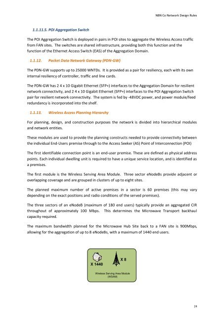
The first module is the Wireless Serving Area Module. Three sector eNodeBs provide adjacent or<br />
overlapping coverage and are grouped in clusters of up to eight sites.<br />
The planned maximum number of active premises in a sector is 60 premises (this may vary<br />
depending on the exact positions and radio conditions of the served premises).<br />
The three sectors of an eNodeB (maximum of 180 end users) typically provide an aggregated CIR<br />
throughout of approximately 100 Mbps. This determines the Microwave Transport backhaul<br />
capacity required.<br />
The maximum bandwidth planned for the Microwave Hub Site back to a FAN site is 900Mbps,<br />
allowing for the aggregation of up to 8 eNodeBs, with a maximum of 1440 end users.<br />
X 1440<br />
X 8<br />
Wireless Serving Area Module<br />
(WSAM)<br />
24