NBN Co Network Design Rules
NBN Co Network Design Rules
NBN Co Network Design Rules
Create successful ePaper yourself
Turn your PDF publications into a flip-book with our unique Google optimized e-Paper software.
<strong>NBN</strong> <strong>Co</strong> <strong>Network</strong> <strong>Design</strong> <strong>Rules</strong><br />
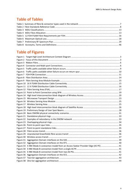
Table of Tables<br />
Table 1 Summary of fibre & connector types used in the network .......................................................................... 7<br />
Table 2 Fibre Standards Reference <strong>Co</strong>de .................................................................................................................... 8<br />
Table 3 MDU Classifications ...................................................................................................................................... 13<br />
Table 4 MDU Fibre Allocation: .................................................................................................................................. 13<br />
Table 5 12 FDH FSAM Fibre Requirements per FDH................................................................................................ 16<br />
Table 6 Maximum Optical Loss ................................................................................................................................. 18<br />
Table 7 Preliminary RF Spectrum Plan ..................................................................................................................... 29<br />
Table 8 Acronyms, Terms and Definitions ............................................................................................................... 46<br />
Table of Figures<br />
Figure 1 Target High Level Architecture <strong>Co</strong>ntext Diagram ....................................................................................... 3<br />
Figure 2 Focus of this Document ................................................................................................................................ 3<br />
Figure 3 Ribbon Fibre................................................................................................................................................... 6<br />
Figure 4 <strong>Co</strong>nnector and Multi-port <strong>Co</strong>nnections....................................................................................................... 6<br />
Figure 5 Traffic paths available when failure occurs ................................................................................................. 9<br />
Figure 6 Traffic paths available when failure occurs on return spur...................................................................... 10<br />
Figure 7 FDH PON <strong>Co</strong>nnection .................................................................................................................................. 11<br />
Figure 8 Fibre Distribution Area................................................................................................................................ 14<br />
Figure 9 Fibre Serving Area Module Example .......................................................................................................... 15<br />
Figure 10 16 X FSAM Distribution Cable <strong>Co</strong>nnectivity............................................................................................. 15<br />
Figure 11 12 X FSAM Distribution Cable <strong>Co</strong>nnectivity............................................................................................. 16<br />
Figure 12 Fibre Serving Area (FSA)............................................................................................................................ 17<br />
Figure 13 Point to Point <strong>Co</strong>nnection using DFN ...................................................................................................... 19<br />
Figure 14 High level interconnection block diagram of Wireless Access ............................................................... 20<br />
Figure 15 Microwave Transport <strong>Design</strong> ................................................................................................................... 23<br />
Figure 16 Wireless Serving Area Module ................................................................................................................. 25<br />
Figure 17 Wireless Serving Area ............................................................................................................................... 25<br />
Figure 18 High level interconnection block diagram of Satellite Access ............................................................... 26<br />
Figure 19 Preliminary <strong>Design</strong> of User Spot Beams .................................................................................................. 28<br />
Figure 20 Basic DWDM physical connectivity scenarios ......................................................................................... 31<br />
Figure 21 Standalone physical rings ......................................................................................................................... 33<br />
Figure 22 Examples of redundancy in the DWDM network ................................................................................... 33<br />
Figure 23 Overlapping physical rings ........................................................................................................................ 34<br />
Figure 26 Point-to-point spur links ........................................................................................................................... 35<br />
Figure 27 Point-to-point standalone links ................................................................................................................ 35<br />
Figure 28 Fibre access transit .................................................................................................................................... 36<br />
Figure 29 Unprotected Greenfields fibre access transit ......................................................................................... 36<br />
Figure 30 Wireless access transit .............................................................................................................................. 37<br />
Figure 31 Aggregation Domain interfaces on the EAS ............................................................................................ 39<br />
Figure 32 Aggregation Domain interfaces on the EFS ............................................................................................. 40<br />
Figure 33 E-NNI Mode A connection model from an Access Seeker Provider Edge (AS PE) ................................ 41<br />
Figure 34 E-NNI Mode B connection model from a single AS PE ........................................................................... 41<br />
Figure 35 E-NNI Mode B connection model from two AS PEs ................................................................................ 41<br />
Figure 36 Aggregation Domain interfaces on the ECS............................................................................................. 42<br />
Figure 37 Two tier aggregation architecture ........................................................................................................... 43<br />
Figure 38 One tier aggregation architecture ........................................................................................................... 44<br />
iii


