Bibliography - School of Physics - University of Melbourne
Bibliography - School of Physics - University of Melbourne
Bibliography - School of Physics - University of Melbourne

You also want an ePaper? Increase the reach of your titles
YUMPU automatically turns print PDFs into web optimized ePapers that Google loves.
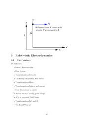
136 CHAPTER 10. RUTHERFORD SCATTERING<br />
10.4.2.1 Detector and electronics<br />
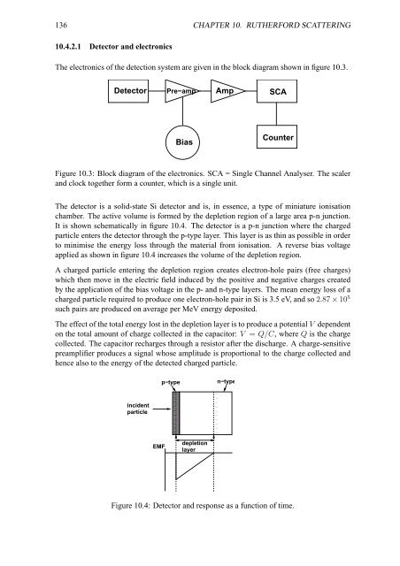
The electronics <strong>of</strong> the detection system are given in the block diagram shown in figure 10.3.<br />
Detector Pre−amp Amp SCA<br />
Bias<br />
Counter<br />
Figure 10.3: Block diagram <strong>of</strong> the electronics. SCA = Single Channel Analyser. The scaler<br />
and clock together form a counter, which is a single unit.<br />
The detector is a solid-state Si detector and is, in essence, a type <strong>of</strong> miniature ionisation<br />
chamber. The active volume is formed by the depletion region <strong>of</strong> a large area p-n junction.<br />
It is shown schematically in figure 10.4. The detector is a p-n junction where the charged<br />
particle enters the detector through the p-type layer. This layer is as thin as possible in order<br />
to minimise the energy loss through the material from ionisation. A reverse bias voltage<br />
applied as shown in figure 10.4 increases the volume <strong>of</strong> the depletion region.<br />
A charged particle entering the depletion region creates electron-hole pairs (free charges)<br />
which then move in the electric field induced by the positive and negative charges created<br />
by the application <strong>of</strong> the bias voltage in the p- and n-type layers. The mean energy loss <strong>of</strong> a<br />
charged particle required to produce one electron-hole pair in Si is 3.5 eV, and so 2.87 × 10 5<br />
such pairs are produced on average per MeV energy deposited.<br />
The effect <strong>of</strong> the total energy lost in the depletion layer is to produce a potential V dependent<br />
on the total amount <strong>of</strong> charge collected in the capacitor: V = Q/C, where Q is the charge<br />
collected. The capacitor recharges through a resistor after the discharge. A charge-sensitive<br />
preamplifier produces a signal whose amplitude is proportional to the charge collected and<br />
hence also to the energy <strong>of</strong> the detected charged particle.<br />
p−type<br />
n−type<br />
incident<br />
particle<br />
+<br />
+<br />
+<br />
+<br />
+<br />
+<br />
+<br />
+<br />
+<br />
+<br />
−<br />
−<br />
−<br />
−<br />
−<br />
−<br />
−<br />
−<br />
−<br />
−<br />
EMF<br />
depletion<br />
layer<br />
Figure 10.4: Detector and response as a function <strong>of</strong> time.