1320.chp:Corel VENTURA - Tyco Fire Products
1320.chp:Corel VENTURA - Tyco Fire Products
1320.chp:Corel VENTURA - Tyco Fire Products

You also want an ePaper? Increase the reach of your titles
YUMPU automatically turns print PDFs into web optimized ePapers that Google loves.
TFP1320<br />
Page 7 of 14<br />
NOTES:<br />
1. Install subassemblies in alphabetical order.<br />
2. See Figure 2 of TFP1305 for Valve Port<br />
identification.<br />
3. Route all Tubing to Drip Funnel.<br />
4. When DV-5 trips, the Automatic Shut-Off Valve<br />
shuts off the diaphragm chamber supply.<br />
5. Nipples 1-5 vary in length relative to the Model<br />
DV-5 size. Select per the table. All other nipples<br />
packed unassembled shall be installed per the<br />
appropriate trim exploded view, Figure 2A Part<br />
1, 2, or 3.<br />
WATERFLOW<br />
PRESSURE ALARM<br />
SWITCH, ORDERED<br />
SEPARATELY<br />
3/4 INCH NPT<br />
CONNECTION FOR<br />
WATER MOTOR<br />
ALARM<br />
NIPPLE<br />
1<br />
NIPPLE<br />
4<br />
MAIN<br />
DRAIN VALVE<br />
(NORMALLY<br />
CLOSED)<br />
SYSTEM<br />
WATER<br />
SUPPLY<br />
PRESSURE<br />
GAUGE<br />
ALARM<br />
TEST VALVE<br />
(NORMALLY<br />
CLOSED)<br />
C<br />
B<br />
DRIP<br />
FUNNEL<br />
1-1/4 INCH NPT<br />
CONNECTION<br />
TO DRAIN<br />
Nipple<br />
Number<br />
1<br />
2<br />
3<br />
4<br />
A<br />
MAIN DRAIN<br />
CONNECTION<br />
(SIZED PER<br />
TABLE)<br />
1-1/2" (DN40)<br />
1/2" x Close<br />
1/2" x Close<br />
1/2" x 5"<br />
3/4" x 1-1/2"<br />
AUTOMATIC<br />
DRAIN VALVE<br />
NIPPLE<br />
5<br />
Select Appropriate Nipple Sizes per DV-5 Deluge Valve Size<br />
2" (DN50)<br />
1/2" x 2"<br />
1/2" x Close<br />
1/2" x 5-1/2"<br />
3/4" x 1-1/2"<br />
5 3/4" x 1-1/2" 3/4" x 2-1/2"<br />
Main Drain<br />
Size<br />
VENT FITTING<br />
(GREEN TINT)<br />
SYSTEM<br />
DRAIN VALVE<br />
(NORMALLY<br />
CLOSED)<br />
DIAPHRAGM<br />
CHAMBER SUPPLY<br />
CONTROL VALVE<br />
(NORMALLY<br />
OPEN)<br />
3" (DN80)<br />
1/2" x 1-1/2"<br />
1/2" x 1-1/2"<br />
1/2" x 7"<br />
3/4" x 1-1/2"<br />
3/4" x 4-1/2"<br />
SOLENOID VALVE,<br />
ORDERED SEPARATELY<br />
(NORMALLY CLOSED)<br />
4" (DN100)<br />
FLANGE x FLANGE<br />
MODEL DV-5<br />
DELUGE VALVE<br />
SHOWN<br />
1/2 INCH NPT<br />
CONNECTION FROM<br />
WATER SUPPLY<br />
4" (DN100) 6" (DN150)<br />
1/2" x 2-1/2" 1/2" x 5-1/2"<br />
1/2" x 2" 1/2" x 3"<br />
1/2" x 6-1/2" 1/2" x 7-1/2"<br />
3/4" x 2-1/2" 3/4" x 3-1/2"<br />
1" x 6" 1" x 9"<br />
3/4" NPT 3/4" NPT 1-1/4" NPT 2" NPT 2" NPT<br />
1/2 INCH CONDUIT<br />
CONNECTION<br />
FOR "ELECTRIC<br />
DETECTION"<br />
AUTOMATIC<br />
SHUT-OFF VALVE<br />
(NORMALLY<br />
OPEN)<br />
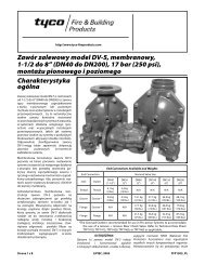
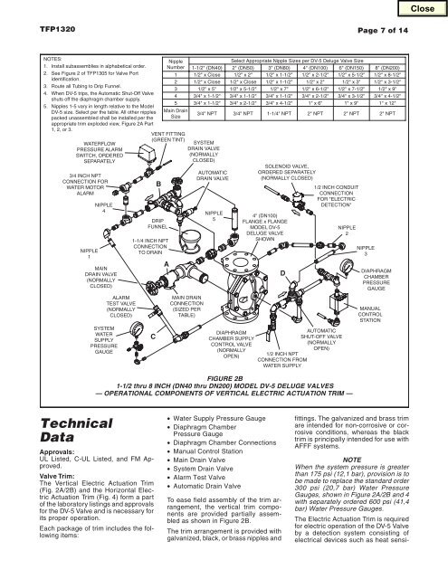
FIGURE 2B<br />
1-1/2 thru 8 INCH (DN40 thru DN200) MODEL DV-5 DELUGE VALVES<br />
— OPERATIONAL COMPONENTS OF VERTICAL ELECTRIC ACTUATION TRIM —<br />
D<br />
NIPPLE<br />
2<br />
NIPPLE<br />
3<br />
MANUAL<br />
CONTROL<br />
STATION<br />
8" (DN200)<br />
1/2" x 8-1/2"<br />
1/2" x 3-1/2"<br />
1/2" x 9"<br />
3/4" x 4-1/2"<br />
1" x 12"<br />
2" NPT<br />
DIAPHRAGM<br />
CHAMBER<br />
PRESSURE<br />
GAUGE<br />
Technical<br />
Data<br />
Approvals:<br />
UL Listed, C-UL Listed, and FM Approved.<br />
Valve Trim:<br />
The Vertical Electric Actuation Trim<br />
(Fig. 2A/2B) and the Horizontal Electric<br />
Actuation Trim (Fig. 4) form a part<br />
of the laboratory listings and approvals<br />
for the DV-5 Valve and is necessary for<br />
its proper operation.<br />
Each package of trim includes the following<br />
items:<br />
• Water Supply Pressure Gauge<br />
• Diaphragm Chamber<br />
Pressure Gauge<br />
• Diaphragm Chamber Connections<br />
• Manual Control Station<br />
• Main Drain Valve<br />
• System Drain Valve<br />
• Alarm Test Valve<br />
• Automatic Drain Valve<br />
To ease field assembly of the trim arrangement,<br />
the vertical trim components<br />
are provided partially assembled<br />
as shown in Figure 2B.<br />
The trim arrangement is provided with<br />
galvanized, black, or brass nipples and<br />
fittings. The galvanized and brass trim<br />
are intended for non-corrosive or corrosive<br />
conditions, whereas the black<br />
trim is principally intended for use with<br />
AFFF systems.<br />
NOTE<br />
When the system pressure is greater<br />
than 175 psi (12,1 bar), provision is to<br />
be made to replace the standard order<br />
300 psi (20,7 bar) Water Pressure<br />
Gauges, shown in Figure 2A/2B and 4<br />
with separately ordered 600 psi (41,4<br />
bar) Water Pressure Gauges.<br />
The Electric Actuation Trim is required<br />
for electric operation of the DV-5 Valve<br />
by a detection system consisting of<br />
electrical devices such as heat sensi-