Table Of Contents
Table Of Contents
Table Of Contents

Create successful ePaper yourself
Turn your PDF publications into a flip-book with our unique Google optimized e-Paper software.
<strong>Table</strong> of <strong>Contents</strong><br />
Subject<br />
Page<br />
MS S54 . . . . . . . . . . . . . . . . . . . . . . . . . . . . . . . . . . . . . . . . . . . . . . . . . . . .2<br />
Objectives of the Module . . . . . . . . . . . . . . . . . . . . . . . . . . . . . . . . . . . . .2<br />
Purpose of the System . . . . . . . . . . . . . . . . . . . . . . . . . . . . . . . . . . . . . . .3<br />
System Components . . . . . . . . . . . . . . . . . . . . . . . . . . . . . . . . . . . . . . . .4<br />
Power Supply . . . . . . . . . . . . . . . . . . . . . . . . . . . . . . . . . . . . . . . . . . . . . .6<br />
Principle of Operation . . . . . . . . . . . . . . . . . . . . . . . . . . . . . . . . . . . . . . . .7<br />
Workshop Hints . . . . . . . . . . . . . . . . . . . . . . . . . . . . . . . . . . . . . . . . . . . .8<br />
Tools and Equipment . . . . . . . . . . . . . . . . . . . . . . . . . . . . . . . . . . . . . . . .9<br />
Air Management. . . . . . . . . . . . . . . . . . . . . . . . . . . . . . . . . . . . . . . . . . . . 10<br />
Principle of Operation. . . . . . . . . . . . . . . . . . . . . . . . . . . . . . . . . . . . . . . .14<br />
Workshop Hints. . . . . . . . . . . . . . . . . . . . . . . . . . . . . . . . . . . . . . . . . . . .21<br />
Tools and Equipment. . . . . . . . . . . . . . . . . . . . . . . . . . . . . . . . . . . . . . . .23<br />
Fuel Management. . . . . . . . . . . . . . . . . . . . . . . . . . . . . . . . . . . . . . . . . . .24<br />
Principle of Operation. . . . . . . . . . . . . . . . . . . . . . . . . . . . . . . . . . . . . . . 33<br />
Workshop Hints. . . . . . . . . . . . . . . . . . . . . . . . . . . . . . . . . . . . . . . . . . . .39<br />
Tools and Equipment. . . . . . . . . . . . . . . . . . . . . . . . . . . . . . . . . . . . . . . .45<br />
Ignition Management. . . . . . . . . . . . . . . . . . . . . . . . . . . . . . . . . . . . . . . . 47<br />
Principle of Operation. . . . . . . . . . . . . . . . . . . . . . . . . . . . . . . . . . . . . . . 53<br />
Workshop Hints. . . . . . . . . . . . . . . . . . . . . . . . . . . . . . . . . . . . . . . . . . . .57<br />
Tools and Equipment. . . . . . . . . . . . . . . . . . . . . . . . . . . . . . . . . . . . . . . .61<br />
Emissions Management. . . . . . . . . . . . . . . . . . . . . . . . . . . . . . . . . . . . . . 62<br />
Evaporative Emissions. . . . . . . . . . . . . . . . . . . . . . . . . . . . . . . . . . . . . . . 62<br />
Exhaust Emissions. . . . . . . . . . . . . . . . . . . . . . . . . . . . . . . . . . . . . . . . . .65<br />
Principle of Operation. . . . . . . . . . . . . . . . . . . . . . . . . . . . . . . . . . . . . . . .70<br />
Workshop Hints. . . . . . . . . . . . . . . . . . . . . . . . . . . . . . . . . . . . . . . . . . . 81<br />
Tools and Equipment . . . . . . . . . . . . . . . . . . . . . . . . . . . . . . . . . . . . . . . 82<br />
Performance Controls. . . . . . . . . . . . . . . . . . . . . . . . . . . . . . . . . . . . . . . 84<br />
Review Questions . . . . . . . . . . . . . . . . . . . . . . . . . . . . . . . . . . . . . . . . . . 88
Emissions Management<br />
Evaporative Emissions: The<br />
control of the evaporative fuel<br />
vapors (Hydrocarbons) from the<br />
fuel tank is important for the overall<br />
reduction in vehicle emissions.<br />
The evaporative system has been<br />
combined with the ventilation of<br />
the fuel tank, which allows the<br />
tank to breath (equalization). The<br />
overall operation provides:<br />
VAPORS TO EVAPORATIVE<br />
EMISSION VALVE<br />
DM-TL<br />
FILTER<br />
• An inlet vent, to an otherwise<br />
"sealed" fuel tank, for the entry<br />
of air to replace the fuel consumed<br />
during engine operation.<br />
13410095.eps<br />
• An outlet vent with a storage canister to "trap and hold" fuel vapors that are produced by<br />
the expansion/evaporation of fuel in the tank, when the vehicle is stationary.<br />
The canister is then "purged" using the engine vacuum to draw the fuel vapors into the<br />
combustion chamber. This "cleans" the canister allowing for additional storage. Like any<br />
other form of combustible fuel, the introduction of these vapors on a running engine must<br />
be controlled. The ECM controls the Evaporative Emission Valve which regulates purging of<br />
evaporative vapors.<br />
ON-BOARD REFUELING VAPOR RECOVERY (ORVR)<br />
The ORVR system recovers and stores hydrocarbon fuel vapor that was previously released<br />
during refueling. Non ORVR vehicles vent fuel vapors from the tank venting line back to the<br />
filler neck and in many states reclaimed by a vacuum receiver on the filling station’s fuel<br />
pump nozzle.<br />
When refueling, the pressure of the fuel entering the tank forces the hydrocarbon vapors<br />
through the tank vent line to the liquid/ vapor separator, through the rollover valve and into<br />
the charcoal canister.<br />
The HC is stored in the charcoal canister, and the system can then “breath” through the DM<br />
TL and the air filter.<br />
62<br />
MS S54 Emissions Management
Liquid/Vapor Separator: Fuel vapors are routed from<br />
the fuel tank filler neck through a hose to the<br />
Liquid/Vapor Separator (located in the right rear wheel<br />
well behind the trim).<br />
The vapors cool when exiting the fuel tank, the condensates<br />
separate and drain back to the fuel tank<br />
through a return hose (1). The remaining vapors exit the<br />
Liquid/ Vapor Separator to the Active Carbon Canister.<br />
134100143.eps<br />
Active Carbon Canister: As the fuel vapors enter the<br />
canister, they will be absorbed by the active carbon.<br />
The remaining air will be vented to the atmosphere<br />
through the end of the canister (passing through the<br />
DMTL and filter) allowing the fuel tank to “breath”.<br />
When the engine is running, the canister is then<br />
"purged" using intake manifold vacuum to draw fresh<br />
air through the canister which extracts the hydrocarbon<br />
vapors into the combustion chamber. This cleans the<br />
canister for additional storage. The Active Carbon<br />
Canister is located under the luggage compartment<br />
floor with the DM TL Pump.<br />
134100147.eps<br />
Evaporative Emission Valve: This ECM controlled<br />
solenoid valve (located under the intake manifold) regulates<br />
the purge flow from the Active Carbon Canister<br />
through the idle air distribution pipe into the intake<br />
manifold .<br />
The ECM Relay provides operating voltage, and the<br />
ECM controls the valve by regulating the ground circuit.<br />
The valve is powered open and closed by an internal<br />
spring.<br />
134100101.eps<br />
MS S54<br />
FROM EVAPORATIVE<br />
EMISSION CANISTER<br />
ECM RELAY<br />
If the Evaporative Emission Valve circuit is defective, a<br />
fault code will be set and the “Malfunction Indicator<br />
Light” will be illuminated. If the valve is “mechanically”<br />
defective, a driveability complaint could be encountered<br />
and a mixture related fault code will be set.<br />
134100100.eps<br />
63<br />
MS S54 Emissions Management
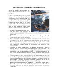
DMTL (Diagnosis Module - Evaporative Leakage<br />
Detection): This component ensures accurate fuel<br />
system leak detection for leaks as small as 1.0 mm<br />
(.040”) by slightly pressurizing the fuel tank and evaporative<br />
components. The DM TL pump contains an integral<br />
DC motor which is activated directly by the ECM.<br />
The ECM monitors the pump motor operating current<br />
as the measurement for detecting leaks.<br />
The pump also contains an ECM controlled change<br />
over valve that is energized closed during a Leak<br />
Diagnosis test. The change over valve is open during all<br />
other periods of operation allowing the fuel system to<br />
“breath” through the inlet filter. The DM TL is located<br />
under the luggage compartment floor with the Active<br />
Carbon Canister.<br />
13410089.eps<br />
1<br />
2<br />
1. In its inactive state, filtered fresh air enters the evaporative<br />
system through the sprung open valve of the<br />
DM TL.<br />
2. When the DME activates the DM TL for leak testing,<br />
it first activates only the pump motor. This pumps air<br />
through a restricted orifice (1.0 mm) which causes<br />
the electric motor to draw a specific amperage<br />
value. This value is equivalent to the size of the<br />
restricted.<br />
3. The solenoid valve is then energized which seals the<br />
evaporative system and directs the pump output to<br />
pressurize the evaporative system.<br />
13410088.eps<br />
3<br />
• A large leak is detected in the evaporative system if<br />
the amperage value is not achieved.<br />
• A small leak is detected if the same reference amper<br />
age is achieved.<br />
• The system is sealed if the amperage value is higher<br />
than the reference amperage.<br />
64<br />
MS S54 Emissions Management<br />
13410087.eps
Exhaust Emissions: The combustion<br />
process of a gasoline<br />
powered engine produces Carbon<br />
Monoxide (CO), Hydrocarbons<br />
(HC) and Oxides of Nitrogen<br />
(NOx).<br />
• Carbon Monoxide is a product<br />
of incomplete combustion under<br />
conditions of air deficiency.<br />
CO emissions are strongly dependent<br />
on the air/fuel ratio.<br />
• Hydrocarbons are also a product<br />
of incomplete combustion<br />
which results in unburned fuel.<br />
HC emissions are dependent on<br />
air/fuel ratio and the ignition of<br />
the mixture.<br />
134100103-1.eps<br />
• Oxides of Nitrogen are a product of peak combustion temperature (and temperature<br />
duration). NOx emissions are dependent on internal cylinder temperatures affected by<br />
the air/fuel ratio and ignition of the mixture.<br />
Control of exhaust emissions is accomplished by the engine and engine management<br />
design as well as after-treatment.<br />
• The ECM manages exhaust emissions by controlling the air/fuel ratio and ignition.<br />
• The Catalytic Converter further reduces exhaust emissions leaving the engine.<br />
Bosch LSH 25 Oxygen Sensors: The pre-cat<br />
oxygen sensors (1) measure the residual oxygen<br />
content of the exhaust gas. The sensors produces<br />
a low voltage (0-1000 mV) proportional to<br />
the oxygen content that allows the ECM to<br />
monitor the air/fuel ratio.<br />
If necessary, the ECM will “correct” the air/fuel<br />
ratio by regulating the ms injection time. The<br />
sensor is mounted in the hot exhaust stream<br />
directly in front of the catalytic converter.<br />
11410049.tiff<br />
65<br />
MS S54 Emissions Management
Ambient Air<br />
Exhaust<br />
Stream<br />
12410005.bmp<br />
1. Electrode (+) 7. External Body (Ventilated)<br />
2. Electrode (-) 8. Contact Spring<br />
3. Porous Ceramic Coating (encasing electrolyte) 9. Vent Opening<br />
4. Protective Metal Cage (Ventilated) 10. Output Lead<br />
5. Casing 11. Insulator<br />
6. Contact Sleeve 12. Exhaust Pipe Wall<br />
The “tip” of the sensor contains a microporous platinum coating (electrodes) which conduct<br />
current. The platinum electrodes are separated by solid electrolyte which conducts oxygen<br />
ions.<br />
The platinum conductors are covered with a highly porous ceramic coating and the entire<br />
tip is encased in a ventilated metal “cage”. This assembly is submersed in the exhaust<br />
stream. The sensor body (external) has a small vent opening in the housing that allows<br />
ambient air to enter the inside of the tip.<br />
The ambient air contains a constant level of oxygen content (21%) and the exhaust stream<br />
has a much lower oxygen content. The oxygen ions (which contain small electrical charges)<br />
are “purged” through the solid electrolyte by the hot exhaust gas flow. The electrical<br />
charges (low voltage) are conducted by the platinum electrodes to the sensor signal wire<br />
that is monitored by the ECM.<br />
66<br />
MS S54 Emissions Management
If the exhaust has a lower oxygen content (rich mixture), there will be a large ion “migration”<br />
through the sensor generating a higher voltage (950 mV).<br />
If the exhaust has a higher oxygen content (lean mixture), there will be a small ion “migration”<br />
through the sensor generating a lower voltage (080 mV).<br />
This voltage signal is constantly changing due to<br />
combustion variations and normal exhaust pulsations.<br />
The ECM monitors the length of time the sensors<br />
are operating in the lean, rich and rest conditions.<br />
The evaluation period of the sensors is<br />
over a predefined number of oscillation cycles.<br />
13410092.eps<br />
18410000.eps<br />
This conductivity is efficient when the oxygen<br />
sensor is hot (250º - 300º C). For this reason,<br />
the sensor contains a heating element. This<br />
“heated” sensor reduces warm up time, and<br />
retains the heat during low engine speed when<br />
the exhaust temperature is cooler.<br />
12410006.bmp<br />
67<br />
MS S54 Emissions Management
Catalytic Converter Monitoring: The efficiency of catalyst operation is determined by<br />
evaluating the oxygen storage capability of the catalytic converters using the pre and post<br />
oxygen sensor signals.<br />
A properly operating catalyst consumes or stores most of the O2 (oxygen) that is present<br />
in the exhaust gas (input to catalyst). The gases that flow into the catalyst are converted<br />
from CO, HC and NOx to CO2, H2O and N2 respectively.<br />
In order to determine if the catalysts are working<br />
correctly, post catalyst oxygen sensors (2) are<br />
installed to monitor exhaust gas content exiting<br />
the catalysts.<br />
The signal of the post cat. O2 sensor is evaluated<br />
over the course of several pre cat. O2 sensor<br />
oscillations. During the evaluation period, the<br />
signal of the post cat. sensor must remain within<br />
a relatively constant voltage range (700 - 800<br />
mV).<br />
The post cat. O2 voltage remains high with a<br />
very slight fluctuation. This indicates a further<br />
lack of oxygen when compared to the pre cat.<br />
sensor. If this signal decreased in voltage and/or<br />
increased in fluctuation, a fault code will be set<br />
for Catalyst Efficiency and the “Malfunction<br />
Indicator Light” will illuminate.<br />
Secondary Air Injection: In order to reduce<br />
HC and CO emissions during engine warm up,<br />
an electric Air Pump (2) and Air Injection Valve (1)<br />
direct fresh air through an internal channel in the<br />
cylinder head into the exhaust ports. The Air<br />
Injection Valve is opened by air pressure and<br />
closed by an internal spring.<br />
LOW<br />
OXYGEN<br />
HIGH<br />
OXYGEN<br />
134100104.eps<br />
11410049.tiff<br />
Secondary Air injection also provides:<br />
• Reduction in catalyst warm-up time<br />
• Accelerated hydrocarbon Oxidation<br />
134100104.tiff<br />
68<br />
MS S54 Emissions Management
Misfire Detection: As part of the OBD II regulations the ECM must determine misfire and<br />
also identify the specific cylinder(s), the severity of the misfire and whether it is emissions<br />
relevant or catalyst damaging based on monitoring crankshaft acceleration.<br />
In order to accomplish these tasks the ECM monitors the crankshaft for acceleration by the<br />
impulse wheel segments of cylinder specific firing order. The misfire/engine roughness calculation<br />
is derived from the differences in the period duration of individual increment gear<br />
segments.<br />
Each segment period consist of<br />
an angular range of 90° crank<br />
angle that starts 54° before Top<br />
Dead Center.<br />
If the expected period duration<br />
is greater than the permissible<br />
value a misfire fault for the particular<br />
cylinder is stored in the fault<br />
memory of the ECM.<br />
MS S54<br />
Depending on the level of misfire<br />
rate measured the ECM will illuminate<br />
the “Malfunction Indicator<br />
Light”, deactivate the specific<br />
fuel injector to the particular<br />
cylinder and switch lambda<br />
operation to open-loop.<br />
134100101.eps<br />
In order to eliminate misfire faults that can occur as a result of varying flywheel tolerances<br />
(manufacturing process) an internal adaptation of the flywheel is made. The adaptation is<br />
made during periods of decel fuel cut-off in order to avoid any rotational irregularities which<br />
the engine can cause during combustion. This adaptation is used to correct segment duration<br />
periods prior to evaluation for a misfire event.<br />
If the sensor wheel adaptation has not been completed the misfire thresholds are limited to<br />
engine speed dependent values only and misfire detection is less sensitive. The crankshaft<br />
sensor adaptation is stored internally and is not displayed via DISplus or MoDIC. If the<br />
adaptation limit is exceeded a fault will be set.<br />
69<br />
MS S54 Emissions Management
Principle of Operation<br />
Emissions Management controls evaporative and exhaust emissions. The ECM monitors<br />
the fuel storage system for evaporative leakage and controls the purging of evaporative<br />
fuel. The ECM monitors and controls the exhaust emissions by regulating the combustible<br />
mixture and after treating by injecting fresh air into the exhaust system. The catalytic converter<br />
further breaks down remaining combustible exhaust gases and is monitored by the<br />
ECM for catalyst efficiency.<br />
12410016.eps<br />
The Evaporative Leakage Detection is performed on the fuel storage system by the DM<br />
TL pump which contains an integral DC motor that is activated by the ECM. The ECM monitors<br />
the pump motor operating current as the measurement for detecting leaks.<br />
The pump also contains an ECM controlled change over valve that is energized closed during<br />
a Leak Diagnosis test. The ECM only initiates a leak diagnosis test every second time<br />
the criteria are met. The criteria is as follows:<br />
• Engine OFF with ignition switched OFF.<br />
• ECM still in active state or what is known as “follow up mode” (ECM Relay energized,<br />
ECM and components online for extended period after key off).<br />
• Prior to Engine/Ignition switch OFF condition, vehicle must have been driven for a minimum<br />
of 20 minutes.<br />
• Prior to minimum 20 minute drive, the vehicle must have been OFF for a minimum of 5<br />
hours.<br />
70<br />
MS S54 Emissions Management
• Fuel Tank Capacity must be between 15 and 85% (safe approximation between 1/4 -<br />
3/4 of a tank).<br />
• Ambient Air Temperature between -7 O C & 35 O C (20 O F & 95 O F )<br />
• Altitude < 2500m (8,202 feet).<br />
• Battery Voltage between 11.5 and 14.5 Volts<br />
When these criteria are satisfied every second time, the ECM will start the Fuel System<br />
Leak Diagnosis Test. The test will typically be carried out once a day ie:, once after driving<br />
to work in the morning, when driving home in the evening, the criteria are once again met<br />
but the test is not initiated. The following morning, the test will run again.<br />
PHASE 1 - REFERENCE MEASUREMENT<br />
The ECM activates the pump motor. The pump pulls air from the filtered air inlet and passes<br />
it through a precise 1.0 mm reference orifice in the pump assembly.<br />
The ECM simultaneously monitors the pump motor current flow. The motor current raises<br />
quickly and levels off (stabilizes) due to the orifice restriction. The ECM stores the stabilized<br />
amperage value in memory. The stored amperage value is the electrical equivalent of a 1.0<br />
mm (0.040”) leak.<br />
PHASE 2 - LEAK DETECTION<br />
The ECM energizes the Change Over Valve allowing the pressurized air to enter the fuel<br />
system through the Charcoal Canister. The ECM monitors the current flow and compares<br />
it with the stored reference measurement over a duration of time.<br />
Once the test is concluded, the ECM stops the pump motor and immediately de-energizes<br />
the change over valve. This allows the stored pressure to vent thorough the charcoal canister<br />
trapping hydrocarbon vapor and venting air to atmosphere through the filter.<br />
71<br />
MS S54 Emissions Management
TEST RESULTS<br />
The time duration varies between 45 & 270 seconds depending on the resulting leak diagnosis<br />
test results (developed tank pressure “amperage” / within a specific time period).<br />
However the chart below depicts the logic used to determine fuel system leaks.<br />
1.0<br />
1.0<br />
134100100.eps<br />
If the ECM detects a leak, a fault will be stored and the “Malfunction Indicator Light” will be<br />
illuminated. Depending on the amperage measurement detected by the ECM, the fault<br />
code displayed will be “small leak” or “large leak”.<br />
If the vehicle was refueled and the filler cap was not properly<br />
installed, the “Check Filler Cap” message will be displayed.<br />
The ECM detects refueling from a change in the fuel tank<br />
sending unit level via the Instrument Cluster. Upon a restart<br />
and driving the vehicle, the leakage test will be performed. If<br />
the ECM detects leakage, the “Check Filler Cap” light will<br />
illuminate in the lower left corner of the instrument cluster.<br />
If the filler cap is installed and there is no leakage present the<br />
next time the leakage test is performed, the “Malfunction<br />
Indicator Light” will not be illuminated.<br />
72<br />
MS S54 Emissions Management<br />
Check<br />
Filler<br />
Cap<br />
62410002.
Evaporative Emission Purging is regulated by the ECM controlling the Evaporative<br />
Emission Valve. The Evaporative Emission Valve is a solenoid that regulates purge flow from<br />
the Active Carbon Canister into the intake manifold. The ECM Relay provides operating<br />
voltage, and the ECM controls the valve by regulating the ground circuit. The valve is powered<br />
open and closed by an internal spring.<br />
FROM EVAPORATIVE<br />
EMISSION CANISTER<br />
The “purging” process takes place when:<br />
• Oxygen Sensor Control is active<br />
• Engine Coolant Temperature is >60º C<br />
• Engine Load is present<br />
MS S54<br />
ECM RELAY<br />
The Evaporative Emission Valve is opened in stages to moderate the purging.<br />
134100100.<br />
• Stage 1 opens the valve for 10 ms (milli-seconds) and then closes for 150 ms.<br />
• The stages continue with increasing opening times (up to 16 stages) until the valve is<br />
completely open.<br />
• The valve now starts to close in 16 stages in reverse order<br />
• This staged process takes 6 minutes to complete. The function is inactive for 1 minute<br />
then starts the process all over again.<br />
• During the purging process the valve is completely opened during full throttle operation<br />
and is completely closed during deceleration fuel cutoff.<br />
Evaporative Purge System Flow Check is performed by the ECM when the oxygen<br />
sensor control and purging is active. When the Evaporative Emission Valve is open the ECM<br />
detects a rich/lean shift as monitored by the oxygen sensors indicating the valve is functioning<br />
properly.<br />
If the ECM does not detect a rich/lean shift, a second step is performed when the vehicle<br />
is stationary and the engine is at idle speed. The ECM opens and close the valve (abruptly)<br />
several times and monitors the engine rpm for changes. If there are no changes, a fault<br />
code will be set.<br />
73<br />
MS S54 Emissions Management
Fuel System Monitoring is an<br />
OBD II requirement which monitors<br />
the calculated injection time<br />
(ti) in relation to engine speed,<br />
load, and the pre catalytic converter<br />
oxygen sensor(s) signals as<br />
a result of the residual oxygen in<br />
the exhaust stream.<br />
The ECM uses the pre catalyst<br />
oxygen sensor signals as a correction<br />
factor for adjusting and<br />
optimizing the mixture pilot control<br />
under all engine operating<br />
conditions.<br />
Adaptation Values are stored by the ECM In order to maintain an "ideal" air/fuel ratio.<br />
The ECM is capable of adapting to various environmental conditions encountered while the<br />
vehicle is in operation (changes in altitude, humidity, ambient temperature, fuel quality, etc.).<br />
The adaptation can only make slight corrections and can not compensate for large<br />
changes which may be encountered as a result of incorrect airflow or incorrect fuel supply<br />
to the engine.<br />
Within the areas of adjustable adaption, the ECM modifies the injection rate under two<br />
areas of engine operation:<br />
• During idle and low load mid range engine speeds (Additive Adaptation),<br />
134100100.eps<br />
• During operation under a normal to higher load when at higher engine speeds<br />
(Multiplicative Adaptation).<br />
These values indicate how the ECM is compensating for a less than ideal initial air/fuel ratio.<br />
NOTE: If the adaptation value is greater than "0.0 ms" the ECM is trying to richen the mixture.<br />
If the adaptation value is less then "0.0 ms the ECM is trying to lean-out the mixture.<br />
74<br />
MS S54 Emissions Management
Catalyst Monitoring is performed by the ECM under oxygen sensor closed loop operation.<br />
The changing air/fuel ratio in the exhaust gas results in lambda oscillations at the precatalyst<br />
sensors. These oscillations are dampened by the oxygen storage activity of the<br />
catalysts and are reflected at the post catalyst sensors as a fairly stable signal (indicating<br />
oxygen has been consumed). Conditions for Catalyst Monitoring:<br />
Requirements<br />
Status/Condition<br />
• Closed loop operation<br />
YES<br />
• Engine coolant temperature Operating Temp.<br />
• Vehicle road speed<br />
3 - 50 MPH (5 to 80 km/h)<br />
• Catalyst temperature (calculated)* 350°C to 650°C<br />
• Throttle angle deviation<br />
Steady throttle<br />
• Engine speed deviation<br />
Steady/stable engine speed<br />
• Average lambda value deviation Steady/stable load<br />
* Catalyst temperature is an internally calculated value that is a function of load/air mass<br />
and time.<br />
Note: The catalyst efficiency is monitored once per trip while the vehicle is in closed loop<br />
operation.<br />
As part of the monitoring process, the pre and<br />
post O2 sensor signals are evaluated by the<br />
ECM to determine the length of time each sensor<br />
is operating in the rich and lean range.<br />
LOW<br />
OXYGEN<br />
If the catalyst is defective the post O2 sensor<br />
signal will reflect the pre O2 sensor signal<br />
(minus a phase shift/time delay), since the catalyst<br />
is no longer able to store oxygen.<br />
HIGH<br />
OXYGEN<br />
134100104.eps<br />
The catalyst monitoring process is stopped once the predetermined number of cycles are<br />
completed, until the engine is shut-off and started again. After completing the next "customer<br />
driving cycle" whereby the specific conditions are met and a fault is again set, the<br />
“Malfunction Indicator Light” will be illuminated.<br />
75<br />
MS S54 Emissions Management
Oxygen Sensor Heating is controlled<br />
by the ECM to reduces<br />
warm up time and retain heat<br />
during low engine speed when<br />
the exhaust temperature is cooler.<br />
Voltage is supplied from the ECM<br />
Relay and the ground circuit is<br />
provided by the ECM in pulse<br />
width modulation. By pulsing the<br />
ground circuit, the oxygen sensor<br />
heaters are gradually brought up<br />
to temperature. Each oxygen<br />
sensor has an individual circuit<br />
provided by the ECM.<br />
12410007.bmp<br />
During full throttle operation electrical<br />
heating is not required and<br />
is deactivated by the ECM.<br />
Oxygen Sensor Heater Monitoring is part of the OBD II requirements requiring all oxygen<br />
sensors to be monitored separately for electrical integrity and heater operation. The<br />
heater function is monitored continuously while the vehicle is in closed loop operation, during<br />
activation by the ECM. An improperly/non operating heater will not allow the sensor signal<br />
to reach its predefined maximum and minimum thresholds which can:<br />
• Result in delayed closed loop operation causing an impact on emission levels.<br />
• Result in increased emission levels while in closed loop operation.<br />
As part of the monitoring function for heater current and voltage, the circuit is also checked<br />
for an open, short to ground and short to B+ depending on the values of the current or voltage<br />
being monitored.<br />
The ECM measures both sensor heater current and the heater voltage in order to calculate<br />
the sensor heater resistance and power. If the power of the heater is not within a specified<br />
range, a fault will be set. The next time the heater circuit is monitored and a fault is again<br />
present the “Malfunction Indicator Light” will be illuminated.<br />
76<br />
MS S54 Emissions Management
Secondary Air Injection is<br />
required to reduce HC and CO<br />
emissions while the engine is<br />
warming up. Immediately following<br />
a cold engine start (-10 to<br />
40°C) fresh air/oxygen is injected<br />
directly into the exhaust stream.<br />
The temperature signal is provided<br />
to the ECM by the Air<br />
Temperature Sensor in the HFM.<br />
The ECM provides a ground circuit<br />
to activate the Secondary Air<br />
Injection Pump Relay. The relay<br />
supplies voltage to the Secondary<br />
Air Injection Pump.<br />
The single speed pump runs for<br />
approximately 90 seconds after<br />
engine start up.<br />
12410008.bmp<br />
* Below -10º C the pump is activated briefly to “blow out” any accumulated moisture.<br />
Secondary Air Injection Monitoring is performed<br />
by the ECM via the use of the pre-catalyst<br />
oxygen sensors. Once the air pump is<br />
active and is air injected into the exhaust system<br />
the oxygen sensor signals will indict a lean<br />
condition.<br />
If the oxygen sensor signals do not change<br />
within a predefined time a fault will be set and<br />
identify the faulty bank(s). After completing the<br />
next cold start and a fault is again present the<br />
“Malfunction Indicator Light” will be illuminated.<br />
134100103-1.eps<br />
77<br />
MS S54 Emissions Management
Misfire Detection is part of the OBD II regulations the ECM must determine misfire and<br />
also identify the specific cylinder(s), the severity of the misfire and whether it is emissions<br />
relevant or catalyst damaging based on monitoring crankshaft acceleration.<br />
Emission Increase:<br />
• Within an interval of 1000 crankshaft revolutions, the ECM adds the the detected misfire<br />
events for each cylinder. If the sum of all cylinder misfire incidents exceeds the predeter<br />
mined value, a fault code will be stored.<br />
• If more than one cylinder is misfiring, all misfiring cylinders will be specified and the indi<br />
vidual fault codes for all misfiring cylinders and for multiple cylinder will be stored.<br />
Catalyst Damage:<br />
• Within an interval of 200 crankshaft revolutions the detected number of misfiring events<br />
is calculated for each cylinder. The ECM monitors this based on load/rpm. If the sum of<br />
cylinder misfire incidents exceeds a predetermined value, a fault code is stored and the<br />
“Malfunction Indicator Light” will be illuminated.<br />
If the cylinder misfire count exceeds the predetermined threshold the ECM will take the<br />
following measures:<br />
• The oxygen sensor control will<br />
be switched to open loop.<br />
• The cylinder selective fault code<br />
is stored.<br />
• If more than one cylinder is mis<br />
firing the fault code for all indi<br />
vidual cylinders and for multiple<br />
cylinders will be stored.<br />
• The fuel injector to the respec<br />
tive cylinder(s) is deactivated.<br />
78<br />
MS S54 Emissions Management
The Integrated Ambient Barometric Pressure Sensor of the MS S54 is part of the<br />
ECM and is not serviceable. The internal sensor is supplied with 5 volts. In return it provides<br />
a linear voltage of approx. 2.4 to 4.5 volts representative of barometric pressure (altitude).<br />
The MS S54 monitors barometric pressure for the following reasons:<br />
• The barometric pressure signal along with calculated air mass provides an additional correction<br />
factor to further refine injection “on” time.<br />
• Provides a base value to calculate the air mass being injected into the exhaust system by<br />
the Secondary Air Injection System. This correction factor alters the secondary air injection<br />
“on” time, optimizing the necessary air flow into the exhaust system.<br />
134100105.eps<br />
79<br />
MS S54 Emissions Management
DME<br />
DSCIII<br />
kjhsdfkhsdflkhsdlk fjhlkjghk g<br />
lkdkfljdflkjdsfljdslfjldsk jflkjdflk<br />
ldsflsdfklhdsfhsdfhsdk hfkhsdf<br />
kldjfk ljdfkjdskfkjdskfjkljdfk ldsfk<br />
kjsdfkljsdfkdsfkjdsfkljsdfkjds<br />
ldjsfklk jsdfkldsjfkdsjfkdsfkdfklk<br />
80<br />
3 4<br />
60 100<br />
1/min<br />
100 120140 2<br />
5<br />
160<br />
x1000<br />
80<br />
180<br />
40<br />
120<br />
60<br />
12<br />
200 1<br />
6<br />
40<br />
220<br />
0<br />
11<br />
20 20<br />
240 140<br />
UNLEADEDGASOLINEONL Y<br />
0 50 3020 15 7<br />
km/h<br />
12<br />
MPH<br />
miles<br />
BRAKEABS<br />
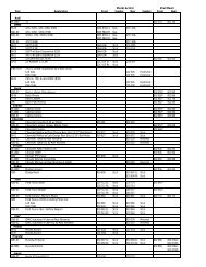
E46 M3 Diagnostic Socket: For model year<br />
2001 the E46 will eliminate the 20 pin diagnostic<br />
connector from the engine compartment.<br />
The 16 pin OBD II connector located inside the<br />
vehicle will be the only diagnosis port. The 16<br />
pin OBD II connector has been in all BMWs<br />
since 1996 to comply with OBD regulations<br />
requiring a standardized diagnostic port.<br />
Previously before 2001, only emissions relevant<br />
data could be extracted from the OBD connector<br />
because it did not provide access to TXD<br />
(D-bus). The TXD line is connected to pin 8 of<br />
the OBD II connector on vehicles without the 20<br />
pin diagnostic connector.<br />
124100109.jpg<br />
The cap to the OBD II connector contains a<br />
bridge that bridges KL 30 to TXD and TXD II.<br />
This is to protect the diagnostic circuit integrity<br />
and prevent erroneous faults from being logged.<br />
The OBD II connector is located in the drivers<br />
footwell to the left of the steering column.<br />
Special tool 61 4 300 is used to connect to the<br />
20 pin diagnostic lead of the DIS until the introduction<br />
of the DISplus.<br />
124100110.jpg<br />
Diagnostics via the<br />
OBD II Connector<br />
BMW DIS<br />
BMW DIS<br />
DIS/MoDiC<br />
CONNECTOR<br />
OBDII<br />
CONNECTOR<br />
16 987541<br />
TXD<br />
TXDI I<br />
KL31<br />
TD (RPM )<br />
- +<br />
KL30<br />
I/K-BUS<br />
IKE/KOMBI<br />
DME AGS<br />
KL15<br />
124100108.eps<br />
DSC<br />
80<br />
MS S54 Emissions Management
Workshop Hints<br />
Before any service work is performed on any fuel system<br />
related component, always adhere to the following:<br />
• Observe relevant safety legislation pertaining to your area.<br />
• Ensure adequate ventilation<br />
• Use exhaust extraction system where applicable (alleviate<br />
fumes).<br />
04410002<br />
• DO NOT SMOKE while performing fuel system repairs.<br />
• Always wear adequate protective clothing including eye protection.<br />
• Use caution when working around a HOT engine compartment.<br />
• BMW does not recommend any UNAUTHORIZED MODIFICATIONS to the fuel system.<br />
The fuel systems are designed to comply with strict federal safety and emissions<br />
regulations. In the concern of product liability, it is unauthorized to sell or perform modifications<br />
to customer vehicles, particularly in safety related areas.<br />
• Always consult the REPAIR INSTRUCTIONS on the specific model you are working<br />
on before attempting a repair.<br />
Checking Fuel Tank and Ventilation System for Leak-Tightness<br />
Refer to the Repair Information Section 16 00 100 for procedures on testing the fuel<br />
tank/ventilation system.<br />
Refer to Service Information Bulletins SI # 04 06 97 and # 04 01 98 for the special tools<br />
and adapters to perform the Evaporative Leakage Diagnosis Test.<br />
81<br />
MS S54 Emissions Management
Tools and Equipment<br />
The DISplus/Modic as well as a reputable hand<br />
held multimeter can be used when testing<br />
inputs/components.<br />
It is best to make the checks at the ECM connection,<br />
this method includes testing the wiring<br />
harness.<br />
07410001.eps<br />
The correct Universal Adapter for the MS S54<br />
application should be used (#90 88 6 121 300).<br />
This will ensure the pin connectors and the harness<br />
will not be damaged.<br />
When installing the Universal Adapter to the<br />
ECM (located in the Electronics Box in the<br />
engine compartment), make sure the ignition is<br />
switched off.<br />
13410063.eps<br />
When checking the fuel tank and ventilation<br />
system for leak-tightness use Special Tool Set<br />
#90 88 6 161 150 which includes all of the<br />
pieces shown to the right.<br />
This set is used in conjunction with shop supplied<br />
compressed air and the DISplus<br />
Multimeter function for reading the pressure<br />
bleed off.<br />
04410006.bmp<br />
82<br />
MS S54 Emissions Management
This Special Tool Set #90 88 6 161 160 will<br />
also be required to “cap off” the DM TL air filter<br />
and Evaporative Emission Valve hose when<br />
performing the Leakage Diagnosis Test.<br />
04400005.tiff<br />
If the test indicates excessive bleed off a leak<br />
detector should be used (refer to Repair<br />
Instructions) to check for leaks at:<br />
• Fuel Filler Cap and Filler Neck<br />
• Fuel Tank Ventilation Lines<br />
• Evaporative Emission Valve<br />
• Fuel Tank and Fuel Sending Unit<br />
• Liquid/Vapor Separator<br />
04410001.jpg<br />
83<br />
MS S54 Emissions Management
Performance Controls<br />
12410018.eps<br />
Sport Switch: The MS S54 ECM contains two different throttle<br />
progression program curves (Sport and Normal). The sport program<br />
is selected by pressing the Sport switch located in the center<br />
console switch panel.<br />
The switch provides a ground signal (input) to the ECM when<br />
pressed. The MS S54 activates the sport characteristics for the<br />
EDR throttle control. This provides an increase in throttle opening<br />
and response time over the non-sport position.<br />
12410019.eps<br />
Power Transmission Switch: The power transmission switch (circuit) consists of two<br />
switches in series. The circuit includes a clutch switch and a gear selector switch on the<br />
transmission. The functions of the power transmission switch are as follows:<br />
• Cutout for cruise control operation<br />
• Enable condition for idle control<br />
The switches provide a high signal for the MS S54 when the clutch is disengaged and the<br />
transmission is in gear. If either the clutch is engaged or the transmission is in neutral, the<br />
cruise control will be disengaged.<br />
84<br />
MS S54 Performance Controls<br />
12410051.eps
Cruise Control: As with other electronic throttle<br />
systems, the MS S54 ECM takes over the<br />
function of cruise control. Throttle activation is<br />
provided by the MS S54 electronic control of<br />
the EDR Actuator and monitoring of the feedback<br />
potentiometers.<br />
All driver requested cruise control function<br />
requests are provided to the MS S54 from the<br />
MFL II control module in the steering wheel<br />
over a single FGR data lead.<br />
31410001.jpg<br />
Oil Temperature/Level Sensor: The electronic level sensor is located in the engine sump<br />
mounted to the engine oil pan. The probe of the level sensor contains two temperature<br />
sensing elements.<br />
• One senses the engine oil temperature.<br />
• The other is heated to 10º C above the temperature<br />
of the engine and then is allowed to cool.<br />
The length of time it takes to cool the heated element<br />
is how the sensor determines the engine oil level.<br />
When the oil level is high it covers a larger portion of<br />
the probe submersed in the oil sump. The engine oil<br />
around the probe absorbs the heat of the heated element<br />
quicker than if the level is low.<br />
The microprocessor in the base of the sensor produces<br />
a pulse width modulated signal proportional to<br />
the oil level. The pulse width increases with a<br />
decreased level of oil.<br />
MONITORS ENGINE<br />
OIL TEMPERATURE<br />
FOR CALCULATION<br />
12410050.eps<br />
HEATED TO 10 C<br />
ABOVE OIL TEMP AND<br />
TIMED AS IT COOLS<br />
HIGH LEVEL:<br />
NARROW WIDE PULSE<br />
WIDTH<br />
LOW LEVEL:<br />
NARROW PULSE<br />
WIDTH<br />
Based on the oil temperature, the visual warning LEDs in the tachometer will illuminate at<br />
cold engine start up and slowly be extinguished as the oil temperature increases. One<br />
amber and the red LEDs always stay illuminated reminding the driver of maximum rpm<br />
zone.<br />
The oil temp sensor also serves as a vital input for VANOS operation, varying the solenoid<br />
control based on oil temperature (reaction time of camshaft movement). In the event of a<br />
fault the engine coolant temperature is used as a substitute value.<br />
85<br />
MS S54 Performance Controls
Electric Cooling Fan: The electric cooling fan is controlled by the ECM. The ECM uses a<br />
remote power output final stage (mounted on the fan housing). The power output stage<br />
receives power from a 50 amp fuse. The electric fan is controlled by a pulse width modulated<br />
signal from the ECM.<br />
The fan is activated based on the ECM calculation of:<br />
• Coolant outlet temperature (monitored by the Radiator Outlet Temperature Sensor)<br />
• Calculated (by the ECM) catalyst temperature<br />
• Vehicle speed<br />
• Battery voltage<br />
• Air Conditioning refrigerant pressure (calculated by IHKA and sent via the K-Bus to the<br />
ECM)<br />
12410009.bmp[<br />
86<br />
MS S54 Performance Controls
Workshop Hints<br />
IMPORTANT!<br />
From December 2001production, M3 and M roadster/coupe vehicles with S54 engines are<br />
delivered to the centers with the engine speed electronically limited to 5500 rpm as a transportation<br />
protection feature.<br />
During the pre-delivery inspection the engine speed limiter function has to be disabled using<br />
DISplus or MoDIC loaded with CD28.0 or higher. Refer to SI 12 01 02 for additional details.<br />
Procedure<br />
• Perform a “short test” on the ECM (DME) only<br />
• Select “Control Units Functions” path<br />
• Select “Digital Motor Electronics DME”<br />
• Select “Acknowledge Handover Inspection”<br />
• Select “Activate”<br />
• The display will show “off: terminate”<br />
Tools and Equipment<br />
The DISplus/MoDIC as well as a reputable hand<br />
held multimeter can be used when testing<br />
inputs/components.<br />
07410000.eps<br />
It is best to make the checks at the ECM connection,<br />
this method includes testing the wiring<br />
harness.<br />
The correct Universal Adapter for the MS S54<br />
application should be used (#90 88 6 121 300).<br />
This will ensure the pin connectors and the harness<br />
will not be damaged.<br />
When installing the Universal Adapter to the<br />
ECM (located in the Electronics Box in the<br />
engine compartment), make sure the ignition is<br />
switched off.<br />
13410063.eps<br />
87<br />
MS S54 Performance Controls
Review Questions<br />
1. Describe the Power Supply for the Fuel Injectors and Ignition Coils:________________<br />
__________________________________________________________________________<br />
__________________________________________________________________________<br />
__________________________________________________________________________<br />
__________________________________________________________________________<br />
2. Name the Components of the Fuel Supply System:<br />
________________ _______________ _______________<br />
________________ _______________ _______________<br />
3. List the inputs required fpr Fuel Injector operation:<br />
________________ _______________ _______________<br />
________________ _______________ _______________<br />
4. Describe the Emission Optimized Function:_____________________________________<br />
__________________________________________________________________________<br />
__________________________________________________________________________<br />
__________________________________________________________________________<br />
5. Name two types of Emissions the ECM controls:______________ ______________<br />
6. What two sensors are used to monitor throttle movement?<br />
______________________ ______________________<br />
7. Why are there two inputs from the Accelerator Module?__________________________<br />
__________________________________________________________________________<br />
__________________________________________________________________________<br />
8. Where is the Diagnostic Socket located? ______________________________________<br />
9. How many speeds will the Secondary Air Injection Pump run at?__________________<br />
10. What is the Repair Instruction (number) for the procedure to perform a Leakage<br />
Diagnosis Test?___________________________________________________________<br />
11. How is the secondary ignition monitored for misfire?____________________________<br />
_________________________________________________________________________<br />
_________________________________________________________________________<br />
88<br />
MS S54 Performance Controls