Modeling and System-level Simulation of Force-balance MEMS ...
Modeling and System-level Simulation of Force-balance MEMS ...
Modeling and System-level Simulation of Force-balance MEMS ...

Create successful ePaper yourself
Turn your PDF publications into a flip-book with our unique Google optimized e-Paper software.
2.2. Interface Electronics<br />
Sensors & Transducers Journal, Vol. 127, Issue 4, April 2011, pp. 88-101<br />
n order to measure the capacitance change, it’s not only to apply the excitation signal on the sense<br />
element, but also need to pick up signals from it for subsequent conditioning circuit’s processing. The<br />
excitation signal can be either a voltage or current signal, <strong>and</strong> also are the picked signals. When using<br />
the current signal as the excitation signal, the magnitude <strong>of</strong> the current signal through the sense<br />
element is determined by the admittance <strong>of</strong> the excitation node, which means it’s related to the<br />
magnitude <strong>of</strong> the parasitic capacitance. Hence, it’s better to use the voltage signal as the excitation<br />
signal. If the picked signals are voltage signal, it’s also affected by the parasitic capacitance, so it’s<br />
more <strong>of</strong>ten used to pick up current signals from the sense element. To sum up, it’s a suitable way to use<br />
a voltage signal to excite the sense element <strong>and</strong> pick up current signals from it.<br />
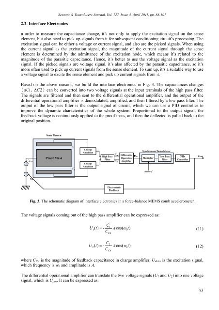
Based on the above reasons, we build the interface electronics in Fig. 3. The capacitances changes<br />
( C1, C2<br />
) can be converted into two voltage signals at the input terminals <strong>of</strong> the high pass filter.<br />
The signals are filtered <strong>and</strong> then sent to the differential operational amplifier, <strong>and</strong> the output <strong>of</strong> the<br />
differential operational amplifier is demodulated, amplified, <strong>and</strong> then filtered by a low pass filter. The<br />
output <strong>of</strong> the low pass filter is the output signal <strong>of</strong> circuit, which we can use a PID controller to<br />
improve the dynamic characteristics <strong>of</strong> the whole system. Proportional to the output signal, the<br />
feedback voltage is continuously applied to the pro<strong>of</strong> mass, <strong>and</strong> then the deflected is pulled back to the<br />
original position.<br />
C 1<br />
U drive<br />
C 2<br />
Fig. 3. The schematic diagram <strong>of</strong> interface electronics in a force-<strong>balance</strong> <strong>MEMS</strong> comb accelerometer.<br />
The voltage signals coming out <strong>of</strong> the high pass amplifier can be expressed as:<br />
C<br />
U () t - Acos( t)<br />
(11)<br />
1<br />
1 0<br />
CCA<br />
C<br />
U () t - Acos( w t)<br />
(12)<br />
2<br />
2 0<br />
CCA<br />
where C CA is the magnitude <strong>of</strong> feedback capacitance in charge amplifier; U drive is the excitation signal,<br />
which frequency is w 0 <strong>and</strong> amplitude is A.<br />
The differential operational amplifier can translate the two voltage signals (U 1 <strong>and</strong> U 2 ) into one voltage<br />
signal, which is U pos . It can be expressed as:<br />
93