Modeling and System-level Simulation of Force-balance MEMS ...
Modeling and System-level Simulation of Force-balance MEMS ...
Modeling and System-level Simulation of Force-balance MEMS ...

You also want an ePaper? Increase the reach of your titles
YUMPU automatically turns print PDFs into web optimized ePapers that Google loves.
Sensors & Transducers Journal, Vol. 127, Issue 4, April 2011, pp. 88-101<br />
element <strong>and</strong> interface electronics. <strong>Simulation</strong> results are obtained from COVENTOR <strong>and</strong> MATLAB in<br />
Section III. The conclusions are reported in Section IV.<br />
2. Theoretical Principles <strong>of</strong> <strong>MEMS</strong> Comb Accelerometers<br />
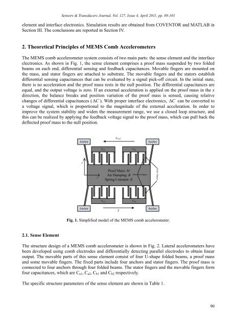
The <strong>MEMS</strong> comb accelerometer system consists <strong>of</strong> two main parts: the sense element <strong>and</strong> the interface<br />
electronics. As shown in Fig. 1, the sense element comprises a pro<strong>of</strong> mass suspended by two folded<br />
beams on each end, differential sensing <strong>and</strong> feedback capacitances. Movable fingers are mounted on<br />
the mass, <strong>and</strong> stator fingers are attached to substrate. The movable fingers <strong>and</strong> the stators establish<br />
differential sensing capacitances that can be evaluated by a signal pick-<strong>of</strong>f circuit. In the initial state,<br />
there is no acceleration <strong>and</strong> the pro<strong>of</strong> mass rests in the null position. The differential capacitances are<br />
equal, <strong>and</strong> the output voltage is zero. If an external acceleration is applied on the pro<strong>of</strong> mass in the x<br />
direction, the <strong>balance</strong> breaks <strong>and</strong> position variation <strong>of</strong> the pro<strong>of</strong> mass is sensed, causing relative<br />
changes <strong>of</strong> differential capacitances ( C ). With proper interface electronics, C can be converted to<br />
a voltage signal, which is proportional to the magnitude <strong>of</strong> the external acceleration. In order to<br />
improve the system stability <strong>and</strong> widen the measurement range, we use a closed loop structure, <strong>and</strong><br />
this can be realized by applying the feedback voltage signal to the pro<strong>of</strong> mass, which can pull back the<br />
deflected pro<strong>of</strong> mass to the null position.<br />
Anchor<br />
F EXT<br />
Anchor<br />
C a1<br />
C b1<br />
y<br />
x<br />
Pro<strong>of</strong> Mass: M<br />
Air Damping: B<br />
Spring Constant: K<br />
Movable fingers<br />
Stator fingers<br />
C a2<br />
C b2<br />
Anchor<br />
X<br />
Anchor<br />
Fig. 1. Simplified model <strong>of</strong> the <strong>MEMS</strong> comb accelerometer.<br />
2.1. Sense Element<br />
The structure design <strong>of</strong> a <strong>MEMS</strong> comb accelerometer is shown in Fig. 2. Lateral accelerometers have<br />
been developed using comb electrodes <strong>and</strong> differentially detecting parallel electrodes to obtain linear<br />
output. The movable parts <strong>of</strong> this sense element consist <strong>of</strong> four U-shape folded beams, a pro<strong>of</strong> mass<br />
<strong>and</strong> some movable fingers. The fixed parts include four anchors <strong>and</strong> stator fingers. The pro<strong>of</strong> mass is<br />
connected to four anchors through four folded beams. The stator fingers <strong>and</strong> the movable fingers form<br />
four capacitances, which are C a1 , C a2 , C b1 <strong>and</strong> C b2 respectively.<br />
The specific structure parameters <strong>of</strong> the sense element are shown in Table 1.<br />
90