GTX 4-TEC /Supercharged - Sea-Doo.net
GTX 4-TEC /Supercharged - Sea-Doo.net
GTX 4-TEC /Supercharged - Sea-Doo.net

Create successful ePaper yourself
Turn your PDF publications into a flip-book with our unique Google optimized e-Paper software.
2004<br />
Shop Manual<br />
GTI, GTI LE, GTI RFI, GTI LE RFI, XP DI<br />
<strong>GTX</strong> 4-<strong>TEC</strong> /<strong>Supercharged</strong> /Limited <strong>Supercharged</strong> /Wakeboard Edition<br />
RXP 4-<strong>TEC</strong> <strong>Supercharged</strong><br />
BOMBARDIER RECREATIONAL PRODUCTS INC.
Legal deposit:<br />
National Library of Quebec<br />
National Library of Canada 2004<br />
All rights reserved. No parts of this manual may be reproduced in any form without the prior written<br />
permission of Bombardier Recreational Products Inc.<br />
©Bombardier Recreational Products Inc. 2004<br />
Technical Publications<br />
Bombardier Recreational Products Inc.<br />
Valcourt (Quebec) Canada<br />
PrintedinCanada<br />
®TMRegistered trademarks of Bombardier Recreational Products Inc. or its affiliates.<br />
† Bombardier and sprocket design are trademarks of Bombardier Inc, used under license.<br />
SEA-DOO ®<br />
BOMBARDIER-ROTAX ®<br />
BOMBARDIER LUBE ®<br />
BOMBARDIER-ROTAX Formula XP-S Synthetic Injection<br />
Oil BOMBARDIER Formula XP-S DI Synthetic Injection Oil<br />
BOMBARDIER-ROTAX Injection Oil<br />
<strong>Sea</strong>-<strong>Doo</strong> Synthetic Grease<br />
<strong>Sea</strong>-<strong>Doo</strong> LK TM<br />
DESS TM<br />
Rotax ®<br />
O.P.A.S. TM<br />
TOPS TM<br />
This document contains the trademarks of the following companies:<br />
Knight’s Spray-Nine † is a trademark of Korkay System Ltd<br />
<strong>GTX</strong> † is a trademark of Castrol Ltd. Used under license<br />
Loctite ® is a trademark of Loctite Corporation<br />
Snap-on ® is a trademark of Snap-on Tools Corporation<br />
Gelcote ® is a trademark of Gelcote International Limited<br />
Molykote © is a trademark of Dow Corning Corporation<br />
Snap-on © is a trademark of Snap-on Tools Corporation<br />
AMP © is a trademark of Tyco Electronics Corporation
TABLE OF CONTENTS<br />
SAFETY NOTICE..................................................................................<br />
XII<br />
INTRODUCTION .................................................................................. XIII<br />
HULL IDENTIFICATION NUMBER (H.I.N.) ..................................................................... XIII<br />
ENGINE IDENTIFICATION NUMBER (E.I.N.) .................................................................. XIV<br />
ARRANGEMENT OF THIS MANUAL........................................................................... XV<br />
LIST OF ABBREVIATIONS USED IN THIS MANUAL....................................................... XVIII<br />
GENERAL INFORMATION...................................................................................... XVIII<br />
ILLUSTRATIONS AND PROCEDURES ......................................................................... XIX<br />
ENGINE EMISSIONS INFORMATION .......................................................................... XIX<br />
SELF-LOCKING FASTENERS PROCEDURE ................................................................... XX<br />
LOCTITE APPLICATION PROCEDURE.......................................................................... XX<br />
THREADLOCKER .................................................................................................. XX<br />
STRIPPED THREAD REPAIR ..................................................................................... XXI<br />
GASKET COMPOUND........................................................................................... XXII<br />
MOUNTING ON SHAFT ......................................................................................... XXII<br />
CASE-IN COMPONENTS....................................................................................... XXIII<br />
TIGHTENING TORQUES ....................................................................................... XXIV<br />
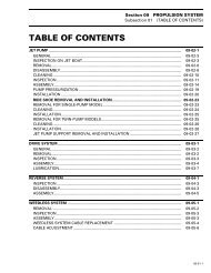
01 SERVICE TOOLS AND PRODUCTS<br />
01 – MANDATORY SERVICE TOOLS ............................................................................. 1<br />
ENGINE ................................................................................................................ 1<br />
COOLING/FUEL/OIL SYSTEMS...................................................................................... 5<br />
PROPULSION SYSTEM............................................................................................... 6<br />
STEERING SYSTEM................................................................................................... 8<br />
02 – OPTIONAL SERVICE TOOLS ................................................................................ 9<br />
ENGINE ................................................................................................................ 9<br />
COOLING/FUEL/OIL SYSTEMS..................................................................................... 14<br />
PROPULSION SYSTEM.............................................................................................. 14<br />
BODY.................................................................................................................. 15<br />
WATERCRAFT HANDLING .......................................................................................... 15<br />
03 – SERVICE PRODUCTS ....................................................................................... 17<br />
02 MAINTENANCE<br />
01 – PERIODIC INSPECTION CHART............................................................................ 21<br />
02 – FLUSHING AND LUBRICATION............................................................................ 27<br />
GENERAL............................................................................................................. 27<br />
PROCEDURE ......................................................................................................... 27<br />
ANTICORROSION TREATMENT.................................................................................... 32<br />
03 – WATER-FLOODED ENGINE................................................................................. 33<br />
GENERAL............................................................................................................. 33<br />
PROCEDURE ......................................................................................................... 33<br />
04 – STORAGE ..................................................................................................... 39<br />
ENGINE DRAINING .................................................................................................. 39<br />
PROPULSION SYSTEM.............................................................................................. 40<br />
FUEL SYSTEM........................................................................................................ 41<br />
ENGINE OIL CHANGE AND FILTER ................................................................................ 41<br />
COOLING SYSTEM FLUSHING AND ENGINE INTERNAL LUBRICATION ...................................... 41<br />
ENGINE LUBRICATION.............................................................................................. 41<br />
BATTERY.............................................................................................................. 42<br />
WATERCRAFT CLEANING........................................................................................... 42<br />
ADDITIONAL RECOMMENDED PRO<strong>TEC</strong>TION ................................................................... 42<br />
I
TABLE OF CONTENTS<br />
ANTICORROSION TREATMENT.................................................................................... 48<br />
CHECKLIST........................................................................................................... 48<br />
03 TROUBLESHOOTING<br />
01 – TROUBLESHOOTING CHART.............................................................................. 49<br />
ENGINE WILL NOT START.......................................................................................... 49<br />
ENGINE HARD TO START........................................................................................... 52<br />
ENGINE STARTS BUT RUNS ONLY AT IDLE SPEED.............................................................. 52<br />
ENGINE MISFIRES, RUNS IRREGULARLY......................................................................... 53<br />
ENGINE CONTINUALLY BACKFIRES............................................................................... 55<br />
ENGINE DETONATION OR PINGING............................................................................... 55<br />
ENGINE LACKS ACCELERATION OR POWER .................................................................... 56<br />
ENGINE STOPS RUNNING .......................................................................................... 57<br />
ENGINE CANNOT REACH MAXIMUM RPM ...................................................................... 57<br />
ENGINE RUNS TOO FAST (VEHICLE CANNOT REACH ITS TOP SPEED)....................................... 58<br />
ENGINE OVERHEATS................................................................................................ 58<br />
O.P.A.S. SYSTEM FAULTS (<strong>GTX</strong> 4-<strong>TEC</strong> MODELS)................................................................. 59<br />
ENGINE SMOKE IN THE EXHAUST (4-<strong>TEC</strong> SERIES).............................................................. 59<br />
LOW OR NO ENGINE OIL PRESSURE (4-<strong>TEC</strong> SERIES) .......................................................... 60<br />
ENGINE OIL CONTAMINATION (MILKY) (4-<strong>TEC</strong> SERIES) ........................................................ 60<br />
UNUSUAL ENGINE NOISE AND/OR VIBRATION (4-<strong>TEC</strong> SERIES) ............................................... 61<br />
ABNORMAL NOISE FROM PROPULSION SYSTEM.............................................................. 61<br />
04 ENGINE (2-STROKE)<br />
01 – LEAK TEST .................................................................................................... 63<br />
GENERAL............................................................................................................. 63<br />
PREPARATION ....................................................................................................... 63<br />
TESTING PROCEDURE.............................................................................................. 63<br />
ENGINE LEAKAGE DIAGNOSTIC FLOW CHART.................................................................. 69<br />
02 – REMOVAL AND INSTALLATION........................................................................... 71<br />
GENERAL............................................................................................................. 71<br />
ENGINE REMOVAL .................................................................................................. 71<br />
CLEANING............................................................................................................ 76<br />
INSTALLATION ....................................................................................................... 76<br />
03 – MAGNETO SYSTEM......................................................................................... 83<br />
DISASSEMBLY ....................................................................................................... 86<br />
CLEANING............................................................................................................ 93<br />
ASSEMBLY ........................................................................................................... 93<br />
04 – TOP END....................................................................................................... 99<br />
GENERAL........................................................................................................... 102<br />
DISASSEMBLY ..................................................................................................... 104<br />
CLEANING.......................................................................................................... 111<br />
INSPECTION........................................................................................................ 112<br />
USED PISTON MEASUREMENT.................................................................................. 113<br />
ASSEMBLY ......................................................................................................... 116<br />
ADJUSTMENT...................................................................................................... 125<br />
05 – BOTTOM END ............................................................................................... 129<br />
DISASSEMBLY ..................................................................................................... 132<br />
CLEANING.......................................................................................................... 139<br />
INSPECTION........................................................................................................ 140<br />
ASSEMBLY ......................................................................................................... 144<br />
II
TABLE OF CONTENTS<br />
06 – ROTARY VALVE ............................................................................................. 153<br />
GENERAL........................................................................................................... 154<br />
INSPECTION ON WATERCRAFT.................................................................................. 154<br />
DISASSEMBLY ..................................................................................................... 155<br />
CLEANING.......................................................................................................... 157<br />
INSPECTION........................................................................................................ 157<br />
ASSEMBLY ......................................................................................................... 158<br />
ROTARY VALVE TIMING........................................................................................... 162<br />
07 – EXHAUST SYSTEM......................................................................................... 165<br />
REMOVAL .......................................................................................................... 168<br />
TUNED PIPE REPAIR .............................................................................................. 174<br />
INSTALLATION ..................................................................................................... 174<br />
05 ENGINE (4-<strong>TEC</strong>)<br />
01 – LEAK TEST ................................................................................................... 181<br />
LEAK TEST PROCEDURE .................................................................................. 181<br />
PREPARATION ..................................................................................................... 181<br />
PROCEDURE ....................................................................................................... 182<br />
INSTALLATION ..................................................................................................... 183<br />
LEAK TEST PROCEDURE FOR INTERCOOLER......................................................... 184<br />
02 – INTAKE SYSTEM............................................................................................ 185<br />
INSPECTION........................................................................................................ 189<br />
REMOVAL .......................................................................................................... 191<br />
DISASSEMBLY ..................................................................................................... 198<br />
ASSEMBLY ......................................................................................................... 201<br />
INSTALLATION ..................................................................................................... 205<br />
03 – EXHAUST SYSTEM......................................................................................... 209<br />
EXHAUST PIPE..................................................................................................... 210<br />
EXHAUST MANIFOLD............................................................................................. 213<br />
MUFFLER........................................................................................................... 214<br />
RESONATOR ....................................................................................................... 214<br />
EXHAUST OUTLET................................................................................................. 215<br />
04 – REMOVAL AND INSTALLATION.......................................................................... 217<br />
GENERAL........................................................................................................... 217<br />
ENGINE REMOVAL ................................................................................................ 217<br />
CLEANING.......................................................................................................... 221<br />
INSTALLATION ..................................................................................................... 221<br />
05 – PTO HOUSING/MAGNETO................................................................................ 225<br />
GENERAL........................................................................................................... 226<br />
PTO HOUSING ..................................................................................................... 226<br />
PTO SEAL........................................................................................................... 229<br />
COUPLING.......................................................................................................... 229<br />
STATOR............................................................................................................. 230<br />
ROTOR AND ENCODER WHEEL................................................................................. 231<br />
RING GEAR......................................................................................................... 231<br />
STARTER DRIVE ASS'Y............................................................................................ 232<br />
OIL SPRAY NOZZLE ............................................................................................... 233<br />
06 – LUBRICATION SYSTEM.................................................................................... 235<br />
GENERAL........................................................................................................... 237<br />
OIL LEVEL VERIFICATION......................................................................................... 237<br />
ENGINE OIL PRESSURE TEST.................................................................................... 238<br />
OIL FILTER.......................................................................................................... 240<br />
III
TABLE OF CONTENTS<br />
OIL STRAINERS.................................................................................................... 241<br />
ENGINE OIL PRESSURE REGULATOR........................................................................... 244<br />
OIL PRESSURE PUMP............................................................................................. 245<br />
OIL SUCTION PUMP............................................................................................... 248<br />
OIL COOLER ....................................................................................................... 251<br />
OIL SEPARATOR ................................................................................................... 252<br />
07 – CYLINDER HEAD AND VALVES........................................................................... 255<br />
GENERAL........................................................................................................... 256<br />
SPARK PLUG ....................................................................................................... 256<br />
VALVE COVER...................................................................................................... 256<br />
ROCKER ARM...................................................................................................... 257<br />
CAMSHAFT TIMING GEAR........................................................................................ 260<br />
TIMING CHAIN..................................................................................................... 262<br />
CYLINDER HEAD................................................................................................... 262<br />
CAMSHAFT......................................................................................................... 263<br />
VALVE SPRING ..................................................................................................... 265<br />
VALVE ............................................................................................................... 266<br />
08 – ENGINE BLOCK.............................................................................................. 273<br />
GENERAL........................................................................................................... 275<br />
CRANKSHAFT LOCKING .......................................................................................... 275<br />
CRANKSHAFT ...................................................................................................... 275<br />
TIMING CHAIN..................................................................................................... 279<br />
CHAIN TENSIONER................................................................................................ 280<br />
BALANCER SHAFT................................................................................................. 280<br />
ENGINE BLOCK.................................................................................................... 283<br />
PISTON/CONNECTING ROD...................................................................................... 288<br />
PISTON RINGS ..................................................................................................... 294<br />
06 ENGINE MANAGEMENT (RFI)<br />
01 – OVERVIEW................................................................................................... 297<br />
AIR INDUCTION............................................................................................. 298<br />
FUEL DELIVERY ............................................................................................. 298<br />
FUEL PUMP ........................................................................................................ 298<br />
FUEL PRESSURE REGULATOR................................................................................... 298<br />
FUEL FILTERS...................................................................................................... 298<br />
FUEL PUMP MODULE ............................................................................................ 299<br />
FUEL INJECTORS.................................................................................................. 299<br />
ELECTRONIC MANAGEMENT ............................................................................ 299<br />
ELECTRONIC CONTROL UNIT (ECU) ............................................................................ 299<br />
MPEM (MULTI-PURPOSE ELECTRONIC MODULE)............................................................ 300<br />
02 – DIAGNOSTIC PROCEDURES ............................................................................. 303<br />
INTRODUCTION.................................................................................................... 303<br />
SELF-DIAGNOSTIC MODE........................................................................................ 303<br />
ADVANCED DIAGNOSTIC......................................................................................... 303<br />
FAULT CODE TABLES ............................................................................................. 305<br />
03 – COMPONENT INSPECTION .............................................................................. 307<br />
GENERAL..................................................................................................... 307<br />
AIR INDUCTION SYSTEM ................................................................................. 309<br />
THROTTLE BODY .................................................................................................. 309<br />
FUEL DELIVERY ............................................................................................. 309<br />
FUEL FILTER........................................................................................................ 309<br />
FUEL PUMP ........................................................................................................ 309<br />
IV
TABLE OF CONTENTS<br />
REGULATOR........................................................................................................ 309<br />
FUEL INJECTOR ................................................................................................... 310<br />
LEAK TEST (SUPPLY AND VENTILATION CIRCUITS) ........................................................... 311<br />
HIGH PRESSURE TEST (FUEL PUMP CIRCUIT)................................................................. 311<br />
ELECTRONIC MANAGEMENT ............................................................................ 312<br />
THROTTLE POSITION SENSOR (TPS)............................................................................ 312<br />
CRANKSHAFT POSITION SENSOR (CPS)........................................................................ 313<br />
AIR TEMPERATURE SENSOR (ATS).............................................................................. 314<br />
WATER TEMPERATURE SENSOR (WTS) ........................................................................ 314<br />
AIR PRESSURE SENSOR (APS)................................................................................... 315<br />
RAVE SOLENOID................................................................................................... 316<br />
RFI SENSORS RESISTANCE VALUES............................................................................ 317<br />
04 – TROUBLESHOOTING SUMMARY........................................................................ 319<br />
ENGINE DOES NOT START ............................................................................... 319<br />
FLOODED ENGINE FEATURE ............................................................................. 319<br />
SPARK PLUG INSPECTION................................................................................ 319<br />
ECU FAULT CODES......................................................................................... 319<br />
ENGINE STARTS BUT RUNS POORLY .................................................................. 319<br />
ENGINE RUNS ONLY ON ONE CYLINDER.............................................................. 319<br />
ENGINE CANNOT REACH MAXIMUM REVOLUTIONS............................................... 320<br />
05 – ADJUSTMENT............................................................................................... 321<br />
THROTTLE CABLE ADJUSTMENT....................................................................... 321<br />
THROTTLE POSITION SENSOR (TPS)................................................................... 321<br />
CLOSED TPS ....................................................................................................... 321<br />
IDLE SPEED ........................................................................................................ 321<br />
06 – REMOVAL AND INSTALLATION ......................................................................... 323<br />
MPEM/ECU................................................................................................... 323<br />
THROTTLE POSITION SENSOR (TPS)................................................................... 323<br />
AIR TEMPERATURE SENSOR (ATS) ..................................................................... 323<br />
AIR PRESSURE SENSOR (APS)........................................................................... 323<br />
WATER TEMPERATURE SENSOR (WTS) ............................................................... 323<br />
CRANKSHAFT POSITION SENSOR (CPS) .............................................................. 323<br />
FUEL PUMP ASSEMBLY................................................................................... 323<br />
REGULATOR........................................................................................................ 324<br />
FUEL FILTER........................................................................................................ 324<br />
FUEL INJECTORS........................................................................................... 324<br />
07 ENGINE MANAGEMENT (DI)<br />
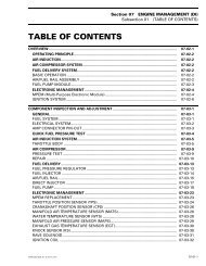
01 – OVERVIEW................................................................................................... 327<br />
OPERATING PRINCIPLE.................................................................................... 327<br />
AIR INDUCTION............................................................................................. 327<br />
AIR COMPRESSOR SYSTEM.............................................................................. 327<br />
FUEL DELIVERY SYSTEM.................................................................................. 327<br />
BASIC OPERATION ................................................................................................ 327<br />
AIR/FUEL RAIL ASSEMBLY ....................................................................................... 328<br />
FUEL PUMP MODULE ............................................................................................ 328<br />
ELECTRONIC MANAGEMENT ............................................................................ 329<br />
MPEM (MULTI-PURPOSE ELECTRONIC MODULE)............................................................ 329<br />
MPEM — ENGINE MANAGEMENT FUNCTIONS............................................................... 332<br />
IGNITION SYSTEM................................................................................................. 334<br />
02 – COMPONENT INSPECTION AND ADJUSTMENT ..................................................... 335<br />
GENERAL..................................................................................................... 335<br />
V
TABLE OF CONTENTS<br />
FUEL SYSTEM...................................................................................................... 335<br />
ELECTRICAL SYSTEM............................................................................................. 336<br />
AMP CONNECTOR PIN-OUT...................................................................................... 337<br />
QUICK FUEL PRESSURE TEST ........................................................................... 337<br />
AIR INDUCTION SYSTEM ................................................................................. 339<br />
THROTTLE BODY .................................................................................................. 339<br />
AIR COMPRESSOR ......................................................................................... 342<br />
PRESSURE TEST................................................................................................... 342<br />
REPAIR.............................................................................................................. 343<br />
FUEL DELIVERY ............................................................................................. 346<br />
FUEL PRESSURE REGULATOR................................................................................... 346<br />
FUEL INJECTOR ................................................................................................... 348<br />
AIR/FUEL RAIL ..................................................................................................... 349<br />
DIRECT INJECTOR................................................................................................. 350<br />
FUEL PUMP ........................................................................................................ 352<br />
FUEL FILTERS ..................................................................................................... 354<br />
ELECTRONIC MANAGEMENT ............................................................................ 357<br />
MPEM REPLACEMENT ........................................................................................... 357<br />
THROTTLE POSITION SENSOR (TPS)............................................................................ 358<br />
CRANKSHAFT POSITION SENSOR (CPS)........................................................................ 360<br />
MANIFOLD AIR TEMPERATURE SENSOR (MATS) ............................................................. 362<br />
WATER TEMPERATURE SENSOR (WTS) ........................................................................ 362<br />
MANIFOLD AIR PRESSURE SENSOR (MAPS) .................................................................. 363<br />
EXHAUST GAS TEMPERATURE SENSOR (EGTS)............................................................... 364<br />
KNOCK SENSOR (KS).............................................................................................. 364<br />
RAVE SOLENOID................................................................................................... 365<br />
IGNITION COIL..................................................................................................... 366<br />
IGNITION TIMING.................................................................................................. 368<br />
SPARK PLUGS...................................................................................................... 372<br />
CRANKING SYSTEM ............................................................................................... 373<br />
DI SYSTEM TEST SUMMARY..................................................................................... 373<br />
03 – DIAGNOSTIC PROCEDURES.............................................................................. 377<br />
GENERAL..................................................................................................... 377<br />
FAULT DE<strong>TEC</strong>TION AND COMPENSATORY ACTIONS............................................... 379<br />
COMPONENT FAILURE WARNING SYSTEM.................................................................... 379<br />
VCK (VEHICLE COMMUNICATION KIT) ................................................................. 381<br />
DI SYSTEM FAULT CODES................................................................................ 382<br />
08 ENGINE MANAGEMENT (4-<strong>TEC</strong>)<br />
01 – OVERVIEW................................................................................................... 391<br />
COMPLETE ELECTRICAL SYSTEM OVERVIEW ........................................................ 391<br />
MAGNETO SYSTEM AND POWER SUPPLY............................................................ 393<br />
OPERATING PRINCIPLE OF ENGINE MANAGEMENT ................................................ 393<br />
AIR INDUCTION............................................................................................. 393<br />
FUEL DELIVERY SYSTEM.................................................................................. 394<br />
BASIC OPERATION ................................................................................................ 394<br />
FUEL PUMP MODULE ............................................................................................ 396<br />
ELECTRONIC MANAGEMENT ............................................................................ 396<br />
EMS (ENGINE MANAGEMENT SYSTEM)........................................................................ 396<br />
EMS — GENERAL FUNCTIONS .................................................................................. 397<br />
EMS — ENGINE MANAGEMENT FUNCTIONS ................................................................. 399<br />
MPEM — MULTI-PURPOSE ELECTRONIC MODULE .......................................................... 402<br />
VI
TABLE OF CONTENTS<br />
02 – COMPONENT INSPECTION AND ADJUSTMENT ..................................................... 403<br />
GENERAL..................................................................................................... 403<br />
FUEL SYSTEM...................................................................................................... 403<br />
ELECTRICAL SYSTEM............................................................................................. 404<br />
ENGINE CONNECTOR PIN-OUT.................................................................................. 405<br />
CONNECTORS ON ENGINE....................................................................................... 406<br />
AIR INDUCTION SYSTEM ................................................................................. 407<br />
THROTTLE BODY .................................................................................................. 407<br />
FUEL DELIVERY ............................................................................................. 411<br />
FUEL PUMP ........................................................................................................ 412<br />
FUEL FILTER ....................................................................................................... 414<br />
FUEL RAIL .......................................................................................................... 414<br />
FUEL INJECTOR ................................................................................................... 415<br />
ELECTRONIC MANAGEMENT ............................................................................ 417<br />
ECM AND MPEM REPLACEMENT .............................................................................. 417<br />
ENGINE WIRING HARNESS....................................................................................... 419<br />
THROTTLE POSITION SENSOR (TPS)............................................................................ 421<br />
IDLE BYPASS VALVE............................................................................................... 423<br />
CRANKSHAFT POSITION SENSOR (CPS)........................................................................ 424<br />
CAMSHAFT POSITION SENSOR (CAPS)......................................................................... 425<br />
MANIFOLD AIR TEMPERATURE SENSOR (MATS) ............................................................. 426<br />
COOLANT TEMPERATURE SENSOR (CTS)...................................................................... 427<br />
MANIFOLD AIR PRESSURE SENSOR (MAPS) .................................................................. 428<br />
EXHAUST GAS TEMPERATURE SENSOR (EGTS)............................................................... 429<br />
KNOCK SENSOR (KS).............................................................................................. 429<br />
OIL PRESSURE SENSOR (OPS) .................................................................................. 431<br />
OIL SEPARATOR PRESSURE SENSOR (OSPS) ................................................................. 431<br />
TOPS VALVE (BLOW-BY).......................................................................................... 433<br />
IGNITION COILS ................................................................................................... 436<br />
IGNITION TIMING.................................................................................................. 437<br />
ENGINE START/STOP SWITCH VERIFICATION ................................................................. 437<br />
SAFETY LANYARD SWITCH VERIFICATION..................................................................... 437<br />
SPARK PLUGS...................................................................................................... 438<br />
CRANKING SYSTEM ............................................................................................... 438<br />
03 – DIAGNOSTIC PROCEDURES.............................................................................. 439<br />
GENERAL........................................................................................................... 439<br />
SELF-DIAGNOSTIC MODE................................................................................. 441<br />
VCK (VEHICLE COMMUNICATION KIT) ................................................................. 443<br />
4-<strong>TEC</strong> SYSTEM FAULT CODES ........................................................................... 444<br />
4-<strong>TEC</strong> SYSTEM FAULT CODES CHART .......................................................................... 447<br />
BURNT FUSE AND RELATED FAULT CODE..................................................................... 465<br />
09 COOLING SYSTEM<br />
01 – CIRCUIT, COMPONENTS AND CARE.................................................................... 467<br />
CIRCUIT............................................................................................................. 473<br />
COMPONENTS..................................................................................................... 476<br />
CARE ................................................................................................................ 480<br />
CIRCUIT............................................................................................................. 488<br />
COOLING SYSTEM LEAK TEST................................................................................... 488<br />
INSPECTION........................................................................................................ 490<br />
DRAINING THE SYSTEM.......................................................................................... 490<br />
CLEANING.......................................................................................................... 490<br />
VII
TABLE OF CONTENTS<br />
COOLANT REPLACEMENT ....................................................................................... 491<br />
COOLANT PUMP HOUSING...................................................................................... 492<br />
THERMOSTAT...................................................................................................... 493<br />
COOLANT PUMP IMPELLER ..................................................................................... 494<br />
ROTARY SEAL...................................................................................................... 494<br />
CARE ................................................................................................................ 496<br />
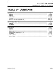
10 FUEL SYSTEM<br />
01 – FUEL CIRCUIT ............................................................................................... 499<br />
GENERAL........................................................................................................... 505<br />
REMOVAL .......................................................................................................... 506<br />
INSPECTION........................................................................................................ 508<br />
ASSEMBLY ......................................................................................................... 509<br />
FUEL SYSTEM PRESSURIZATION................................................................................ 509<br />
02 – AIR INTAKE (2-STROKE)................................................................................... 511<br />
GENERAL........................................................................................................... 513<br />
REMOVAL .......................................................................................................... 513<br />
ASSEMBLY ......................................................................................................... 514<br />
REMOVAL .......................................................................................................... 516<br />
ASSEMBLY ......................................................................................................... 517<br />
03 – CARBURETOR ............................................................................................... 519<br />
GENERAL........................................................................................................... 520<br />
REMOVAL .......................................................................................................... 520<br />
CLEANING.......................................................................................................... 520<br />
DISASSEMBLY AND INSPECTION ............................................................................... 521<br />
ASSEMBLY ......................................................................................................... 523<br />
INSTALLATION ..................................................................................................... 525<br />
ADJUSTMENTS.................................................................................................... 525<br />
11 LUBRICATION SYSTEM (2-STROKE)<br />
01 – OIL INJECTION SYSTEM .................................................................................. 529<br />
GENERAL........................................................................................................... 531<br />
OIL SYSTEM PRESSURIZATION.................................................................................. 531<br />
02 – OIL INJECTION PUMP...................................................................................... 533<br />
OIL PUMP IDENTIFICATION ...................................................................................... 536<br />
REMOVAL .......................................................................................................... 536<br />
DISASSEMBLY ..................................................................................................... 536<br />
CLEANING.......................................................................................................... 536<br />
ASSEMBLY ......................................................................................................... 536<br />
ADJUSTMENT...................................................................................................... 538<br />
CHECKING OPERATION........................................................................................... 541<br />
12 ELECTRICAL SYSTEM<br />
01 – IGNITION SYSTEM ......................................................................................... 543<br />
GENERAL........................................................................................................... 543<br />
MULTI-PURPOSE ELECTRONIC MODULE (MPEM)............................................................ 544<br />
IGNITION TIMING ................................................................................................. 544<br />
PROCEDURE ....................................................................................................... 552<br />
SPARK PLUGS...................................................................................................... 555<br />
02 – CHARGING SYSTEM ....................................................................................... 559<br />
GENERAL........................................................................................................... 559<br />
TESTING PROCEDURE............................................................................................ 562<br />
VIII
TABLE OF CONTENTS<br />
BATTERY............................................................................................................ 566<br />
CABLE TERMINAL INSTALLATION .............................................................................. 572<br />
03 – STARTING SYSTEM ........................................................................................ 575<br />
GENERAL........................................................................................................... 578<br />
STARTING SYSTEM TROUBLESHOOTING ...................................................................... 579<br />
STARTER REMOVAL............................................................................................... 580<br />
STARTER DISASSEMBLY.......................................................................................... 580<br />
CLEANING.......................................................................................................... 584<br />
PARTS INSPECTION ............................................................................................... 584<br />
STARTER ASSEMBLY.............................................................................................. 585<br />
STARTER INSTALLATION ......................................................................................... 587<br />
STARTER SPECIFICATION ........................................................................................ 589<br />
04 – INSTRUMENTS AND ACCESSORIES.................................................................... 591<br />
GENERAL........................................................................................................... 591<br />
POWER SUPPLY CUT-OFF RELAY VERIFICATION.............................................................. 591<br />
MULTI-PURPOSE ELECTRONIC MODULE (MPEM)............................................................ 591<br />
INFORMATION CENTER .......................................................................................... 592<br />
ADDITION OF ELECTRICAL ACCESSORIES..................................................................... 600<br />
INSPECTION........................................................................................................ 600<br />
05 – DESS (CARBURETED AND RFI ENGINES).............................................................. 609<br />
GENERAL........................................................................................................... 609<br />
DESS KEY PROGRAMMING............................................................................... 611<br />
13 PROPULSION<br />
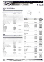
01 – JET PUMP.................................................................................................... 615<br />
GENERAL........................................................................................................... 616<br />
JET PUMP INSPECTION ON WATERCRAFT..................................................................... 616<br />
REMOVAL .......................................................................................................... 618<br />
DISASSEMBLY ..................................................................................................... 620<br />
CLEANING.......................................................................................................... 622<br />
PARTS INSPECTION ............................................................................................... 623<br />
ASSEMBLY ......................................................................................................... 625<br />
PUMP PRESSURIZATION ......................................................................................... 633<br />
INSTALLATION ..................................................................................................... 633<br />
GENERAL........................................................................................................... 637<br />
JET PUMP INSPECTION ON WATERCRAFT..................................................................... 637<br />
REMOVAL .......................................................................................................... 638<br />
DISASSEMBLY ..................................................................................................... 641<br />
CLEANING.......................................................................................................... 644<br />
PARTS INSPECTION ............................................................................................... 644<br />
ASSEMBLY ......................................................................................................... 646<br />
PUMP PRESSURIZATION ......................................................................................... 649<br />
INSTALLATION ..................................................................................................... 650<br />
02 – DRIVE SYSTEM.............................................................................................. 653<br />
GENERAL........................................................................................................... 656<br />
REMOVAL .......................................................................................................... 656<br />
INSPECTION........................................................................................................ 663<br />
ASSEMBLY ......................................................................................................... 665<br />
INSTALLATION ..................................................................................................... 666<br />
LUBRICATION...................................................................................................... 673<br />
03 – REVERSE SYSTEM ......................................................................................... 675<br />
DISASSEMBLY .................................................................................................... 676<br />
IX
TABLE OF CONTENTS<br />
INSPECTION........................................................................................................ 678<br />
ASSEMBLY ......................................................................................................... 678<br />
ADJUSTMENT...................................................................................................... 678<br />
04 – VARIABLE TRIM SYSTEM ................................................................................. 679<br />
GENERAL........................................................................................................... 681<br />
REMOVAL .......................................................................................................... 681<br />
DISASSEMBLY ..................................................................................................... 681<br />
INSPECTION........................................................................................................ 682<br />
ASSEMBLY ......................................................................................................... 682<br />
INSTALLATION ..................................................................................................... 683<br />
ADJUSTMENT...................................................................................................... 683<br />
14 STEERING SYSTEM<br />
01 – STEERING SYSTEM ........................................................................................ 685<br />
DISASSEMBLY ..................................................................................................... 687<br />
ASSEMBLY ......................................................................................................... 692<br />
DISASSEMBLY ..................................................................................................... 697<br />
ASSEMBLY ......................................................................................................... 700<br />
OFF-POWER ASSISTED STEERING SYSTEM (O.P.A.S.).............................................. 702<br />
GENERAL........................................................................................................... 703<br />
SIDE VANE.......................................................................................................... 703<br />
CYLINDER SUPPORT.............................................................................................. 704<br />
TIE ROD............................................................................................................. 705<br />
SEALED TUBE...................................................................................................... 706<br />
FILTER............................................................................................................... 706<br />
VALVE ............................................................................................................... 707<br />
WATER HOSE ...................................................................................................... 707<br />
CROSS SUPPORT PLATE ......................................................................................... 708<br />
02 – ALIGNMENT ................................................................................................. 709<br />
15 SUSPENSION<br />
01 – DIRECT ACTION SUSPENSION........................................................................... 711<br />
REMOVAL .......................................................................................................... 712<br />
INSPECTION........................................................................................................ 713<br />
ASSEMBLY ......................................................................................................... 714<br />
16 HULL/BODY<br />
01 – ADJUSTMENT AND REPAIR.............................................................................. 715<br />
GENERAL........................................................................................................... 733<br />
GLOVE BOX ........................................................................................................ 733<br />
ENGINE COVER.................................................................................................... 735<br />
SEAT ADJUSTMENT............................................................................................... 736<br />
STORAGE COMPARTMENT INNER SHELL ..................................................................... 737<br />
STORAGE COVER SHOCK........................................................................................ 744<br />
STORAGE COMPARTMENT COVER ADJUSTMENT ........................................................... 745<br />
ACCESS PANEL ADJUSTMENT .................................................................................. 746<br />
MIRROR ............................................................................................................ 746<br />
INFO CENTER (LCD GAUGE) ..................................................................................... 747<br />
DEFLECTOR AND/OR UPPER GRID.............................................................................. 747<br />
FINITION PLATE.................................................................................................... 748<br />
INLET GRATE....................................................................................................... 748<br />
RIDING PLATE...................................................................................................... 749<br />
X
TABLE OF CONTENTS<br />
JET PUMP SUPPORT.............................................................................................. 750<br />
DRAIN PLUG INSTALLATION..................................................................................... 751<br />
SEAT REMOVAL.................................................................................................... 752<br />
SEAT COVER REPLACEMENT.................................................................................... 753<br />
BUMPER REPLACEMENT......................................................................................... 753<br />
WAKE PYLON ...................................................................................................... 754<br />
SPONSON REPLACEMENT....................................................................................... 756<br />
ENGINE COMPARTMENT COVER REMOVAL................................................................... 756<br />
DECALS REPLACEMENT.......................................................................................... 757<br />
HULL AND BODY REPAIR......................................................................................... 758<br />
TOOLS AND MATERIALS LIST ................................................................................... 760<br />
THRU-HULL FITTING INSTALLATION ............................................................................ 761<br />
17 <strong>TEC</strong>HNICAL DATA<br />
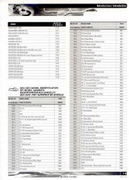
01 – GTI AND GTI LE MODELS ................................................................................. 763<br />
02 – GTI RFI AND GTI LE RFI MODELS........................................................................ 767<br />
03 – XP DI MODEL................................................................................................ 771<br />
04 – RXP 4-<strong>TEC</strong> MODELS........................................................................................ 775<br />
05 – <strong>GTX</strong> 4-<strong>TEC</strong> MODELS ....................................................................................... 781<br />
18 WIRING DIAGRAM<br />
01 – WIRING DIAGRAMS........................................................................................ 787<br />
WIRE COLOR CODES............................................................................................. 787<br />
WIRE DIGIT CODES ............................................................................................... 787<br />
DEUTSCH CONNECTORS......................................................................................... 787<br />
PACKARD CONNECTOR .......................................................................................... 790<br />
AMP PLUG CONNECTOR......................................................................................... 790<br />
IDENTIFICATION OF CONNECTOR PINS........................................................................ 793<br />
ECM CONNECTORS............................................................................................... 794<br />
MAIN FUSE HOLDER JOINT CONNECTOR..................................................................... 797<br />
XI
SAFETY NOTICE<br />
SAFETY NOTICE<br />
This manual has been prepared as a guide to correctly service and repair all 2004 SEA-DOO watercraft.<br />
See model list below.<br />
This edition was primarily published to be used by watercraft mechanical technicians who are already familiar<br />
with all service procedures relating to Bombardier made watercraft. Mechanical technicians should<br />
attend training courses given by Bombardier Training Dept.<br />
Please note that the instructions will apply only if proper hand tools and special service tools are used.<br />
This Shop Manual uses technical terms which may be slightly different from the ones used in the Parts<br />
Catalog.<br />
It is understood that this manual may be translated into another language. In the event of any discrepancy,<br />
the English version shall prevail.<br />
The content depicts parts and/or procedures applicable to the particular product at time of writing. Service<br />
and Warranty Bulletins may be published to update the content of this manual. Make sure to read<br />
and understand these.<br />
In addition, the sole purpose of the illustrations throughout the manual, is to assist identification of the<br />
general configuration of the parts. They are not to be interpreted as technical drawings or exact replicas<br />
of the parts.<br />
The use of Bombardier parts is most strongly recommended when considering replacement of any component.<br />
Dealer and/or distributor assistance should be sought in case of doubt.<br />
The engines and the corresponding components identified in this document should not be utilized on<br />
product(s) other than those mentioned in this document.<br />
WARNING<br />
Torque wrench tightening specifications must be strictly adhered to. Locking devices (ex.: locking<br />
tab, self-locking fasteners, etc.) must be installed or replaced with new ones. If the efficiency<br />
of a locking device is impaired, it must be renewed.<br />
WARNING<br />
Unless otherwise specified, engine should be turned OFF and cold for all maintenance and repair<br />
procedures.<br />
This manual emphasizes particular information denoted by the wording and symbols:<br />
WARNING<br />
Identifies an instruction which, if not followed, could cause serious personal injury including possibility<br />
of death.<br />
CAUTION: Denotes an instruction which, if not followed, could severely damage vehicle components.<br />
NOTE: Indicates supplementary information needed to fully complete an instruction.<br />
Although the mere reading of such information does not eliminate the hazard, your understanding of the<br />
information will promote its correct use. Always use common shop safety practice.<br />
Bombardier Inc. disclaims liability for all damages and/or injuries resulting from the improper use of the<br />
contents. We strongly recommend that any services be carried out and/or verified by a highly skilled<br />
professional mechanic. It is understood that certain modifications may render use of the vehicle illegal<br />
under existing federal, provincial and state regulations.<br />
XII
INTRODUCTION<br />
INTRODUCTION<br />
This Shop Manual covers the following BOM-<br />
BARDIER made SEA-DOO ® 2004 watercraft<br />
models.<br />
MODEL<br />
ENGINE<br />
TYPE<br />
MODEL<br />
NUMBER<br />
HULL IDENTIFICATION NUMBER<br />
(H.I.N.)<br />
It is located on footboard at the rear of watercraft.<br />
GTI (blue jay) 717 6133<br />
GTI International (blue jay) 717 6134<br />
GTI LE (Sonora sand) 717 6135<br />
GTI LE International<br />
(Sonora sand)<br />
717 6136<br />
GTI RFI (blue jay) 787 RFI 6137<br />
GTI RFI International<br />
(blue jay)<br />
787 RFI 6138<br />
GTI RFI LE (Sonora sand) 787 RFI 6139<br />
GTI RFI LE International<br />
(Sonora sand)<br />
787 RFI 6140<br />
<strong>GTX</strong> 4-<strong>TEC</strong> NA 1503 6147<br />
<strong>GTX</strong> 4-<strong>TEC</strong> NA International 1503 6148<br />
<strong>GTX</strong> 4-<strong>TEC</strong> <strong>Supercharged</strong><br />
Limited International<br />
(blue pearl)<br />
<strong>GTX</strong> 4-<strong>TEC</strong> <strong>Supercharged</strong><br />
Limited (blue pearl)<br />
<strong>GTX</strong> 4-<strong>TEC</strong> <strong>Supercharged</strong><br />
(yellow)<br />
<strong>GTX</strong> 4-<strong>TEC</strong> <strong>Supercharged</strong><br />
International (yellow)<br />
<strong>GTX</strong> 4-<strong>TEC</strong> Wakeboard<br />
Edition (viper red)<br />
<strong>GTX</strong> 4-<strong>TEC</strong> Wakeboard<br />
Edition International<br />
(viper red)<br />
1503 6142<br />
1503 6141<br />
1503 6143<br />
1503 6144<br />
1503 6149<br />
1503 6150<br />
F00L2EA 1<br />
1. Hull Identification Number (H.I.N.)<br />
RXP (apple green) 1503 6115<br />
RXP International<br />
(apple green)<br />
1503 5599<br />
F08L0QA 1<br />
RXP (yellow) 1503 6162<br />
RXP International (yellow) 1503 6163<br />
XP DI (viper red) 947 DI 6151<br />
XP DI International (viper red) 947 DI 6152<br />
TYPICAL<br />
1. Hull Identification Number (H.I.N.)<br />
All Models<br />
The Hull Identification Number is composed of 12<br />
digits:<br />
XIII
INTRODUCTION<br />
Z Z N 1 2 3 4 5 L 4 9 5<br />
F00A0CB<br />
Serial<br />
number*<br />
Manufacturer<br />
*A letter may also be used as a digit.<br />
Model year<br />
Year of production<br />
Month of production<br />
ENGINE IDENTIFICATION<br />
NUMBER (E.I.N.)<br />
717 Engines<br />
The Engine Identification Number is located on the<br />
upper side of the mag<strong>net</strong>o housing.<br />
F01D87A 1<br />
1. Engine Identification Number (E.I.N.)<br />
1<br />
947 DI Engines<br />
The Engine Identification Number is located on the<br />
upper crankcase on MAGNETO side.<br />
F01D01A<br />
TYPICAL<br />
1. Engine Identification Number (E.I.N.)<br />
787 RFI Engines<br />
The Engine Identification Number is located on the<br />
upper crankcase on PTO side.<br />
F06D15A 1<br />
1. Engine Identification Number (E.I.N.)<br />
1503 Engines<br />
The Engine Identification Number is located on<br />
front end of the engine.<br />
XIV
INTRODUCTION<br />
1<br />
F18D03A<br />
1. Engine Identification Number (E.I.N.)<br />
ARRANGEMENT OF THIS<br />
MANUAL<br />
The manual is divided into many major sections as<br />
you can see in the main table of contents at the<br />
beginning of the manual.<br />
Several sections are divided in various subsections.<br />
There is a table of contents at the beginning<br />
of many sections.<br />
XV
INTRODUCTION<br />
TYPICAL PAGE<br />
Page heading<br />
indicates section<br />
and subsection<br />
detailed.<br />
Subsection title<br />
indicates<br />
beginning of the<br />
subsection.<br />
Subsection 04<br />
(MAGNETO SYSTEM)<br />
Italic sub-title<br />
above exploded<br />
view indicate<br />
pertaining models.<br />
Drop represents<br />
a liquid product<br />
to be applied to a<br />
surface. In this case<br />
Loctite 243 to<br />
screw threads.<br />
Loctite<br />
243<br />
Exploded view<br />
assists you in<br />
identifying parts and<br />
related positions.<br />
Loctite<br />
243<br />
Loctite<br />
243<br />
Loctite<br />
243<br />
Dotted box<br />
contains parts of<br />
a particular<br />
model or an<br />
exploded view.<br />
Loctite<br />
243<br />
Bold face number<br />
indicates special<br />
procedure<br />
concerning this part.<br />
Loctite<br />
648<br />
145 N•m<br />
(107 lbf•ft)<br />
Anti-seize<br />
lubricant<br />
Illustration number<br />
for publishing<br />
process.<br />
F01D4WS<br />
30<br />
Page number<br />
F01A0CT<br />
XVI
INTRODUCTION<br />
TYPICAL PAGE<br />
Sub-title with part<br />
name(s) from<br />
exploded view.<br />
Section 06 FUEL SYSTEM<br />
Subsection 03 (CARBURETORS)<br />
Title indicates main<br />
procedure to be<br />
carried-out.<br />
Service tool to be<br />
used to perform a<br />
certain procedure.<br />
Title in italic indicates a<br />
particular procedure<br />
concerning a model.<br />
CARBURETOR REMOVAL<br />
To remove carburetors from engine, proceed as follows:<br />
Remove air vent tube support.<br />
Unlock retaining slides holding air intake silencer base.<br />
Remove air intake silencer base from watercraft.<br />
Remove screws holding flame arrester base support<br />
to cylinder head cover.<br />
Unscrew base retaining screws then remove base from<br />
carburetors and move to front of watercraft.<br />
Turn the valve to OFF position.<br />
NOTE: For fuel line removal, use pliers (P/N 295<br />
000 054).<br />
Disconnect pulse line from fuel pump.<br />
Disconnect fuel fuel supply line from fuel pump.<br />
Disconnect fuel return line.<br />
Disconnect oil injection pump cable, throttle cable and<br />
choke cable.<br />
XP Model Only<br />
Remove screws no. 6 and lock washers no. 7 retaining<br />
carburetors.<br />
DISASSEMBLY AND INSPECTION<br />
Inspect parts for corrosion dammage (shaft, butterfly,<br />
spring screw, check valve housing, etc.).<br />
Diaphragm<br />
PUMP DIAPHRAGM LEAK TEST<br />
Using a suitable pump gauge tester, perform the following<br />
test proceeding as follows:<br />
- Install pump gauge tester (P/N 295 000 083) on pulse<br />
nipple.<br />
- Pump tester until it reaches 28 kPa (4 PSI).<br />
1<br />
A<br />
Sub-sub-title in<br />
capital indicates a<br />
particular testing,<br />
adjustment or<br />
repair procedure.<br />
Illustration<br />
always follows<br />
text it is<br />
pertained to.<br />
Sub-sub-title in this<br />
case indicates that<br />
particular procedure<br />
for XP is finished, so<br />
from this point, all<br />
others models are<br />
concerned.<br />
All Others Models<br />
Remove 4 bolts no. 8 and lock washers no. 12 from<br />
rotary valve cover then move carburetors and rotary<br />
valve cover on top of engine.<br />
NOTE: When removing rotary valve cover , pay<br />
attention that the rotary valve stay in place, other-wise<br />
it must be timed.<br />
Remove carburetors from intake manifold.<br />
Disconnect fuel bypass line between carburetors (twin<br />
carburetors).<br />
Remove carburetor(s) from rotary valve cover.<br />
F01F0XB<br />
TYPICAL<br />
1<br />
2<br />
2<br />
1 2<br />
Diaphragm must stand pressure for 10 seconds. If<br />
pressure drops, replace diaphragm.<br />
“TYPICAL” mention<br />
indicates a general<br />
view which does not<br />
represent full detail.<br />
Numbered step are<br />
used to give a<br />
sequence to be<br />
perfomed.<br />
Letters are used for<br />
any measures.<br />
31<br />
Bold numbers in the<br />
text refer to the parts<br />
shown in the exploded<br />
view at the beginning<br />
of the subsection.<br />
Numbers are used<br />
for description of<br />
components.<br />
F01A0BT<br />
XVII
INTRODUCTION<br />
LIST OF ABBREVIATIONS USED<br />
IN THIS MANUAL<br />
ABBREVI-<br />
ATION<br />
4-<strong>TEC</strong> NA<br />
ADC<br />
AC<br />
APS<br />
ATS<br />
B.U.D.S.<br />
DESCRIPTION<br />
Naturally-Aspirated Engine<br />
Analog to Digital Conversion<br />
Alternate Current<br />
Air Pressure Sensor<br />
Air Temperature Sensor<br />
Bombardier Utility and Diagnostic Software<br />
ABBREVI-<br />
ATION<br />
TBD<br />
TDC<br />
TPS<br />
VDC<br />
VCK<br />
Vdc<br />
VTS<br />
WTS<br />
DESCRIPTION<br />
To Be Determined<br />
Top Dead Center<br />
Throttle Position Sensor<br />
Volt Direct Current<br />
Vehicle Communication Kit<br />
Volt Direct Current<br />
Variable Trim System<br />
Water Temperature Sensor<br />
CDI<br />
CPS<br />
CSI<br />
DC<br />
DESS<br />
DI<br />
E.I.N.<br />
ECM<br />
ECU<br />
EPA<br />
HP<br />
LED<br />
IC<br />
LED<br />
MAG<br />
MPEM<br />
MPH<br />
MPI<br />
N.A.<br />
OPT<br />
P/N<br />
PFD<br />
PSI<br />
PTO<br />
RAVE<br />
RFI<br />
RPM<br />
Sc<br />
STD<br />
Capacitor Discharge Ignition<br />
Crankshaft Position Sensor<br />
Cooling System Indicator<br />
Direct Current<br />
Digitally Encoded Security System<br />
Direct Injection<br />
Engine Identification Number<br />
Engine Control Module<br />
Electronic Control Unit<br />
Environmental Protection Agency (USA)<br />
Horse Power<br />
Light Emitting Diode<br />
Intercooler<br />
Light Emitting Diode<br />
Mag<strong>net</strong>o<br />
Multi-Purpose Electronic Module<br />
Mile Per Hour<br />
Multi Protocol Interface<br />
Not Applicable<br />
Optional<br />
Part Number<br />
Personal Flotation Device<br />
Pound Per Square Inch<br />
Power Take Off<br />
Rotax Adjustable Variable Exhaust<br />
Rotax Fuel Injection<br />
Revolution Per Minute<br />
Supercharger<br />
Standard<br />
GENERAL INFORMATION<br />
The use of RIGHT (starboard) and LEFT (port) indications<br />
in the text, always refers to driving position<br />
(when sitting on watercraft).<br />
Besides, in the marine industry, FRONT is called<br />
BOW and REAR is called STERN.<br />
F01L45B<br />
1. Left (port)<br />
2. Right (starboard)<br />
1 2<br />
The information and component/system descriptions<br />
contained in this manual are correct at time<br />
of writing. Bombardier Inc. however, maintains a<br />
policy of continuous improvement of its products<br />
without imposing upon itself any obligation to install<br />
them on products previously manufactured.<br />
Bombardier Inc. reserves the right at any time to<br />
discontinue or change specifications, designs, features,<br />
models or equipment without incurring obligation.<br />
This Shop Manual uses technical terms which may<br />
be different from the ones of the Parts Catalogs.<br />
When ordering parts always refer to the specific<br />
model Parts Catalogs.<br />
XVIII
INTRODUCTION<br />
ILLUSTRATIONS AND<br />
PROCEDURES<br />
The illustrations show the typical construction of<br />
the different assemblies and, in all cases, may not<br />
reproduce the full detail or exact shape of the parts<br />
shown, however, they represent parts which have<br />
the same or a similar function.<br />
CAUTION: These watercraft are designed with<br />
parts dimensioned mostly in the metric system.<br />
However some components may be from<br />
the imperial system. When replacing fasteners,<br />
make sure to use only those recommended<br />
by Bombardier.<br />
As many of the procedures in this manual are interrelated,<br />
we suggest, that before undertaking any<br />
task, you read and thoroughly understand the entire<br />
section or subsection in which the procedure<br />
is contained.<br />
A number of procedures throughout the book require<br />
the use of special tools. Before undertaking<br />
any procedure, be sure that you have on hand all<br />
the tools required, or approved equivalents.<br />
ENGINE EMISSIONS<br />
INFORMATION<br />
Manufacturer's Responsibility<br />
Beginning with 1999 model year engines, PWC<br />
manufacturers of marine engines must determine<br />
the exhaust emission levels for each engine horsepower<br />
family and certify these engines with the<br />
United States of America Environmental Protection<br />
Agency (EPA). An emissions control information<br />
label, showing emission levels and engine<br />
specifications, must be placed on each vehicle at<br />
the time of manufacture.<br />
Dealer Responsibility<br />
When performing service on all 1999 and more<br />
recent <strong>Sea</strong>-<strong>Doo</strong> watercrafts that carry an emissions<br />
control information label, adjustments must<br />
be kept within published factory specifications.<br />
Replacement or repair of any emission related<br />
component must be executed in a manner that<br />
maintains emission levels within the prescribed<br />
certification standards.<br />
Dealers are not to modify the engine in any manner<br />
that would alter the horsepower or allow emission<br />
levels to exceed their predetermined factory<br />
specifications.<br />
Exceptions include manufacturer's prescribed<br />
changes, such as altitude adjustments for example.<br />
Owner Responsibility<br />
The owner/operator is required to have engine<br />
maintenance performed to maintain emission<br />
levels within prescribed certification standards.<br />
The owner/operator is not to, and should not allow<br />
anyone to modify the engine in any manner<br />
that would alter the horsepower or allow emissions<br />
levels to exceed their predetermined factory<br />
specifications.<br />
EPA Emission Regulations<br />
All new 1999 and more recent <strong>Sea</strong>-<strong>Doo</strong> watercrafts<br />
manufactured by Bombardier are certified<br />
to the EPA as conforming to the requirements of<br />
the regulations for the control of air pollution from<br />
new watercraft engines. This certification is contingent<br />
on certain adjustments being set to factory<br />
standards. For this reason, the factory procedure<br />
for servicing the product must be strictly followed<br />
and, whenever practicable, returned to the original<br />
intent of the design.<br />
The responsibilities listed above are general and<br />
in no way a complete listing of the rules and regulations<br />
pertaining to the EPA requirements on exhaust<br />
emissions for marine products. For more<br />
detailed information on this subject, you may contact<br />
the following locations:<br />
VIA U.S. POSTAL SERVICE:<br />
Office of Mobile Sources<br />
Engine Programs and Compliance Division<br />
Engine Compliance Programs Group (6403J)<br />
401 M St. NW Washington, DC 20460<br />
VIA EXPRESS or COURIER MAIL:<br />
Office of Mobile Sources<br />
Engine Programs and Compliance Division<br />
Engine Compliance Programs Group (6403J)<br />
501 3 rd St. NW Washington, DC 20001<br />
XIX
INTRODUCTION<br />
EPA INTERNET WEB SITE:<br />
http:/www.epa.gov/omswww<br />
SELF-LOCKING FASTENERS<br />
PROCEDURE<br />
The following describes the most common application<br />
procedures when working with self-locking<br />
fasteners.<br />
Use a metal brush or a screwtap to clean the hole<br />
properly then use a solvent (Methyl-Chloride), let<br />
act during 30 minutes and wipe off. The solventutilization<br />
is to ensure the adhesive works properly.<br />
– Apply a few drops of threadlocker at proposed<br />
tightened nut engagement area.<br />
– Position nut and tighten as required.<br />
Blind Holes<br />
2<br />
1<br />
LOCTITE APPLICATION<br />
PROCEDURE<br />
The following describes the most common application<br />
procedures when working with Loctite<br />
products.<br />
NOTE: Always use proper strength Loctite product<br />
as recommended in this Shop Manual.<br />
THREADLOCKER<br />
Uncovered Holes (bolts and nuts)<br />
1<br />
A00A3MA<br />
1. On threads<br />
2. On threads and at the bottom of hole<br />
– Clean threads (bolt and hole) with solvent.<br />
– Apply Loctite Primer N (P/N 293 800 041) on<br />
threads (bolt and nut) and allow to dry for 30<br />
seconds.<br />
– Choose proper strength Loctite threadlocker.<br />
– Apply several drops along the threaded hole and<br />
at the bottom of the hole.<br />
– Apply several drops on bolt threads.<br />
– Tighten as required.<br />
Stud in Blind Holes<br />
1 3<br />
2<br />
2<br />
A00A3LA<br />
1. Apply here<br />
2. Do not apply<br />
– Clean threads (bolt and nut) with solvent.<br />
– Apply Loctite Primer N (P/N 293 800 041) on<br />
threads and allow to dry.<br />
– Choose proper strength Loctite threadlocker.<br />
– Fit bolt in the hole.<br />
A00A5RA<br />
1. On threads<br />
2. On threads and in the hole<br />
3. Onto nut threads<br />
– Clean threads (stud and hole) with solvent.<br />
XX
INTRODUCTION<br />
– Apply Loctite Primer N (P/N 293 800 041) on<br />
threads and allow to dry.<br />
– Put several drops of proper strength Loctite<br />
threadlocker on female threads and in hole.<br />
– Apply several drops of proper strength Loctite<br />
on stud threads.<br />
– Install stud.<br />
– Install cover, etc.<br />
– Apply drops of proper strength Loctite on uncovered<br />
threads.<br />
– Tighten nuts as required.<br />
Adjusting Screw<br />
1<br />
2<br />
Preassembled Parts<br />
A00A3PA<br />
1. Apply here<br />
2. Plunger<br />
1<br />
– Adjust screw to proper setting.<br />
– Apply drops of proper strength Loctite threadlocker<br />
on screw/body contact surfaces.<br />
– Avoid touching metal with tip of flask.<br />
NOTE: if it is difficult to readjust, heat screw with<br />
a soldering iron (232°C (450°F)).<br />
2<br />
A00A3OA<br />
1. Apply here<br />
2. Do not apply<br />
STRIPPED THREAD REPAIR<br />
Stripped Threads<br />
5<br />
– Clean bolts and nuts with solvent.<br />
– Assemble components.<br />
– Tighten nuts.<br />
– Apply drops of proper strength Loctite on<br />
bolt/nut contact surfaces.<br />
– Avoid touching metal with tip of flask.<br />
NOTE: for preventive maintenance on existing<br />
equipment, retighten nuts and apply proper<br />
strength Loctite on bolt/nut contact surfaces.<br />
A00A3QA<br />
2<br />
1<br />
3<br />
4<br />
8<br />
7<br />
6<br />
1. Release agent<br />
2. Stripped threads<br />
3. Form-A-Thread<br />
4. Tape<br />
5. Cleaned bolt<br />
6. Plate<br />
7. New threads<br />
8. Threadlocker<br />
Standard Thread Repair<br />
– Follow instructions on Loctite FORM-A-<br />
THREAD 81668 package.<br />
XXI
INTRODUCTION<br />
– if a plate is used to align bolt:<br />
a. Apply release agent on mating surfaces.<br />
b. Put waxed paper or similar film on the surfaces.<br />
– Twist bolt when inserting it to improve thread<br />
conformation.<br />
NOTE: NOT intended for engine stud repairs.<br />
Repair of Small Holes/Fine Threads<br />
Option 1: Enlarge damaged hole, then follow<br />
Standard Thread Repair procedure.<br />
Option 2: Apply FORM-A-THREAD on the screw<br />
and insert in damaged hole.<br />
Permanent Stud Installation (light duty)<br />
– Use a stud or thread on desired length.<br />
– DO NOT apply release agent on stud.<br />
– Do a Standard Thread Repair.<br />
– Allowtocurefor30minutes.<br />
– Assemble.<br />
GASKET COMPOUND<br />
All Parts<br />
1<br />
2<br />
– Spray Loctite Primer N on both mating surfaces<br />
and on both sides of gasket. Allow to dry 1 or<br />
2minutes.<br />
– Apply GASKET ELIMINATOR 518 (P/N 293 800<br />
038) on both sides of gasket, using a clean applicator.<br />
– Place gasket on mating surfaces and assemble<br />
immediately.<br />
NOTE: If the cover is bolted to blind holes (above),<br />
apply proper strength Loctite in the hole and on<br />
threads. Tighten.<br />
If holes are sunken, apply proper strength Loctite<br />
on bolt threads.<br />
– Tighten as usual.<br />
MOUNTINGONSHAFT<br />
Mounting with a Press<br />
1<br />
2<br />
3<br />
1<br />
A00A3UA<br />
1. Bearing<br />
2. Proper strength Loctite<br />
3. Shaft<br />
A00A3SA<br />
1 3<br />
1. Proper strength Loctite<br />
2. Loctite Primer N (P/N 293 800 041) and Gasket Eliminator<br />
518 (P/N 293 800 038) on both sides of gasket<br />
3. Loctite Primer N only<br />
– Remove old gasket and other contaminants<br />
with Loctite Chisel remover (P/N 413 708 500).<br />
Use a mechanical mean if necessary.<br />
NOTE: Avoid grinding.<br />
– Clean both mating surfaces with solvent.<br />
Standard<br />
– Clean shaft external part and element internal<br />
part.<br />
– Apply a strip of proper strength Loctite on shaft<br />
circumference at insert or engagement point.<br />
NOTE: Retaining compound is always forced out<br />
whenappliedonshaft.<br />
– DO NOT use anti-seize Loctite or any similar<br />
product.<br />
– No curing period is required.<br />
XXII
INTRODUCTION<br />
Mounting in Tandem<br />
1) Apply retaining compound on internal element<br />
bore.<br />
2) Continue to assemble as shown above.<br />
CASE-IN COMPONENTS<br />
Metallic Gaskets<br />
A00A3VA 1<br />
1. Proper strength Loctite<br />
– Clean inner housing diameter and outer gasket<br />
diameter.<br />
– Spray housing and gasket with Loctite Primer N<br />
(P/N 293 800 041).<br />
– Apply a strip of proper strength Loctite on leading<br />
edge of outer metallic gasket diameter.<br />
NOTE: Any Loctite product can be used here. A<br />
low strength liquid is recommended as normal<br />
strength and gap are required.<br />
– Install according to standard procedure.<br />
– Wipe off surplus.<br />
– Allowittocurefor30minutes.<br />
NOTE: Normally used on worn-out housings to<br />
prevent leaking or sliding.<br />
It is generally not necessary to remove gasket<br />
compound applied on outer gasket diameter.<br />
XXIII
INTRODUCTION<br />
TIGHTENING TORQUES<br />
Tighten fasteners to torque mentioned in exploded views and/or text, When they are not specified, refer<br />
to following table.<br />
WARNING<br />
Torque wrench tightening specifications must strictly be adhered to. Locking devices (ex.: locking<br />
tabs, elastic stop nuts, self-locking fasteners, etc.) must be installed or replaced with new<br />
ones, where specified. If the efficiency of a locking device is impaired, it must be renewed.<br />
In order to avoid a poor assembling, tighten screws, bolts or nuts in accordance with the following procedure:<br />
– Manually screw all screws, bolts and/or nuts.<br />
– Apply the half of the recommended torque value.<br />
CAUTION: Be sure to use the proper tightening torque for the proper strength grade.<br />
NOTE: When possible, always apply torque on the nut.<br />
– Torque to the recommended torque value.<br />
NOTE: Always torque screws, bolts and/or nuts in a criss-cross sequence.<br />
4.8<br />
8.8<br />
9.8<br />
10.9<br />
12.9<br />
Property<br />
class<br />
and<br />
head<br />
markings<br />
4.8<br />
4.8<br />
8.8<br />
8.8<br />
9.8<br />
9.8<br />
10.9<br />
10.9<br />
12.9<br />
12.9<br />
12.9<br />
Property<br />
class<br />
and<br />
nut<br />
markings<br />
5<br />
5<br />
10<br />
10<br />
10<br />
10<br />
12<br />
12<br />
A00A8BS<br />
FASTENER<br />
SIZE<br />
FASTENER GRADE/TORQUE<br />
5.8 Grade 8.8 Grade 10.9 Grade 12.9 Grade<br />
M4<br />
1.5 — 2N•m<br />
(13 — 18 lbf•in)<br />
2.5 — 3N•m<br />
(22 — 27 lbf•in)<br />
3.5 — 4N•m<br />
(31 — 35 lbf•in)<br />
4 — 5 N•m<br />
(35 — 44 lbf•in)<br />
M5<br />
3 — 3.5 N•m<br />
(27 — 31 lbf•in)<br />
4.5 — 5.5 N•m<br />
(40 — 47 lbf•in)<br />
7 — 8.5 N•m<br />
(62 — 75 lbf•in)<br />
8 — 10 N•m<br />
(71 — 89 lbf•in)<br />
M6<br />
6.5 — 8.5 N•m<br />
(58 — 75 lbf•in)<br />
8 — 12 N•m<br />
(71 — 106 lbf•in)<br />
10.5 — 15 N•m<br />
(93 — 133 lbf•in)<br />
16 N•m (142 lbf•in)<br />
M8 15 N•m (11lbf•ft) 24.5 N•m (18lbf•ft) 31.5 N•m (23lbf•ft) 40 N•m (30lbf•ft)<br />
M10 29 N•m (21lbf•ft) 48 N•m (35lbf•ft) 61 N•m (45lbf•ft) 72.5 N•m (53lbf•ft)<br />
M12 52 N•m (38lbf•ft) 85 N•m (63lbf•ft) 105 N•m (77lbf•ft) 127.5 N•m (94lbf•ft)<br />
M14 85 N•m (63lbf•ft) 135 N•m (100lbf•ft) 170 N•m (125 lbf•ft) 200 N•m (148 lbf•ft)<br />
XXIV
110<br />
1 8 0<br />
280<br />
70<br />
9 0<br />
Section 01 SERVICE TOOLS AND PRODUCTS<br />
Subsection 01 (MANDATORY SERVICE TOOLS )<br />
MANDATORY SERVICE TOOLS<br />
NOTE: N–> indicates a new tool.<br />
ENGINE<br />
Degree wheel<br />
(P/N 529 035 605)<br />
3 1 0<br />
60<br />
3 20<br />
50<br />
33 0<br />
40<br />
3 4 0<br />
30<br />
20<br />
3 50<br />
10<br />
36 0<br />
360<br />
10<br />
350<br />
2 0<br />
340<br />
3 0<br />
330<br />
4 0<br />
320<br />
310<br />
5 0<br />
6 0<br />
Sleeve set<br />
a. (P/N 529 035 542)<br />
(20 mm sleeve)<br />
b. (P/N 529 035 543)<br />
(21 mm sleeve)<br />
Carbon dam compressor<br />
(P/N 529 035 716)<br />
3 0 0<br />
70<br />
300 290<br />
2 90<br />
80<br />
90<br />
8 0<br />
2 80<br />
100<br />
2 70<br />
2 60<br />
2 50<br />
130 120<br />
2 4 0<br />
140<br />
2 3 0<br />
150<br />
22 0<br />
160<br />
210<br />
170<br />
2 0 0<br />
APPLICATION<br />
717 and 787 RFI engines.<br />
180<br />
1 9 0<br />
Piston circlip installer<br />
190<br />
a) (P/N 529 035 562)<br />
200<br />
1 7 0<br />
210<br />
160<br />
220<br />
1 5 0<br />
230<br />
240<br />
1 3 0 1 40<br />
250<br />
260<br />
270<br />
1 20<br />
1 1 0<br />
100<br />
APPLICATION<br />
a. 717 and 787 RFI engines.<br />
b. 947 DI engines.<br />
Air compressor ring compressor<br />
(P/N 529 035 713)<br />
APPLICATION<br />
947 DI engines.<br />
Bearing pusher<br />
(P/N 420 876 501)<br />
APPLICATION<br />
717 and 787 RFI engines.<br />
b) (P/N 529 035 765)<br />
APPLICATION<br />
a. 2-stroke engines.<br />
b. 4-<strong>TEC</strong> engines<br />
APPLICATION<br />
947 DI engines.<br />
Carbon dam guide<br />
(P/N 529 035 715)<br />
APPLICATION<br />
947 DI engines.<br />
PTO flywheel remover/installer<br />
a. (P/N 295 000 001)<br />
b. (P/N 529 035 820)<br />
APPLICATION<br />
a. 717 engines.<br />
b. 4-<strong>TEC</strong> engines.<br />
NOTE: This tool is also used for<br />
the impeller.<br />
Starter drive bearing pusher<br />
(P/N 420 876 502)<br />
APPLICATION<br />
947 DI engines.<br />
smr2004-Complete Line Up 1
Section 01 SERVICE TOOLS AND PRODUCTS<br />
Subsection 01 (MANDATORY SERVICE TOOLS )<br />
Piston pin puller<br />
(P/N 529 035 503)<br />
Expansion sleeve<br />
(P/N 295 000 117)<br />
(787 RFI engines)<br />
APPLICATION<br />
All 2-stroke engines.<br />
Puller<br />
(P/N 529 035 547)<br />
Puller plate<br />
(P/N 520 035 533)<br />
Extension handle<br />
(P/N 295 000 125)<br />
Screw M8 x 35 (3)<br />
(P/N 420 841 591)<br />
Pusher<br />
(P/N 420 876 605)<br />
APPLICATION<br />
717 engines.<br />
Puller ass'y<br />
(P/N 290 876 488)<br />
1) Screw<br />
(P/N 290 240 860)<br />
2) Hexagonal nut<br />
(P/N 290 242 210)<br />
2 1<br />
APPLICATION<br />
717 and 787 RFI engines.<br />
Alignment support plate kit<br />
(P/N 529 035 506)<br />
1) Alignment plates<br />
(P/N 529 035 507)<br />
2) Support<br />
(P/N 529 035 511)<br />
3) Screw (2)<br />
(P/N 207 182 544)<br />
4) Lock washer (2)<br />
(P/N 234 181 601)<br />
5) Flat washer (2)<br />
(P/N 234 081 410)<br />
Alignment shaft<br />
(P/N 295 000 141)<br />
APPLICATION<br />
All models.<br />
Adapter<br />
(P/N 529 035 590)<br />
APPLICATION<br />
XP DI models.<br />
Alignment adaptor<br />
(P/N 529 035 719)<br />
APPLICATION<br />
<strong>GTX</strong> 4-<strong>TEC</strong> models.<br />
N–> VCK<br />
(Vehicle Communication Kit)<br />
(P/N 529 035 981)<br />
Sleeve (3)<br />
(P/N 290 847 220)<br />
APPLICATION<br />
717 engines. Puller is also used<br />
for PTO flywheel on 947 DI engines.<br />
APPLICATION<br />
All models.<br />
APPLICATION<br />
All models.<br />
2 smr2004-Complete Line Up
Section 01 SERVICE TOOLS AND PRODUCTS<br />
Subsection 01 (MANDATORY SERVICE TOOLS )<br />
Flywheel extractor<br />
(P/N 295 000 156)<br />
Handle<br />
(P/N 420 877 650)<br />
Ring gear puller tool<br />
(P/N 420 976 235) (puller ass'y)<br />
(P/N 529 035 549) (puller bolt)<br />
APPLICATION<br />
Usewithpushers(P/N290876<br />
609) and (P/N 290 877 740).<br />
APPLICATION<br />
787 RFI engines.<br />
Engine leak tester kit<br />
(P/N 295 500 352)<br />
Rotary valve shaft pusher<br />
(P/N 290 876 609)<br />
APPLICATION<br />
787 RFI and 947 DI engines.<br />
Crankshaft protective cap<br />
a. (P/N 420 876 557)<br />
b. (P/N 290 877 414)<br />
APPLICATION<br />
717, 787 RFI , 947 DI engines.<br />
Supplementary engine leak test<br />
kit<br />
(P/N 295 500 780)<br />
1a) 787 RFI Intake plate<br />
(P/N 296 000 024)<br />
1b) 947 DI Intake plate<br />
(P/N 296 000 025)<br />
2) 947 DI Rave plate<br />
(P/N 296 000 026)<br />
3) 947 DI Exhaust plate<br />
(P/N 296 000 027)<br />
1 2<br />
3<br />
APPLICATION<br />
787 RFI engines.<br />
Usewithhandle(P/N420877<br />
650).<br />
Oil seal pusher<br />
(P/N 290 877 740)<br />
APPLICATION<br />
787 RFI engines.<br />
Usewithhandle(P/N420877<br />
650).<br />
A<br />
APPLICATION<br />
a. 717 and 787 RFI engines.<br />
b. 947 DI engines.<br />
Polygonal wrench<br />
(P/N 529 035 505)<br />
APPLICATION<br />
Exhaust system of the 947 DI<br />
engines.<br />
B<br />
APPLICATION<br />
787 RFI and 947 DI engines.<br />
NOTE: This kit is supplementary<br />
to (P/N 295 500 352).<br />
smr2004-Complete Line Up 3
Section 01 SERVICE TOOLS AND PRODUCTS<br />
Subsection 01 (MANDATORY SERVICE TOOLS )<br />
Ring gear blocking tool kit<br />
a) (P/N 529 035 846)<br />
Camshaft looking tool<br />
(P/N 529 035 839)<br />
Retaining key<br />
(P/N 529 035 949)<br />
APPLICATION<br />
4-<strong>TEC</strong> engines.<br />
b) (P/N 529 035 946)<br />
N–> Drive shaft adaptor<br />
a. (P/N 529 035 892)<br />
b. (P/N 529 035 985)<br />
APPLICATION<br />
4-<strong>TEC</strong> <strong>Supercharged</strong> engines.<br />
4-pin socket<br />
(P/N 529 035 948)<br />
APPLICATION<br />
a. 787 RFI engines.<br />
b. 947 DI engines.<br />
Intake plug<br />
(P/N 529 035 708)<br />
APPLICATION<br />
947 DI engines.<br />
APPLICATION<br />
a. <strong>GTX</strong> 4-<strong>TEC</strong> engines.<br />
b. RXP 4-<strong>TEC</strong> engines.<br />
Torx adapter<br />
(P/N 529 035 938)<br />
APPLICATION<br />
4-<strong>TEC</strong> <strong>Supercharged</strong> engines.<br />
Support plate<br />
(P/N 529 035 947)<br />
APPLICATION<br />
4-<strong>TEC</strong> <strong>Supercharged</strong> engines.<br />
Ball bearing support/pusher<br />
(P/N 529 035 950)<br />
Crankshaft looking tool<br />
(P/N 529 035 821)<br />
APPLICATION<br />
4-<strong>TEC</strong> engines.<br />
APPLICATION<br />
4-<strong>TEC</strong> <strong>Supercharged</strong> engines.<br />
APPLICATION<br />
4-<strong>TEC</strong> <strong>Supercharged</strong> engines.<br />
4 smr2004-Complete Line Up
Section 01 SERVICE TOOLS AND PRODUCTS<br />
Subsection 01 (MANDATORY SERVICE TOOLS )<br />
COOLING/FUEL/OIL SYSTEMS<br />
Gear holder<br />
(P/N 420 277 905)<br />
Fuel pressure gauge<br />
(P/N 529 035 591)<br />
Oil pressure gauge (1 to 8 bars)<br />
(P/N 529 035 709)<br />
APPLICATION<br />
717 engines.<br />
Pliers<br />
(P/N 295 000 070)<br />
APPLICATION<br />
787 RFI and 4-<strong>TEC</strong> engines.<br />
APPLICATION<br />
4-<strong>TEC</strong> engines.<br />
APPLICATION<br />
All models.<br />
Pliers<br />
(P/N 295 000 054)<br />
1) Fuel pressure gauge<br />
(P/N 529 035 709)<br />
2) Fuel pressure gauge T-fitting<br />
(P/N 529 035 710)<br />
3) Fuel pressure gauge<br />
pressure relief valve<br />
(P/N 529 035 711)<br />
4) Fuel pressure gauge air<br />
compressor adapter<br />
(P/N 529 035 712)<br />
Engine oil pressure adapter<br />
(P/N 529 035 652)<br />
APPLICATION<br />
All models.<br />
NOTE: This tool is also used for<br />
the propulsion system.<br />
1<br />
APPLICATION<br />
4-<strong>TEC</strong> engines.<br />
Oilsealguide<br />
(P/N 529 035 822)<br />
Fuel line disconnect tool<br />
(P/N 529 035 714)<br />
3 2 4<br />
APPLICATION<br />
947 DI engines.<br />
APPLICATION<br />
4-<strong>TEC</strong> engines.<br />
APPLICATION<br />
947 DI engines.<br />
smr2004-Complete Line Up 5
Section 01 SERVICE TOOLS AND PRODUCTS<br />
Subsection 01 (MANDATORY SERVICE TOOLS )<br />
Coolant pump seal pusher<br />
(P/N 529 035 823)<br />
APPLICATION<br />
4-<strong>TEC</strong> engines.<br />
PROPULSION SYSTEM<br />
N–> Impeller remover/installer<br />
a. (P/N 295 000 001)<br />
b. (P/N 529 035 820)<br />
c. (P/N 529 035 956)<br />
Impeller shaft holder<br />
(P/N 295 000 082)<br />
Inner seal installer<br />
(P/N 529 035 609)<br />
APPLICATION<br />
a. All 2-stroke models.<br />
b. <strong>GTX</strong> 4-<strong>TEC</strong> engines.<br />
c. RXP 4-<strong>TEC</strong> engines.<br />
NOTE: This tool is also used<br />
for the PTO flywheel (on some<br />
models).<br />
Pliers<br />
(P/N 295 000 069)<br />
APPLICATION<br />
All 2-stroke models.<br />
Jet pump bearing remover<br />
(P/N 295 000 144)<br />
APPLICATION<br />
All 2-stroke models.<br />
Bearing/seal installer<br />
(P/N 295 000 107)<br />
APPLICATION<br />
155.6 mm (6-1/8 in) jet pump.<br />
Impeller shaft guide<br />
(P/N 295 000 002)<br />
APPLICATION<br />
All models.<br />
APPLICATION<br />
All 2-stroke models.<br />
APPLICATION<br />
All 2-stroke models.<br />
6 smr2004-Complete Line Up
Section 01 SERVICE TOOLS AND PRODUCTS<br />
Subsection 01 (MANDATORY SERVICE TOOLS )<br />
Pliers<br />
(P/N 295 000 054)<br />
N–> Drive shaft holder<br />
a. (P/N 529 035 871)<br />
b. (P/N 529 035 987)<br />
Shaft pusher<br />
(P/N 529 035 819)<br />
APPLICATION<br />
All models.<br />
NOTE: This tool is also used for<br />
the fuel system.<br />
VTS tool<br />
(P/N 295 000 133)<br />
APPLICATION<br />
XP DI models.<br />
Drive shaft alignment tool<br />
(P/N 529 035 590)<br />
APPLICATION<br />
a. <strong>GTX</strong> 4-<strong>TEC</strong> models.<br />
b. RXP 4-<strong>TEC</strong> models.<br />
Drive shaft/floating ring<br />
(P/N 529 035 841)<br />
APPLICATION<br />
<strong>GTX</strong> 4-<strong>TEC</strong> models.<br />
Pressure cap<br />
(P/N 529 035 843)<br />
APPLICATION<br />
<strong>GTX</strong> 4-<strong>TEC</strong> models.<br />
N–> <strong>Sea</strong>l/bearing pusher<br />
(P/N 529 035 955)<br />
APPLICATION<br />
<strong>GTX</strong> 4-<strong>TEC</strong> models.<br />
APPLICATION<br />
XP DI models.<br />
PTO seal support<br />
(P/N 529 035 842)<br />
APPLICATION<br />
<strong>GTX</strong> 4-<strong>TEC</strong> models.<br />
APPLICATION<br />
<strong>GTX</strong> 4-<strong>TEC</strong> models.<br />
smr2004-Complete Line Up 7
Section 01 SERVICE TOOLS AND PRODUCTS<br />
Subsection 01 (MANDATORY SERVICE TOOLS )<br />
STEERING SYSTEM<br />
O.P.A.S. cylinder nut wrench<br />
(P/N 529 035 840)<br />
APPLICATION<br />
Models equipped with the<br />
O.P.A.S. system.<br />
8 smr2004-Complete Line Up
Section 01 SERVICE TOOLS AND PRODUCTS<br />
Subsection 02 (OPTIONAL SERVICE TOOLS )<br />
OPTIONAL SERVICE TOOLS<br />
NOTE: N–> indicates a new tool.<br />
ENGINE<br />
Engine stand<br />
Not sold by Bombardier<br />
Coil centering tool<br />
(P/N 420 876 922)<br />
N–> Spring installer/remover<br />
(P/N 529 035 989)<br />
APPLICATION<br />
717 engines.<br />
Cylinder aligning tool<br />
(P/N 420 876 904)<br />
APPLICATION<br />
<strong>GTX</strong> 4-<strong>TEC</strong> models.<br />
Valve spring compressor clamp<br />
(P/N 529 035 724)<br />
APPLICATION<br />
4-<strong>TEC</strong> engines.<br />
Lifting ring<br />
(P/N 529 035 830)<br />
APPLICATION<br />
All 2-stroke models.<br />
Lifting tool<br />
(P/N 529 035 940)<br />
APPLICATION<br />
717 engines.<br />
Distance gauge<br />
a. (P/N 529 034 800)<br />
14 mm (.551 in)<br />
b. (P/N 529 034 900)<br />
15.4 mm (.606 in)<br />
c. (P/N 529 035 100)<br />
11.5 mm (.453 in)<br />
d. (P/N 529 035 000)<br />
7.5 mm (.295 in)<br />
APPLICATION<br />
4-<strong>TEC</strong> engines.<br />
Valve spring compressor cup<br />
(P/N 529 035 725)<br />
APPLICATION<br />
4-<strong>TEC</strong> engines.<br />
APPLICATION<br />
All models.<br />
APPLICATION<br />
a. 717 engines.<br />
b. 787 RFI engines.<br />
c. 947 DI engines (MAG).<br />
d. 947 DI engines (PTO).<br />
smr2004-Complete Line Up 9
Section 01 SERVICE TOOLS AND PRODUCTS<br />
Subsection 02 (OPTIONAL SERVICE TOOLS )<br />
Ring compressor<br />
Not sold by Bombardier<br />
Snap-on RC980<br />
Torque angle gauge<br />
Not sold by Bombardier<br />
Snap-on TA362<br />
Oil VAC<br />
(P/N 529 035 880)<br />
APPLICATION<br />
4-<strong>TEC</strong> engines.<br />
Special pliers for valve stem seal<br />
removal<br />
Not sold by Bombardier<br />
Snap-on YA 8230<br />
APPLICATION<br />
4-<strong>TEC</strong> engines.<br />
APPLICATION<br />
4-<strong>TEC</strong> engines.<br />
Leak test kit pump<br />
(P/N 529 021 800)<br />
APPLICATION<br />
4-<strong>TEC</strong> engines.<br />
a. Four-pin mag<strong>net</strong>o harness<br />
(P/N 295 000 131)<br />
b. Six-pin mag<strong>net</strong>o harness<br />
(P/N 295 000 136)<br />
Valve stem seal installer<br />
(P/N 529 035 687)<br />
APPLICATION<br />
4-<strong>TEC</strong> engines.<br />
APPLICATION<br />
a. 717 engines.<br />
b. 787 RFI and 947 DI engines.<br />
APPLICATION<br />
4-<strong>TEC</strong> engines.<br />
Leak down tester<br />
(P/N 529 035 661)<br />
APPLICATION<br />
4-<strong>TEC</strong> engines.<br />
10 smr2004-Complete Line Up
Section 01 SERVICE TOOLS AND PRODUCTS<br />
Subsection 02 (OPTIONAL SERVICE TOOLS )<br />
N–> DESS adaptor<br />
(P/N 278 001 978)<br />
Timing mark pointer<br />
(P/N 295 000 130)<br />
N–> Crimping tool<br />
Crimping tool alone<br />
(P/N 529 035 909)<br />
APPLICATION<br />
787 RFI engines.<br />
a. Dial indicator (TDC gauge,<br />
short)<br />
(P/N 295 000 143)<br />
b. Dial indicator (TDC gauge,<br />
long)<br />
(P/N 414 104 700)<br />
APPLICATION<br />
717 engines.<br />
Timing mark pointer<br />
(P/N 295 000 135)<br />
Individual die<br />
for Kostal connector (ECM)<br />
(P/N 529 035 906)<br />
for AMP connector (MPEM) and<br />
Deutsch connector<br />
(P/N 529 035 908)<br />
APPLICATION<br />
a. All 2-stroke engines except<br />
DI engines.<br />
b. DI engines.<br />
APPLICATION<br />
787 RFI, 947 DI engines.<br />
Digital/induction type<br />
tachometer<br />
(P/N 529 014 500)<br />
APPLICATION<br />
Contacts of AMP and ECM plug<br />
connectors.<br />
Crimp pliers<br />
(P/N 529 035 730)<br />
APPLICATION<br />
All 2-stroke models.<br />
APPLICATION<br />
Starter and battery cable<br />
terminals.<br />
smr2004-Complete Line Up 11
Section 01 SERVICE TOOLS AND PRODUCTS<br />
Subsection 02 (OPTIONAL SERVICE TOOLS )<br />
Terminal (Packard) remover<br />
Not sold by Bombardier<br />
Snap-onTT600-4<br />
APPLICATION<br />
All models.<br />
Joint connector tool<br />
Not sold by Bombardier<br />
Deutsch 114010<br />
Slide hammer puller<br />
Not sold by Bombardier<br />
Snap-on:<br />
Handle: CJ93-1<br />
Hammer: CJ125-6<br />
Claws: CJ93-4<br />
APPLICATION<br />
717 and 787 RFI engines.<br />
NOTE: This tool is also used to<br />
pull out impeller shaft seal.<br />
Protective mat<br />
(P/N 295 000 128)<br />
Exhaust outlet tool<br />
(P/N 295 000 132)<br />
APPLICATION<br />
All models.<br />
Feeler gauge 45°<br />
Not sold by Bombardier<br />
Snap-onFB 300 A<br />
APPLICATION<br />
DI models.<br />
Safety lanyard switch tool<br />
(P/N 529 035 943)<br />
APPLICATION<br />
All models.<br />
Gear/bearing puller<br />
(P/N 290 877 665)<br />
APPLICATION<br />
717 and 787 RFI engines.<br />
Steering cable tool<br />
(P/N 295 000 145)<br />
APPLICATION<br />
All models.<br />
Rubber pad<br />
(P/N 295 000 101)<br />
APPLICATION<br />
All models.<br />
APPLICATION<br />
787 RFI engines.<br />
APPLICATION<br />
717 and 787 RFI engines.<br />
12 smr2004-Complete Line Up
Section 01 SERVICE TOOLS AND PRODUCTS<br />
Subsection 02 (OPTIONAL SERVICE TOOLS )<br />
Rubber pad<br />
(P/N 290 877 032)<br />
APPLICATION<br />
947 DI engines.<br />
MPEM programmer<br />
(P/N 529 035 878)<br />
APPLICATION<br />
All 2-stroke models.<br />
Piston ring compressor (2)<br />
a. (P/N 290 876 965) (88 mm)<br />
b. (P/N 290 876 979) (82 mm)<br />
Digital multimeter<br />
(P/N 529 035 868)<br />
APPLICATION<br />
All models.<br />
1) Puller ass'y<br />
(P/N 420 877 635 )<br />
2) Protective cap<br />
(P/N 420 876 557)<br />
(P/N 290 877 414)<br />
(947 DI engines)<br />
3) Ring (both ends)<br />
(P/N 420 977 490)<br />
(P/N 420 977 480)<br />
(947 DI engines)<br />
4) Ring halves (PTO)<br />
(P/N 420 977 475) (2)<br />
(P/N 420 876 330)<br />
(947 DI engines)<br />
5) Distance ring (MAG)<br />
(P/N 420 876 569)<br />
6) Ring halves (MAG)<br />
(P/N 420 276 025) (2)<br />
7) Screw M8 x 40<br />
(P/N 420 840 681) (2)<br />
8) Screw M8 x 70<br />
(P/N 420 841 201) (2)<br />
9) Puller bolt<br />
(P/N 420 940 755)<br />
8<br />
9 9<br />
8 7 7<br />
1<br />
5<br />
2<br />
4<br />
APPLICATION<br />
a. 947 DI engines.<br />
b. 717 and 787 RFI engines.<br />
6<br />
3<br />
4<br />
MAG side<br />
APPLICATION<br />
All 2-stroke engines.<br />
PTO side<br />
smr2004-Complete Line Up 13
60<br />
5<br />
10<br />
1<br />
15<br />
25<br />
3<br />
35<br />
4<br />
50<br />
20<br />
2<br />
40<br />
30<br />
Section 01 SERVICE TOOLS AND PRODUCTS<br />
Subsection 02 (OPTIONAL SERVICE TOOLS )<br />
COOLING/FUEL/OIL SYSTEMS<br />
Pump gauge tester<br />
(P/N 295 000 114)<br />
Hose pincher<br />
(P/N 295 000 076)<br />
Flushing adapter<br />
(P/N 295 500 473)<br />
APPLICATION<br />
717 engines.<br />
Lighted adjustable mirror<br />
Not sold by Bombardier<br />
Snap-on 50101<br />
APPLICATION<br />
All models.<br />
APPLICATION<br />
All models.<br />
Flexible spout (oil)<br />
(P/N 414 837 300)<br />
APPLICATION<br />
All models. Use with coupler<br />
hose.<br />
(P/N 295 500 258).<br />
N–> Test radiator cap<br />
(P/N 529 021 991)<br />
Hose pincher<br />
(P/N 529 032 500)<br />
APPLICATION<br />
All models.<br />
PAS<br />
OUVRIR<br />
A<br />
CHAUD<br />
APPLICATION<br />
4-<strong>TEC</strong> models.<br />
NOTE: This cap does not require<br />
to pinch the overflow hose.<br />
APPLICATION<br />
All models.<br />
PROPULSION SYSTEM<br />
Fitting<br />
(P/N 295 000 086)<br />
Slide hammer puller<br />
Not sold by Bombardier<br />
Snap-on:<br />
Handle: CJ93-1<br />
Hammer: CJ125-6<br />
Claws: CJ93-4<br />
Hacksaw<br />
Not sold by Bombardier<br />
Snap-on HS3<br />
APPLICATION<br />
All models.<br />
APPLICATION<br />
All models.<br />
APPLICATION<br />
All models.<br />
NOTE: This tool is also used to<br />
remove rotary valve shaft bearing.<br />
14 smr2004-Complete Line Up
Section 01 SERVICE TOOLS AND PRODUCTS<br />
Subsection 02 (OPTIONAL SERVICE TOOLS )<br />
BODY<br />
Spring compressor<br />
(P/N 529 035 504)<br />
Suspension adjustment wrench<br />
(P/N 529 012 200)<br />
Suction cup<br />
(P/N 295 000 163)<br />
APPLICATION<br />
XP DI models.<br />
APPLICATION<br />
XP DI models.<br />
APPLICATION<br />
4-<strong>TEC</strong> models.<br />
WATERCRAFT HANDLING<br />
Dolly (with wheels)<br />
(P/N 295 000 126)<br />
Tie-down 1.50 m (5 ft) long<br />
(P/N 295 100 103)<br />
Lift kit<br />
a. (P/N 295 100 206)<br />
b. (P/N 295 100 205)<br />
Beach wheels (set of 2 wheels)<br />
(P/N 295 000 005)<br />
APPLICATION<br />
All models.<br />
APPLICATION<br />
a. 2-stroke models.<br />
b. 4-<strong>TEC</strong> models.<br />
APPLICATION<br />
Dolly.<br />
smr2004-Complete Line Up 15
Section 01 SERVICE TOOLS AND PRODUCTS<br />
Subsection 03 (SERVICE PRODUCTS )<br />
SERVICE PRODUCTS<br />
NOTE: N–> indicates a new product.<br />
Loctite ® is a trademark of Loctite Corporation.<br />
Permatex ® is a trademark of Loctite Corporation.<br />
Dow Corning ® is a trademark of Dow Corning Corporation.<br />
Medium strength threadlocker<br />
(P/N 293 800 060)<br />
Loctite 243 (blue) (10 mL)<br />
High temperature retaining<br />
compound<br />
(P/N 293 800 054)<br />
Loctite642(50mL)<br />
Gasket eliminator<br />
(P/N 293 800 038)<br />
Loctite518(50mL)<br />
Flange sealant<br />
(P/N 293 800 081)<br />
Loctite 5910 (300 mL)<br />
High strength threadlocker<br />
(P/N 293 800 005)<br />
Loctite 271 (red) (10 mL)<br />
Retaining compound<br />
(P/N 413 703 100)<br />
Loctite RC/609 (green) (10 mL)<br />
Chisel gasket remover<br />
(P/N 413 708 500)<br />
(510 mL)<br />
High temperature threadlocker<br />
(P/N 420 899 788)<br />
Loctite 648 (green) (5 g)<br />
General purpose instant<br />
adhesive<br />
(P/N 293 800 021)<br />
Loctite 495<br />
smr2004-Complete Line Up 17
Section 01 SERVICE TOOLS AND PRODUCTS<br />
Subsection 03 (SERVICE PRODUCTS )<br />
RTV silicone sealant<br />
(P/N 293 800 066)<br />
Loctite 5900 (300 mL)<br />
Hylomar sealant<br />
(P/N 293 800 001)<br />
PL-32(100g)<br />
Synthetic grease<br />
(P/N 293 550 010)<br />
(400 g)<br />
Thread sealant<br />
(P/N 293 800 050)<br />
Loctite 577 (250 mL)<br />
<strong>Sea</strong>lant<br />
(P/N 293 530 011)<br />
Sikaflex 221 (black) (350 mL)<br />
Super Lube grease<br />
(P/N 293 550 030)<br />
Molykote 111<br />
(P/N 413 707 000)<br />
111<br />
Primer for gasket eliminator<br />
(P/N 293 800 041)<br />
Loctite 764<br />
Dielectric grease<br />
(P/N 293 550 004)<br />
Dow Corning (150 g)<br />
High temperature RTV sealant<br />
(P/N 293 800 090)<br />
Ultra Copper (80 mL)<br />
Loctite Anti-seize<br />
(P/N 293 800 070)<br />
Loctite 76732<br />
(236 mL (8 oz))<br />
Pipe sealant<br />
a. (P/N 293 800 018)<br />
Loctite592(50mL)<br />
b. (P/N 293 800 013)<br />
Loctite 567 (250 mL)<br />
Grease<br />
(P/N 293 550 005)<br />
(400 g)<br />
18 smr2004-Complete Line Up
Section 01 SERVICE TOOLS AND PRODUCTS<br />
Subsection 03 (SERVICE PRODUCTS )<br />
Grease Isoflex<br />
(P/N 293 550 021)<br />
(50 g)<br />
BOMBARDIER storage oil<br />
(P/N 413 711 600) (CDN)<br />
(P/N 413 711 900) (U.S.)<br />
(12 x 350 g)<br />
Premixed coolant<br />
50/50 -37°C (-35°F)<br />
(P/N 293 600 038)<br />
(16x1L)<br />
Bombardier Lube<br />
(P/N 293 600 016)<br />
(12 x 14 oz)<br />
<strong>Sea</strong>-<strong>Doo</strong> fuel stabilizer<br />
(P/N 413 408 600)<br />
(236 mL (8 oz))<br />
BOMBARDIER FORMULA<br />
XP-S II synthetic injection oil<br />
(P/N 293 600 045) (12 x 1 liter)<br />
N–> Loctite 414<br />
(P/N 413 705 800)<br />
(12 x 14 oz)<br />
732 Multi-purpose sealant<br />
(P/N 293 800 033)<br />
Dow Corning (90 mL) (clear)<br />
(P/N 293 600 046)<br />
(3 x 4 liter)<br />
(P/N 293 600 247)<br />
(205 liter)<br />
Bombardier 4–stroke oil<br />
SAE 10W40<br />
(P/N 219 700 346)<br />
(12x1L)<br />
smr2004-Complete Line Up 19
Section 01 SERVICE TOOLS AND PRODUCTS<br />
Subsection 03 (SERVICE PRODUCTS )<br />
<strong>Sea</strong>lant adhesive<br />
(P/N 293 800 086)<br />
Loctite 5150 (29647)<br />
Jet pump bearing grease<br />
(P/N 293 550 032)<br />
(110g)<br />
Instant gasket<br />
(P/N 293 800 088)<br />
(7 oz)<br />
<strong>Sea</strong>-<strong>Doo</strong> Cleaner<br />
(P/N 293 110 001) (400 g)<br />
(P/N 293 110 002) (4 L)<br />
Jet pump oil<br />
(P/N 293 600 011)<br />
<strong>Sea</strong>-<strong>Doo</strong> synthetic jet pump oil<br />
(12 x 6 oz)<br />
Pulley flange cleaner<br />
(P/N 413 711 809)<br />
N–> Anti-corrosion spray<br />
(P/N 219 700 304)<br />
20 smr2004-Complete Line Up
Section 02 MAINTENANCE<br />
Subsection 01 (PERIODIC INSPECTION CHART)<br />
PERIODIC INSPECTION CHART<br />
The schedule should be adjusted according to operating conditions and use.<br />
NOTE: The chart gives an equivalence between number of hours and months/year. Perform the maintenance<br />
operation to whatever time comes first.<br />
IMPORTANT: Schedule for watercraft rental operations or higher number of hour use, will require greater<br />
frequency of inspection and maintenance.<br />
2-Stroke Models<br />
DESCRIPTION<br />
INTERVAL<br />
I: Inspect, verify, clean, adjust, lubricate.<br />
Replace if necessary<br />
C: Clean<br />
L: Lubricate<br />
R: Replace<br />
FIRST<br />
10<br />
HOURS<br />
EVERY<br />
25 HOURS<br />
OR<br />
3MONTHS<br />
EVERY<br />
50 HOURS<br />
OR<br />
6MONTHS<br />
EVERY<br />
100 HOURS<br />
OR<br />
1YEAR<br />
GENERAL<br />
Lubrication/corrosion protection (1) L<br />
ENGINE<br />
Support and rubber mount I I<br />
Exhaust system fasteners (5) I I<br />
RAVE valve (if so equipped) (5) C C<br />
Top end (leak test, piston and ring clearance)<br />
(DI models only) (5)<br />
(9)<br />
Counterbalance shaft oil level (if so equipped) I I<br />
Spark plug I(4) R<br />
Ignition timing (5)<br />
COOLING SYSTEM<br />
I(9)<br />
Flushing<br />
C(3)<br />
Hose and fasteners I I<br />
Engine drain tubes<br />
I(1)<br />
Water flow regulator valve (if so equipped)<br />
I<br />
smr2004-Complete Line Up 21
Section 02 MAINTENANCE<br />
Subsection 01 (PERIODIC INSPECTION CHART)<br />
DESCRIPTION<br />
INTERVAL<br />
I: Inspect, verify, clean, adjust, lubricate.<br />
Replace if necessary<br />
C: Clean<br />
L: Lubricate<br />
R: Replace<br />
FUEL SYSTEM<br />
FIRST<br />
10<br />
HOURS<br />
EVERY<br />
25 HOURS<br />
OR<br />
3MONTHS<br />
EVERY<br />
50 HOURS<br />
OR<br />
6MONTHS<br />
EVERY<br />
100 HOURS<br />
OR<br />
1YEAR<br />
Throttle/choke cables (carburetor-equipped models) (1) I<br />
Fuel filter (except RFI models) I I R(8)<br />
Oil leakage between cylinder head and injector<br />
(DI models) (5)<br />
Fuel injection system sensors (except throttle body),<br />
(RFI and DI models) (5)<br />
Throttle body and TPS sensors (DI models) (5, 6) I I<br />
Fuel lines, connections (RFI and DI models),<br />
check-valve, relief valve and fuel system pressurization<br />
(5)<br />
Carburetor/throttle body (RFI), fuel rail and fittings<br />
(if so equipped) (5)<br />
Air intake silencer fit/tightness I I<br />
Fuel tank straps I I<br />
LUBRICATION SYSTEM<br />
Oil injection pump (5) I I<br />
Oil lines I I<br />
Oil filter I I R<br />
Oil reservoir straps<br />
ELECTRICAL SYSTEM<br />
Electrical connections and fastening (ignition system,<br />
electrical box, starting system, fuel injectors<br />
(RFI and DI models), etc.) (5)<br />
MPEM mounting brackets/fasteners<br />
Digitally Encoded Security System I I<br />
Monitoring beeper I I<br />
Battery and strap(s)/fasteners I I<br />
STEERING SYSTEM<br />
Steering cable I I<br />
O.P.A.S. SYSTEM<br />
O.P.A.S. system (if so equipped) I I<br />
I<br />
I<br />
I<br />
I<br />
I<br />
I<br />
I<br />
I<br />
I<br />
I<br />
I<br />
I<br />
22 smr2004-Complete Line Up
Section 02 MAINTENANCE<br />
Subsection 01 (PERIODIC INSPECTION CHART)<br />
DESCRIPTION<br />
INTERVAL<br />
I: Inspect, verify, clean, adjust, lubricate.<br />
Replace if necessary<br />
C: Clean<br />
L: Lubricate<br />
R: Replace<br />
FIRST<br />
10<br />
HOURS<br />
EVERY<br />
25 HOURS<br />
OR<br />
3MONTHS<br />
EVERY<br />
50 HOURS<br />
OR<br />
6MONTHS<br />
EVERY<br />
100 HOURS<br />
OR<br />
1YEAR<br />
PROPULSION SYSTEM<br />
Drive shaft boot and splines (if so equipped)<br />
I(2)<br />
Drive shaft protection hose<br />
I(2)<br />
PTO flywheel L L<br />
Shifter system/cable (if so equipped) I I<br />
<strong>Sea</strong>l carrier (if so equipped) L L C<br />
VTS (Variable Trim System) (if so equipped) I I<br />
Jet pump reservoir oil and oil level I R<br />
Jet pump cover pusher (if so equipped)<br />
I<br />
Impeller shaft seal (7)<br />
Impeller and impeller/wear ring clearance<br />
I(2)<br />
Water intake grate<br />
I(2)<br />
HULL/BODY<br />
Bailer pick-ups, check for obstructions I I<br />
Hull I I<br />
(1) Every 10 hours in salt water use.<br />
(2) These items have to be initially checked after 25 hours. Thereafter, servicing to be made as specified in<br />
this chart.<br />
(3) Daily flushing in salt water or foul water use.<br />
(4) Except DI models.<br />
(5) Emission-related component.<br />
(6) In salt water use.<br />
(7) Replace at 150 hours or after 2 years, whichever comes first.<br />
(8) On DI models, replace at 250 hours.<br />
(9) On DI models, check at 350 hours or 5 years.<br />
smr2004-Complete Line Up 23
Section 02 MAINTENANCE<br />
Subsection 01 (PERIODIC INSPECTION CHART)<br />
4-<strong>TEC</strong> Models<br />
DESCRIPTION<br />
I: Inspect, verify, clean, adjust, lubricate.<br />
Replace if necessary<br />
C: Clean<br />
L: Lubricate<br />
R: Replace<br />
GENERAL<br />
Lubrication/corrosion protection<br />
ENGINE<br />
FIRST<br />
10<br />
HOURS<br />
EVERY<br />
25 HOURS<br />
OR<br />
3MONTHS<br />
FREQUENCY<br />
EVERY<br />
50 HOURS<br />
OR<br />
6MONTHS<br />
L<br />
EVER<br />
100 HOURS<br />
OR<br />
1YEAR<br />
Engine oil and filter (including cover's O-rings) R R(7)<br />
Support and rubber mount I I<br />
<strong>Sea</strong>ls and fasteners I I<br />
Exhaust system fasteners (5) I I<br />
Spark plug (5)<br />
Supercharger slipping moment (if so equipped)<br />
Supercharger drive gear, shaft and lock washer<br />
(if so equipped)<br />
COOLING SYSTEM<br />
Flushing (exhaust system)<br />
Hose and fasteners I I<br />
Coolant (7)<br />
Coolant expansion tank cap/cooling system pressure<br />
test<br />
FUEL SYSTEM<br />
Throttle cable<br />
Fuel injection system sensors I I<br />
Fault code reading (1, 5)<br />
Fuel lines, connections, pressure relief valve and fuel<br />
system pressurization (5)<br />
Throttle body, sensors, fuel lines, fuel rail and<br />
fittings (5)<br />
Air intake silencer fit/tightness I I<br />
Fuel tank straps I I<br />
I<br />
I<br />
C(3)<br />
I<br />
R<br />
I<br />
I(10)<br />
(4)<br />
I<br />
I<br />
I<br />
24 smr2004-Complete Line Up
Section 02 MAINTENANCE<br />
Subsection 01 (PERIODIC INSPECTION CHART)<br />
DESCRIPTION<br />
I: Inspect, verify, clean, adjust, lubricate.<br />
Replace if necessary<br />
C: Clean<br />
L: Lubricate<br />
R: Replace<br />
ELECTRICAL SYSTEM<br />
Electrical connections and fastening (ignition system,<br />
starting system, fuel injectors etc.)<br />
MPEM and ECM connectors<br />
MPEM mounting brackets/fasteners<br />
Digitally Encoded Security System and safety<br />
lanyard/post<br />
FIRST<br />
10<br />
HOURS<br />
I<br />
EVERY<br />
25 HOURS<br />
OR<br />
3MONTHS<br />
FREQUENCY<br />
EVERY<br />
50 HOURS<br />
OR<br />
6MONTHS<br />
EVER<br />
100 HOURS<br />
OR<br />
1YEAR<br />
Monitoring beeper I I<br />
Battery and fasteners I I<br />
STEERING SYSTEM<br />
Steering cable I I<br />
O.P.A.S. SYSTEM<br />
O.P.A.S. system including filter (if applicable) I I(8) I<br />
PROPULSION SYSTEM<br />
Drive shaft corrosion protection<br />
Drive shaft protection boot<br />
Drive shaft/impeller splines (<strong>GTX</strong> 4-<strong>TEC</strong> Series)<br />
Drive shaft/impeller splines (RXP 4-<strong>TEC</strong> models)<br />
Sacrificial anode<br />
Shifter system/cable I I<br />
VTS (Variable Trim System, (if so equipped)) I I<br />
Impeller shaft seal, sleeve and O-ring (6)<br />
Impeller and impeller/wear ring clearance<br />
Water intake grate<br />
Ride plate including coolant leak I I<br />
Drive shaft/hull sealing system I I<br />
I<br />
I(2)<br />
L<br />
I<br />
I<br />
I(1)<br />
I<br />
I<br />
L(9)<br />
L<br />
I(2)<br />
I(2)<br />
smr2004-Complete Line Up 25
Section 02 MAINTENANCE<br />
Subsection 01 (PERIODIC INSPECTION CHART)<br />
DESCRIPTION<br />
I: Inspect, verify, clean, adjust, lubricate.<br />
Replace if necessary<br />
C: Clean<br />
L: Lubricate<br />
R: Replace<br />
FIRST<br />
10<br />
HOURS<br />
EVERY<br />
25 HOURS<br />
OR<br />
3MONTHS<br />
FREQUENCY<br />
EVERY<br />
50 HOURS<br />
OR<br />
6MONTHS<br />
EVER<br />
100 HOURS<br />
OR<br />
1YEAR<br />
HULL/BODY<br />
Bailer pick-ups, check for obstructions I I<br />
Hull I I<br />
Ski/wakeboard post and fasteners I I<br />
(1) In salt water use.<br />
(2) These ite ms have to be initially checked after 25 hours. Thereafter, servicing to be made as specified in<br />
this chart.<br />
(3) Daily flushing in salt water or foul water use.<br />
(4) Perform every 200 hours or 2 years.<br />
(5) Emission-related component.<br />
(6) Replace after the vehicle completed 100 hours of use or 2 years.<br />
(7) Replace for storage period or after 100 hours of use whichever comes first.<br />
(8) Every 25 hours when riding in weed areas.<br />
(9) Perform at storage period or after 100 hours of use whichever comes first.<br />
(10) Every 200 hours of use for supercharged engines.<br />
Every 100 hours of use for supercharged intercooled engines.<br />
26 smr2004-Complete Line Up
Section 02 MAINTENANCE<br />
Subsection 02 (FLUSHING AND LUBRICATION)<br />
FLUSHING AND LUBRICATION<br />
GENERAL<br />
Flushing the cooling system with fresh water is<br />
essential to neutralize corroding effects of salt or<br />
other chemical products present in water. It will<br />
help to clean up sand, salt, shells or other particles<br />
in water jackets (engine, intercooler (if so<br />
equipped), exhaust manifold, tuned pipe) and/or<br />
hoses.<br />
Cooling system flushing and engine internal lubrication<br />
should be performed when the watercraft<br />
isnotexpectedtobeusedfurtherthesameday<br />
or when the watercraft is stored for any extended<br />
time.<br />
CAUTION: Failure to flush cooling system,<br />
when necessary, will severely damage engine<br />
intercooler and/or exhaust system. Never<br />
flush a hot engine. Make sure engine operates<br />
during entire procedure.<br />
PROCEDURE<br />
WARNING<br />
Perform this operation in a well ventilated<br />
area. Do not touch any electrical parts or jet<br />
pump area when engine is running.<br />
Clean jet pump by spraying water in its inlet and<br />
outlet and then apply a coating of BOMBARDIER<br />
LUBE lubricant.<br />
WARNING<br />
Always remove safety lanyard cap from post<br />
to prevent accidental engine starting before<br />
cleaning the jet pump area. Engine must not<br />
be running for this operation.<br />
F06E01A 1<br />
1. Hose adapter<br />
For an easier installation, the flushing adapter<br />
(P/N 295 500 473) can be used with a quick connect<br />
adapter.<br />
F00E05A 1<br />
2<br />
1. Quick connect adapter<br />
2. Flushing adapter (P/N 295 500 473)<br />
Connect a garden hose to the hose adapter located<br />
at the rear of the watercraft on jet pump support.<br />
F07E01C 3 2 1<br />
1. Hose adapter<br />
2. Flushing and quick connect adapters (not mandatory)<br />
3. Garden hose installed<br />
smr2004-Complete Line Up 27
Section 02 MAINTENANCE<br />
Subsection 02 (FLUSHING AND LUBRICATION)<br />
All Models except 4-<strong>TEC</strong> Models<br />
NOTE: No hose pincher is required to flush cooling<br />
system.<br />
Toflushcoolingsystem,starttheengi<strong>net</strong>henimmediately<br />
open the water tap.<br />
WARNING<br />
Components inside engine compartment<br />
may be hot. Do not touch any electrical parts<br />
or jet pump area when engine is running.<br />
CAUTION: Never flush a hot engine. Always<br />
start the engine before opening the water tap.<br />
Open water tap immediately after engine is<br />
started to prevent overheating.<br />
Run the engine about 3 minutes at a fast idle<br />
around 3500 RPM.<br />
Ensure water flows out of drain lines (engine<br />
crankcase, engine cylinder and air compressor<br />
(DI models) while flushing. Otherwise, clean the<br />
lines.<br />
CAUTION: Never run engine longer than 5 minutes.<br />
Drive line seal has no cooling when watercraft<br />
is out of water.<br />
Spray BOMBARDIER LUBE lubricant through air<br />
intake silencer.<br />
NOTE: An increase of engine RPM may be noticed<br />
while spraying the lubricant in the air intake<br />
silencer.<br />
1 2<br />
3<br />
F12F01A 1<br />
947 DI ENGINES<br />
1. Partially pull tube out of air box to inject BOMBARDIER LUBE<br />
lubricant or equivalent. Push tube in when finished<br />
Lubrication of engine should be done for at least<br />
1 minute.<br />
After approximately half a minute, close fuel valve<br />
(if so equipped) to run engine out of fuel while<br />
lubricating.<br />
CAUTION: When engine begins to run irregularly<br />
because of fuel starvation, immediately<br />
stop water flow before engine dies.<br />
Close the water tap then stop the engine.<br />
CAUTION: Always close the water tap before<br />
stopping the engine.<br />
Disconnect the garden hose.<br />
CAUTION: Remove flushing adapter after operation<br />
(if used).<br />
Wipe up any residual water from the engine.<br />
Remove spark plug cables and connect them on<br />
the grounding device.<br />
WARNING<br />
Always use spark plug cable grounding device<br />
when removing spark plugs.<br />
F01F25A<br />
717 AND 787 RFI ENGINES<br />
1. Air intake silencer<br />
2. Pull plug<br />
3. Spray BOMBARDIER LUBE here<br />
28 smr2004-Complete Line Up
Section 02 MAINTENANCE<br />
Subsection 02 (FLUSHING AND LUBRICATION)<br />
F01H7CA<br />
717 ENGINE<br />
1. Grounding device<br />
1<br />
Wait 2 seconds then press the start/stop button<br />
to crank the engine a few turns and distribute the<br />
lubricant onto cylinder walls.<br />
NOTE: A 1 second beep every second indicates<br />
the drowned mode is active.<br />
Crank the engine a few turns to distribute the oil<br />
on cylinder wall.<br />
All Models except 4-<strong>TEC</strong><br />
Apply anti-seize lubricant on spark plug threads<br />
then reinstall them.<br />
Properly reconnect spark plug cables to spark<br />
plugs.<br />
WARNING<br />
On DI models always reconnect spark plug<br />
cables at the same spark plugs where they<br />
come from. The cable coming out the edge<br />
of the electrical box must be connected to the<br />
MAG side spark plug.<br />
F01H7DA<br />
1<br />
787 RFI AND 947 DI ENGINES<br />
1. Grounding device<br />
Remove both spark plugs and spray BOM-<br />
BARDIER LUBE lubricant into each cylinder.<br />
GTI/GTI LE Models<br />
Connect safety lanyard cap to the post.<br />
Crank the engine a few turns to distribute the oil<br />
onto cylinder wall.<br />
GTI RFI/GTI LE RFI Models<br />
Remove safety lanyard from its post.<br />
Depress the throttle lever at full throttle position<br />
and hold.<br />
Reinstall the safety lanyard cap on its post.<br />
Crank the engine a few turns to distribute the oil<br />
on cylinder wall.<br />
NOTE: Proceeding in this order, no fuel will be<br />
injected into the engine.<br />
XP DI Model<br />
To prevent fuel to be injected and also to cut the<br />
ignition at the engine starting, proceed as follows.<br />
While engine is stopped, fully depress throttle<br />
lever and HOLD for cranking.<br />
F17L19A 1<br />
XP DI MODEL<br />
1. MAG side spark plug cable<br />
Wipe up any residual water from the engine.<br />
Reinstall plug on air intake silencer cover (if so<br />
equipped, on717 and 787 RFI engines).<br />
NOTE: Engine fogging should be done with<br />
BOMBARDIER LUBE lubricant whenever the<br />
watercraft is to be stored for a few days or a long<br />
period.<br />
CAUTION: Never leave rags or tools in the engine<br />
compartment or in the bilge.<br />
smr2004-Complete Line Up 29
Section 02 MAINTENANCE<br />
Subsection 02 (FLUSHING AND LUBRICATION)<br />
4-<strong>TEC</strong> Engines<br />
Closed Loop Cooling System<br />
The 4-<strong>TEC</strong> engines are equipped with a closed<br />
loop cooling system which does not need to be<br />
flushed even after salt water use.<br />
Open Loop Cooling System<br />
Flushing the exhaust cooling system including the<br />
intercooler (if so equipped) with fresh water is<br />
essential to neutralize corroding effects of salt or<br />
other chemical products present in water. It will<br />
help to remove sand, salt, shells or other particles<br />
in water jackets and/or hoses.<br />
Flushing should be performed when the watercraft<br />
is not expected to be used further the same<br />
day or when the watercraft is stored for any extended<br />
time.<br />
WARNING<br />
Perform this operation in a well ventilated<br />
area. Do not touch any electrical part or jet<br />
pump area when engine is running.<br />
Proceed as follows:<br />
Clean jet pump by spraying water in its inlet and<br />
outlet and then apply a coating of BOMBARDIER<br />
LUBE lubricant or equivalent.<br />
WARNING<br />
Always remove safety lanyard cap from post<br />
to prevent unexpected engine starting before<br />
cleaning the jet pump area. Engine must not<br />
be running for this operation.<br />
Models without a Flushing Connector<br />
in Engine Compartment<br />
Connect a garden hose to connector located at the<br />
rear of watercraft on jet pump support. Do not<br />
open water tap yet.<br />
F00E05A 1<br />
2<br />
1. Quick connect adapter<br />
2. Flushing adapter (P/N 295 500 473)<br />
F07E01C 3 2 1<br />
TYPICAL<br />
1. Hose adapter<br />
2. Quick connect and flushing adapters (optional, not mandatory)<br />
3. Garden hose<br />
Models with a Flushing Connector in<br />
Engine Compartment<br />
This flushing connector allows flushing while watercraft<br />
is on a lift or if you prefer to flush from this<br />
location. Either flushing connector can be used<br />
to flush the exhaust cooling system including the<br />
intercooler (if so equipped). The one at the jet<br />
pump support (see above) or the one in the engine<br />
compartment (see below).<br />
Remove seat to gain access.<br />
WARNING<br />
When operating the engine while the watercraft<br />
is out of the water, the heat exchanger<br />
intherideplatemaybecomeveryhot. Avoid<br />
any contact with ride plate as burns may occur.<br />
NOTE: An optional flushing adapter (P/N 295 500<br />
473) can be used with a quick connect adapter to<br />
ease garden hose installation.<br />
30 smr2004-Complete Line Up
Section 02 MAINTENANCE<br />
Subsection 02 (FLUSHING AND LUBRICATION)<br />
2<br />
1<br />
F18E1UA<br />
2<br />
1. Coupler hose<br />
2. Hose pincher<br />
Attach other end of coupler hose to a garden hose.<br />
Do not open water tap yet.<br />
All 4-<strong>TEC</strong> Models<br />
F18E1TA<br />
1<br />
1. Flushing connector<br />
2. Dust cap<br />
Remove dust cap from flushing connector and attach<br />
coupler hose (supplied with vehicle). Make<br />
sure coupler hose is properly locked to flushing<br />
connector.<br />
Install a hose pincher (supplied inside tool kit) on<br />
water outlet hose.<br />
NOTE: This prevents water from directly exiting<br />
exhaust cooling system.<br />
Flushing<br />
To flush the open loop cooling system , start the<br />
engine then immediately open the water tap.<br />
WARNING<br />
Certain components in the engine compartment<br />
may be very hot. Direct contact may result<br />
in skin burn. Do not touch any electrical<br />
part or jet pump area when engine is running.<br />
CAUTION: Never flush a hot engine. Always<br />
start the engine before opening the water tap.<br />
Open water tap immediately after engine is<br />
started to prevent overheating.<br />
Run the engine about 20 seconds at a fast idle<br />
between 4000 - 5000 RPM.<br />
CAUTION: Never run engine without supplying<br />
water to the exhaust cooling system when watercraft<br />
is out of water.<br />
Ensure water flows out of jet pump while flushing.<br />
CAUTION: Never run engine longer than 5 minutes.<br />
Drive line seal has no cooling when watercraft<br />
is out of water.<br />
Close the water tap, then stop the engine.<br />
CAUTION: Always close the water tap before<br />
stopping the engine.<br />
smr2004-Complete Line Up 31
Section 02 MAINTENANCE<br />
Subsection 02 (FLUSHING AND LUBRICATION)<br />
Models without a Flushing Connector<br />
in Engine Compartment<br />
Disconnect the garden hose.<br />
CAUTION: Remove flushing adapter after operation<br />
(if used).<br />
Models with a Flushing Connector in<br />
Engine Compartment<br />
Unlock and remove coupler hose. Reinstall dust<br />
cap over flushing connector.<br />
Remove hose pincher from water outlet hose.<br />
CAUTION: Serious damage to exhaust system<br />
can occur if hose pincher is not removed.<br />
NOTE: Engine valves fogging should be done<br />
whenever the watercraft is to be stored for a long<br />
period. Refer to STORAGE section.<br />
ANTICORROSION TREATMENT<br />
All Models<br />
To prevent corrosion, spray a corrosion inhibitor<br />
(salt water resistant) such as BOMBARDIER<br />
LUBE lubricant or equivalent over metallic components<br />
in engine compartment.<br />
Apply dielectric grease (salt water resistant) on<br />
battery posts and cable connectors.<br />
32 smr2004-Complete Line Up
Section 02 MAINTENANCE<br />
Subsection 03 (WATER-FLOODED ENGINE)<br />
WATER-FLOODED ENGINE<br />
GENERAL<br />
If engine is water-flooded, it must be serviced<br />
within a few hours after the event. Otherwise engine<br />
will have to be overhauled.<br />
CAUTION: A water-flooded engine must be<br />
properly lubricated, operated then lubricated<br />
again, otherwise parts will be seriously damaged.<br />
PROCEDURE<br />
2-Stroke Models<br />
Check fuel and oil reservoirs for water contamination.<br />
If necessary, siphon and refill with fresh<br />
fluids.<br />
Turn fuel valve to OFF position (CARBURETOR-<br />
EQUIPPED MODELS) then drain fuel filter bowl.<br />
Refer to FUEL CIRCUIT.<br />
Drain bilge if water is present.<br />
Remove spark plug cables and connect them on<br />
the grounding device.<br />
WARNING<br />
Never crank engine with spark plugs removed<br />
unless spark plug cables are connected to the<br />
grounding device.<br />
F01H7CA<br />
1<br />
GTI AND GTI LE MODELS<br />
1. Grounding device<br />
F01H7DA<br />
787 RFI AND 947 DI MODELS<br />
1. Grounding device<br />
Remove spark plugs and dry them with a clean<br />
cloth. A contact cleaner spray can be used. It<br />
may be preferable to replace spark plugs. Do NOT<br />
install spark plugs on engine yet.<br />
Cover spark plug holes with a rag.<br />
WARNING<br />
Be careful when cranking engine in the following<br />
procedure, water will spray out from<br />
spark plug holes.<br />
Carburetor-Equipped Models<br />
Fully depress the throttle lever then crank the engine<br />
to drain crankcase.<br />
NOTE: Ensure choke lever is completely pushed<br />
in.<br />
787 RFI Models<br />
NOTE: Proceeding in the following order, no fuel<br />
will be injected into the engine.<br />
Remove safety lanyard from its post.<br />
Depress and hold the throttle lever at full throttle<br />
position. Wait 2 seconds then, reinstall the safety<br />
lanyard cap.<br />
Press the start/stop button to crank the engine to<br />
allow water to escape from spark plug openings.<br />
947 DI Models<br />
Remove the air pressure hose from the compressor.<br />
1<br />
smr2004-Complete Line Up 33
Section 02 MAINTENANCE<br />
Subsection 03 (WATER-FLOODED ENGINE)<br />
CAUTION: Failure to remove the air pressure<br />
hose from the compressor will result in the<br />
bending of the compressor connecting rod,<br />
when cranking the engine.<br />
1<br />
F17L19A 1<br />
1. MAG side spark plug cable<br />
F18D1AA<br />
1. Disconnect this hose<br />
RemovetheflywheelguardandturnthePTOflywheel<br />
several times, by hand.<br />
CAUTION: Proceeding in the following order,<br />
no fuel will be injected into the engine and ignition<br />
will be cut.<br />
While engine is stopped, fully depress throttle<br />
lever and HOLD for cranking.<br />
Crank engine several times to drain crankcase.<br />
NOTE: A 1 second beep every second indicates<br />
the drowned mode is active.<br />
If water does not completely go out, it may be<br />
necessary to remove the air intake silencer then<br />
to lean the vehicle so that water can flow out from<br />
throttle bodies.<br />
All Models except 4-<strong>TEC</strong><br />
Spray BOMBARDIER LUBE lubricant (P/N 293 600<br />
016) into spark plug holes.<br />
Crank engine again.<br />
Reinstall spark plugs and spark plug cables.<br />
947 DI Engines<br />
WARNING<br />
Always reconnect spark plug cables at the<br />
same spark plugs where they come from.<br />
The cable coming out the edge of the electrical<br />
box must be connected to the MAG side<br />
spark plug.<br />
787 RFI Engines<br />
Remove the filler plug of the counterbalance shaft<br />
on the engine crankcase.<br />
F07D06A<br />
1<br />
787 RFI ENGINES<br />
1. Remove filler plug<br />
Insert a wire through oil filler hole to check oil condition.<br />
A whitish oil indicates water contamination<br />
and must be replaced.<br />
Inordertoreplacetheoil,removethedrainplugof<br />
the counterbalance shaft located on the PTO side<br />
of the lower crankcase.<br />
34 smr2004-Complete Line Up
Section 02 MAINTENANCE<br />
Subsection 03 (WATER-FLOODED ENGINE)<br />
All Models except 947 DI and 4-<strong>TEC</strong> Models<br />
1 2<br />
3<br />
F07D07A 1<br />
787 RFI ENGINES<br />
1. Drain plug<br />
Drain completely the crankcase oil of the counterbalance<br />
shaft. Reinstall drain plug with Loctite<br />
515.<br />
Add30mL(1oz)ofSAE30motoroil.<br />
Reinstall filler plug.<br />
Carburetor-Equipped Models<br />
Turn fuel valve to ON position.<br />
Start engine. It may be necessary to use the<br />
choke. If engine does not start, repeat previous<br />
steps as necessary.<br />
787 RFI and 947 DI Models<br />
Start engine according to normal starting procedure.<br />
All Models except 4-<strong>TEC</strong><br />
CAUTION: To avoid starting motor overheating,<br />
the cranking period should not exceed 5 -<br />
10 seconds and a rest period of 30 seconds<br />
should be observed between cranking cycles.<br />
NOTE: If engine does not start after several<br />
attempts, check ignition system for spark occurrence.<br />
Refer to IGNITION SYSTEM for 717 and<br />
787 RFI engines and refer to ENGINE MANAGE-<br />
MENT for 947 DI engines.<br />
Check crankshaft if needed, it may be misaligned<br />
or deflected. Refer to BOTTOM END.<br />
After engine has started, spray BOMBARDIER<br />
LUBE lubricant for one minute through air intake<br />
silencer while engine is running.<br />
F01F25A<br />
717 AND 787 RFI ENGINES<br />
1. Air intake silencer<br />
2. Pull plug<br />
3. Spray BOMBARDIER LUBE here<br />
947 DI Models<br />
Spray, through hole of air intake silencer.<br />
NOTE: An increase of engine RPM may be noticed<br />
while spraying the lubricant in the air intake<br />
silencer.<br />
F12F01A 1<br />
1. Partially pull tube out of air box to inject BOMBARDIER LUBE<br />
lubricant or equivalent. Push tube in when finished<br />
Run engine until it reaches its normal operating<br />
temperature.<br />
CAUTION: Engine must be cooled using the<br />
flush kit.<br />
4-<strong>TEC</strong> Models<br />
Check fuel reservoir for water contamination. If<br />
necessary, siphon and refill with fresh fuel.<br />
To limit damages to the engine, perform the following<br />
procedure as soon as possible.<br />
Drain bilge if water is present.<br />
smr2004-Complete Line Up 35
Section 02 MAINTENANCE<br />
Subsection 03 (WATER-FLOODED ENGINE)<br />
If it was submerged in salt water, spray bilge and<br />
all components with fresh water using a garden<br />
hose to stop the salt corroding effect.<br />
CAUTION: Never try to crank or start the engine.<br />
Water trapped in the intake manifold<br />
would enter the combustion chamber through<br />
the intake valves and may cause damage to<br />
the engine.<br />
Whenever the engine is stopped, all the valves<br />
close thus preventing water from being ingested<br />
in the engine.<br />
<strong>Supercharged</strong> 4-<strong>TEC</strong> Engines<br />
Inlet duct should be disconnected from supercharger<br />
inlet tube to validate presence of water.<br />
Remove the water from oil/air separator breather<br />
hose.<br />
Remove the exhaust pipe and drain it. Then either<br />
remove the mufflers to drain them or siphon the<br />
water out of them. Refer to subsection EXHAUST<br />
SYSTEM.<br />
If water gets in the oil (oil will be milky), change<br />
the engine oil and filter as follows.<br />
Oil Change Procedure<br />
(water-contaminated oil)<br />
– Using the oil VAC (P/N 529 035 880), siphon oil<br />
from reservoir through dipstick hole.<br />
CAUTION: Never crank or start engine when<br />
siphon tube is in dipstick hole. Never start engine<br />
when there is no oil in engine.<br />
– Remove the oil vac tool from the dipstick hole.<br />
– While in drowned engine mode, crank the engine<br />
for 5 seconds.<br />
– Remove the oil filter cap and the oil filter.<br />
– Again, siphon oil from the reservoir.<br />
– Put a rag under the scavenge oil pump cover.<br />
– Remove the scavenge oil pump cover drain plug<br />
and install a fitting (P/N 293 710 037).<br />
F18D2OA 3 2 1<br />
1. Inlet duct<br />
2. Inlet hose<br />
3. Outlet hose<br />
If water is suspected to be in the supercharger,<br />
remove its outlet hose and siphon water out. Ensure<br />
that siphon tube is inserted to the lowest<br />
point in the supercharger.<br />
NOTE: Keep outlet hose disconnected and continue<br />
procedures below. This way, when engine will<br />
be started, possible water trapped in supercharger<br />
will be pushed out. Then, the hose can be reconnected.<br />
If necessary, remove supercharger housing.<br />
All 4-<strong>TEC</strong> Engines<br />
If water is suspected to be in the intake and the<br />
exhaust system, it must be drained as follows:<br />
Remove the intake manifold and drain it. Then<br />
suck out the water from the intake valve ports.<br />
Refer to subsection INTAKE SYSTEM.<br />
F18D2PA<br />
36 smr2004-Complete Line Up
Section 02 MAINTENANCE<br />
Subsection 03 (WATER-FLOODED ENGINE)<br />
WARNING<br />
Make sure to safely secure the watercraft.<br />
F18D19A<br />
1<br />
1. Scavenge oil pump cover drain plug<br />
– Connect the oil vac tool Bombardier (P/N 529<br />
035 880) to the fitting.<br />
– Thefrontoftheenginemustbetilteddownapproximately<br />
15 degrees to facilitate the removal<br />
of the oil. Raise the rear of the boat accordingly.<br />
Siphon the oil from the fitting.<br />
– Level the engine.<br />
– Remove the oil vac tool and the fitting. Apply<br />
Loctite 243 and reinstall the drain plug.<br />
NOTE: If spillage occurs, clean immediately with<br />
the Pulley flange cleaner (P/N 413 711 809) to prevent<br />
oil stains.<br />
– Install a new oil filter and reinstall the oil filter<br />
cap.<br />
– Fill up the reservoir with fresh oil.<br />
– Boil out the remaining water as follows:<br />
• Recommended procedure: BOIL OUT PRO-<br />
CEDURE IN A TEST TANK OR TIED TO A<br />
TRAILER WITH WATERCRAFT IN WATER.<br />
• Optional procedure: BOIL OUT PROCE-<br />
DURE CONNECTED TO A FLUSH KIT.<br />
Refer to instructions below.<br />
Boil Out Procedure<br />
NOTE: This procedure is intended to evaporate<br />
the water contained in the oil.<br />
Procedure in a Test Tank or Tied to a Trailer<br />
with Watercraft in Water<br />
– Run the engine for 5 minutes at 3500 RPM.<br />
– With the engine still running at 3500 RPM, install<br />
a hose pincher to the coolant line going to<br />
the oil cooler.<br />
WARNING<br />
Certain components in the engine compartment<br />
may be very hot. Direct contact may result<br />
in skin burn. Do not touch any electrical<br />
parts or jet pump area when engine is running.<br />
F18E1QA<br />
1. Oil cooler coolant inlet hose<br />
1<br />
– Continue to run the engine at 3500 RPM for 15<br />
more minutes (20 minutes total run time).<br />
– Shuttheengineoff.<br />
– Remove the hose pincher on the coolant line<br />
going to the oil cooler.<br />
CAUTION: Hose pincher must be removed prior<br />
to operating the watercraft. Failure to do<br />
this will result in damage to the engine.<br />
– Change the oil and filter again.<br />
– Procedure is now completed.<br />
Procedure Connected to a Flush Kit<br />
– On drive shaft, remove the C-clip then move<br />
forward the ring seal carrier. Refer to DRIVE<br />
SYSTEM section.<br />
CAUTION: Make sure that the ring seal carrier<br />
is not in contact with the PTO seal assembly,<br />
neither with the carbon ring.<br />
– Connect a flush kit to the coolant line.<br />
smr2004-Complete Line Up 37
Section 02 MAINTENANCE<br />
Subsection 03 (WATER-FLOODED ENGINE)<br />
CAUTION: Never run engine without supplying<br />
water to the exhaust cooling system when watercraft<br />
is out of water.<br />
– Run the engine for 5 minutes at 3000 RPM.<br />
– With the engine still running at 3000 RPM, install<br />
a hose pincher to the coolant line going to<br />
the oil cooler.<br />
WARNING<br />
Certain components in the engine compartment<br />
may be very hot. Direct contact may result<br />
in skin burn. Do not touch any electrical<br />
parts or jet pump area when engine is running.<br />
Water in Supercharger<br />
<strong>Supercharged</strong> 4-<strong>TEC</strong> Engines<br />
If there was water in the oil and presence of water<br />
is suspected in the shaft and bearing area of<br />
the supercharger, it is recommended to take the<br />
supercharger apart, dry all the components including<br />
the slip clutch and replace both ball bearings.<br />
Refer to INTAKE SYSTEM.<br />
Finalizing the Procedure<br />
All 4-<strong>TEC</strong> Engines<br />
The watercraft should be ridden as soon as possible<br />
to dry it out.<br />
1<br />
F18E1QA<br />
1. Oil cooler coolant inlet hose<br />
– Continue to run the engine at 3000 RPM for 15<br />
more minutes (20 minutes total run time).<br />
– Shut off the engine.<br />
– Remove the hose pincher on the coolant line<br />
goingtotheoilcooler.<br />
CAUTION: Hose pincher must be removed prior<br />
to operating the watercraft. Failure to do<br />
this will result in damage to the engine.<br />
– Change the oil and filter again.<br />
– Move rearward the Ring <strong>Sea</strong>l Carrier and reinstall<br />
the C-clip. Refer to DRIVE SYSTEM section.<br />
38 smr2004-Complete Line Up
Section 02 MAINTENANCE<br />
Subsection 04 (STORAGE)<br />
STORAGE<br />
ENGINE DRAINING<br />
All Carburetor-Equipped Engines<br />
Check engine drain hose (lowest hose of engine).<br />
Make sure there is no sand or other particles in it<br />
and that it is not obstructed so that water can exit<br />
the engine. Clean hose and fitting as necessary.<br />
CAUTION: Water in engine drain hose must<br />
be free to flow out, otherwise water could be<br />
trapped in engine. Should water freeze in engine,<br />
severe damage will occur. Check engine<br />
drain hose for obstructions.<br />
1<br />
F17E0AA<br />
TYPICAL<br />
1. Press tabs here and disconnect hose<br />
F07E0MA 1<br />
TYPICAL<br />
1. Engine drain hose<br />
Water should flow out of the fitting (mag<strong>net</strong>o cool<br />
ing circuit) and hose (crankcase heat exchanger).<br />
Pushandholdhoseagainstbilgesothatdraining<br />
can take place.<br />
2<br />
RFI Models<br />
Disconnect the water supply hose used to cool<br />
the mag<strong>net</strong>o. It features a quick connect fitting.<br />
Press both tabs and pull fitting in order to disconnect<br />
hose.<br />
This hose is located at the bottom of the mag<strong>net</strong>o<br />
cover beside the engine support.<br />
F17E0BA<br />
1<br />
1. Fitting<br />
2. Hose<br />
smr2004-Complete Line Up 39
Section 02 MAINTENANCE<br />
Subsection 04 (STORAGE)<br />
CAUTION: Water in heat exchanger system<br />
must be free to flow out. Should water freeze<br />
in engine, severe damage will occur.<br />
Reconnect hose when done.<br />
DI Models<br />
Disconnect the quick connect fitting. Press both<br />
tabs and pull fitting.<br />
NOTE: Illustration also shows air compressor line.<br />
1<br />
2<br />
PROPULSION SYSTEM<br />
Jet Pump<br />
All Models except 4-<strong>TEC</strong> Models<br />
Lubricant in impeller shaft reservoir should be<br />
drained. Reservoir should be cleaned and refilled<br />
with SEA-DOO synthetic 75W90 GL5 polyester<br />
oil. RefertoJETPUMPforproperprocedure.<br />
CAUTION: Use only SEA-DOO jet pump oil or<br />
equivalent synthetic gear oil, otherwise component<br />
service life could be reduced. Do not<br />
mix oil brands or types.<br />
4-<strong>TEC</strong> Models<br />
Verify jet pump grease for water contamination.<br />
Check for the presence of water in cone and bearing;<br />
if so, replace oil seal and sleeve.<br />
CAUTION: Use only Bombardier jet pump<br />
grease or equivalent, otherwise components<br />
service life could be reduced. Do not mix<br />
grease brands or types.<br />
PTO Flywheel<br />
All 2-Stroke Models except XP DI<br />
Remove PTO flywheel guard.<br />
Lubricate PTO flywheel at grease fitting with synthetic<br />
grease (P/N 293 550 010).<br />
CAUTION: Do not lubricate excessively. Immediately<br />
stop when a slight movement is noticed<br />
on rubber boot.<br />
F08E0FA<br />
XP DI MODELS — DISCONNECT THIS HOSE<br />
1. Disconnect engine drain hose (crankcase cooling outlet)<br />
2. Air compressor drain line<br />
Lower hose as necessary so that draining can take<br />
place.<br />
Reconnect hose when done.<br />
Also ensure air compressor drain line is not obstructed.<br />
See illustration above. Clean as necessary.<br />
F01I0BA 1<br />
1. Grease PTO flywheel<br />
CAUTION: Never leave any clothing, tool or<br />
other objects near PTO flywheel and drive<br />
shaft.<br />
40 smr2004-Complete Line Up
Section 02 MAINTENANCE<br />
Subsection 04 (STORAGE)<br />
SEAL CARRIER<br />
XP DI Models<br />
Lubricate seal carrier of drive shaft support with<br />
synthetic grease. Stop lubricating when grease is<br />
just coming out of seal.<br />
CAUTION: Fuel stabilizer should be added<br />
prior to engine lubrication to ensure fuel system<br />
components protection against varnish<br />
deposits.<br />
WARNING<br />
Fuel is inflammable and explosive under<br />
certain conditions. Always work in a well<br />
ventilated area. Do not smoke or allow open<br />
flames or sparks in the vicinity. Fuel tank<br />
may be pressurized, slowly turn cap when<br />
opening. Never use an open flame to check<br />
fuel level. When fueling, keep watercraft<br />
level. Do not overfill or top off the fuel tank<br />
and leave watercraft in the sun. As temperature<br />
increases, fuel expands and might<br />
overflow. Always wipe off any fuel spillage<br />
from the watercraft. Periodically inspect fuel<br />
system. Always turn the fuel tank valve (if so<br />
equipped) to OFF position when storing the<br />
watercraft.<br />
F08E0BA<br />
1. Grease seal carrier<br />
1<br />
Carburetor-Equipped Models<br />
Always turn the fuel valve to OFF position when<br />
storing the watercraft.<br />
ENGINE OIL CHANGE AND FILTER<br />
4-<strong>TEC</strong> Engines<br />
Change engine oil and filter. Refer to LUBRICA-<br />
TION in ENGINE section.<br />
All Models<br />
FUEL SYSTEM<br />
All Models<br />
Verify fuel system. Check fuel hoses and carburetor(s),<br />
if so equipped, for leaks. Replace damaged<br />
hoses or clamps if necessary.<br />
<strong>Sea</strong>-<strong>Doo</strong> Fuel Stabilizer (P/N 413 408 600) or equivalent<br />
should be added in fuel tank to prevent fuel<br />
deterioration and, if so equipped, carburetor(s)<br />
gumming. Follow manufacturer's instructions for<br />
proper use.<br />
On RFI and DI models, fill up fuel tank completely.<br />
Ensure there is no water inside fuel tank.<br />
CAUTION: Should any water be trapped inside<br />
fuel tank, severe internal damage will occur to<br />
the fuel injection system (if so equipped).<br />
COOLING SYSTEM FLUSHING<br />
AND ENGINE INTERNAL<br />
LUBRICATION<br />
Cooling system (exhaust cooling system on 4-<strong>TEC</strong><br />
models) has to be flushed with fresh water to prevent<br />
salt, sand or dirt accumulation which will clog<br />
water passages.<br />
Engine must be lubricated to prevent corrosion on<br />
internal parts.<br />
For proper procedure, refer to FLUSHING AND<br />
LUBRICATION.<br />
ENGINE LUBRICATION<br />
4-<strong>TEC</strong> Engines<br />
Engine must be lubricated to prevent corrosion on<br />
internal parts.<br />
smr2004-Complete Line Up 41
Section 02 MAINTENANCE<br />
Subsection 04 (STORAGE)<br />
Fogging of the engine is recommended at the end<br />
of the season and before any extended storage<br />
period to provide additional corrosion protection.<br />
This will lubricate the engine intake valves, the<br />
cylinders and the exhaust valves.<br />
To fog the engine, proceed as follows:<br />
– Remove the two bolts that hold the fuel rail on.<br />
– Remove the rail along with the three fuel injectors.<br />
– Spray liberally BOMBARDIER LUBE lubricant into<br />
the intake ports.<br />
– Crank engine several times while keeping throttle<br />
fully depressed (drown engine mode) to distribute<br />
lubricant in cylinders, on intake valves and<br />
exhaust valves.<br />
– Carefully inspect O-rings condition before reinstalling<br />
fuel injectors. Replace O-rings with new<br />
ones if damaged. Lubricate O-rings with injection<br />
oil prior to installing.<br />
– Reinstall the injectors.<br />
– Apply Loctite 243 and torque the two bolts to<br />
10 N•m (89lbf•in) that hold the fuel rail on.<br />
– Make sure there is no leak at injectors when<br />
cranking the engine in the upcoming steps.<br />
WARNING<br />
If a leak is present, immediately stop the engine.<br />
Do not start engine until the leak is repaired.<br />
WARNING<br />
At preseason preparation, ensure to perform<br />
a fuel pressure test and ensure there is no<br />
leak. Also run engine and check for leaks.<br />
Refer to ENGINE MANAGEMENT section.<br />
All Models<br />
BATTERY<br />
For battery removal, cleaning and storage, refer to<br />
CHARGING SYSTEM.<br />
WATERCRAFT CLEANING<br />
Clean the bilge with hot water and mild detergent<br />
or with bilge cleaner. Rinse thoroughly. Lift front<br />
end of watercraft to completely drain bilge. If any<br />
repairs are needed to body or to the hull, touch<br />
up paint and Gelcote ® repair kit are available. Replace<br />
damaged labels/decals.<br />
Wash the body with soap and water solution (only<br />
use mild detergent). Rinse thoroughly with fresh<br />
water. Remove marine organisms from the hull.<br />
Apply a nonabrasive wax.<br />
CAUTION: Never clean fiberglass and plastic<br />
parts with strong detergent, degreasing agent,<br />
paint thinner, acetone, etc.<br />
If the watercraft is to be stored outside, cover it<br />
with an opaque tarpaulin to prevent sun rays and<br />
grime from affecting the plastic components, watercraft<br />
finish as well as preventing dust accumulation.<br />
CAUTION: The watercraft must never be left in<br />
water for storage. Never leave the watercraft<br />
stored in direct sunlight.<br />
ADDITIONAL RECOMMENDED<br />
PRO<strong>TEC</strong>TION<br />
All 2-Stroke Models<br />
In cool regions (where freezing point may be encountered),<br />
cooling system should be filled pure<br />
antifreeze.<br />
CAUTION: Antifreeze must be fed in cooling<br />
system. Otherwise remaining water will<br />
freeze. If antifreezing is not performed adequately<br />
engine/exhaust system may freeze<br />
and cause severe damage. Always use ethylene<br />
glycol antifreeze containing corrosion<br />
inhibitors specifically recommended for aluminum<br />
engines.<br />
CAUTION: Use only undiluted antifreeze (100%<br />
concentration). The pre-mixed antifreeze<br />
available from Bombardier Recreational Products<br />
Inc. is not suitable for this particular application.<br />
Its concentration will be reduced when<br />
mixed with remaining water trapped in water<br />
jackets. Always use ethylene glycol antifreeze<br />
containing corrosion inhibitors specifically<br />
recommended for aluminum engines. Never<br />
use antifreeze for RV (recreational vehicles).<br />
42 smr2004-Complete Line Up
Section 02 MAINTENANCE<br />
Subsection 04 (STORAGE)<br />
NOTE: When available, it is recommended to<br />
use biodegradable antifreeze compatible with<br />
internal combustion aluminum engines. This will<br />
contribute to protect the environment.<br />
NOTE: Theenginewillnothavetorunduringthis<br />
operation but should have been ran before, to exhaust<br />
as much water as possible, from cooling<br />
system components.<br />
All 2-Stroke Models except DI<br />
NOTE: This procedure requires approximately<br />
2.5 L (2.6 U.S. qt) of antifreeze.<br />
Hose Pinchers Installation<br />
Some hoses have to be plugged to prevent draining,<br />
before filling cooling system jackets with the<br />
antifreeze.<br />
All 2-Stroke Models except DI<br />
Install hose pinchers at the following locations.<br />
F15E01A 1<br />
RFI MODELS — 787 ENGINES<br />
1. Engine drain hose<br />
NOTE: On RFI models, make sure the hose is<br />
properly connected to the mag<strong>net</strong>o cover.<br />
1<br />
F17E05A<br />
GTI AND GTI LE MODELS — 717 ENGINES<br />
1. Engine drain hose<br />
1<br />
F17E0AB<br />
RFI MODELS — 787 ENGINES<br />
1. Fitting properly connected<br />
smr2004-Complete Line Up 43
Section 02 MAINTENANCE<br />
Subsection 04 (STORAGE)<br />
Install hose pincher on injection hose going to<br />
tuned pipe.<br />
F06E0EB 1<br />
717 AND 787 RFI ENGINES<br />
1. Disconnect engine water inlet hose<br />
F17E03A 1<br />
GTI AND GTI LE MODELS — 717 ENGINES<br />
1. Hose pincher on injection hose going to tuned pipe<br />
717 Engines<br />
Temporarily install a short piece of hose to engine<br />
water inlet at cylinder head.<br />
All 2-Stroke Models except DI<br />
Insert a funnel into hose and pour antifreeze in<br />
engine until the colored solution appears at the<br />
cooling system bleed outlet.<br />
F17E01A 1<br />
717 AND 787 RFI ENGINES<br />
1. Engine water outlet hose<br />
Discon-<br />
Hose Disconnection<br />
Some hoses have to be disconnected.<br />
nect hoses at the following location.<br />
F07E0LA<br />
787 RFI Engines<br />
Disconnect hose just above T-fitting as shown.<br />
44 smr2004-Complete Line Up
Section 02 MAINTENANCE<br />
Subsection 04 (STORAGE)<br />
F15E02A 1<br />
2<br />
TYPICAL<br />
1. Hose connecting to cylinder head inlet fitting<br />
2. Disconnect hose above T-fitting<br />
787 RFI Engines<br />
Install a hose pincher just below T-fitting.<br />
Most of the antifreeze will drain out when removing<br />
the hose pinchers. Use a container to recover<br />
it. DISPOSE ANTIFREEZE AS PER YOUR LOCAL<br />
LAWS AND REGULATIONS.<br />
NOTE: Although antifreeze will mainly drain out,<br />
the antifreeze has mixed with the water that was<br />
possibly trapped in the water jackets and thus preventing<br />
freezing problems.<br />
At preseason preparation, drain the remaining antifreeze<br />
from cooling system prior to using the watercraft.<br />
Ensure no hose pincher was forgotten at<br />
storage.<br />
XP DI Models<br />
NOTE: This procedure requires approximately<br />
2.8 L (3 U.S. qt) of antifreeze.<br />
Hose Pinchers Installation<br />
Some hoses have to be plugged to prevent draining,<br />
before filling cooling system jackets with the<br />
antifreeze.<br />
Install hose pinchers at the following location:<br />
F15E03A 1<br />
1. Hose pincher below T-fitting<br />
Pour approximately 300 mL (10 oz) of antifreeze in<br />
the water regulator valve supply hose to allow antifreeze<br />
flowing through the valve and into muffler<br />
to protect them.<br />
Reconnect hose to T-fitting and remove hose<br />
pincher (if applicable).<br />
All 2-Stroke Models except DI<br />
Remove temporary hose on 717 engines and reconnect<br />
engine water outlet hose.<br />
Remove remaining hose pinchers.<br />
F08E0GA<br />
1<br />
2<br />
XP DI MODELS<br />
1. Water inlet hose<br />
2. Engine cylinder drain hose (coming from underneath engine)<br />
smr2004-Complete Line Up 45
Section 02 MAINTENANCE<br />
Subsection 04 (STORAGE)<br />
Antifreeze<br />
Insert a funnel into the temporary hose.<br />
Ensure to hold the funnel approximately 1 m (3 ft)<br />
above the deck when pouring the antifreeze to<br />
create enough pressure so that it flows properly.<br />
1<br />
A<br />
F08E0PA<br />
XP DI MODELS<br />
1. Water outlet hose underneath tuned pipe<br />
Hose Disconnection<br />
Disconnect the bottom hose at the water regulator<br />
valve on muffler.<br />
F08E0TA<br />
A. 1 m (3 ft) to ease antifreeze flow<br />
Pour antifreeze in engine until the colored solution<br />
appears at cooling system bleed outlet.<br />
At this point, install a hose pincher on bleed outlet<br />
hose.<br />
F08E0SA 1<br />
XP DI MODELS<br />
1. Disconnect the bottom hose from water regulator valve<br />
Temporarily install a hose of approximately 1 m<br />
(3 ft) with an internal diameter of 12.7 mm (1/2 in)<br />
over the previously disconnected hose.<br />
46 smr2004-Complete Line Up
Section 02 MAINTENANCE<br />
Subsection 04 (STORAGE)<br />
1<br />
1<br />
F08E0JA<br />
1. Engine drain hose (crankcase cooling outlet)<br />
F08E0MA<br />
XP DI MODELS<br />
1. Bleed outlet hose<br />
Continue to pour until antifreeze appears at the engine<br />
drain hose (crankcase cooling outlet). Then,<br />
install a hose pincher on this hose.<br />
Continue to pour until antifreeze flows in air compressor<br />
water outlet hose.<br />
1<br />
F08E0EA<br />
XP DI MODELS<br />
1. Air compressor water outlet hose<br />
The pouring operation is over.<br />
Remove pinchers in this order to allow proper flow<br />
of antifreeze.<br />
smr2004-Complete Line Up 47
Section 02 MAINTENANCE<br />
Subsection 04 (STORAGE)<br />
NOTE: Most of the antifreeze will drain out when<br />
removing the hose pinchers. Use a container to<br />
recover it. DISPOSE ANTIFREEZE AS PER YOUR<br />
LOCAL LAWS AND REGULATIONS.<br />
1) Bleed outlet hose.<br />
2) Engine drain hose (crankcase cooling cover<br />
outlet).<br />
3) Engine cylinder drain hose.<br />
4) Wateroutlethose.<br />
5) Water inlet hose.<br />
Install a temporary hose on the open fitting of the<br />
water regulator valve.<br />
Pour approximately 200 mL (7 oz) of antifreeze<br />
in the temporary hose to allow antifreeze flowing<br />
through the water regulator valve and into muffler<br />
to protect them.<br />
Remove temporary hoses and reinstall the factory<br />
hose to water regulator valve.<br />
NOTE: Although antifreeze will mainly drain out,<br />
the antifreeze has mixed with the water that was<br />
possibly trapped in the water jackets and thus preventing<br />
freezing problems.<br />
At preseason preparation, drain the remaining antifreeze<br />
from cooling system prior to using the watercraft.<br />
Ensure no hose pincher was forgotten at<br />
storage.<br />
4-<strong>TEC</strong> Engines<br />
Refer to the COOLING SYSTEM section.<br />
Antifreeze should be replaced for the storage period<br />
to prevent antifreeze deterioration.<br />
Make sure to perform an antifreeze density test.<br />
CAUTION: Improper antifreeze mixture might<br />
allow freezing of the liquid in the cooling system<br />
if vehicle is stored in area where freezing<br />
point is reached. This would seriously damage<br />
the engine. Failure to replace the antifreeze<br />
for storage may allow its degradation that<br />
could result in poor cooling when engine will<br />
be used.<br />
All Models<br />
ANTICORROSION TREATMENT<br />
Wipe off any residual water in the engine compartment.<br />
Spray BOMBARDIER LUBE lubricant over all<br />
metallic components in engine compartment.<br />
Lubricate the throttle cable with BOMBARDIER<br />
LUBE lubricant.<br />
4-<strong>TEC</strong> Models<br />
Apply an anticorrosion product on drive shaft. Refer<br />
to PROPULSION.<br />
All Models<br />
The seat should be partially left opened during<br />
storage (the engine cover for the XP DI models).<br />
This will avoid engine compartment condensation<br />
and possible corrosion.<br />
CHECKLIST<br />
OPERATION<br />
Check engine drain hose(s).<br />
Drain and clean impeller shaft reservoir (except<br />
4-<strong>TEC</strong> engines).<br />
Verify jet pump grease (4-<strong>TEC</strong> engines)<br />
Lubricate PTO flywheel or seal carrier (except<br />
4-<strong>TEC</strong> engines).<br />
Verify fuel system.<br />
Add <strong>Sea</strong>-<strong>Doo</strong> fuel stabilizer.<br />
Flush the cooling system (except 4-<strong>TEC</strong><br />
engines).<br />
Flush the exhaust cooling system by running<br />
4-<strong>TEC</strong> Engines the engine (4-<strong>TEC</strong> engines).<br />
Change engine oil and filter (4-<strong>TEC</strong> engines).<br />
Lubricate the engine.<br />
Remove, clean and store the battery.<br />
Clean the bilge.<br />
Wash the body.<br />
Add antifreeze solution to the cooling system (in<br />
cool regions) (except 4-<strong>TEC</strong> engines).<br />
Replace antifreeze. Check solution<br />
concentration in the cooling system (in cool<br />
regions) (4-<strong>TEC</strong> engines).<br />
Spray BOMBARDIER LUBE over all metallic<br />
components in engine compartment and in<br />
throttle cable.<br />
Spray BOMBARDIER LUBE in oil injection pump<br />
cable (except 4-<strong>TEC</strong> engines).<br />
✔<br />
48 smr2004-Complete Line Up
Section 03 TROUBLESHOOTING<br />
Subsection 01 (TROUBLESHOOTING CHART)<br />
TROUBLESHOOTING CHART<br />
The following is provided to help in diagnosing the probable source of troubles. It is a guideline and<br />
should not be assumed to show all causes for all problems.<br />
NOTE: On fuel injection models, always check for fault codes. If a fault code is detected, service the<br />
fault code and recheck operating conditions. Refer to DIAGNOSTIC PROCEDURES in ENGINE MAN-<br />
AGEMENT section.<br />
ENGINE WILL NOT START<br />
OTHER OBSERVATION POSSIBLE CAUSE REMEDY<br />
Engine does not turn over<br />
Wrong safety lanyard<br />
DESS operation non functional<br />
Safety lanyard switch faulty or<br />
disconnected or harness damaged<br />
Burnt fuse: battery, starting system.<br />
Also fuel pump on fuel injection<br />
models<br />
Starting system fuse keeps on burning<br />
Discharged or disconnected battery<br />
Defective or disconnected start/stop<br />
switch<br />
Battery connections<br />
Poor/bad or corroded ground contacts<br />
(engine, starter etc.)<br />
Water/fuel hydro-lock<br />
Starter malfunction<br />
Starter solenoid<br />
Obstructed starter drive gear ass'y<br />
Seized or obstructed engine<br />
Seized or obstructed supercharger<br />
(4-<strong>TEC</strong> <strong>Supercharged</strong> models)<br />
Hydraulically locked air compressor<br />
(DI models)<br />
Seized jet pump<br />
Faulty sensor, ECM or MPEM<br />
(fuel injection models)<br />
Use one that has been programmed<br />
If 2 short beeps are not heard when<br />
installing safety lanyard, refer to<br />
ELECTRICAL SYSTEM and ENGINE<br />
MANAGEMENT<br />
Replace<br />
Check wiring then replace fuse<br />
Check wiring, starting system solenoid<br />
and MPEM<br />
Check/recharge<br />
Check, refer to STARTING SYSTEM or<br />
ENGINE MANAGEMENT<br />
Check/clean/tighten<br />
Check/clean/repair<br />
Check, refer to MAINTENANCE<br />
Check, refer to ELECTRICAL SYSTEM<br />
Check, refer to ELECTRICAL SYSTEM<br />
Check/repair, refer to PTO<br />
HOUSING/MAGNETO<br />
Check/repair, refer to ENGINE<br />
Check/repair, refer to INTAKE<br />
Check/repair as needed<br />
Check, refer to PROPULSION SYSTEM<br />
Check fault codes, refer to ENGINE<br />
MANAGEMENT<br />
smr2004-Complete Line Up 49
Section 03 TROUBLESHOOTING<br />
Subsection 01 (TROUBLESHOOTING CHART)<br />
OTHER OBSERVATION POSSIBLE CAUSE REMEDY<br />
Engine turns slowly<br />
Engine turns over<br />
Loose battery cable connections<br />
Discharged/weak battery<br />
Restrictioninjetpump<br />
Partial seizure in jet pump<br />
Partial engine hydro-lock<br />
Partial engine seizure<br />
Worn starter<br />
Timing chain not guided by chain guide<br />
(4-<strong>TEC</strong> models)<br />
Outside temperature too low<br />
Faulty component in the fuel injection<br />
system<br />
(fuel injection models)<br />
Engine drowned mode is active<br />
(fuel injection models)<br />
Low battery voltage<br />
Low or no fuel pressure<br />
(fuel injection models)<br />
Fuel injectors not working<br />
(fuel injection models)<br />
Low or no air pressure (DI models)<br />
Direct injector not working (DI models)<br />
No spark at the spark plug<br />
Defective MPEM or ECM<br />
Inverted spark plug cables<br />
(RFI and DI models)<br />
Check/clean/tighten<br />
Check/charge/replace<br />
Check/clean pump<br />
Inspect, refer to PROPULSION SYSTEM<br />
Check, refer to MAINTENANCE<br />
Check compression, refer to ENGINE<br />
Check, refer to ELECTRICAL SYSTEM<br />
Check, refer to ENGINE BLOCK<br />
subsection<br />
Oil is too thick. Change oil viscosity<br />
(4-<strong>TEC</strong> models)<br />
Battery capacity is not sufficient for cold<br />
temperature<br />
Check for fault codes. Refer to<br />
DIAGNOSTIC PROCEDURES in ENGINE<br />
MANAGEMENT<br />
Release throttle lever<br />
Recharge or replace battery<br />
Check fuel pump pressure output<br />
Check air/fuel rail (DI models)<br />
Check fuel pump fuse<br />
Check wiring harness<br />
Check fuel injector operation. Replace as<br />
necessary<br />
Check output signal from MPEM<br />
Check air/fuel rail<br />
Check air compressor system<br />
Check RAVE valve system for leaks<br />
Check direct injector operation<br />
Check output signal from MPEM<br />
Check spark plugs condition and replace<br />
as necessary<br />
Check ignition system and repair<br />
Replace MPEM or ECM (as applicable)<br />
Reposition cables properly.<br />
50 smr2004-Complete Line Up
Section 03 TROUBLESHOOTING<br />
Subsection 01 (TROUBLESHOOTING CHART)<br />
OTHER OBSERVATION POSSIBLE CAUSE REMEDY<br />
Engine turns over (cont'd)<br />
No spark at spark plugs<br />
Defective CPS (fuel injection models)<br />
Water-contaminated fuel<br />
Dirty fuel filter<br />
Fouled or defective spark plug<br />
Water in engine<br />
Carburetion (carburetor models)<br />
Defective ignition circuit<br />
Flooded engine: Carburetor needle<br />
valve stuck open (carburetor models)<br />
Excessive rotary valve clearance<br />
(if so equipped)<br />
Incorrect rotary valve timing<br />
(if so equipped)<br />
Internal engine damage<br />
Defective encoder/trigger wheel<br />
(fuel injection models)<br />
Incorrectly aligned flywheel and<br />
encoder/trigger wheel<br />
(fuel injection models)<br />
Insufficient engine compression<br />
Idle bypass valve stuck or not<br />
functioning (4-<strong>TEC</strong> models)<br />
Faulty rev limiter in MPEM<br />
(carburetor models)<br />
Spark plug faulty, fouled or worn out<br />
Ignition<br />
Faulty ECM or MPEM<br />
(fuel injection models)<br />
Check operation of CPS and replace if<br />
necessary<br />
Check/siphon and refill<br />
Clean/replace<br />
Replace<br />
Check, refer to MAINTENANCE<br />
Check, refer to FUEL SYSTEM<br />
Check, refer to ELECTRICAL SYSTEM<br />
Check, refer to FUEL SYSTEM<br />
Check, refer to ENGINE<br />
Check, refer to ENGINE<br />
Check, refer to ENGINE<br />
Check, refer to ENGINE MANAGEMENT<br />
Properly position flywheel and<br />
encoder/trigger wheel, refer to PTO<br />
HOUSING/MAGNETO<br />
Replace defective part(s)<br />
Check, refer to ENGINE MANAGEMENT<br />
Replace MPEM<br />
Check spark plug condition<br />
Check, refer to ELECTRICAL SYSTEM<br />
Replace ECM or MPEM (as applicable)<br />
smr2004-Complete Line Up 51
Section 03 TROUBLESHOOTING<br />
Subsection 01 (TROUBLESHOOTING CHART)<br />
ENGINE HARD TO START<br />
OTHER OBSERVATION POSSIBLE CAUSE REMEDY<br />
Defective idle bypass valve<br />
(4-<strong>TEC</strong> models)<br />
Wrong TPS zero setting (fuel injection<br />
models)<br />
Throttle cable adjustment<br />
(fuel injection models)<br />
Temperature too low for available<br />
battery capacity<br />
Air lock in fuel rail<br />
(RFI and 4-<strong>TEC</strong> models)<br />
Water in intake system (defective MAP<br />
sensor) (4-<strong>TEC</strong> models)<br />
Water in fuel reservoir or contaminated<br />
fuel<br />
Mechanical engine failure<br />
Spark plug faulty, fouled or worn out<br />
Low fuel pressure<br />
(fuel injection models)<br />
Low air pressure (DI models)<br />
ENGINE STARTS BUT RUNS ONLY AT IDLE SPEED<br />
Refer to ENGINE MANAGEMENT<br />
Refer to ENGINE MANAGEMENT<br />
Refer to ENGINE MANAGEMENT<br />
Battery capacity is not sufficient for cold<br />
temperature<br />
Refer to ENGINE MANAGEMENT<br />
Check and remove water. Refer<br />
to INTAKE SYSTEM in ENGINE<br />
MANAGEMENT<br />
Flush reservoir and refill with fresh gas<br />
Check cylinder compression<br />
Check for cylinder head leaks<br />
Check starting system<br />
Check spark plug condition<br />
Check fuel pump operation. Refer to<br />
ENGINE MANAGEMENT<br />
Check fuel pressure regulator. Refer to<br />
ENGINE MANAGEMENT<br />
Check air/fuel rail. Refer to ENGINE<br />
MANAGEMENT<br />
Check air compressor system. Refer to<br />
ENGINE MANAGEMENT<br />
Check RAVE valve for leaks<br />
OTHER OBSERVATION POSSIBLE CAUSE REMEDY<br />
The system is in limp home mode<br />
(fuel injection models)<br />
Broken or loose throttle cable<br />
Refer to ENGINE MANAGEMENT and<br />
check the fault codes<br />
Change/readjust<br />
52 smr2004-Complete Line Up
Section 03 TROUBLESHOOTING<br />
Subsection 01 (TROUBLESHOOTING CHART)<br />
ENGINE MISFIRES, RUNS IRREGULARLY<br />
OTHER OBSERVATION POSSIBLE CAUSE REMEDY<br />
Weak spark<br />
Lean fuel mixture<br />
Dry spark plug (except<br />
when water fouled)<br />
Rich fuel mixture<br />
Fouled spark plug<br />
Fouled, defective, worn spark plugs<br />
Faulty ECM or MPEM<br />
(fuel injection models)<br />
Defective encoder wheel/CPS<br />
(fuel injection models)<br />
Too much oil supplied to engine<br />
(2-stroke engines)<br />
Bad ignition coil wiring<br />
Faulty ignition coil, or bad connector<br />
Poor engine ground<br />
Low fuel level (carburetor models)<br />
Carburetion dirty (carburetor models)<br />
Low fuel pressure<br />
(fuel injection models)<br />
Leaking crankshaft seal(s) or intake<br />
manifold (carburetor models)<br />
Restricted fuel valve<br />
(carburetor models)<br />
Loose carburetor (carburetor models)<br />
Stale or water fouled fuel<br />
Fuel filter dirty or restricted<br />
Clogged fuel injectors<br />
(fuel injection models)<br />
Clogged direct injectors (DI models)<br />
Defective sensor or ECM/MPEM<br />
(fuel injection models)<br />
Flame arrester dirty or restricted<br />
(if so equipped)<br />
Partially closed choke<br />
(carburetor models)<br />
Loose main jet (carburetor models)<br />
Faulty fuel injector(s)<br />
(fuel injection models)<br />
Check/verify heat range/gap/replace<br />
Check, refer to ENGINE MANAGEMENT<br />
Check, refer to ENGINE MANAGEMENT<br />
Adjust oil injection pump<br />
Check wiring condition and proper<br />
grounding of ignition coil<br />
Check coil. Refer to ENGINE<br />
MANAGEMENT or ELECTRICAL<br />
SYSTEM<br />
Check/clean/repair<br />
Check/refill<br />
Check/clean, refer to FUEL SYSTEM<br />
Check pump, regulator, injectors and hose<br />
pinchers or if filter is plugged. Replace<br />
if necessary<br />
Pressure check engine, to ENGINE<br />
Check/replace<br />
Tighten carburetor<br />
Check/siphon and refill<br />
Check/clean/replace<br />
Remove and clean fuel injectors<br />
Remove and clean direct injectors<br />
Check faulty codes in ECM or MPEM<br />
(as applicable) memory, refer to ENGINE<br />
MANAGEMENT<br />
Check/replace<br />
Check/adjust choke cable<br />
Check, refer to FUEL SYSTEM<br />
Remove and replace fuel injector(s), refer<br />
to ENGINE MANAGEMENT<br />
smr2004-Complete Line Up 53
Section 03 TROUBLESHOOTING<br />
Subsection 01 (TROUBLESHOOTING CHART)<br />
OTHER OBSERVATION POSSIBLE CAUSE REMEDY<br />
Rich fuel mixture<br />
Fouled spark plug<br />
(cont'd)<br />
Starts, but runs poorly<br />
Also fuel injection<br />
misinjecting<br />
Faulty direct injector(s) (DI models)<br />
Defective sensor or ECM/MPEM<br />
(fuel injection models)<br />
Rotary valve shaft seal leaking<br />
(if so equipped)<br />
Damaged reed valve (if so equipped)<br />
Leaking crankshaft seal(s) or intake<br />
manifold (DI models)<br />
Leak in RAVE valve system (DI models)<br />
Oil injection pump adjustment<br />
(2-stroke engines)<br />
Worn needles and seals<br />
(carburetor models)<br />
Excessive rotary valve clearance<br />
(if so equipped)<br />
Fuel pressure fluctuating<br />
(fuel injection models)<br />
High fuel pressure<br />
(fuel injection models)<br />
Check spark plug condition, check fault<br />
codes, check fuel pressure<br />
(fuel injection models). Also check<br />
RAVE valves operation<br />
(2-stroke fuel injection models)<br />
Bent or missing tooth on encoder wheel<br />
(fuel injection models)<br />
Injector wiring reversed<br />
(fuel injection models)<br />
Damaged fuel injector<br />
(fuel injection models)<br />
Incorrect rotary valve timing<br />
(if so equipped)<br />
Excessive rotary valve clearance<br />
(if so equipped)<br />
Remove and replace direct injector(s),<br />
refer to ENGINE MANAGEMENT<br />
Check faulty codes in ECM or MPEM<br />
(as applicable) memory, refer to ENGINE<br />
MANAGEMENT<br />
Check/replace, refer to ENGINE<br />
Check, refer to BOTTOM END in ENGINE<br />
Pressure check engine, refer to ENGINE<br />
Check, refer to ENGINE MANAGEMENT<br />
Check/adjust, refer to LUBRICATION<br />
SYSTEM<br />
Check, refer to section FUEL SYSTEM<br />
Check, refer to ENGINE<br />
Inspect fuel pressure regulator and air<br />
pressure (DI models). Refer to ENGINE<br />
MANAGEMENT<br />
Check pump, regulator, injectors or if filter<br />
is plugged. Replace if necessary<br />
Check, refer to ENGINE MANAGEMENT.<br />
If some work has been performed on the<br />
unit, make sure injector wire connectors<br />
were not mixed. Refer to the WIRING<br />
DIAGRAM for wire colors and positions<br />
Check, refer to ENGINE MANAGEMENT<br />
Refer to WIRING DIAGRAM<br />
Check, refer to ENGINE MANAGEMENT<br />
Check/adjust, refer to ENGINE<br />
Check, refer to ENGINE<br />
54 smr2004-Complete Line Up
Section 03 TROUBLESHOOTING<br />
Subsection 01 (TROUBLESHOOTING CHART)<br />
ENGINE CONTINUALLY BACKFIRES<br />
OTHER OBSERVATION POSSIBLE CAUSE REMEDY<br />
Weak spark Fouled, defective spark plugs Clean/replace<br />
Spark plugs Ignition coil leads or wiring reversed Refer to WIRING DIAGRAM<br />
Ignition timing<br />
Rotary valve<br />
(if so equipped)<br />
Carburetor<br />
(if so equipped)<br />
Engine<br />
Incorrect setting<br />
Defective encoder wheel/CPS<br />
(fuel injection models)<br />
Incorrect timing<br />
Carburetion too lean<br />
Intake or exhaust valve(s) leak<br />
(4-<strong>TEC</strong> models)<br />
ENGINE DETONATION OR PINGING<br />
Check/reset, refer to ELECTRICAL<br />
SYSTEM<br />
Check, refer to ENGINE MANAGEMENT<br />
Check/reset, refer to ENGINE<br />
Check, refer to FUEL SYSTEM<br />
Pressure check engine, refer to ENGINE<br />
OTHER OBSERVATION POSSIBLE CAUSE REMEDY<br />
Ignition<br />
Engine/exhaust high<br />
temperature<br />
Timing too far advanced<br />
Sparkplugheatrangetoohigh<br />
Engine overheats and exhaust overheats<br />
Fuel octane too low of poor fuel quality<br />
Knock sensor disconnected or faulty<br />
(fuel injection models)<br />
Bad knock sensor connection<br />
(fuel injection models)<br />
Bad ECM connection (4-<strong>TEC</strong> models)<br />
Check/reset (except 4-<strong>TEC</strong> models)<br />
Check/change to correct range<br />
Check, see ENGINE OVERHEATS in this<br />
section<br />
Use good quality fuel<br />
Check, refer to ENGINE MANAGEMENT<br />
Check, refer to ENGINE MANAGEMENT<br />
Check, refer to ENGINE MANAGEMENT<br />
smr2004-Complete Line Up 55
Section 03 TROUBLESHOOTING<br />
Subsection 01 (TROUBLESHOOTING CHART)<br />
ENGINE LACKS ACCELERATION OR POWER<br />
OTHER OBSERVATION POSSIBLE CAUSE REMEDY<br />
Engine revs lower than<br />
its maximum operational<br />
RPM<br />
Peak performance is<br />
delayed until higher<br />
RPM range is reached<br />
Weak spark<br />
Carburetion, jetting too rich/lean<br />
(carburetor models)<br />
Throttle does not open fully<br />
Low compression<br />
Water in fuel<br />
Debris in carburetor needle valve<br />
(carburetor models)<br />
Impeller leading edge damaged<br />
Too much engine oil (4-<strong>TEC</strong> models)<br />
Twisted crankshaft (DI models)<br />
Poor fuel quality<br />
Clogged direct injectors (DI models)<br />
Clogged fuel injectors<br />
(fuel injection models)<br />
Low fuel pressure<br />
(fuel injection models)<br />
Incorrect throttle position sensor (TPS)<br />
adjustment (fuel injection models)<br />
Improper timing chain alignment<br />
(4-<strong>TEC</strong> models)<br />
Defective supercharger<br />
(4-<strong>TEC</strong> <strong>Supercharged</strong> models)<br />
Overheated engine<br />
RAVE valve does not open<br />
(if so equipped)<br />
Limp home mode activated<br />
(fuel injection models)<br />
RAVE valve is stuck opened<br />
(if so equipped)<br />
Check/replace, refer to ELECTRICAL<br />
SYSTEM<br />
Check/replace, refer to FUEL SYSTEM<br />
Check/readjust, refer to FUEL SYSTEM or<br />
ENGINE MANAGEMENT<br />
Check/repair, refer to ENGINE<br />
Check/siphon/replace<br />
Check/clean, refer to FUEL SYSTEM<br />
Check/replace, refer to PROPULSION<br />
SYSTEM<br />
Siphon or adjust level. Refer to<br />
LUBRICATION<br />
Check, refer to ENGINE<br />
Siphon then refill with fresh fuel<br />
Remove and clean direct injectors<br />
Remove and clean fuel injectors<br />
Check fuel line and fuel pump pressure<br />
Check and adjust TPS, refer to ENGINE<br />
MANAGEMENT<br />
Refer to CYLINDER HEAD AND VALVES<br />
Check/repair, refer to INTAKE<br />
See ENGINE OVERHEATS in this chart<br />
Check, refer to ENGINE<br />
Refer to ENGINE MANAGEMENT<br />
Check, refer to ENGINE<br />
56 smr2004-Complete Line Up
Section 03 TROUBLESHOOTING<br />
Subsection 01 (TROUBLESHOOTING CHART)<br />
ENGINE STOPS RUNNING<br />
OTHER OBSERVATION POSSIBLE CAUSE REMEDY<br />
Engine dies during<br />
operation<br />
(piston seizure/2–stroke<br />
engines)<br />
Sparkplugheatrangetoohigh<br />
Improper ignition timing<br />
Compression ratio is too high<br />
Poor injection oil quality<br />
Check/change to correct range<br />
Check/reset<br />
Install genuine parts<br />
Use proper BOMBARDIER injection oil<br />
Engine was running Electrical noise (DI models)<br />
Refer to ENGINE MANAGEMENT<br />
below 2000 RPM. No<br />
maintenance light Low air pressure (DI models) Check air delivery circuit for leaks<br />
Engine stalls at idle<br />
Engine start but stops<br />
after approximately<br />
2 seconds<br />
Contaminated or inappropriate fuel<br />
Air in fuel rail (RFI and 4-<strong>TEC</strong> models)<br />
Engine running out of fuel<br />
Air in fuel rail (RFI and 4-<strong>TEC</strong> models)<br />
Low air pressure (DI models)<br />
ENGINE CANNOT REACH MAXIMUM RPM<br />
Syphon reservoir and refill with fresh fuel<br />
Refill fuel tank<br />
Check fuel delivery system for proper fuel<br />
pressure and delivery<br />
Refill fuel tank<br />
Check air system<br />
(compressor, air/fuel rail etc.)<br />
OTHER OBSERVATION POSSIBLE CAUSE REMEDY<br />
RAVE valve does not open<br />
(if so equipped)<br />
Faulty water regulator valve<br />
(if so equipped)<br />
Low fuel pressure<br />
(fuel injection models)<br />
Jet pump related problem<br />
Limp home mode activated<br />
(fuel injection models)<br />
Exhaust system blockage/muffler<br />
damage<br />
Exhaust gases in bilge (leak)<br />
Defective supercharger<br />
(4-<strong>TEC</strong> <strong>Supercharged</strong> models)<br />
Battery voltage is too low<br />
Check, refer to ENGINE and COOLING<br />
SYSTEM<br />
Check, refer to COOLING SYSTEM<br />
Check fuel pump pressure output<br />
Check propulsion components. Refer to<br />
JET PUMP<br />
Refer to ENGINE MANAGEMENT<br />
Check and repair<br />
Check exhaust system for leaks<br />
Check/repair, refer to INTAKE<br />
Check/repair, refer to CHARGING<br />
SYSTEM<br />
smr2004-Complete Line Up 57
Section 03 TROUBLESHOOTING<br />
Subsection 01 (TROUBLESHOOTING CHART)<br />
ENGINE RUNS TOO FAST (VEHICLE CANNOT REACH ITS TOP SPEED)<br />
OTHER OBSERVATION POSSIBLE CAUSE REMEDY<br />
Engine RPM too high<br />
Jet pump cavitation<br />
ENGINE OVERHEATS<br />
Faulty rev limiter<br />
Improper impeller pitch (too low)<br />
Incorrect throttle position sensor (TPS)<br />
adjustment (RFI models)<br />
Damaged impeller<br />
Damaged leading or trailing edge of<br />
impeller<br />
<strong>Sea</strong>ling of ride plate, jet pump support or<br />
jet pump<br />
Check, refer to ENGINE MANAGEMENT<br />
Check/replace, refer to PROPULSION<br />
SYSTEM<br />
Check and adjust TPS, refer to ENGINE<br />
MANAGEMENT<br />
Replace impeller. Refer to PROPULSION<br />
Check/replace<br />
NOTE: Leading edge damage contributes<br />
to poor performance from start. Trailing<br />
edge damage contributes to poor top<br />
performance and stator vanes erosion.<br />
Check/reseal, refer to section<br />
PROPULSION SYSTEM or HULL/BODY<br />
OTHER OBSERVATION POSSIBLE CAUSE REMEDY<br />
Coolant level too low<br />
(4-<strong>TEC</strong> models)<br />
Monitoring beeper<br />
sounds continuously<br />
Coolant level low<br />
Coolant leaking out of weep hole<br />
(PTO housing)<br />
Hoses or clamps missing/defective<br />
Cylinder head gasket leaks<br />
(white exhaust gas)<br />
Thermostat failure<br />
Coolant pump failure<br />
Internal passage blockage<br />
Temperature sensor defective<br />
Worn water pump impeller<br />
Cooling system restriction<br />
Damaged ride plate or hoses<br />
(4-<strong>TEC</strong> models)<br />
Grounded temperature sensor or sensor<br />
wire (carburetor models)<br />
Thermostat defective (4-<strong>TEC</strong> models)<br />
Refill/check for leaks<br />
Replace seal<br />
Repair/replace<br />
Replace cylinder head gasket<br />
Replace<br />
Replace<br />
Inspect and clean<br />
Check/replace. Refer to ENGINE<br />
MANAGEMENT<br />
Check/replace<br />
Check/flush, refer to MAINTENANCE<br />
Check, refer to COOLING SYSTEM and<br />
HULL/BODY<br />
Check/repair/replace<br />
Check/replace<br />
58 smr2004-Complete Line Up
Section 03 TROUBLESHOOTING<br />
Subsection 01 (TROUBLESHOOTING CHART)<br />
O.P.A.S. SYSTEM FAULTS (<strong>GTX</strong> 4-<strong>TEC</strong> MODELS)<br />
OTHER OBSERVATION POSSIBLE CAUSE REMEDY<br />
Watercraft is more<br />
responsive than usual<br />
while turning<br />
Watercraft pulls on one<br />
side<br />
O.P.A.S. side vanes<br />
do not go up while<br />
watercraft is at speed<br />
O.P.A.S. side vanes<br />
do not go down while<br />
engine is at idle<br />
Side vanes do not go up while watercraft<br />
is at speed<br />
One side vane does not go up while<br />
watercraft is at speed<br />
Clogged filter, square rings damaged,<br />
leakage in hoses or mechanical<br />
malfunction<br />
Broken spring inside side vane cylinder<br />
ENGINE SMOKE IN THE EXHAUST (4-<strong>TEC</strong> SERIES)<br />
Refer to STEERING SYSTEM<br />
Refer to STEERING SYSTEM<br />
Refer to STEERING SYSTEM<br />
Refer to STEERING SYSTEM<br />
OTHER OBSERVATION POSSIBLE CAUSE REMEDY<br />
White smoke<br />
Blue smoke<br />
Coolant leak<br />
Intercooler leak (if so equipped)<br />
Damaged cylinder head gasket<br />
Water ingestion<br />
Valve guide seals<br />
Oil level too high<br />
PTO oil scavenge port blocked or<br />
scavenge pump malfunction<br />
Check/repair. Refer to LEAK TEST<br />
Check/repair. Refer to INTAKE SYSTEM<br />
Check/replace cylinder head gasket<br />
Inspect intake manifold for water<br />
infiltration<br />
Check/replace valve guide seals, refer to<br />
cylinder head and valves<br />
Siphon excess of oil<br />
Blue smoke at engine Valve seals worn or damaged<br />
Replace seals<br />
starting Oil rings worn out Replace rings<br />
Inspect and clean or replace pump<br />
Blue smoke with engine<br />
under load<br />
Oil rings<br />
Inspect/repair oil rings, refer to ENGINE<br />
BLOCK<br />
smr2004-Complete Line Up 59
Section 03 TROUBLESHOOTING<br />
Subsection 01 (TROUBLESHOOTING CHART)<br />
LOW OR NO ENGINE OIL PRESSURE (4-<strong>TEC</strong> SERIES)<br />
OTHER OBSERVATION POSSIBLE CAUSE REMEDY<br />
Oil level too low<br />
Leaking gasket<br />
Oil leaking out of weep hole (PTO housing)<br />
Oil pressure sensor defective<br />
Oil pump malfunctioning<br />
Oil regulator valve sticks open, or spring<br />
load too small<br />
Heavy wear on plain bearings<br />
Refill. See <strong>TEC</strong>HNICAL DATA for<br />
specifications<br />
Replace<br />
Replace oil seal on pump shaft<br />
Check/replace<br />
Clean rotor and check wear limits<br />
Clean/replace<br />
Replace<br />
ENGINE OIL CONTAMINATION (MILKY) (4-<strong>TEC</strong> SERIES)<br />
OTHER OBSERVATION POSSIBLE CAUSE REMEDY<br />
Water and oil mixture<br />
leaking out of weep<br />
hole (PTO housing)<br />
Water and oil mixture<br />
without leaking out at<br />
weep hole<br />
(PTO housing)<br />
Oil seal and rotary seal on coolant pump<br />
shaft leaking<br />
Cylinder head gasket leaking<br />
Loose screws on cylinder head, PTO<br />
housing or oil separator<br />
Oil contamination due to metal or plastic<br />
particles<br />
Water ingestion (intake manifold, TOPS<br />
valve, dipstick)<br />
Replace both seals. Refer to PTO<br />
HOUSING. Change oil<br />
Replace gasket. Refer to CYLINDER<br />
HEAD. Change oil<br />
Retorque. Change oil<br />
Replace possibly damaged parts.<br />
Change oil<br />
Refer to MAINTENANCE<br />
The same causes as above apply. However, look at the following added cause<br />
Weep hole plugged<br />
Check/clean weep hole<br />
60 smr2004-Complete Line Up
Section 03 TROUBLESHOOTING<br />
Subsection 01 (TROUBLESHOOTING CHART)<br />
UNUSUAL ENGINE NOISE AND/OR VIBRATION (4-<strong>TEC</strong> SERIES)<br />
OTHER OBSERVATION POSSIBLE CAUSE REMEDY<br />
Worn chain tensioner<br />
Worn chain guide<br />
Stretched chain and/or worn out sprockets<br />
Sprocket screws got loose<br />
Hydraulic element inside rocker arm(s)<br />
is worn out (valve adjustment) or lifter<br />
damaged<br />
Rocker arm screws not tightened<br />
Heavy wear on crankshaft and/or balancer<br />
shaft bearings<br />
Crankshaft and balancer shaft not aligned<br />
Heavy wear on thrust washers, or thrust<br />
washers missing<br />
Defective supercharger<br />
(4-<strong>TEC</strong> <strong>Supercharged</strong> models)<br />
Missing/defective air intake hose<br />
Replace<br />
Replace<br />
Replace chain and sprockets<br />
Retorque<br />
Replace faulty rocker arm(s) and/or lifters<br />
Retorque<br />
Replace<br />
Check marks and readjust shafts<br />
Check/replace<br />
ABNORMAL NOISE FROM PROPULSION SYSTEM<br />
Check/repair, refer to INTAKE<br />
Check/replace air intake hose or clamps,<br />
refer to section INTAKE<br />
OTHER OBSERVATION POSSIBLE CAUSE REMEDY<br />
Weeds/debris caught in intake grate or<br />
impeller<br />
Low oil level in jet pump (2-stroke models)<br />
Worn anti-rattle system (2-stroke models)<br />
Damaged or bent drive shaft<br />
Idle speed too low<br />
Broken engine mounts<br />
Check/clean<br />
Check/troubleshoot source of leak/refill<br />
supply, refer to PROPULSION SYSTEM<br />
Check/replace pusher in cover, refer to<br />
PROPULSION SYSTEM<br />
Check/replace, refer to PROPULSION<br />
SYSTEM<br />
Adjust (carbureted models)<br />
Check fault codes<br />
(fuel injection models)<br />
Check/replace, refer to ENGINE<br />
NOTE: Prior to replacing an ECM or MPEM, refer to the appropriate ECM/MPEM section or ECM/MPEM<br />
replacement in the ENGINE MANAGEMENT section and read carefully the tests to do before replacing<br />
an ECM/MPEM that could otherwise be good.<br />
smr2004-Complete Line Up 61
Section 04 ENGINE (2-STROKE)<br />
Subsection 01 (LEAK TEST)<br />
LEAK TEST<br />
GENERAL<br />
A <strong>Sea</strong>-<strong>Doo</strong> Engine Leak Test Kit (P/N 295 500<br />
352) and Supplementary Engine Leak Test Kit<br />
(P/N 295 500 780) are available to help diagnose<br />
engine problems such as engine seizure, poor<br />
performance, oil leakage, etc.<br />
Before disassembling any components of the engine,<br />
it is important to perform a leakage test to<br />
determine which part is defective.<br />
It is also very important after servicing the engine,<br />
even for a complete engine rebuilt, to perform another<br />
leakage test; at this stage, it may avoid further<br />
engine problems and minimizing the risk of<br />
having to remove and reinstall the engine again.<br />
Static bench testing is the most effective way to<br />
conduct a leakage test. Inboard testing does not<br />
allow complete access to, and observation of all<br />
engine surfaces and should be avoided whenever<br />
possible.<br />
On the 717 engine, cylinders can not be verified<br />
individually due to leakage from one cylinder to<br />
another through a common intake manifold.<br />
When installing hoses of the Engine Leak Test Kit<br />
or Supplementary Engine Leak Test Kit, use the<br />
collars provided in the kit to ensure a proper sealing.<br />
When pressurizing the engine, first confirm that<br />
the components of the Engine Leak Test Kit or<br />
Supplementary Engine Leak Test Kit are not leaking<br />
by spraying a solution of soapy water on all<br />
hoses, connections, fittings, plates, etc. If there<br />
is a leak, bubbles will indicate leak location.<br />
Three areas of the engine will be tested in sequence<br />
as per the diagnostic flow chart (see the<br />
end of this subsection).<br />
1) Engine Cooling System.<br />
2) Bottom End and Top End.<br />
3) Rotary Valve Shaft (except DI engine).<br />
NOTE: If a leak is found, it is important to continue<br />
testing as there is the possibility of having more<br />
than one leak. Continue pumping to compensate<br />
fortheairlosttofindanotherleak.<br />
PREPARATION<br />
Verify fuel system for leaks.<br />
WARNING<br />
If any fuel leak is found, do not start the engine.<br />
Correct the leak and wipe off any fuel<br />
spillage. Do not use electric powered tools<br />
unless fuel system has passed pressure test.<br />
Disconnect battery BLACK negative cable.<br />
WARNING<br />
Always disconnect battery cables in the specified<br />
order, BLACK negative cable first.<br />
Disconnect battery RED positive cable.<br />
TESTING PROCEDURE<br />
Engine Cooling System<br />
Remove the tuned pipe. Refer to EXHAUST SYS-<br />
TEM.<br />
Remove the exhaust manifold gasket and ensure<br />
the surface is clean.<br />
Disconnect engine cooling hoses.<br />
Install the appropriate exhaust manifold plate from<br />
the Engine Leak Test Kit (P/N 295 500 352) or<br />
Supplementary Engine Leak Test Kit (P/N 295 500<br />
780). Tighten plate using fasteners provided in the<br />
kit.<br />
NOTE: Do not torque plate excessively.<br />
Install a hose pincher on engine drain hose.<br />
Use hoses provided in the kit and install them on<br />
the engine.<br />
Install pump using reducer and appropriate tube(s)<br />
as necessary.<br />
smr2004-Complete Line Up 63
Section 04 ENGINE (2-STROKE)<br />
Subsection 01 (LEAK TEST)<br />
2 1<br />
F01B2UB 1<br />
717 ENGINES — REAR VIEW<br />
1. Engine drain hose blocked with a hose pincher<br />
1<br />
2<br />
F02E0DA<br />
3<br />
787 RFI ENGINES — REAR VIEW<br />
1. Loop hose and use clamps<br />
2. Hose with clamps. Install pump to the end<br />
3. Block engine drain hose with a hose pincher<br />
F01B2VA<br />
3<br />
F02D0WA 1<br />
717 ENGINES — FRONT VIEW<br />
1. Loop hose and use clamps<br />
2. Use two washers with exhaust manifold stud<br />
3. Hose with adapter and nipple<br />
787 RFI ENGINES — FRONT VIEW<br />
1. Exhaust manifold plate<br />
64 smr2004-Complete Line Up
Section 04 ENGINE (2-STROKE)<br />
Subsection 01 (LEAK TEST)<br />
F12E08A<br />
1<br />
947 DI ENGINES — SIDE VIEW<br />
1. Block engine drain hose with a hose pincher<br />
2. Install pump to water inlet hose<br />
2<br />
1<br />
Wait 3 minutes and check if pressure drops; if so,<br />
verify all testing components.<br />
– If kit components are not leaking and pressure<br />
drops, verify all external jointed surfaces, temperature<br />
sensor and the O-ring between the<br />
sparkplugareaandtheenginecylinderhead<br />
cover. If none of these components are leaking,<br />
there is an internal leak and it can be detected<br />
with BOTTOM END AND TOP END testing.<br />
Bottom End and Top End<br />
Carburetor-Equipped Models<br />
Remove the carburetor(s) and gasket(s). Make<br />
surethesurfaceoftheintakemanifold(717engines)<br />
or rotary valve cover (787 RFI engines) are<br />
clean.<br />
Install the intake plate(s) with fasteners from the<br />
kit and tighten adequately.<br />
NOTE: For the 787 RFI engines, use the intake<br />
and exhaust plates included in the Supplementary<br />
Engine Leak Test Kit (P/N 295 500 780).<br />
DI Models<br />
Remove throttle bodies on DI models.<br />
Install intake manifold plugs (P/N 529 035 708).<br />
F12E07A<br />
947 DI ENGINES — FRONT VIEW<br />
1. Exhaust manifold plate<br />
NOTE: Water is not required for testing.<br />
DI models, it is not necessary to pressurize the<br />
bottom crankcase cover nor the mag<strong>net</strong>o cover.<br />
There is no possible water leak path toward the<br />
internal components of the engine.<br />
Activate pump and pressurize engine cooling system<br />
to 34 kPa (5 PSI).<br />
F12D14A<br />
1. Intake manifold plugs<br />
1<br />
All Models<br />
On engines with the RAVE system, remove the<br />
RAVE valves and gaskets.<br />
Install the RAVE valve plates with fasteners from<br />
the kit and tighten adequately.<br />
smr2004-Complete Line Up 65
Section 04 ENGINE (2-STROKE)<br />
Subsection 01 (LEAK TEST)<br />
NOTE: Engines with the RAVE system, the boot<br />
(carburetor-equipped engines) and O-ring can be<br />
checked for leakage with the valve in place. Simply<br />
remove the cover to expose the parts.<br />
Make sure the spark plugs (and the air/fuel rail on<br />
DI engine) are installed and tightened.<br />
Block pulse hose (carburetor-equipped engines)<br />
using a hose pincher.<br />
NOTE: Do not block the rotary valve shaft hoses<br />
(if so equipped).<br />
Install pump to the exhaust plate fitting.<br />
1 2<br />
3<br />
1<br />
F08D05A<br />
947 DI ENGINES<br />
1. Exhaust plate<br />
2. Rave valve plates<br />
3. Intake plates<br />
3<br />
F01B2ZA<br />
717 ENGINES<br />
1. Intake plates<br />
2. Pulse hose blocked with a hose pincher<br />
3. Exhaust plate<br />
2<br />
4<br />
1<br />
3<br />
F01B30A<br />
787 RFI ENGINES<br />
1. Intake plates<br />
2. RAVE valve plates<br />
3. Pulse hose blocked with a hose pincher<br />
4. Exhaust plate<br />
2<br />
Activate pump and pressurize engine to 34 kPa<br />
(5 PSI).<br />
CAUTION: Do not exceed this pressure.<br />
Wait 3 minutes and check if pressure drops; if so,<br />
verify all testing components.<br />
If kit components are not leaking, verify engine<br />
jointed surfaces as per following areas:<br />
– spark plugs<br />
– direct injector sealing (DI engines)<br />
– cylinder head gasket<br />
– cylinder base gasket<br />
– crankcase halves<br />
– rotary valve cover (except DI engines)<br />
– engine plugs<br />
– exhaust manifold<br />
– intake manifold (717 engines)<br />
– intake flanges (DI engines)<br />
– oil injection pump (717 engines).<br />
Check also small oil injection pump lines and fittings;<br />
check for air bubbles or oil column going<br />
toward pump, which indicate a defective check<br />
valve.<br />
66 smr2004-Complete Line Up
Section 04 ENGINE (2-STROKE)<br />
Subsection 01 (LEAK TEST)<br />
Check for leak through counterbalancing shaft seal<br />
toward air compressor (DI engines). Air bubbles in<br />
lowest fitting (oil return line) underneath compressor<br />
indicates a seal leakage.<br />
If the above mentioned components are not leaking,<br />
block both oil hoses of the rotary valve shaft<br />
(if so equipped) using hose pinchers.<br />
NOTE: If leakage stops at this point, proceed with<br />
ROTARY VALVE SHAFT testing (if so equipped).<br />
If there is still some leakage, remove the PTO flywheel<br />
to verify outer seal.<br />
If no leak is found on the PTO side outer seal,<br />
remove mag<strong>net</strong>o flywheel and verify crankshaft<br />
outer seals.<br />
ProceedwiththeROTARYVALVESHAFTtesting<br />
(if so equipped) if the crankshaft outer seals are<br />
not leaking.<br />
Rotary Valve Shaft (if so equipped)<br />
NOTE: It is mandatory to drain the injection oil<br />
from the rotary valve shaft.<br />
Block oil return hose of the rotary valve shaft with<br />
ahosepincher.<br />
F01B33A 1<br />
787 RFI ENGINES<br />
1. Oil return hose blocked with hose pincher<br />
Install pump with reducer and nipple to the oil supply<br />
hose of the rotary valve shaft.<br />
1<br />
F01B32A<br />
717 ENGINES<br />
1. Pump with reducer and nipple<br />
F01B31A 1<br />
717 ENGINES<br />
1. Oil return hose blocked with hose pincher<br />
smr2004-Complete Line Up 67
Section 04 ENGINE (2-STROKE)<br />
Subsection 01 (LEAK TEST)<br />
1<br />
F01B34A<br />
787 RFI ENGINES<br />
1. Pump with reducer and nipple<br />
Activate pump and pressurize to 34 kPa (5 PSI).<br />
Check plug of the rotary valve shaft in crankcase.<br />
Remove PTO side spark plug. If pressure drops,<br />
it indicates a defective PTO side crankshaft inner<br />
seal or crankcase is not sealed correctly.<br />
Remove MAG side spark plug. If pressure drops,<br />
it indicates a defective MAG side crankshaft inner<br />
seal or crankcase is not sealed correctly.<br />
If the above mentioned components are not leaking<br />
and there is a pressure drops, remove the rotary<br />
valve cover. Check the seal of the rotary valve<br />
shaft.<br />
If the rotary valve shaft is not leaking, it could<br />
indicates a defective engine casting. Disassemble<br />
engine and carefully check for defects in castings.<br />
Payattentiontotappedholeswhichmaygo<br />
through sealed areas of engine and thus lead to<br />
leakage.<br />
68 smr2004-Complete Line Up
Section 04 ENGINE (2-STROKE)<br />
Subsection 01 (LEAK TEST)<br />
ENGINE LEAKAGE DIAGNOSTIC FLOW CHART<br />
717 and 787 RFI Engines<br />
PRESSURIZE ENGINE<br />
COOLING SYSTEM<br />
IS SYSTEM LEAKING?<br />
NO<br />
PRESSURIZE ENGINE<br />
YES<br />
CHECK TESTING KIT<br />
REPLACE O-RING OF CYLINDER HEAD<br />
AND/OR CYLINDER BASE GASKET<br />
NO<br />
IS ENGINE LEAKING?<br />
YES<br />
CHECK TESTING KIT<br />
RECHECK ENGINE SEALING<br />
CHECK ALL JOINTED SURFACES,<br />
SCREW/STUD THREADS. MOUNTING<br />
FLANGES ETC.<br />
ANY LEAK FOUND?<br />
NO<br />
CHECK SMALL OIL LINES OF<br />
INJECTION PUMP<br />
YES<br />
REPLACE GASKET OR O-RING,<br />
RE-SEAL LEAKING AREA<br />
AIR BUBBLES FOUND<br />
OR OIL MOVING<br />
TOWARD PUMP?<br />
NO<br />
BLOCK LARGE HOSES OF<br />
ROTARY VALVE GEAR<br />
LUBRICATION SYSTEM<br />
YES<br />
REPLACE CHECK VALVE(S) / LINE(S)<br />
NO<br />
IS ENGINE STILL LEAKING?<br />
YES<br />
CHECK TESTING KIT<br />
CHECK CRANKSHAFT OUTER<br />
SEAL OF PTO AND<br />
MAG SIDES<br />
PRESSURIZE ROTARY VALVE GEAR<br />
RESERVOIR IN CRANKCASE<br />
ARE SEALS LEAKING?<br />
NO<br />
YES<br />
REPLACE DEFECTIVE SEAL(S)<br />
PRESSURIZE ROTARY VALVE GEAR<br />
RESERVOIR IN CRANKCASE<br />
YES<br />
IS RESERVOIR LEAKING?<br />
NO<br />
UNSEAL PTO CYLINDER AND MAG CYLINDER<br />
SEPARATELY BY REMOVING THE<br />
APPROPRIATE SPARK PLUG<br />
RECHECK ENGINE SEALING<br />
IS RESERVOIR LEAKING?<br />
NO<br />
YES<br />
REPLACE DEFECTIVE SEAL(S)<br />
CHECK TESTING KIT<br />
CHECK FOR LEAKAGE AT ROTARY<br />
VALVE SHAFT CRANKCASE PLUG<br />
IS RESERVOIR LEAKING?<br />
YES<br />
ANY LEAK FOUND?<br />
NO<br />
YES<br />
REPLACE OIL SEAL OF ROTARY<br />
VALVE SHAFT END, OR<br />
REPLACE CAP<br />
NO<br />
REMOVE ROTARY VALVE COVER, CHECK<br />
SEAL OF ROTARY VALVE SHAFT<br />
IS SEAL LEAKING?<br />
YES<br />
REPLACE DEFECTIVE SEAL<br />
NO<br />
CAREFULLY INSPECT ENGINE CASTINGS,<br />
PARTICULARLY THE THREADED HOLE AREAS<br />
ANY LEAK FOUND?<br />
YES<br />
REPLACE DEFECTIVE PARTS<br />
NO<br />
ENGINE IS PERFECTLY SEALED<br />
INTERNALLY<br />
F00D07S<br />
smr2004-Complete Line Up 69
Section 04 ENGINE (2-STROKE)<br />
Subsection 01 (LEAK TEST)<br />
947 DI Engines<br />
F00D28T<br />
70 smr2004-Complete Line Up
Section 04 ENGINE (2-STROKE)<br />
Subsection 02 (REMOVAL AND INSTALLATION)<br />
REMOVAL AND INSTALLATION<br />
GENERAL<br />
On some models, it is not necessary to remove<br />
engine from watercraft to service TOP END, PTO<br />
FLYWHEEL or MAGNETO. However, engine removal<br />
is necessary to repair BOTTOM END.<br />
ENGINE REMOVAL<br />
DI Models<br />
Use the VCK (Vehicle Communication Kit) (P/N 529<br />
035 981) and release the fuel pressure in the fuel<br />
system. Refer to ENGINE MANAGEMENT section.<br />
All Models<br />
In order to remove engine from watercraft proceed<br />
as follows.<br />
First, disconnect battery cables from battery.<br />
F01D8RA 1<br />
717 ENGINES<br />
1. Unplug connector<br />
WARNING<br />
Always disconnect battery cables exactly in<br />
the specified order, BLACK negative cable<br />
first then the RED positive battery cable last.<br />
Electrical Connections<br />
It is recommended to disconnect electrical connections<br />
prior to disconnecting fuel lines.<br />
Disconnect temperature sensor wire and spark<br />
plug cables.<br />
Disconnect mag<strong>net</strong>o wiring harness.<br />
F06D0FA 1<br />
787 RFI ENGINES<br />
1. Unplug connector<br />
smr2004-Complete Line Up 71
Section 04 ENGINE (2-STROKE)<br />
Subsection 02 (REMOVAL AND INSTALLATION)<br />
F07D08A 1<br />
947 DI ENGINES<br />
1. Unplug connector<br />
F16D04A<br />
1. Disconnect hose here<br />
1<br />
GTI RFI Series<br />
Disconnect throttle position sensor (TPS), air<br />
pressure sensor (APS) and air temperature sensor<br />
(ATS).<br />
Disconnect crankshaft position sensor (CPS).<br />
Disconnect connectors from fuel injectors.<br />
RefertoFUELINJECTIONforlocationofsensors<br />
and connectors.<br />
DI Models<br />
Disconnect both throttle position sensors (TPS),<br />
manifold air pressure sensor (MAPS) and manifold<br />
air temperature sensor (MATS).<br />
Disconnect connectors from fuel injectors and direct<br />
injectors.<br />
Disconnect connector from knock sensor.<br />
Disconnect RAVE valve hose where shown. Inspect<br />
hose. If it has hardened or is slit, replace<br />
hose.<br />
Refer to ENGINE MANAGEMENT for location of<br />
sensors and connectors.<br />
Unplug air compressor lines (inlets and outlets):<br />
cooling, oil (outlet only) and air (inlet only on throttle<br />
body side).<br />
Disconnect vent hose from balancing shaft gear<br />
housing.<br />
Jet Pump Removal<br />
All Models<br />
To withdraw jet pump, refer to JET PUMP.<br />
CAUTION: Whenever removing engine from<br />
watercraft, engine/jet pump alignment must<br />
be performed at reinstallation.<br />
Drive System<br />
To withdraw driveshaft(s), refer to DRIVE SYS-<br />
TEM.<br />
Cooling System<br />
Disconnect the engine water supply hose.<br />
Disconnect the engine water return hose.<br />
NOTE: Engine will have to be raised inside bilge to<br />
disconnect drain hose before removing from bilge.<br />
Refer to COOLING SYSTEM for proper water hose<br />
location.<br />
Tuned Pipe<br />
To remove tuned pipe, refer to EXHAUST SYS-<br />
TEM.<br />
72 smr2004-Complete Line Up
Section 04 ENGINE (2-STROKE)<br />
Subsection 02 (REMOVAL AND INSTALLATION)<br />
Air Intake Silencer<br />
To remove air intake silencer, refer to AIR INTAKE.<br />
Remove engine support mount screws.<br />
Carburetor/Throttle Body<br />
Carburetor-Equipped Models<br />
Turn fuel valve to OFF.<br />
Disconnect fuel supply and fuel return hoses.<br />
To remove carburetor(s), refer to CARBURETOR<br />
for proper procedure.<br />
GTI RFI Series<br />
Disconnect fuel supply hose from fuel rail.<br />
F02D08A 1<br />
717 ENGINES<br />
1. Remove screw of each engine support<br />
F07F11A 1<br />
PRESS TABS AND PULL CONNECTOR<br />
1. Fuel rail<br />
WARNING<br />
The fuel hose may be under pressure. Cover<br />
the fuel line connection with an absorbent<br />
shop rag. Slowly disconnect the fuel hose<br />
to release the pressure. Wipe off any fuel<br />
spillage inside bilge.<br />
F06D35A 1<br />
TYPICAL — 787 RFI AND 947 DI ENGINES — FRONT SUPPORT<br />
1. Remove screw<br />
DI Models<br />
Remove air/fuel rail. Refer to ENGINE MANAGE-<br />
MENT.<br />
All Models<br />
Engine Support<br />
NOTE: Be careful when removing engine support(s)<br />
or rubber mount adapters, shims could<br />
have been installed underneath. Shims control<br />
engine/jet pump alignment. Always note position<br />
of shims for reinstallation, to avoid altering engine<br />
alignment.<br />
smr2004-Complete Line Up 73
Section 04 ENGINE (2-STROKE)<br />
Subsection 02 (REMOVAL AND INSTALLATION)<br />
F07F12C<br />
1<br />
A00B6BA<br />
TYPICAL — 787 RFI AND 947 DI ENGINES — REAR SUPPORT<br />
1. Remove screws<br />
Lifting Engine<br />
717 Engines<br />
Engine can be easily lifted using lifting rings<br />
(P/N 529 035 830) and the engine lift tool (P/N 529<br />
035 940).<br />
ENGINE LIFT TOOL<br />
Using a chain block, a hoist or other suitable equipment,<br />
slightly lift engine to ease the remaining<br />
component removal.<br />
CAUTION: Take care not to damage cable or oil<br />
injection hoses.<br />
787 RFI and 947 DI Engines<br />
Engine can be easily lifted by inserting a hook into<br />
exhaust manifold eyelet.<br />
A33B06A<br />
LIFTING RING<br />
Remove spark plugs and replace by lifting ring<br />
(P/N 529 035 830).<br />
Hook engine lift tool (P/N 529 035 940) into lifting<br />
ring holes.<br />
F01D7OA<br />
TYPICAL<br />
Using a chain block, a hoist or other suitable equipment,<br />
slightly lift engine to ease the remaining<br />
component removal.<br />
CAUTION: Take care not to damage cable or oil<br />
injection hoses.<br />
74 smr2004-Complete Line Up
Section 04 ENGINE (2-STROKE)<br />
Subsection 02 (REMOVAL AND INSTALLATION)<br />
Remove rear engine support.<br />
1<br />
2<br />
1<br />
F01D3ZA<br />
F07F12A<br />
TYPICAL<br />
1. Rear support<br />
TYPICAL — 717 ENGINES<br />
1. Rotary valve oil supply line<br />
2. Hose pincher installed<br />
Removal of Remaining Components<br />
Lift up engine slowly until oil injection hoses can<br />
be reached.<br />
All Engines<br />
Install a hose pincher to oil supply hoses of oil<br />
injection pump and rotary valve shaft (except the<br />
947 DI engines); then, disconnect hoses.<br />
1<br />
F04D10A 3 2 1<br />
TYPICAL — 787 RFI ENGINES<br />
1. Rotary valve oil supply line<br />
2. Hose pincher installed<br />
3. Disconnect RED positive cable<br />
A01B2JB<br />
TYPICAL<br />
1. Hose pincher (P/N 295 000 076)<br />
Install a hose pincher to oil return hose of rotary<br />
valve shaft (except the 947 DI engines); then, disconnect<br />
hose.<br />
smr2004-Complete Line Up 75
Section 04 ENGINE (2-STROKE)<br />
Subsection 02 (REMOVAL AND INSTALLATION)<br />
Disconnect RED positive cable from starter post.<br />
F01H1JB 1<br />
TYPICAL<br />
1. Disconnect RED positive cable<br />
Disconnect BLACK negative cable from engine<br />
crankcase.<br />
2<br />
F01D7RA<br />
TYPICAL<br />
CLEANING<br />
Wipe off any spillage in bilge. Clean with a bilge<br />
cleaner.<br />
Clean external parts of engine.<br />
INSTALLATION<br />
Installation of engine in watercraft is essentially<br />
the reverse of removal procedures. However pay<br />
particular attention to the following.<br />
F06H35A<br />
1<br />
1. Positive starter cable<br />
2. Ground cable<br />
Carry on engine lifting then tilt engine so that it can<br />
be removed from the body opening.<br />
CAUTION: Be careful not to scratch body or to<br />
hit any component.<br />
Rubber Mount, Shim and Screw<br />
Check tightness and condition of rubber mounts.<br />
If they have been removed, apply Loctite 243<br />
(blue) on screw threads. Torque screws to<br />
25 N•m (18lbf•ft).<br />
CAUTION: Strict adherence to this torque is<br />
important to avoid damaging threads of aluminum<br />
insert in bilge.<br />
Engine Support<br />
717 Engines<br />
Torque front and rear engine supports as shown in<br />
the following illustration.<br />
76 smr2004-Complete Line Up
Section 04 ENGINE (2-STROKE)<br />
Subsection 02 (REMOVAL AND INSTALLATION)<br />
Loctite<br />
243<br />
1<br />
1<br />
4<br />
2<br />
3<br />
5<br />
Loctite<br />
1<br />
243<br />
Loctite<br />
F02D09B<br />
243<br />
1. Torque screws to 22 N•m (16 lbf•ft)<br />
2. Torque nuts to 39 N•m (29 lbf•ft)<br />
787 RFI Engines<br />
Apply Loctite 243 (blue) to rear engine support<br />
screws and install them with flat washers and<br />
torque to 24 N•m (17lbf•ft).<br />
2<br />
F12D13A<br />
TORQUE TO 24 N•M (17LBF•FT) AS PER SEQUENCE<br />
NOTE: Remember to install sleeves and flat washers.<br />
2<br />
1<br />
2 1 2<br />
1<br />
F12D13B<br />
1. Sleeves<br />
2. Flats washers<br />
F07F12B<br />
TYPICAL<br />
1. Torque engine support screws to 24 N•m (17lbf•ft)<br />
947 DI Engines<br />
Install and torque the engine support screws to<br />
24 N•m (17lbf•ft) in the indicated order. Refer to<br />
the following illustration.<br />
Oil Injection Hoses<br />
717 and 787 RFI Engines<br />
Make sure to reinstall hoses before completely<br />
lowering engine in bilge.<br />
Positive Starter Cable<br />
Torque nut of positive starter cable to 6 N•m<br />
(53 lbf•in). Apply dielectric grease on nut.<br />
Engine/Jet Pump Alignment<br />
Alignment is necessary to eliminate possible vibration<br />
and/or damage to components. Check<br />
alignment of engine using the following alignment<br />
tools.<br />
Support plate kit (P/N 529 035 506).<br />
Use plate (P/N 529 035 507).<br />
smr2004-Complete Line Up 77
Section 04 ENGINE (2-STROKE)<br />
Subsection 02 (REMOVAL AND INSTALLATION)<br />
NOTE: If the alignment is correct, the shaft will<br />
slide easily without any deflection in PTO flywheel.<br />
1<br />
2<br />
F19J09A<br />
1. Plate<br />
2. Support<br />
Alignment shaft (P/N 295 000 141).<br />
F00B0GA 1<br />
1. Alignment shaft<br />
All Models except XP DI<br />
To verify alignment proceed as follows:<br />
– Install the appropriate plate with the support to<br />
hull with four nuts.<br />
F07D05A 2 1<br />
TYPICAL<br />
1. Alignment shaft<br />
2. PTO flywheel<br />
If the alignment is incorrect loosen engine support<br />
screws to enable to align PTO flywheel with shaft<br />
end.<br />
NOTE: Use shim(s) (P/N 270 000 024) or (P/N 270<br />
000 025) as necessary between engine supports<br />
and rubber mounts to correct alignment.<br />
F00B0HA<br />
– Carefully slide shaft through support.<br />
– Insert shaft end into PTO flywheel.<br />
NOTE: Ensure the protective hose and carbon ring<br />
(or seal carrier) is removed to check engine alignment.<br />
F00D0CA 1<br />
TYPICAL<br />
1. Shim<br />
CAUTION: Whenever shims are used to correct<br />
alignment, never install more than 1.3 mm<br />
(0.051 in) shim thickness on the 947 DI engines<br />
and 3 mm (0.12 in) on the 717 and 787 engines.<br />
78 smr2004-Complete Line Up
Section 04 ENGINE (2-STROKE)<br />
Subsection 02 (REMOVAL AND INSTALLATION)<br />
XP DI Models<br />
Use:<br />
– plate (P/N 529 035 507)<br />
Carefully slide alignment shaft (P/N 295 000 141)<br />
through shaft support and seal carrier.<br />
1<br />
2<br />
F05I08A 1 2<br />
F19J09A<br />
1. Plate<br />
2. Support<br />
TYPICAL<br />
1. Alignment tool<br />
2. <strong>Sea</strong>l carrier<br />
– alignment shaft (P/N 295 000 141)<br />
F00B0GA 1<br />
ALIGNMENT SHAFT<br />
– PTO flywheel adapter (P/N 529 035 590).<br />
F08I06A 2<br />
1<br />
1. Alignment shaft<br />
2. Adapter<br />
F00B11B 1<br />
1. Adapter<br />
Install support plate at rear of watercraft.<br />
Install adapter on shaft.<br />
NOTE: First ensure the mid bearing shaft support<br />
has been properly aligned prior to performing engine<br />
alignment. Refer to DRIVE SYSTEM. Then,<br />
ensurethemidbearingisloosenedtocheckengine<br />
alignment.<br />
Continue to slide the alignment shaft forward and<br />
install PTO adapter (P/N 529 035 590) on shaft<br />
end.<br />
If the alignment is incorrect loosen engine support<br />
screws to enable to align PTO flywheel with shaft<br />
end.<br />
NOTE: Use shim(s) (P/N 270 000 024) or (P/N 270<br />
000 025) as necessary between engine supports<br />
and rubber mounts to correct alignment.<br />
smr2004-Complete Line Up 79
Section 04 ENGINE (2-STROKE)<br />
Subsection 02 (REMOVAL AND INSTALLATION)<br />
Engine Support Screws<br />
All Models<br />
Apply Loctite 243 (blue) on screw threads.<br />
Torque engine support screws to 25 N•m<br />
(18 lbf•ft) when procedure is completed.<br />
Loctite<br />
243<br />
Loctite<br />
243<br />
1<br />
1<br />
F00D0CA 1<br />
TYPICAL<br />
1. Shim<br />
CAUTION: Whenever shims are used to correct<br />
alignment, never install more than 1.3 mm<br />
(0.051 in) shim thickness.<br />
Remove alignment shaft. Ensure the alignment<br />
washers of mid bearing are still loose.<br />
Reinstall drive shaft. Refer to DRIVE SYSTEM.<br />
Ensure grease fitting of seal carrier is located on<br />
the top.<br />
Apply Loctite 243 (blue) on studs and install nuts<br />
no. 21.<br />
Refer to following illustration for tightening sequence.<br />
Torque 1 to 6 at 3 N•m (27lbf•in) and<br />
then7to12at10N•m (89lbf•in).<br />
NOTE: It is very important to tighten nuts of seal<br />
carrier in this sequence to maintain its alignment.<br />
Loctite<br />
243<br />
F02D0KB<br />
1<br />
717 ENGINES<br />
1. Torque to 25 N•m (18lbf•ft)<br />
4<br />
9<br />
6<br />
11<br />
2<br />
7<br />
1<br />
8<br />
5<br />
12<br />
3<br />
10<br />
F06D35A 1<br />
FRONT ENGINE SUPPORT — 787 RFI AND 947 DI ENGINES<br />
1. Torque to 25 N•m (18lbf•ft)<br />
F00B25B<br />
TIGHTENING SEQUENCE<br />
80 smr2004-Complete Line Up
Section 04 ENGINE (2-STROKE)<br />
Subsection 02 (REMOVAL AND INSTALLATION)<br />
F07F12C<br />
1<br />
REAR ENGINE SUPPORT — 787 RFI AND 947 DI ENGINES<br />
1. Torque to 25 N•m (18lbf•ft)<br />
Final Inspection<br />
Check throttle cable condition and lubricate cable<br />
with BOMBARDIER LUBE lubricant.<br />
After its installation, properly adjust and bleed oil<br />
injection pump as specified in OIL INJECTION<br />
PUMP and adjust throttle cable as specified in<br />
ENGINE MANAGEMENT (DI models).<br />
Check hose condition and pressure test fuel system,<br />
refer to FUEL CIRCUIT.<br />
WARNING<br />
Whenever doing any type of repair on watercraft<br />
or if any components of the fuel system<br />
are disconnected, a pressure test must be<br />
done before starting engine.<br />
Verify all electrical connections.<br />
Run engine and ensure there is no leakage.<br />
CAUTION: If watercraft is out of water, engine<br />
must be cooled using the flush kit.<br />
smr2004-Complete Line Up 81
Section 04 ENGINE (2-STROKE)<br />
Subsection 03 (MAGNETO SYSTEM)<br />
MAGNETO SYSTEM<br />
717 Engines<br />
5<br />
24<br />
Loctite<br />
243<br />
5 N•m<br />
(44 lbf•in)<br />
16<br />
9 N•m<br />
(80 lbf•in)<br />
14<br />
Loctite<br />
243<br />
2<br />
6<br />
4<br />
15<br />
6 N•m<br />
(53 lbf•in)<br />
Loctite<br />
243<br />
7<br />
Loctite 243<br />
22<br />
6 N•m<br />
(53 lbf•in)<br />
Loctite<br />
243<br />
23<br />
6 N•m<br />
(53 lbf•in)<br />
10 N•m<br />
(89 lbf•in)<br />
11<br />
2.6 N•m<br />
(23 lbf•in)<br />
F02D12S<br />
3<br />
Loctite<br />
648<br />
13<br />
150 N•m<br />
(110 lbf•ft)<br />
25<br />
1<br />
Anti-seize<br />
lubricant<br />
10 N•m<br />
11<br />
(89 lbf•in)<br />
12<br />
Anti-seize<br />
lubricant<br />
11<br />
10 N•m (89 lbf•in)<br />
smr2004-Complete Line Up 83
Section 04 ENGINE (2-STROKE)<br />
Subsection 03 (MAGNETO SYSTEM)<br />
787 RFI Engines<br />
9 N•m<br />
(80 lbf•in)<br />
28<br />
Anti-seize<br />
lubricant<br />
Molykote<br />
111<br />
5<br />
Anti-seize<br />
lubricant<br />
Dielectric<br />
grease<br />
Loctite<br />
243<br />
Molykote<br />
111<br />
24<br />
4 N•m<br />
4 N•m<br />
(35 lbf•in)<br />
20<br />
3<br />
Loctite<br />
243<br />
9<br />
19 9 N•m<br />
(80 lbf•in)<br />
8<br />
17<br />
10 N•m<br />
(89 lbf•in)<br />
Loctite 243<br />
14<br />
13 120 N•m<br />
(89 lbf•ft)<br />
Loctite<br />
243<br />
Anti-seize<br />
lubricant<br />
(35 lbf•in) 27 9 N•m<br />
26<br />
Anti-seize<br />
lubricant<br />
Dielectric<br />
grease<br />
11 9 N•m<br />
(80 lbf•in)<br />
25<br />
Dielectric<br />
grease<br />
1 Molykote<br />
111<br />
Anti-seize<br />
lubricant<br />
6 N•m<br />
(53 lbf•in)<br />
F06D3KS<br />
Ground<br />
cable<br />
(80 lbf•in)<br />
Anti-seize<br />
11 lubricant<br />
Dielectric grease<br />
9 N•m<br />
(80 lbf•in)<br />
84 smr2004-Complete Line Up
Section 04 ENGINE (2-STROKE)<br />
Subsection 03 (MAGNETO SYSTEM)<br />
947 DI Engines<br />
Molykote<br />
111<br />
11<br />
9 N•m<br />
(80 lbf•in)<br />
Loctite<br />
243<br />
1<br />
Molykote<br />
111<br />
29<br />
9<br />
Loctite<br />
243<br />
20<br />
13 N•m<br />
(115 lbf•in)<br />
25<br />
5 N•m 16<br />
(44 lbf•in)<br />
Loctite<br />
243<br />
21<br />
9 N•m<br />
(80 lbf•in)<br />
115 N•m<br />
13<br />
(85 lbf•ft)<br />
Loctite<br />
243<br />
14<br />
30<br />
8<br />
Loctite<br />
648<br />
17<br />
13 N•m<br />
(115 lbf•in)<br />
Loctite<br />
243<br />
3<br />
F18D2SS<br />
smr2004-Complete Line Up 85
Section 04 ENGINE (2-STROKE)<br />
Subsection 03 (MAGNETO SYSTEM)<br />
DISASSEMBLY<br />
717 Engines<br />
NOTE: The mag<strong>net</strong>o system can be disassembled<br />
without removing the engine from the watercraft.<br />
Mag<strong>net</strong>o Cover<br />
Remove screws no. 11 andwiresupportno. 12,<br />
then withdraw mag<strong>net</strong>o cover no. 1.<br />
Using a suitable socket, unscrew retaining nut<br />
no. 13 COUNTERCLOCKWISE when facing it.<br />
NOTE: If socket is found too large to be inserted in<br />
puller plate, machine or grind its outside diameter<br />
as necessary.<br />
1<br />
Mag<strong>net</strong>o Flywheel and Ring Gear<br />
Mag<strong>net</strong>o flywheel no. 2 is locked with puller plate<br />
(P/N 420 876 080), sleeves (P/N 290 847 220) and<br />
extension handle (P/N 295 000 125).<br />
1<br />
2<br />
F01D4BA<br />
TYPICAL<br />
1. Extension handle locking crankshaft<br />
F01D47A<br />
1. Screw<br />
2. Extension handle<br />
3. Puller plate<br />
4. Sleeve<br />
3<br />
4<br />
Remove nut no. 13 and lock washer no. 14 from<br />
mag<strong>net</strong>o flywheel.<br />
Mag<strong>net</strong>o flywheel is easily freed from crankshaft<br />
with puller (P/N 529 035 547).<br />
Using three M8 x 35 screws (P/N 420 841 591), install<br />
screws through puller plate and slide sleeves<br />
on screws then secure puller plate on mag<strong>net</strong>o flywheel<br />
so that sleeves are against ring gear no. 3.<br />
Install extension handle on end of puller plate.<br />
1<br />
A00C1AA<br />
Fully thread on puller in puller plate.<br />
Tighten puller bolt and at the same time, tap on<br />
bolt head using a hammer to release mag<strong>net</strong>o flywheel<br />
from its taper.<br />
F01D48A<br />
TYPICAL<br />
1. Sleeves on opposite side<br />
86 smr2004-Complete Line Up
Section 04 ENGINE (2-STROKE)<br />
Subsection 03 (MAGNETO SYSTEM)<br />
1<br />
Proceed as follows:<br />
– Before removing the armature plate, find a<br />
crankcase locating lug (the top one in this example).<br />
– Place a cold chisel at the end of chosen lug, then<br />
punch a mark on armature plate at this point.<br />
1<br />
2<br />
F01D4CA<br />
2<br />
3<br />
1. Puller plate<br />
2. Puller<br />
3. Extension handle<br />
Lay mag<strong>net</strong>o flywheel no. 2 on a steel plate. Tap<br />
lightly on ring gear no. 3 using a hammer to release<br />
it from mag<strong>net</strong>o flywheel.<br />
1<br />
F01D4DA<br />
1. Crankcase locating lug<br />
2. Mark armature plate at the end of lug<br />
– At assembly, align armature plate mark (previously<br />
punched) with the end of the corresponding<br />
locating lug on the new crankcase.<br />
1<br />
2<br />
F01D3AA<br />
1. Mag<strong>net</strong>o flywheel<br />
Armature Plate<br />
Before removing, locate the manufacturer's reference<br />
mark on the armature plate no. 4 and ensure<br />
there is a corresponding indexing mark on the<br />
crankcase housing.<br />
NOTE: Since replacement crankcases do not have<br />
timing mark for armature plate location, indexing<br />
marks should be made on armature plate and<br />
crankcase to ease reassembly and further ignition<br />
timing.<br />
The following procedure is to find a common reference<br />
point on both crankcases (old and new) to<br />
position armature plate.<br />
F01D4EA<br />
TYPICAL<br />
1. Lug end of crankcase<br />
2. Align mark and lug end here<br />
Remove three retaining screws no. 15 and withdraw<br />
armature plate.<br />
Mag<strong>net</strong>o Housing<br />
To remove mag<strong>net</strong>o housing no. 5, starter has to<br />
be removed. Refer to STARTING SYSTEM.<br />
Unscrew retaining screws, then withdraw housing.<br />
smr2004-Complete Line Up 87
Section 04 ENGINE (2-STROKE)<br />
Subsection 03 (MAGNETO SYSTEM)<br />
Generating Coil<br />
To replace generating coil no. 6:<br />
– Heat the armature plate to 93°C (200°F) around<br />
the screw holes to break the threadlocker bond.<br />
1<br />
F00D09A<br />
1. Heat the armature plate<br />
F00D08A<br />
1. Heat the armature plate<br />
CAUTION: Protect harness from flame.<br />
– Remove screws.<br />
– Uncrimp and unsolder BLACK/RED wire from<br />
coil.<br />
1<br />
CAUTION: Protect harness from flame.<br />
– Remove screws.<br />
– Uncrimp and unsolder YELLOW and YELLOW/<br />
BLACK wires from coil.<br />
– Uncrimp and unsolder ground wire (BLACK)<br />
from coil core.<br />
1<br />
1<br />
A25E0QA<br />
1. Uncrimp and unsolder wire here<br />
A25E0SA<br />
2<br />
Battery Charging Coil<br />
To replace battery charging coil no. 7:<br />
– Heat the armature plate to 93°C (200°F) around<br />
the screw holes to break the threadlocker bond.<br />
1. Uncrimp and unsolder ground wire (BLACK)<br />
2. Uncrimp and unsolder YELLOW and YELLOW/BLACK wires<br />
787 RFI Engines<br />
Mag<strong>net</strong>o Housing Cover<br />
Disconnect water hoses from heat exchanger cover.<br />
Loosen screws no. 11. Remove engine mag<strong>net</strong>o<br />
cover no. 1.<br />
88 smr2004-Complete Line Up
Section 04 ENGINE (2-STROKE)<br />
Subsection 03 (MAGNETO SYSTEM)<br />
F15B01A<br />
SPECIAL TOOL (P/N 529 035 846)<br />
F07D0JA 1 2<br />
787 RFI ENGINES<br />
1. Disconnect water inlet hose<br />
2. Heat exchanger cover<br />
Remove oil pump shaft from mag<strong>net</strong>o rotor nut.<br />
F15D0AA<br />
1<br />
1. Special tool (P/N 529 035 846)<br />
F07D0IA<br />
1. Oil pump shaft<br />
Rotor and Ring Gear<br />
Remove starter. Refer to STARTING SYSTEM.<br />
NOTE: Crankshaft can also be locked by using the<br />
PTO flywheel extractor tool. For procedure, refer<br />
to BOTTOM END.<br />
Lock ring gear using special tool (P/N 529 035<br />
846).<br />
1<br />
Remove crankshaft position sensor no. 18 before<br />
removing the ring gear.<br />
Alternatively, you can lock ring gear using special<br />
tool assembly (P/N 295 000 155).<br />
1 2<br />
F01B26A<br />
1. Ring gear blocking tool (P/N 295 000 134)<br />
2. Retaining plate (P/N 295 000 154)<br />
smr2004-Complete Line Up 89
Section 04 ENGINE (2-STROKE)<br />
Subsection 03 (MAGNETO SYSTEM)<br />
1<br />
F01D85A 1<br />
1. Ring gear blocking tool with retaining plate<br />
F01D7YA<br />
1<br />
TYPICAL<br />
1. Puller<br />
Tighten puller screw and at the same time, tap on<br />
screw head using a hammer to release mag<strong>net</strong>o<br />
rotor from its taper.<br />
Mag<strong>net</strong>o Housing<br />
To remove mag<strong>net</strong>o housing no. 5, starter has to<br />
be removed. Refer to STARTING SYSTEM.<br />
Unscrew retaining screws no. 19, then withdraw<br />
housing.<br />
F07D0KA<br />
1. Crankshaft position sensor<br />
Using a suitable socket, unscrew retaining nut<br />
no. 13 of mag<strong>net</strong>o rotor COUNTERCLOCKWISE<br />
when facing it.<br />
Ring gear is easily freed from crankshaft with<br />
puller (P/N 420 976 235) and crankshaft protective<br />
cap (P/N 420 876 557).<br />
Remove special tool locking ring gear.<br />
Insert crankshaft protector to outer end of crankshaft<br />
and fully thread puller in mag<strong>net</strong>o rotor.<br />
F07D0LA 1<br />
REMOVE SCREWS<br />
1. Mag<strong>net</strong>o housing<br />
Stator Assembly<br />
787 RFI Engines<br />
Remove holding plate and withdraw plug from<br />
cover.<br />
90 smr2004-Complete Line Up
Section 04 ENGINE (2-STROKE)<br />
Subsection 03 (MAGNETO SYSTEM)<br />
Unscrew bolts no. 20 and remove stator no. 9<br />
from mag<strong>net</strong>o cover.<br />
3<br />
1<br />
F06D23A 1<br />
TYPICAL<br />
1. Remove oil pump shaft<br />
F07D0MA 2<br />
787 RFI ENGINES<br />
1. Holding plate<br />
2. Stator assembly<br />
3. Remove screws<br />
Rotor and Ring Gear<br />
Lock ring gear using special tool (P/N 529 035<br />
946).<br />
947 DI Engines<br />
Cover<br />
Loosen screws no. 11. Remove engine mag<strong>net</strong>o<br />
cover no. 1.<br />
F00B2WA<br />
SPECIAL TOOL (P/N 529 035 946)<br />
F06D1RA 1 2<br />
TYPICAL<br />
1. Cover<br />
2. Screw<br />
NOTE: Crankshaft can also be locked by using the<br />
PTO flywheel remover tool. For procedure, refer<br />
to BOTTOM END.<br />
If necessary, the mag<strong>net</strong>o rotor can be removed<br />
without removing the ring gear and trigger wheel.<br />
Remove the six screws no. 17.<br />
Remove oil pump shaft from mag<strong>net</strong>o rotor nut.<br />
smr2004-Complete Line Up 91
Section 04 ENGINE (2-STROKE)<br />
Subsection 03 (MAGNETO SYSTEM)<br />
F06D0LA 1<br />
TYPICAL<br />
1. Screw<br />
To remove the ring gear/rotor assembly, unscrew<br />
nut no. 13 counterclockwise when facing it.<br />
F06D0PA 1<br />
TYPICAL<br />
1. Puller<br />
Tighten puller screw and at the same time, tap on<br />
screw head using a hammer to release mag<strong>net</strong>o<br />
rotor from its taper.<br />
CAUTION: Be careful after ring gear removal<br />
not to bend the encoder wheel teeth. Also pay<br />
attention when putting away. If you suspect a<br />
bent tooth, refer to ENGINE MANAGEMENT for<br />
inspection procedure.<br />
F06D0MA 1<br />
Stator and Trigger Coil/CPS<br />
(Crankshaft Position Sensor)<br />
Loosen screws no. 20 and no. 21 to remove the<br />
stator no. 9 and trigger coil no. 10 from the engine<br />
mag<strong>net</strong>o cover.<br />
TYPICAL<br />
1. Nut<br />
The mag<strong>net</strong>o rotor is easily freed from crankshaft<br />
with puller (P/N 420 976 235).<br />
Install protective cap (P/N 290 877 414) to crankshaft.<br />
Fully thread puller in mag<strong>net</strong>o rotor.<br />
CAUTION: Ensure to completely screw the<br />
puller until it bottoms. Otherwise, not enough<br />
threads would be engaged and damage may<br />
occur.<br />
F06D0NA 1<br />
1. Remove screws<br />
92 smr2004-Complete Line Up
Section 04 ENGINE (2-STROKE)<br />
Subsection 03 (MAGNETO SYSTEM)<br />
CLEANING<br />
Clean all metal components in a solvent.<br />
CAUTION: Clean coils and mag<strong>net</strong>s using only<br />
a clean cloth.<br />
Clean crankshaft taper and threads using acetone.<br />
Apply the acetone on a rag first then clean the<br />
crankshaft.<br />
ASSEMBLY<br />
717 Engines<br />
Generating Coil<br />
Strip end of old wire then crimp and solder on new<br />
coil.<br />
Apply Loctite 243 (blue) to screws no. 22 and install<br />
the new coil on armature plate.<br />
Use mag<strong>net</strong>o coil centering tool (P/N 420 876 922)<br />
and install so that it fits around armature plate before<br />
tightening screws.<br />
F00D0AA<br />
1. Mag<strong>net</strong>o coil centering tool (P/N 420 876 922)<br />
Mag<strong>net</strong>o Flywheel and Ring Gear<br />
Apply Loctite 648 (green) to mag<strong>net</strong>o flywheel<br />
mating surface. Lay ring gear on a steel plate,<br />
then heat with a propane torch in order to install it<br />
on mag<strong>net</strong>o flywheel.<br />
Pay particular attention to position ring gear teeth<br />
chamfer side as per following illustration.<br />
1<br />
1<br />
F00D0AA<br />
1. Mag<strong>net</strong>o coil centering tool (P/N 420 876 922)<br />
CAUTION: Before reinstalling the mag<strong>net</strong>o, remove<br />
the loose epoxy from harness.<br />
Battery Charging Coil<br />
Position new coil, crimp and solder all wires.<br />
Prior to assembly, apply Loctite 243 (blue).<br />
Use mag<strong>net</strong>o coil centering tool (P/N 420 876 922)<br />
and install it so that it fits around armature plate<br />
before tightening screws no. 23.<br />
F01D3BA 1<br />
1. Teeth chamfer<br />
NOTE: Ensure that ring gear contacts mag<strong>net</strong>o<br />
flywheel flange.<br />
Whenever replacing either ring gear or mag<strong>net</strong>o<br />
flywheel, Gun Kote must be applied to prevent<br />
possible corrosion.<br />
CAUTION: Always assemble mag<strong>net</strong>o flywheel<br />
and ring gear prior to apply Gun Kote. If not<br />
done correctly, ring gear won't contact mag<strong>net</strong>o<br />
flywheel flange.<br />
To apply Gun Kote proceed as follows:<br />
smr2004-Complete Line Up 93
Section 04 ENGINE (2-STROKE)<br />
Subsection 03 (MAGNETO SYSTEM)<br />
NOTE: Do not spray Gun Kote into mag<strong>net</strong>o flywheel<br />
threaded holes.<br />
1) Clean thoroughly and degrease replacement<br />
part using a non oil base solvent.<br />
2) Apply coating in light thin coats using a spray<br />
gun.<br />
3) Bake parts in oven at 175°C (350°F) for 1 hour<br />
to cure Gun Kote.<br />
CAUTION: Do not eliminate Gun Kote heat curing<br />
time because it will lose all its resistance<br />
and it will not give any protection.<br />
Mag<strong>net</strong>o Housing<br />
Install gasket no. 24 between mag<strong>net</strong>o housing<br />
no. 5 and engine crankcase.<br />
Install mag<strong>net</strong>o housing and torque screws no. 16<br />
to9N•m (80lbf•in).<br />
Armature Plate<br />
Position the armature plate on the crankcase,<br />
aligning the marks on both parts.<br />
When reinstalling armature plate on a new<br />
crankcase housing, proceed as follows.<br />
Find manufacturer's mark on armature plate. In<br />
line with this mark, punch another mark on adjacent<br />
crankcase lug.<br />
F01D4FA<br />
2 1<br />
TYPICAL<br />
1. Manufacturer's mark on armature plate<br />
2. Punch a mark on crankcase lug aligned with plate mark<br />
The new mark on crankcase will be used for further<br />
assembly positioning as a pre-timing position.<br />
1<br />
F01D4GA<br />
TYPICAL<br />
1. For further assembly, use these marks<br />
Apply a drop of Loctite 243 (blue) on threads of<br />
screws no. 15 andtorqueto6N•m (53lbf•in).<br />
Mag<strong>net</strong>o Flywheel<br />
Apply Loctite 243 (blue) on crankshaft taper.<br />
Position Woodruff key and mag<strong>net</strong>o flywheel.<br />
Apply Loctite 243 (blue) on nut no. 13. Install<br />
nut with lock washer and torque to 145 N•m<br />
(107 lbf•ft).<br />
CAUTION: Never use any type of impact<br />
wrench at mag<strong>net</strong>o installation.<br />
Ignition Timing<br />
For ignition timing procedures of the 717 engine,<br />
refer to IGNITION SYSTEM.<br />
Mag<strong>net</strong>o Housing Cover<br />
Properly install O-ring no. 25 in mag<strong>net</strong>o housing.<br />
Apply Loctite 767 anti-seize on screws no. 11,<br />
install cover and wire support no. 12. Torque<br />
screws no. 11 in a criss-cross sequence to 9 N•m<br />
(80 lbf•in).<br />
787 RFI Engines<br />
Stator<br />
Install the stator no. 9 in mag<strong>net</strong>o housing cover<br />
no. 1 and torque screws no. 20 to 9 N•m<br />
(80 lbf•in).<br />
Install wiring harness bracket no. 26 of stator and<br />
torque screws no. 27 to4N•m (35lbf•in).<br />
94 smr2004-Complete Line Up
Section 04 ENGINE (2-STROKE)<br />
Subsection 03 (MAGNETO SYSTEM)<br />
1 2<br />
F06D0CA<br />
1. Stator screws<br />
2. Bracket<br />
Mag<strong>net</strong>o Housing<br />
To install oil seal no. 28 of mag<strong>net</strong>o housing no. 5,<br />
use pusher(P/N 290 877 740) and handle (P/N 420<br />
877 650).<br />
F01B2NA<br />
1<br />
1. Pusher<br />
2. Handle<br />
2<br />
F04D0CA<br />
Install gasket no. 24 between mag<strong>net</strong>o housing<br />
and engine crankcase.<br />
Install mag<strong>net</strong>o housing and torque screws no. 19<br />
to9N•m(80 lbf•in).<br />
Rotor and Ring Gear<br />
Apply Loctite 243 (blue) on crankshaft taper.<br />
Install ring gear on crankshaft.<br />
Apply Loctite 243 (blue) on nut no. 13. Install nut<br />
with lock washer no. 14 and torque to 120 N•m<br />
(89 lbf•ft).<br />
CAUTION: Never use any type of impact<br />
wrench at mag<strong>net</strong>o installation.<br />
Crankshaft Position Sensor<br />
Install crankshaft position sensor no. 18 on mag<strong>net</strong>o<br />
housing. Torque screw to 9 N•m (80lbf•in).<br />
NOTE: The crankshaft position sensor is not adjustable.<br />
Cover<br />
Before installing cover, make sure oil pump shaft<br />
is properly positioned.<br />
Before installation, properly install O-ring no. 25 in<br />
engine mag<strong>net</strong>o cover no. 1.<br />
Apply Loctite 767 anti-seize compound on screws<br />
no. 11. Torque screws in a criss-cross sequence<br />
to9N•m (80lbf•in).<br />
smr2004-Complete Line Up 95
Section 04 ENGINE (2-STROKE)<br />
Subsection 03 (MAGNETO SYSTEM)<br />
947 DI Engines<br />
Stator and Trigger Coil/CPS<br />
(Crankshaft Position Sensor)<br />
Install the stator no. 9 and trigger no. 10 coil in<br />
engine mag<strong>net</strong>o cover. Torque screws to 9 N•m<br />
(80 lbf•in).<br />
Reinstall wiring harness bracket no. 29 using taptite<br />
screws no. 16.<br />
Torque trigger coil screws no. 21 to 9 N•m<br />
(80 lbf•in).<br />
Torque stator screws no. 20 to 13 N•m<br />
(115 lbf•in).<br />
NOTE: The trigger coil is not adjustable.<br />
F18D2TA<br />
1. Ring gear<br />
2. Trigger wheel<br />
1<br />
2<br />
Apply Loctite 648 (green) on mating surface of the<br />
rotor no. 8.<br />
Apply Loctite 648 (green) on screws no. 17 retaining<br />
rotor to ring gear and torque screws in a<br />
criss-cross sequence to 13 N•m (115lbf•in).<br />
F06D0NB 1 2 3<br />
1. Torque to 9 N•m (80lbf•in)<br />
2. Taptite screws<br />
3. Torque to 13 N•m (115lbf•in)<br />
Cover<br />
Before installing cover, make sure oil pump shaft<br />
is properly positioned.<br />
Before installation, properly install O-ring no. 25 in<br />
engine mag<strong>net</strong>o cover no. 1.<br />
Apply Loctite 767 anti-seize compound on screws<br />
no. 11. Torque screws in a criss-cross sequence<br />
to9N•m (80lbf•in).<br />
Rotor and Ring Gear<br />
Install trigger wheel no. 30 on ring gear no. 3.<br />
F18D2UA<br />
ASSEMBLED FLYWHEEL<br />
Apply Loctite 243 (blue) on crankshaft taper.<br />
96 smr2004-Complete Line Up
Section 04 ENGINE (2-STROKE)<br />
Subsection 03 (MAGNETO SYSTEM)<br />
1<br />
F06D24A 1<br />
1. Loctite 243 (blue) on crankshaft taper<br />
Install flywheel and make sure to align keyway<br />
with the crankshaft Woodruff key.<br />
Apply Loctite 243 (blue) on nut no. 13. Install<br />
nut with lock washer and torque to 115 N•m<br />
(85 lbf•ft).<br />
CAUTION: Never use any type of impact<br />
wrench.<br />
Unlock crankshaft. Reinstall pulse fitting with<br />
washer and torque to 19 N•m (14lbf•ft).<br />
Cover<br />
Before installation, properly install O-ring no. 25 in<br />
engine mag<strong>net</strong>o cover no. 1.<br />
Apply Loctite 767 anti-seize compound on screws<br />
no. 11. Torque screws in a criss-cross sequence<br />
to9N•m (80lbf•in).<br />
If heat exchanger cover has been removed, ensure<br />
to align its notch with the emboss in casing.<br />
F12R0EA<br />
1. Align notch with the emboss<br />
smr2004-Complete Line Up 97
Section 04 ENGINE (2-STROKE)<br />
Subsection 04 (TOP END)<br />
TOP END<br />
717 Engines<br />
24 N•m<br />
(17 lbf•ft)<br />
14<br />
Loctite 243<br />
Molykote 111<br />
11<br />
5<br />
4<br />
8<br />
7<br />
12<br />
12<br />
3<br />
6<br />
3<br />
4<br />
5<br />
Engine<br />
oil<br />
6<br />
24 N•m<br />
(17 lbf•ft)<br />
13<br />
Molykote 111<br />
2<br />
24 N•m<br />
(17 lbf•ft)<br />
13<br />
Engine<br />
oil<br />
Loctite 243<br />
Molykote 111<br />
Loctite 243<br />
9<br />
10<br />
F17D02S<br />
smr2004-Complete Line Up 99
Section 04 ENGINE (2-STROKE)<br />
Subsection 04 (TOP END)<br />
787 RFI Engines<br />
5<br />
4<br />
7<br />
8<br />
Loctite<br />
243<br />
Molykote<br />
111<br />
14 27 N•m<br />
(20 lbf•ft)<br />
3<br />
5<br />
1<br />
(34 rollers)<br />
6<br />
12<br />
11<br />
Engine oil<br />
12<br />
2<br />
15<br />
30<br />
18<br />
16 17 19<br />
Molykote<br />
111<br />
Loctite 243<br />
Molykote<br />
111<br />
13<br />
40 N•m<br />
(30 lbf•ft)<br />
Molykote 111<br />
29 27<br />
20 21<br />
3 N•m<br />
(27 lbf•in)<br />
24 23 22<br />
9<br />
8<br />
26 25<br />
10 N•m<br />
(89 lbf•in)<br />
Molykote 111<br />
10<br />
F07D0US<br />
100 smr2004-Complete Line Up
Section 04 ENGINE (2-STROKE)<br />
Subsection 04 (TOP END)<br />
947 DI Engines<br />
7<br />
8<br />
Loctite<br />
243<br />
14 40 N•m<br />
(30 lbf•ft)<br />
3<br />
4<br />
Engine oil<br />
Molykote 111<br />
5<br />
6<br />
Engine oil<br />
2<br />
34<br />
15<br />
3 N•m<br />
18<br />
(27 lbf•in)<br />
16 17 19 20<br />
13<br />
40 N•m<br />
(30 lbf•ft)<br />
Molykote<br />
111<br />
Loctite<br />
243<br />
Molykote 111<br />
25<br />
24 23 22<br />
9<br />
26<br />
10 N•m<br />
(89 lbf•in)<br />
Loctite 243<br />
10<br />
F12D0TS<br />
smr2004-Complete Line Up 101
Section 04 ENGINE (2-STROKE)<br />
Subsection 04 (TOP END)<br />
GENERAL<br />
The 2-stroke ROTAX engine rotates counterclockwise<br />
seen from the rear (PTO flywheel).<br />
The 717 and 787 RFI engines have a rotary valve<br />
to control opening and closing of the intake. The<br />
947 DI engines uses reed valves in the crankcase.<br />
The 787 RFI and 947 DI engines are also equipped<br />
with the RAVE system (Rotax Adjustable Variable<br />
Exhaust).<br />
CAUTION: No engine components can be interchanged<br />
between engines.<br />
2<br />
1 3<br />
RAVE System<br />
(Rotax Adjustable Variable Exhaust)<br />
BASIC OPERATION<br />
The RAVE valves change the height of the exhaust<br />
port. The RAVE valve solenoid, which is controlled<br />
by the MPEM, allows either positive crankcase<br />
pressure (787 RFI engines) or a pressure from the<br />
air compressor (947 DI engines) to inflate the bellowsandopentheRAVEvalves.<br />
On top of the RAVE, there is a red plastic adjustment<br />
knob. Turning the adjustment in or out<br />
changes the preload on the return spring which,<br />
in turn, will change the RPM at which the RAVE<br />
valve opens and closes. On 947 DI engines, the<br />
spring preload does not have a significant effect<br />
on the valve operation.<br />
787 RFI Engines<br />
On these engines, the RAVE valves are controlled<br />
by the Multi-Purpose Electronic Module (MPEM).<br />
To open the RAVE valves, the MPEM activates a<br />
solenoid which directs the positive pressure from<br />
engine crankcase to the valves.<br />
F06D3BA<br />
1. Solenoid<br />
2. Pressure hose from crankcase<br />
3. To atmospheric pressure<br />
NOTE: A check valve on the pressure line eliminates<br />
the negative pressure from the crankcase.<br />
To close the RAVE valves, the MPEM deactivates<br />
the solenoid which blocks the crankcase positive<br />
pressure. The RAVE valves are opened to the atmosphere.<br />
3<br />
2<br />
5<br />
4<br />
1<br />
F06D16A<br />
RAVE VALVE OPENED<br />
1. Pulse from crankcase<br />
2. Check valve<br />
3. Positive pressure to solenoid<br />
4. Solenoid activated<br />
5. Positive crankcase pressure to RAVE valves<br />
102 smr2004-Complete Line Up
Section 04 ENGINE (2-STROKE)<br />
Subsection 04 (TOP END)<br />
4<br />
4<br />
5<br />
6<br />
2<br />
3<br />
5<br />
1<br />
F06D16B<br />
RAVE VALVE CLOSED<br />
1. Pulse from crankcase<br />
2. Check valve<br />
3. Positive pressure blocked by the solenoid<br />
4. Solenoid deactivated<br />
5. RAVE valves are opened to atmosphere<br />
947 DI Engines<br />
To open the RAVE valves, the MPEM activates a<br />
solenoid which directs the pressure from air compressor<br />
to the valves.<br />
1<br />
F12D15A<br />
1. Solenoid<br />
2. Pressure from air compressor<br />
3. Pressure to RAVE valves<br />
4. Vent to air intake silencer<br />
5. Check valve<br />
6. Vent from counterbalancing shaft oil cavity<br />
1<br />
2 3<br />
To close the RAVE valves, the MPEM deactivates<br />
the solenoid which blocks the air compressor<br />
pressure. The RAVE valves are opened to the<br />
atmosphere.<br />
The vent on couterbalancing shaft oil cavity is necessary<br />
to prevent pressure buildup in the cavity by<br />
the air compressor piston movement. The check<br />
valve allows pressure to escape from the cavity<br />
but does not allow liquid to enter into the cavity.<br />
F12D02A<br />
1. Pressure from solenoid<br />
smr2004-Complete Line Up 103
Section 04 ENGINE (2-STROKE)<br />
Subsection 04 (TOP END)<br />
3<br />
1<br />
F12D04A<br />
RAVE VALVE OPENED<br />
1. Pressure from air compressor<br />
2. Solenoid activated<br />
3. Pressure to solenoid<br />
4. Pressure to RAVE valves<br />
3<br />
4<br />
4<br />
6<br />
2<br />
2<br />
MAINTENANCE<br />
There are no wear parts anywhere in the system<br />
and there are no adjustments to be periodically<br />
checked. The only possible maintenance required<br />
would be cleaning of carbon deposits from<br />
the guillotine slide. Cleaning intervals would depend<br />
upon the user's riding style and the quality<br />
of the oil used. We suggest annual cleaning of<br />
the valve. If a customer uses a lower than recommended<br />
quality oil, more frequent cleaning may<br />
be required.<br />
No special solvents or cleaners are required when<br />
cleaning the valve.<br />
BORING PRECAUTION<br />
In its stock configuration the RAVE valve guillotine<br />
has a minimum of 0.5 mm (.020 in) clearance<br />
to the cylinder bore measured at the center line<br />
of the cylinder. This is the minimum production<br />
clearance.<br />
There is only a first oversize piston available for<br />
the 787 RFI and 947 DI engines. That piston is<br />
0.25 mm (.010 in) larger in diameter than the stock<br />
piston. When the oversize is installed, the guillotine<br />
will have a minimum clearance of 0.375 mm<br />
(.015 in) with the cylinder bore. This is the minimum<br />
operating clearance the guillotine should be<br />
used with. Clearance less than 0.375 mm (.015 in)<br />
will require reworking of the guillotine to achieve<br />
the proper clearance and radius.<br />
7<br />
5<br />
DISASSEMBLY<br />
RAVE Valve<br />
787 RFI Engines<br />
Loosen Allen screws no. 26 each side of RAVE<br />
valve.<br />
1<br />
F12D05A<br />
RAVE VALVE CLOSED<br />
1. Pressure from air compressor<br />
2. Solenoid deactivated<br />
3. Pressure to solenoid<br />
4. Pressure to RAVE valves blocked by the solenoid<br />
5. Vent to air intake silencer<br />
6. Check valve<br />
7. Counterbalancing shaft oil cavity vent<br />
104 smr2004-Complete Line Up
Section 04 ENGINE (2-STROKE)<br />
Subsection 04 (TOP END)<br />
F06D25A 1<br />
F06D0QA 1<br />
1. Remove screws<br />
Remove RAVE valve no. 15.<br />
Remove the cover no. 18 of the valve by releasing<br />
the spring no. 16.<br />
1. Remove spring<br />
787 RFI Engines<br />
Remove spring no. 30 retaining bellows no. 21 to<br />
valve piston no. 20.<br />
WARNING<br />
Firmly hold cover to valve base. The compression<br />
spring inside the valve is applying<br />
pressure against the cover.<br />
F06D0SA 1<br />
1. Spring<br />
Free bellows no. 21 from valve piston no. 20.<br />
F06D0RA 1<br />
1. Spring<br />
Remove the compression spring no. 19.<br />
smr2004-Complete Line Up 105
Section 04 ENGINE (2-STROKE)<br />
Subsection 04 (TOP END)<br />
F06D0TA 1<br />
1. Bellows removed from piston<br />
Unscrew valve piston no. 20 from sliding valve<br />
no. 22.<br />
NOTE: Hold the sliding valve to prevent it from<br />
turning.<br />
A06D26A 1<br />
1. Remove spring<br />
Remove supporting ring no. 28.<br />
1<br />
F06D27A<br />
F06D0TB 1<br />
2<br />
1. Unscrew piston<br />
2. Hold sliding valve<br />
1. Remove supporting ring<br />
Remove O-ring no. 23.<br />
Remove compression spring no. 29.<br />
106 smr2004-Complete Line Up
Section 04 ENGINE (2-STROKE)<br />
Subsection 04 (TOP END)<br />
1<br />
F06D28A<br />
1<br />
1. Remove O-ring<br />
Remove sliding valve no. 22.<br />
F06D0VA<br />
1. Remove bellows<br />
947 DI Engines<br />
Loosen Allen screws no. 26 each side of RAVE<br />
valve.<br />
F06D0UA 1<br />
1. Remove sliding valve<br />
Remove bellows no. 21.<br />
F12D0UA 1<br />
1<br />
1. Remove screws<br />
Remove RAVE valve no. 15.<br />
Remove the cover no. 18 of the valve by releasing<br />
the spring no. 16.<br />
WARNING<br />
Firmly hold cover to valve base. The compression<br />
spring inside the valve is applying<br />
pressure against the cover.<br />
smr2004-Complete Line Up 107
Section 04 ENGINE (2-STROKE)<br />
Subsection 04 (TOP END)<br />
2<br />
F12D0VA<br />
1<br />
1. Spring<br />
Remove the compression spring no. 19.<br />
F12D0XA<br />
1<br />
1. Unscrew piston<br />
2. Hold sliding valve<br />
Remove sliding valve from valve housing.<br />
F12D0WA<br />
1<br />
F12D0YA 1<br />
2 3<br />
1. Valve piston<br />
2. Valve housing<br />
3. Sliding valve<br />
1. Remove spring<br />
Unscrew valve piston no. 20 from sliding valve<br />
no. 22.<br />
NOTE: Hold the sliding valve to prevent it from<br />
turning.<br />
Cylinder Head Cover and Cylinder Head<br />
Disconnect temperature sensor wire and spark<br />
plug cables.<br />
Connect spark plug cables on grounding device.<br />
717 Engines<br />
Remove air intake silencer and support, refer to<br />
AIR INTAKE.<br />
717 and 787 RFI Engines<br />
Remove screws no. 14.<br />
Remove cylinder head cover no. 1.<br />
If shells, sand, salt or any other particles are<br />
present in cylinder head, clean with a vacuum<br />
cleaner.<br />
108 smr2004-Complete Line Up
Section 04 ENGINE (2-STROKE)<br />
Subsection 04 (TOP END)<br />
Remove cylinder head no. 2.<br />
If shells, sand, salt water or any other particles<br />
are present in cylinder cooling jacket, clean with<br />
a vacuum cleaner.<br />
947 DI Engines<br />
Disconnect hose of RAVE valves. Remove air/fuel<br />
rail. Refer to ENGINE MANAGEMENT.<br />
Use Snap-On Torx socket E12 and unscrew cylinder<br />
head screws no. 14 following the sequence<br />
shown in the next illustration.<br />
2<br />
1<br />
5<br />
11<br />
947 DI Engines<br />
Remove cylinders screws then cylinders no. 9.<br />
Piston<br />
NOTE: All engines feature cageless piston pin<br />
bearings.<br />
717 and 787 RFI Engines<br />
Bring piston to Top Dead Center and install rubber<br />
pad (P/N 295 000 101) over crankcase opening.<br />
Secure with screws. Lower piston until it sits on<br />
pad.<br />
1<br />
6<br />
9<br />
12<br />
10 8<br />
7<br />
3<br />
4<br />
F12D08B<br />
Remove cylinder head no. 2 and gasket no. 34.<br />
Cylinder<br />
NOTE: When removing cylinder, make sure connecting<br />
rods do not hit crankcase edge.<br />
787 RFI Engines<br />
Remove air intake silencer and support, refer to<br />
AIR INTAKE.<br />
717 and 787 RFI Engines<br />
Remove tuned pipe and exhaust manifold, refer to<br />
EXHAUST SYSTEM.<br />
Remove screws no. 13.<br />
Remove cylinders no. 9, while making sure connecting<br />
rods do not hit crankcase edge.<br />
WARNING<br />
If screws need to be heated for removal when<br />
engine is in watercraft, fuel system pressurization<br />
must be done first. Do not use open<br />
flame; use a heat gun.<br />
NOTE: Even if only 1 cylinder needs repair, both<br />
cylinders should be lifted to allow 1-piece cylinder<br />
base gasket replacement.<br />
F01B0JA<br />
1. Rubber pad (P/N 295 000 101)<br />
If the other cylinder has been removed, completely<br />
cover its opening with a clean rag.<br />
F01D43A<br />
1. Openings covered with rag and rubber pad<br />
947 DI Engines<br />
Install rubber pad (P/N 290 877 032) on crankcase.<br />
Secure with screws. Lower piston to be removed<br />
until it sits on pad.<br />
1<br />
smr2004-Complete Line Up 109
Section 04 ENGINE (2-STROKE)<br />
Subsection 04 (TOP END)<br />
1<br />
2 3<br />
F06B06B 1<br />
1. Rubber pad (P/N 290 877 032)<br />
All Engines<br />
To remove circlip no. 5, insert a pointed tool in<br />
piston notch then pry it out and discard.<br />
WARNING<br />
Always wear safety glasses when removing<br />
piston circlips.<br />
F00B0IA<br />
1. Puller<br />
2. Shoulder sleeve<br />
3. Sleeve<br />
– Fully thread on puller handle.<br />
– Insert extractor spindle into the piston pin.<br />
– Slide the sleeve and shoulder sleeve onto the<br />
spindle.<br />
– Screw in extracting nut with the movable extracting<br />
ring toward spindle.<br />
1 2 3 4<br />
1<br />
F00B0JA<br />
F01D0PA<br />
TYPICAL<br />
1. Piston notch<br />
To extract piston pin no. 4, use piston pin puller<br />
(P/N 529 035 503) with the appropriate set of<br />
sleeves.<br />
1. Puller<br />
2. Sleeve<br />
3. Shoulder sleeve<br />
4. Extracting nut<br />
NOTE: The tool cutout must be positioned toward<br />
the bottom of the piston.<br />
ENGINE<br />
SLEEVE SET P/N<br />
717/787 RFI 529 035 542<br />
947 DI 529 035 543<br />
110 smr2004-Complete Line Up
Section 04 ENGINE (2-STROKE)<br />
Subsection 04 (TOP END)<br />
1<br />
F00B0KA 1<br />
1. Tool cut-out toward bottom of piston<br />
– Firmly hold puller and rotate handle to pull piston<br />
pin no. 4.<br />
– Rotate spindle until the shoulder sleeve is<br />
flushed with the piston recess.<br />
1<br />
F00B0MA<br />
1. Remove shoulder sleeve<br />
– Carefully remove the piston no. 3.<br />
– The needles, thrust washers and the sleeve remain<br />
in the connecting rod bore and may be<br />
used again.<br />
1 2<br />
F00B0NA<br />
F00B0LA<br />
1. Shoulder sleeve flush with piston recess<br />
– Loosen the extracting nut and remove puller.<br />
– Remove the shoulder sleeve from piston.<br />
1. Needles and thrust washer<br />
2. Sleeve<br />
CLEANING<br />
Discard all gaskets and O-rings.<br />
Clean all metal components in a solvent.<br />
Clean water passages and make sure they are not<br />
clogged.<br />
Remove carbon deposits from cylinder exhaust<br />
port, RAVE valve (787 RFI and 947 DI engines),<br />
cylinder head and piston dome.<br />
Clean piston ring grooves with a groove cleaner<br />
tool, or a piece of broken ring.<br />
smr2004-Complete Line Up 111
Section 04 ENGINE (2-STROKE)<br />
Subsection 04 (TOP END)<br />
INSPECTION<br />
Visually inspect all parts for corrosion damage.<br />
Inspect piston for damage. Light scratches can be<br />
sanded with a fine sand paper.<br />
NOTE: When repairing a seized engine, connecting<br />
rods should be checked for straightness and<br />
crankshaft for deflection/misalignment. Refer to<br />
BOTTOM END for procedures.<br />
Inspect plane surfaces for warpage. Small deformation<br />
can be corrected by grinding surface with<br />
a fine sand paper. Install sand paper on a surface<br />
plate and rub part against oiled sand paper.<br />
The inspection of engine top end should include<br />
the following measurements.<br />
ENGINE<br />
MEASUREMENT<br />
Cylinder taper<br />
Cylinder out of round<br />
Piston/cylinder<br />
wall clearance<br />
717 engine<br />
Piston/cylinder<br />
wall clearance<br />
787 RFI engine<br />
Piston/cylinder<br />
wall clearance<br />
947 DI engine<br />
TOLERANCES<br />
NEW PARTS<br />
(min.) (max.)<br />
N.A.<br />
N.A.<br />
0.10 mm<br />
(.0039 in)<br />
0.13 mm<br />
(.005 in)<br />
0.12 mm<br />
(.0047 in)<br />
0.05 mm<br />
(.002 in)<br />
0.008 mm<br />
(.0003 in)<br />
N.A.<br />
N.A<br />
N.A.<br />
WEAR<br />
LIMIT<br />
0.1 mm<br />
(.004 in)<br />
0.08 mm<br />
(.003 in)<br />
0.20 mm<br />
(.008 in)<br />
0.24 mm<br />
(.009 in)<br />
0.20 mm<br />
(.008 in)<br />
Ring/piston<br />
groove clearance<br />
717 engine<br />
0.025 mm<br />
(.001 in)<br />
0.070 mm<br />
(.0027 in)<br />
0.20 mm<br />
(.008 in)<br />
Ring/piston<br />
groove clearance<br />
787 RFI engine<br />
0.025 mm<br />
(.001 in)<br />
0.070 mm<br />
(.0027 in)<br />
0.24 mm<br />
(.009 in)<br />
Ring/piston<br />
groove clearance<br />
947 DI engine<br />
0.044 mm<br />
(.002 in)<br />
0.089 mm<br />
(.003 in)<br />
0.20 mm<br />
(.008 in)<br />
Ring end gap<br />
717 engine<br />
0.25 mm<br />
(.010 in)<br />
0.40 mm<br />
(.016 in)<br />
1.0 mm<br />
(.039 in)<br />
Ring end gap<br />
787 RFI engine<br />
0.40 mm<br />
(.016 in)<br />
0.55 mm<br />
(.022 in)<br />
1.0 mm<br />
(.039 in)<br />
Ring end gap<br />
947 DI engine<br />
0.55 mm<br />
(.022 in)<br />
0.7 mm<br />
(.028 in)<br />
1.1 mm<br />
(.043 in)<br />
N.A.:<br />
NOT APPLICABLE<br />
NOTE: Replacement cylinder sleeves are available<br />
if necessary. Also, oversize pistons of 0.25 mm<br />
(.010 in) are available for all engines and oversize<br />
pistons of 0.5 mm (.020 in) are available for the<br />
717 engine.<br />
Cylinder Taper<br />
Using a cylinder bore gauge, measure cylinder diameter<br />
at 16 mm (5/8 in) from top of cylinder just<br />
below auxiliary transfer port, facing exhaust port<br />
and just below the auxiliary transfer port facing<br />
the exhaust port. Compare readings. If the difference<br />
between readings exceed specification,<br />
cylinder should be rebored and honed or replaced.<br />
112 smr2004-Complete Line Up
Section 04 ENGINE (2-STROKE)<br />
Subsection 04 (TOP END)<br />
1<br />
A<br />
A<br />
2<br />
A<br />
F01D8AA<br />
2<br />
1<br />
1. Measuring perpendicularly (90°) topistonpinaxis<br />
2. Auxiliary transfer port<br />
A. 16 mm (5/8 in)<br />
Cylinder Out of Round<br />
Using a cylinder bore gauge, measure cylinder<br />
diameter at 16 mm (5/8 in) from top of cylinder.<br />
Measure diameter in piston pin axis direction<br />
then perpendicularly (90°) to it. If the difference<br />
between readings exceed specification, cylinder<br />
should be rebored and honed or replaced.<br />
F01D8BA<br />
1. Measuringinpistonpinaxis<br />
2. Measuring perpendicularly (90°) to piston pin axis<br />
A. 16 mm (5/8 in)<br />
USED PISTON MEASUREMENT<br />
Note the measurement on the piston dome.<br />
F00D0EA 2 1<br />
1. Piston dome<br />
2. Piston measurement<br />
Using a micrometer, measure piston skirt perpendicularly<br />
(90°) to piston pin according to the following<br />
table.<br />
ENGINE TYPE<br />
MAXIMUM “A” mm (in)<br />
717 29 (1.142)<br />
smr2004-Complete Line Up 113
Section 04 ENGINE (2-STROKE)<br />
Subsection 04 (TOP END)<br />
787 RFI 28 (1.102)<br />
947 DI 24 (0.945)<br />
A<br />
F00D0EA 2 1<br />
F01D0NA<br />
1. Measuring perpendicularly (90°) topistonpinaxis<br />
A. See previous table<br />
ENGINE TYPE<br />
1<br />
MAXIMUM PISTON<br />
SKIRT WEAR mm (in)<br />
All 0.12 (.005)<br />
1. Piston dome<br />
2. Piston measurement<br />
Adjust and lock a micrometer to the specified value<br />
on the piston dome.<br />
1<br />
The measured dimension must not be less than<br />
0.12 mm (.005 in) of the one scribed on piston<br />
dome. Otherwise, install a new piston.<br />
Piston/Cylinder Wall Clearance<br />
Used and New Pistons<br />
IMPORTANT: Make sure used piston is not worn<br />
more than specified. See USED PISTON MEA-<br />
SUREMENT above.<br />
To determine the piston dimension, take the measurement<br />
on the piston dome.<br />
F00B08A<br />
1. Micrometer set to the piston dimension<br />
With the micrometer set to the piston dimension,<br />
adjust a cylinder bore gauge to the micrometer<br />
dimension and set the indicator to zero.<br />
114 smr2004-Complete Line Up
Section 04 ENGINE (2-STROKE)<br />
Subsection 04 (TOP END)<br />
2<br />
1<br />
1<br />
A<br />
F00B09A<br />
1. Use the micrometer to set the cylinder bore gauge<br />
2. Dial bore gauge<br />
F01D0KA<br />
1. Measuring perpendicularly (90°) to piston pin axis<br />
A. 16 mm (5/8 in)<br />
Read the measurement on the cylinder bore<br />
gauge. The result is the exact piston/cylinder wall<br />
clearance.<br />
NOTE: Make sure the cylinder bore gauge indicator<br />
is set exactly at the same position as with the<br />
micrometer, otherwise the reading will be false.<br />
F00B0AA<br />
1. Indicator set to zero<br />
Position the dial bore gauge at 16 mm (5/8 in) below<br />
cylinder top edge.<br />
1<br />
Ring/Piston Groove Clearance<br />
717 and 787 RFI Engines<br />
Using a feeler gauge, check clearance between<br />
rectangular ring and groove. If clearance exceeds<br />
specified tolerance, replace piston.<br />
NOTE: Ring/piston groove clearance can be correctly<br />
measured only on rectangular ring which is<br />
bottom ring.<br />
1<br />
2<br />
F01D0XA<br />
1. Feeler gauge<br />
2. Rectangular ring (bottom)<br />
smr2004-Complete Line Up 115
Section 04 ENGINE (2-STROKE)<br />
Subsection 04 (TOP END)<br />
947 DI Engines<br />
Due to the semi-trapez rings, it is not possible to<br />
accurately measure ring/piston groove clearance.<br />
1<br />
Ring End Gap<br />
Position ring halfway between exhaust port and<br />
top of cylinder.<br />
NOTE: In order to correctly position ring in cylinder,<br />
use piston as a pusher.<br />
Using a feeler gauge, check ring end gap. If gap<br />
exceeds specified tolerance, rings should be replaced.<br />
F01D67A<br />
TYPICAL<br />
1. Identification holes<br />
All Engines<br />
GASKET THICKNESS<br />
IDENTIFICATION<br />
HOLES<br />
0.3 mm (.012 in) 3<br />
0.4 mm (.016 in) 4<br />
0.5 mm (.020 in) 5<br />
2<br />
0.6 mm (.024 in) 6<br />
0.8 mm (.031 in) 8<br />
F01D0OA 1<br />
1. Top of cylinder<br />
2. Ring end gap<br />
Cylinder Base Gasket<br />
NOTE: The general procedure is to install a new<br />
gasket of the same thickness. However, if you<br />
do not know the gasket thickness that was installed<br />
or if a crank repair has involved replacement<br />
of connecting rods, refer to the COMBUS-<br />
TION CHAMBER VOLUME MEASUREMENT to<br />
properly determine the required gasket thickness.<br />
Different thicknesses of cylinder base gaskets are<br />
used for a precise adjustment of the combustion<br />
chamber volume.<br />
To identify gasket thickness, refer to the identification<br />
holes on the gasket.<br />
RAVE Valve<br />
787 RFI and 947 DI Engines<br />
Check RAVE valve bellows no. 21 for cracks.<br />
ASSEMBLY<br />
Assembly is essentially the reverse of disassembly<br />
procedures. However pay particular attention<br />
to the following.<br />
RAVE Valve<br />
787 RFI Engines<br />
Make sure to insert O-ring no. 23 onto rod of sliding<br />
valve no. 22.<br />
The TOP position of the sliding valve no. 22 is<br />
indicated on one side.<br />
116 smr2004-Complete Line Up
Section 04 ENGINE (2-STROKE)<br />
Subsection 04 (TOP END)<br />
F01D8KA 1 3 2<br />
1. Sliding valve<br />
2. O-ring<br />
3. TOP<br />
Install a new gasket no. 24. It must be installed<br />
at the same time as the sliding valve no. 22.<br />
Position the valve housing no. 25 onto the cylinder<br />
so that its opening is toward the bottom.<br />
F01D8LA<br />
947 DI Engines<br />
Check the piston valve O-ring. Replace if necessary.<br />
F12D0ZA 1<br />
F01D8JB 1<br />
1. Bottom of valve housing<br />
When the valve is mounted onto the cylinder,<br />
move the valve piston no. 20 to ensure the sliding<br />
valve no. 22 moves easily and does not stick.<br />
1. Piston valve O-ring<br />
Check the sliding valve O-ring. Replace if necessary.<br />
smr2004-Complete Line Up 117
Section 04 ENGINE (2-STROKE)<br />
Subsection 04 (TOP END)<br />
1<br />
F12D10A<br />
1<br />
1. Sliding valve O-ring<br />
Check the O-ring under valve housing. Replace if<br />
necessary.<br />
F06D12A<br />
1. Sliding valve ridge toward housing groove<br />
Piston<br />
At assembly, place the pistons no. 3 with the letters<br />
“AUS” (over an arrow on the piston dome)<br />
facing in direction of the exhaust port.<br />
1<br />
AUS<br />
A01C01A<br />
1. Exhaust side<br />
F12D11A<br />
1<br />
1. Valve housing O-ring<br />
All RAVE-Equipped Engines<br />
There is only one way to insert the sliding valve<br />
no. 22 in valve housing no. 25.<br />
NOTE: On the 787 RFI and 947 DI engines, the<br />
exhaust ports are located on the same side as the<br />
intake.<br />
Carefully cover crankcase opening as for disassembly.<br />
Piston Pin and Roller Bearing<br />
To install roller bearing no. 4 and piston pin no. 6<br />
use, piston pin puller (P/N 529 035 503) with the<br />
appropriate set of sleeves as for disassembly.<br />
– Replacement bearings are held in place by a locating<br />
sleeve outside and 2 plastic cage halves<br />
inside.<br />
– Push needle bearing together with inner halves<br />
out of the locating sleeve into the connecting<br />
rod bore.<br />
118 smr2004-Complete Line Up
Section 04 ENGINE (2-STROKE)<br />
Subsection 04 (TOP END)<br />
– Replace the inner halves by the appropriate<br />
sleeve tool in the connecting rod bore.<br />
– Insert piston pin into piston until it comes flush<br />
with inward edge of piston hub.<br />
– Warm piston to approximately 50 - 60°C (122-<br />
140°F) and install it over connecting rod.<br />
NOTE: Make sure thrust washers are present<br />
each side of needles.<br />
– Install the shoulder sleeve tool on the opposite<br />
side of the piston pin.<br />
1<br />
2<br />
Plastic Mounting Device Method<br />
This is an alternate method when no service tool<br />
is available.<br />
Replacement roller bearings are delivered in a convenient<br />
plastic mounting device. For installation,<br />
proceed as follows:<br />
– Align replacement roller bearing with connecting<br />
rod bore.<br />
– Carefully push inner plastic sleeve into connecting<br />
rod bore; outer plastic ring will release<br />
rollers.<br />
1<br />
F00B0OA<br />
1. Piston pin<br />
2. Shoulder sleeve<br />
F01D0QA<br />
1. Outer ring removal after inner sleeve insertion into bore<br />
– Insert extractor spindle into the piston pin,<br />
screw on extracting nut.<br />
– Make sure thrust washers are present each<br />
side of rollers.<br />
2<br />
1<br />
1<br />
F00B0PA<br />
1. Puller installed on the opposite side of the piston pin<br />
2. Tighten extracting nut<br />
F01D0VA<br />
1. Thrust washer each side<br />
– Rotate handle to pull piston pin carefully into the<br />
piston.<br />
– Insert piston pin into piston until it comes flush<br />
with inward edge of piston hub.<br />
smr2004-Complete Line Up 119
Section 04 ENGINE (2-STROKE)<br />
Subsection 04 (TOP END)<br />
1<br />
1<br />
2<br />
F01D0RA<br />
1. Piston pin flush here<br />
2. Thrust washers<br />
– Place piston over connecting rod and align<br />
bores, then gently tap piston pin with a fiber<br />
hammer to push out inner plastic ring on opposite<br />
side. Support piston from opposite side.<br />
F01D0TA<br />
1. Pulling inner sleeve half<br />
Circlip<br />
Always use new circlips.<br />
WARNING<br />
Always wear safety glasses when installing<br />
piston circlips.<br />
CAUTION: Always use new circlips. At installation,<br />
take care not to deform them. Circlips<br />
must not move freely after installation.<br />
717 and 787 RFI Engines<br />
Secure circlip with its opening located at the bottom<br />
of the piston.<br />
CAUTION: To minimize the stress on the<br />
circlips, it is important to install them as described.<br />
F01D0SA<br />
– As necessary, pull halves of inner sleeve with<br />
long nose pliers.<br />
F06D18A 1<br />
1. Circlip opening at 6 o'clock (at bottom)<br />
120 smr2004-Complete Line Up
Section 04 ENGINE (2-STROKE)<br />
Subsection 04 (TOP END)<br />
947 DI Engines<br />
Securecirclipinpistongroovewithitsbentendin<br />
piston notch as shown.<br />
1<br />
F00B0QA<br />
TYPICAL<br />
1. Circlip near end of tool<br />
1<br />
– Position end of tool against piston pin opening.<br />
– Firmly hold piston against tool and tap tool with<br />
a hammer to insert circlip into its groove.<br />
F07D0AB<br />
1. Circlip end in piston notch<br />
All Engines<br />
To easily insert circlip into piston, use circlip installer.<br />
ENGINE<br />
TOOL P/N<br />
717 and 787 RFI 529 035 562<br />
947 DI 529 035 563<br />
F00B0RA<br />
F06B01A 1<br />
TYPICAL<br />
1. Circlip installer<br />
– Remove sleeve from pusher then insert circlip<br />
into its bore.<br />
– Reinstall sleeve onto pusher and push until circlip<br />
comes in end of tool.<br />
CAUTION: The hand retaining the piston<br />
should absorb the energy to protect the connecting<br />
rod.<br />
Cylinder Base Gasket<br />
Install new base gasket.<br />
NOTE: The general procedure is to install a new<br />
gasket of the same thickness. However, if you<br />
do not know the gasket thickness that was installed<br />
or if a crankshaft and/or crankcase repair<br />
or replacement was involved, refer to the COM-<br />
BUSTION CHAMBER VOLUME MEASUREMENT<br />
to properly determine the required gasket thickness.<br />
Five thicknesses of cylinder base gaskets are available<br />
for a precise adjustment of the squish gap.<br />
To identify gasket thickness, refer to the identification<br />
holes on the gasket.<br />
smr2004-Complete Line Up 121
Section 04 ENGINE (2-STROKE)<br />
Subsection 04 (TOP END)<br />
Cylinder<br />
717 and 787 RFI Engines<br />
To easily slide cylinder no. 9 over piston, use piston<br />
ring compressor (P/N 290 876 979).<br />
A01B1TA 1<br />
1. Slide this edge<br />
NOTE: Ring compressor will not fit on oversize<br />
parts.<br />
Makesuretoalignringendgapwithpistonlocating<br />
pin. Slide tool over rings.<br />
1<br />
F01D10A<br />
When reassembling cylinders to crankcase, it is<br />
important to have them properly aligned so that<br />
exhaust flanges properly match up with exhaust<br />
manifold.<br />
717 Engines<br />
The aligning tool (P/N 420 876 904) or the exhaust<br />
manifold can be used to align cylinders.<br />
F01D0ZA<br />
1. Ringendgapalignedwithpistonlocatingpin<br />
Slide cylinder over piston.<br />
F01D44A 1<br />
717 ENGINES<br />
1. Exhaust flange aligning tool<br />
122 smr2004-Complete Line Up
Section 04 ENGINE (2-STROKE)<br />
Subsection 04 (TOP END)<br />
1<br />
1<br />
F02D0UA 1<br />
F01D45A<br />
717 ENGINES<br />
1. Aligning cylinders using exhaust manifold<br />
787 RFI Engines<br />
The exhaust manifold is used to align cylinders.<br />
1. Dowels<br />
To easily slide cylinder block over pistons, use ring<br />
compressor (P/N 290 876 965).<br />
A01B1TA 1<br />
1. Slide this edge<br />
F00D0FA 1<br />
787 RFI ENGINES<br />
1. Aligning cylinders using exhaust manifold<br />
Cylinder Block<br />
947 DI Engines<br />
Install cylinder base gasket no. 10. There is only<br />
one way to install gasket.<br />
The cylinder block is positioned with locating dowels.<br />
Line up dowels with corresponding holes in cylinder<br />
block.<br />
NOTE: For each ring, make sure to align ring end<br />
gapwithpistonlocatingpin.<br />
Install cylinder block.<br />
Apply Molykote 111 on O-ring no. 31 and install it.<br />
CAUTION: The O-rings must be installed and<br />
properly positioned in the cylinder block. The<br />
O-rings are meant to dampen stud vibration.<br />
Cylinder Screw<br />
717 Engines<br />
Apply Molykote 111 below the screw head.<br />
Apply also Loctite 243 (blue) on screw threads.<br />
Install and torque screws no. 13 in a criss-cross<br />
sequence for each cylinder to 24 N•m (17lbf•ft).<br />
Refer to the following illustration.<br />
smr2004-Complete Line Up 123
Section 04 ENGINE (2-STROKE)<br />
Subsection 04 (TOP END)<br />
1 4 1 4<br />
Install and torque screws to 40 N•m (30lbf•ft) in<br />
the indicated order. Refer to the following illustration.<br />
7 2 3 5<br />
3 2 3 2<br />
6<br />
4<br />
1<br />
8<br />
F01D35A<br />
787 RFI Engines<br />
Prior installation, apply Molykote 111 below screw<br />
head and Loctite 243 (blue) on screw threads.<br />
Install M10 x 105 screws on exhaust side and the<br />
M10 x 73.5 on opposite side.<br />
Torque screws in a criss-cross sequence for each<br />
cylinderto20N•m (15lbf•ft). Repeat the procedure,<br />
retightening all cylinder screws to 40 N•m<br />
(30 lbf•ft).<br />
2<br />
3 3 2<br />
F12D07A<br />
All Engines<br />
Cylinder Head<br />
Install cylinder head gasket.<br />
717 and 787 RFI Engines<br />
Make sure to install O-rings no. 12 around spark<br />
plug holes and O-ring no. 11 of cylinder head as<br />
shown in the following illustration.<br />
1<br />
F01D7FA<br />
4 1 1 4<br />
F01D5AA 1<br />
1. O-rings<br />
947 DI Engines<br />
Apply Molykote 111 below the screw head.<br />
The blue coating underneath the cylinder screw<br />
head can be only used once. Either replace with<br />
new bolts or remove blue coating and apply<br />
Molykote 111 below the screw heads.<br />
Apply Loctite 518 in O-ring groove of cylinder<br />
sleeves.<br />
947 DI Engines<br />
Apply Loctite 243 (blue) below head of cylinder<br />
head bolts no. 14.<br />
124 smr2004-Complete Line Up
Section 04 ENGINE (2-STROKE)<br />
Subsection 04 (TOP END)<br />
Apply Molykote 111 on threads of cylinder head<br />
bolts no. 14.<br />
Torque bolts to 20 N•m (15lbf•ft) as per following<br />
sequence in the next illustration. Repeat the<br />
torquing sequence by retightening to 40 N•m<br />
(30 lbf•ft).<br />
11<br />
12<br />
2<br />
8<br />
3<br />
ADJUSTMENT<br />
RAVE Valve<br />
787 RFI Engines<br />
Turn the red plastic knob no. 17 until it is flush to<br />
the valve cover.<br />
1<br />
7 4<br />
1<br />
5<br />
6<br />
10<br />
9<br />
F12D08A<br />
Cylinder Head Cover<br />
717 and 787 RFI Engines<br />
Install cylinder head cover no. 1.<br />
Apply Loctite 243 (blue) below head of screws<br />
no. 14.<br />
Apply also Molykote 111 on threads of screws<br />
no. 14.<br />
Torque cylinder head screws no. 14 to 12 N•m<br />
(106 lbf•in) as per following illustrated sequence.<br />
Repeat the procedure, retightening all screws to<br />
24 N•m (17lbf•ft).<br />
10 8 2 4 6 12<br />
F00D0GA<br />
1. Knob flush with the cover<br />
Combustion Chamber Volume<br />
Measurement<br />
All Engines<br />
NOTE: This procedure is required to determine<br />
the thickness of the cylinder base gasket to be installed<br />
if a crank repair has involved replacement<br />
of connecting rods or if you are experiencing<br />
repetitive engine seizure.<br />
The combustion chamber volume is the region in<br />
the cylinder head above the piston at Top Dead<br />
Center. It is measured with the cylinder head installedontheengine.<br />
1<br />
F01D5VA<br />
1. Combustion chamber<br />
F01D46A<br />
9 7<br />
TORQUING SEQUENCE<br />
3 1 5<br />
11<br />
NOTE: When checking the combustion chamber<br />
volume, engine must be cold, piston must be free<br />
of carbon deposit and cylinder head must be leveled.<br />
smr2004-Complete Line Up 125
Section 04 ENGINE (2-STROKE)<br />
Subsection 04 (TOP END)<br />
All Engines except 947 DI<br />
– Remove both spark plugs and bring one piston<br />
to Top Dead Center a using a TDC gauge.<br />
1<br />
1<br />
F00B0BA<br />
1. Graduated burette (0 - 50 cc)<br />
F01D2IA<br />
1. Bring piston to TDC<br />
947 DI Engines<br />
– Remove both direct injectors and bring one piston<br />
to Top Dead Center using a TDC gauge.<br />
Keep spark plugs in their holes.<br />
All Engines<br />
– Obtain a graduated burette (capacity 0 - 50 cc)<br />
and fill with an equal part (50/50) of gasoline and<br />
injection oil.<br />
– Open burette valve to fill its tip. Add liquid in<br />
burette until level reaches 0 cc.<br />
– Inject the burette content through the spark<br />
plug hole on all engines except 947 DI and<br />
through direct injector hole on DI engines until<br />
liquid touches the top hole.<br />
F00D0HA 1<br />
1. Top of spark plug hole<br />
NOTE: The liquid level in cylinder must not drop<br />
for a few seconds after filling. If so, there is a<br />
leak between piston and cylinder. The recorded<br />
volume would be false.<br />
– Let burette stand upward for about 10 minutes,<br />
until liquid level is stabilized.<br />
– Read the burette scale to obtain the quantity of<br />
liquid injected in the combustion chamber.<br />
126 smr2004-Complete Line Up
Section 04 ENGINE (2-STROKE)<br />
Subsection 04 (TOP END)<br />
Compare the obtained value with the table below.<br />
Thevolumeshouldbewithintheallowablerange.<br />
If the volume of the combustion chamber is not<br />
within specifications, change cylinder base gasket<br />
thickness as follow.<br />
A higher volume dictates a thinner gasket.<br />
A lower volume dictates a thicker gasket.<br />
All Engines except DI<br />
NOTE: When the combustion chamber is filled to<br />
top of spark plug hole, it includes an amount of<br />
2.39 cc corresponding to the spark plug tip. The<br />
following table of combustion chamber volume includes<br />
this value.<br />
All Engines<br />
ENGINE<br />
COMBUSTION CHAMBER<br />
VOLUME<br />
717 31.2 - 34.0 cc<br />
787 RFI 34.7 - 37.9 cc<br />
947 DI 45.7 - 48.4 cc<br />
– Repeat the procedure for the other cylinder(s).<br />
smr2004-Complete Line Up 127
Section 04 ENGINE (2-STROKE)<br />
Subsection 05 (BOTTOM END)<br />
BOTTOM END<br />
717 Engines<br />
110 N•m<br />
(81 lbf•ft)<br />
1<br />
Molykote<br />
111<br />
Anti-seize<br />
lubricant<br />
4<br />
Loctite<br />
518<br />
11<br />
12<br />
5<br />
6<br />
4<br />
6<br />
3<br />
Loctite<br />
642<br />
2<br />
Anti-seize<br />
lubricant<br />
2<br />
12<br />
4 Anti-seize<br />
lubricant<br />
24 N•m<br />
9<br />
(17 lbf•ft)<br />
11<br />
Loctite<br />
5910<br />
Loctite<br />
243<br />
6<br />
6 4<br />
5<br />
Molykote<br />
111<br />
Molykote<br />
111<br />
7<br />
24 N•m<br />
(17 lbf•ft)<br />
Loctite<br />
518<br />
10<br />
10 N•m<br />
(89 lbf•in)<br />
8<br />
40 N•m<br />
(30 lbf•ft)<br />
Loctite<br />
518<br />
Molykote<br />
111<br />
F00D0YU<br />
smr2004-Complete Line Up 129
Section 04 ENGINE (2-STROKE)<br />
Subsection 05 (BOTTOM END)<br />
787 RFI Engines<br />
110 N•m<br />
(81 lbf•ft)<br />
1<br />
Anti-seize<br />
lubricant<br />
30 mL (1 oz)<br />
SAE 30<br />
motor oil<br />
Loctite<br />
518<br />
11<br />
Anti-seize<br />
lubricant<br />
Molykote<br />
111<br />
5<br />
4<br />
6<br />
15<br />
18<br />
14<br />
4<br />
6<br />
12<br />
Molykote<br />
111<br />
3<br />
2<br />
13<br />
16<br />
15<br />
Anti-seize<br />
lubricant<br />
Anti-seize<br />
lubricant<br />
Loctite<br />
642<br />
Anti-seize<br />
lubricant<br />
Molykote<br />
111<br />
19<br />
2<br />
12<br />
4<br />
6<br />
4<br />
Loctite<br />
5910<br />
Loctite<br />
518<br />
Molykote<br />
111<br />
40 N•m<br />
(30 lbf•ft)<br />
8<br />
9 N•m<br />
(80 lbf•in)<br />
11<br />
Loctite<br />
518<br />
Molykote 111<br />
Loctite<br />
518<br />
7 Molykote 111<br />
24 N•m<br />
(17 lbf•ft) 8<br />
40 N•m<br />
(30 lbf•ft)<br />
Loctite<br />
243<br />
Molykote<br />
111<br />
7<br />
24 N•m<br />
(17 lbf•ft)<br />
Anti-seize<br />
lubricant<br />
6<br />
F07D0VS<br />
Anti-seize lubricant<br />
130 smr2004-Complete Line Up
Section 04 ENGINE (2-STROKE)<br />
Subsection 05 (BOTTOM END)<br />
947 DI Engines<br />
1.5 N•m<br />
(13 lbf•in)<br />
28<br />
Loctite 243<br />
30 9 N•m<br />
(80 lbf•in)<br />
Molykote 111<br />
Loctite 243<br />
6<br />
29<br />
Loctite<br />
243<br />
Molykote<br />
111<br />
14<br />
2<br />
5<br />
7 N•m<br />
(62 lbf•in)<br />
24<br />
25<br />
F18D2QS<br />
4<br />
Loctite 243<br />
9<br />
27<br />
Loctite<br />
518<br />
Anti-seize<br />
lubricant<br />
23<br />
Molykote<br />
111<br />
Molykote<br />
111<br />
27 N•m<br />
(20 lbf•ft)<br />
Anti-seize<br />
lubricant<br />
7<br />
3<br />
6.5 N•m<br />
(58 lbf•in)<br />
16<br />
15<br />
17<br />
13<br />
Anti-seize<br />
lubricant<br />
Loctite 243<br />
6<br />
Molykote<br />
111<br />
6<br />
7<br />
4<br />
2<br />
Loctite<br />
5910<br />
4<br />
20 N•m<br />
(15 lbf•ft)<br />
8<br />
5<br />
8<br />
40 N•m<br />
(30 lbf•ft)<br />
Loctite<br />
243<br />
7<br />
27 N•m<br />
(20 lbf•ft)<br />
Molykote<br />
31 111<br />
32<br />
15<br />
13<br />
1<br />
115 N•m<br />
(85 lbf•ft)<br />
22<br />
20<br />
XP DI<br />
only<br />
23 N•m<br />
(17 lbf•ft)<br />
21<br />
Synthetic<br />
grease<br />
Engine<br />
oil<br />
6.5 N•m<br />
(58 lbf•in)<br />
Loctite 648<br />
21<br />
23 N•m<br />
(17 lbf•ft)<br />
smr2004-Complete Line Up 131
Section 04 ENGINE (2-STROKE)<br />
Subsection 05 (BOTTOM END)<br />
DISASSEMBLY<br />
Engine has to be removed from watercraft and top<br />
end has to be disassembled to open bottom end.<br />
Refer to REMOVAL AND INSTALLATION and TOP<br />
END.<br />
PTO Flywheel<br />
717 Engines<br />
To remove PTO flywheel no. 1, the crankshaft<br />
must be locked. Refer to MAGNETO SYSTEM<br />
and follow the procedure to lock the mag<strong>net</strong>o flywheel.<br />
PTO flywheel is loosen using PTO flywheel remover<br />
(P/N 295 000 001).<br />
F00D0ZA<br />
TYPICAL<br />
1. Extension handle locking crankshaft<br />
1<br />
NOTE: When splines of PTO flywheel are worn<br />
out and special tool cannot be used, proceed with<br />
the following alternate method.<br />
Use a pipe wrench and install it on PTO flywheel<br />
as illustrated.<br />
1<br />
F01J0TA<br />
Insert special tool in PTO flywheel splines.<br />
1<br />
F00D10A<br />
TYPICAL<br />
1. Extension handle locking crankshaft<br />
787 RFI Engines<br />
PTO flywheel is loosened using PTO flywheel extractor<br />
(P/N 295 000 156).<br />
F01D1AA<br />
TYPICAL<br />
1. PTO flywheel remover (P/N 295 000 001)<br />
Using a suitable wrench or socket with a breaker<br />
bar, unscrew PTO flywheel COUNTERCLOCK-<br />
WISE when facing it and hold extension handle<br />
locking the mag<strong>net</strong>o flywheel.<br />
F00B04A<br />
132 smr2004-Complete Line Up
Section 04 ENGINE (2-STROKE)<br />
Subsection 05 (BOTTOM END)<br />
Install special tool.<br />
1<br />
F06D37A 2 1<br />
F06I02A<br />
1. PTO flywheel extractor<br />
Install the extension handle (P/N 295 000 125) on<br />
the PTO flywheel extractor. Loosen PTO flywheel<br />
COUNTERCLOCKWISE when facing it.<br />
947 DI Engines except XP DI<br />
Use PTO flywheel remover (P/N 295 000 001) to<br />
hold flywheel and remove Allen screws no. 21 retaining<br />
coupler no. 20 to PTO flywheel.<br />
1. Loosen Allen screws<br />
2. Breaker bar locking crankshaft<br />
Remove the coupler no. 20.<br />
XP DI Models<br />
Remove Allen screws no. 21.<br />
2<br />
1<br />
3<br />
F01J0TA<br />
PTO FLYWHEEL REMOVER TOOL<br />
F08D02A<br />
1. PTO flywheel<br />
2. Coupler<br />
3. Loosen Allen screw<br />
Remove coupler no. 20.<br />
947 DI Engines<br />
Install puller plate (P/N 529 035 533) and extension<br />
handle (P/N 295 000 125) to PTO flywheel.<br />
NOTE: Puller plate can be used without the extension<br />
handle.<br />
smr2004-Complete Line Up 133
Section 04 ENGINE (2-STROKE)<br />
Subsection 05 (BOTTOM END)<br />
Loosen bolt no. 22 retaining the PTO flywheel to<br />
the crankshaft using a suitable socket and breaker<br />
bar.<br />
3<br />
F06D1CA 2<br />
1<br />
F06D38A<br />
2<br />
1. Puller plate<br />
2. Extension handle<br />
3. Loosen bolt with socket and breaker bar<br />
1<br />
1. Cover<br />
2. Allen screw<br />
Remove starter drive cover no. 25 and spring<br />
no. 9.<br />
Remove starter drive assembly no. 27.<br />
Remove the PTO flywheel using puller plate<br />
(P/N 529 035 533) and puller (P/N 529 035 547)<br />
and bolt (P/N 529 035 549).<br />
F06D1DA 1<br />
F06D39A 4 3 1 2<br />
1. Puller plate<br />
2. Puller<br />
3. Bolt<br />
4. Extension handle<br />
Starter Drive Assembly<br />
947 DI Engines Only<br />
Loosen 2 Allen screws no. 24 retaining starter<br />
drive cover no. 25.<br />
TYPICAL — 947 DI ENGINES<br />
1. Starter drive assembly<br />
Reed Valve<br />
947 DI Engines Only<br />
Remove reed valves no. 28 from crankcase.<br />
Crankcase<br />
Before opening the bottom end, remove the following<br />
parts:<br />
– engine supports (717 engines)<br />
134 smr2004-Complete Line Up
Section 04 ENGINE (2-STROKE)<br />
Subsection 05 (BOTTOM END)<br />
– mag<strong>net</strong>o flywheel, refer to MAGNETO SYS-<br />
TEM<br />
– mag<strong>net</strong>o housing (except 947 DI engines)<br />
– starter<br />
– rotary valve cover and valve (except 947 DI engines)<br />
– starter drive assembly (947 DI engines)<br />
– reed valves (947 DI engines)<br />
– air compressor cover (947 DI engines).<br />
717 and 787 RFI Engines<br />
Put engine on a stand. Loosen crankcase screws.<br />
3<br />
947 DI Engines<br />
Place engine upright on crankcase mag<strong>net</strong>o side.<br />
Loosen crankcase screws.<br />
1<br />
1<br />
1<br />
2<br />
2<br />
F07D09D<br />
F01D20C<br />
717 ENGINES<br />
1. M10 x 73.5 flanged screws<br />
2. M8 x 68.5 flanged screws<br />
3. M8 x 45 socket head screws<br />
2<br />
3<br />
947 DI ENGINES<br />
1. M8 x 45 flanged screws<br />
2. M10 x 73.5 flanged screws<br />
All Engines<br />
Put engine back on a support. Insert a pry bar<br />
between crankcase lugs to separate halves.<br />
CAUTION: Be careful to precision machined<br />
surfaces.<br />
1 1 1<br />
F01D1KA<br />
1<br />
TYPICAL<br />
1. Separate halves by prying at provided lugs<br />
F15D05A 2<br />
787 RFI ENGINES<br />
1. M10 x 73.5 flanged screws<br />
2. M8 x 53.5 flanged screws<br />
smr2004-Complete Line Up 135
Section 04 ENGINE (2-STROKE)<br />
Subsection 05 (BOTTOM END)<br />
717 Engines<br />
To remove end bearings no. 4 from crankshaft,<br />
use the following tools.<br />
1 2 3 4 5 6<br />
1<br />
F01B09A<br />
7<br />
8<br />
F01D1LA<br />
TYPICAL<br />
1. Separate halves by prying at provided lugs<br />
Remove crankshaft and counterbalance shaft (787<br />
RFIand947DIengines).<br />
947 DI Engines<br />
Open air compressor and disconnect the piston as<br />
described in ENGINE MANAGEMENT.<br />
Crankshaft Bearing and <strong>Sea</strong>l<br />
All Engines<br />
If a crankshaft end seal no. 5 hastobereplaced,<br />
bottom end must be opened (except for the MAG<br />
side seal on the 787 RFI engines, which is mounted<br />
on the mag<strong>net</strong>o housing).<br />
NOTE: Do not needlessly remove crankshaft bearings.<br />
Remove end seal(s).<br />
717 ENGINES<br />
1. Puller (P/N 420 877 635)<br />
2. Protective cap (P/N 420 876 557)<br />
3. Distance ring, MAG side only (P/N 420 876 569)<br />
4. Ring (both sides) (P/N 420 977 490)<br />
5. MAG side ring halves (P/N 420 276 025)<br />
6. PTO side ring halves (P/N 420 977 475)<br />
7. Screw M8 x 40 (P/N 420 840 681)<br />
8. Screw M8 x 70 (P/N 420 841 201)<br />
NOTE: To facilitate ring or distance ring installation,<br />
lubricate their inside diameters.<br />
787 RFI Engines<br />
To remove end bearings no. 4 from crankshaft,<br />
use the following tools.<br />
NOTE: The outer PTO bearing and crankshaft gear<br />
can be removed in one step using another puller.<br />
See CRANKSHAFT GEAR no. 18.<br />
1 2 3 4 5<br />
F01B2MA<br />
6<br />
7<br />
787 RFI ENGINES<br />
1. Puller (P/N 420 877 635)<br />
2. Protective cap (P/N 420 876 557)<br />
3. Distance ring (P/N 420 876 569)<br />
4. Ring (P/N 420 977 490)<br />
5. Ring halves (P/N 420 977 475)<br />
6. Screw M8 x 40 (P/N 420 840 681)<br />
7. Screw M8 x 70 (P/N 420 841 201)<br />
NOTE: To facilitate ring or distance ring installation,<br />
lubricate their inside diameters.<br />
F06D1GA 1<br />
TYPICAL<br />
1. End seal<br />
947 DI Engines<br />
To remove end bearings from crankshaft, use the<br />
following tools.<br />
136 smr2004-Complete Line Up
Section 04 ENGINE (2-STROKE)<br />
Subsection 05 (BOTTOM END)<br />
6<br />
1<br />
3<br />
4<br />
5<br />
2<br />
1<br />
F06B03A<br />
6<br />
947 DI ENGINES<br />
1. Puller (P/N 420 877 635)<br />
2. Protective cap (P/N 290 877 414)<br />
3. Distance ring (P/N 420 876 56)<br />
4. Ring (P/N 420 977 480)<br />
5. Ring halves (P/N 420 876 330)<br />
6. Screw (P/N 420 841 201)<br />
All Engines<br />
F01D1PA<br />
1. Press bearings out<br />
2. Bearing extractor<br />
2<br />
1<br />
Crankshaft Gear<br />
787 RFI Engines<br />
The crankshaft gear no. 18 and bearing no. 5 can<br />
be removed in one step using the following puller.<br />
1<br />
F01D1OA<br />
TYPICAL<br />
1. Removing crankshaft bearing<br />
Or, use a bearing extractor such as Proto no. 4332<br />
and a press to remove two bearings at a time (except<br />
on PTO side for the 787 RFI engines).<br />
F04B03A<br />
1. Puller (P/N 290 877 665)<br />
smr2004-Complete Line Up 137
Section 04 ENGINE (2-STROKE)<br />
Subsection 05 (BOTTOM END)<br />
Install the puller as per following illustration.<br />
1 2 3 4<br />
5<br />
F00B0CA<br />
1. Puller (P/N 420 877 635)<br />
2. Protective cap (P/N 420 876 557)<br />
3. Ring (P/N 420 977 480)<br />
4. Ring halves (P/N 420 876 330)<br />
5. Screw M8 x 40 (P/N 420 840 681)<br />
F00D0IA 2 1<br />
1. Puller<br />
2. Protective cap<br />
Secure puller in a vise and remove gear and bearing.<br />
F00D0KA 1<br />
1. Tool installed<br />
To remove gear no. 14, first trace an index mark<br />
on the gear and counterbalance shaft.<br />
NOTE: There is no Woodruff key to position the<br />
gear on the counterbalance shaft. An index mark<br />
must be traced to ease assembly procedure.<br />
F00D0JA<br />
NOTE: If the inner PTO bearing needs to be replaced,<br />
remove the Woodruff key on the crankshaft.<br />
Counterbalance Shaft<br />
787 RFI Engines<br />
Bearings no. 15 on counterbalance shaft no. 13<br />
can be removed by using the following tools:<br />
F00D0SA 1<br />
1. Index mark<br />
Use a press to remove the gear no. 14 from the<br />
counterbalance shaft.<br />
138 smr2004-Complete Line Up
Section 04 ENGINE (2-STROKE)<br />
Subsection 05 (BOTTOM END)<br />
Clean all metal components in a solvent.<br />
Crankcase mating surfaces are best cleaned using<br />
a combination of the chisel gasket remover<br />
(P/N 413 708 500) and a brass brush. Brush a first<br />
pass in one direction then make the final brushing<br />
perpendicularly (90°) to the first pass cross (hatch).<br />
CAUTION: Do not wipe with rags. Use a new<br />
clean hand towel only.<br />
F00D0TA<br />
947 DI Engines<br />
Use a press to remove counterweights no. 16 and<br />
bearings no. 15.<br />
CAUTION: There is no woodruff key to position<br />
the counterweights. An index mark must be<br />
traced to retain the proper position of the counterweight.<br />
F00D2BA<br />
F06D1HA 1<br />
1. Trace an index mark<br />
Remove seals no. 17.<br />
Remove bearing no. 31 and washer no. 32.<br />
Use a press to remove gear no. 14.<br />
F00D2CA<br />
FIRST PASS<br />
CLEANING<br />
All Models<br />
Discard all oil seals, gaskets, O-rings and sealing<br />
rings.<br />
Clean oil passages and make sure they are not<br />
clogged.<br />
smr2004-Complete Line Up 139
Section 04 ENGINE (2-STROKE)<br />
Subsection 05 (BOTTOM END)<br />
F01D1NA 1<br />
1. Main journal alignment here<br />
F00D2DA<br />
SECOND PASS<br />
Finish the cleaning with acetone.<br />
CAUTION: Ensure to clean compressor lubrication<br />
nipple.<br />
CAUTION: Be careful not to spray cleaner on<br />
the painted surface of the engine.<br />
CAUTION: Never use a sharp object to scrape<br />
away old sealant as score marks incurred are<br />
detrimental to crankcase sealing.<br />
INSPECTION<br />
Assembled Engine<br />
The following checks can be performed with engine<br />
in watercraft without overhauling engine.<br />
Crankshaft Alignment at Center<br />
Main Journal<br />
Since it is an assembled crankshaft it can become<br />
misaligned or deflected. Crankshaft can be twisted<br />
on center main journal, changing timing of one<br />
cylinder in relation with the other.<br />
To accurately check if crankshaft is twisted on center<br />
main journal, proceed as follows:<br />
– Remove mag<strong>net</strong>o housing cover.<br />
– Remove flywheel nut (and mag<strong>net</strong>o rotor for<br />
the 787 RFI and 947 DI engines). Refer to<br />
MAGNETO SYSTEM for procedures.<br />
– Install Bombardier degree wheel (P/N 529 035<br />
607)) on crankshaft end. Hand-tighten nut only.<br />
– Remove both spark plugs.<br />
– Install a TDC gauge in spark plug hole on MAG<br />
side.<br />
– Bring MAG piston at Top Dead Center.<br />
– As a needle pointer, secure a wire with a cover<br />
screw and a washer.<br />
– Rotate degree wheel (NOT crankshaft) so that<br />
needle pointer reads 360°.<br />
140 smr2004-Complete Line Up
Section 04 ENGINE (2-STROKE)<br />
Subsection 05 (BOTTOM END)<br />
1<br />
2<br />
3<br />
4<br />
F01D1NB 1<br />
1. Connecting rod journal alignment here<br />
F01D4IA<br />
TYPICAL<br />
1. TDC gauge<br />
2. Degree wheel<br />
3. Hand tighten nut<br />
4. Needle pointer<br />
– Remove TDC gauge and install on PTO side.<br />
– Bring PTO piston at Top Dead Center.<br />
Interval between cylinders must be exactly 180°<br />
therefore, needle pointer must indicate 180° on<br />
degree wheel (360° -180°= 180°).<br />
Any other reading indicates a misaligned crankshaft.<br />
CrankshaftAlignmentatConnecting<br />
Rod Journal<br />
Counterweights can also be twisted on connecting<br />
rod journal on any or both cylinder(s).<br />
Such misalignment may make it difficult to manually<br />
turn the crankshaft. Verification can be done<br />
by measuring deflection each end of crankshaft.<br />
If deflection is found greater than specified tolerance,<br />
this indicates worn bearing(s), bent and/or<br />
disaligned crankshaft. Proceed with the disassembly<br />
of the engine.<br />
Disassembled Engine<br />
The following verifications can be performed with<br />
theenginedisassembled.<br />
Crankcase<br />
Inspect plane surfaces for warpage. Small deformation<br />
can be corrected by grinding surface with<br />
a fine sandpaper. Install sandpaper on a surface<br />
plate and rub part against oiled sand paper.<br />
Bearing<br />
Inspect crankshaft bearings no. 4. Check for corrosion,<br />
scoring, pitting, chipping or other evidence<br />
of wear. Make sure plastic cage is not melted.<br />
Rotate and make sure they turn smoothly.<br />
Crankshaft<br />
NOTE: If crankshaft and/or components are<br />
found defective, it must be repaired by a specialized<br />
shop or replaced.<br />
Connecting Rod Straightness<br />
Align a steel ruler on edge of small end connecting<br />
rod bore. Check if ruler is perfectly aligned with<br />
edge of big end.<br />
smr2004-Complete Line Up 141
Section 04 ENGINE (2-STROKE)<br />
Subsection 05 (BOTTOM END)<br />
1<br />
1<br />
F01D1QA<br />
1. Ruler must be aligned with edge of connecting rod here<br />
2. Align ruler here<br />
Crankshaft Deflection<br />
All Models<br />
MEASUREMENT MAG SIDE PTO SIDE<br />
Crankshaft<br />
deflection (max.)<br />
2<br />
0.050 mm<br />
(.002 in)<br />
0.030 mm<br />
(.001 in)<br />
Crankshaft deflection is measured each end with<br />
a dial indicator.<br />
First, check deflection with crankshaft in<br />
crankcase. If deflection exceeds the specified<br />
tolerance, it can be either ball bearings wear, bent<br />
or twisted crankshaft at connecting rod journal.<br />
F01D1TA<br />
1. Measuring MAG side deflection in crankcase<br />
Remove crankshaft bearings and check deflection<br />
again on V-shaped blocks as illustrated.<br />
1<br />
1<br />
F01D97A<br />
1. Measuring MAG side deflection on V-shaped blocks<br />
1<br />
F01D1SA<br />
1. Measuring PTO side deflection in crankcase<br />
F01D98A<br />
1. Measuring PTO side deflection on V-shaped blocks<br />
142 smr2004-Complete Line Up
Section 04 ENGINE (2-STROKE)<br />
Subsection 05 (BOTTOM END)<br />
NOTE: Crankshaft deflection cannot be correctly<br />
measured between centers of a lathe.<br />
Connecting Rod Big End Axial Play<br />
CONNECTING ROD BIG END AXIAL PLAY<br />
MODEL<br />
NEW PARTS<br />
(min.) (max.)<br />
WEAR<br />
LIMIT<br />
717<br />
engines<br />
0.311 mm<br />
(.012 in)<br />
0.677 mm<br />
(.026 in)<br />
1.2 mm<br />
(.047 in)<br />
787 RFI<br />
engines<br />
0.230 mm<br />
(.008 in)<br />
0.617 mm<br />
(.024 in)<br />
1.2 mm<br />
(.047 in)<br />
947 DI<br />
engines<br />
0.390 mm<br />
(.015 in)<br />
0.737 mm<br />
(.029 in)<br />
1.2 mm<br />
(.047 in)<br />
Using a feeler gauge, measure distance between<br />
thrust washer and crankshaft counterweight.<br />
1<br />
F06D1IA 1<br />
1. Bearing of starter drive assembly<br />
Removal<br />
Starter drive bearing can be easily removed from<br />
lower crankcase half using the following suggested<br />
tool or equivalent:<br />
– Snap-onhammerpullerincluding:<br />
– handle CJ93-1<br />
– hammer CJ125-6<br />
– claws CJ93-4.<br />
F01J0ZA<br />
F01D1WA<br />
2<br />
1. Measuring big end axial play<br />
2. Feeler gauge<br />
Starter Drive Bearing<br />
947 DI Engines Only<br />
Check bearing no. 23 of starter drive assembly<br />
no. 27 in crankcase.<br />
Closepullerclawssothattheycanbeinsertedin<br />
end bearing. Holding claws, turn puller shaft clock<br />
wise so that claws open and become firmly tight<br />
against bearing.<br />
Slide puller hammer outwards and tap puller end.<br />
Retighten claws as necessary to always maintain<br />
them tight against bearing. Continue this way until<br />
bearing completely comes out.<br />
For installation, see below in this section.<br />
Reed Valve<br />
947 DI Engines Only<br />
Check reed valve petals no. 29 for cracks or other<br />
defects. The reed petals must lie completely flat<br />
against the reed valve body no. 30. To check, hold<br />
against light.<br />
smr2004-Complete Line Up 143
Section 04 ENGINE (2-STROKE)<br />
Subsection 05 (BOTTOM END)<br />
Air Compressor<br />
Refer to ENGINE MANAGEMENT for components<br />
inspection. However, if you find aluminum dust<br />
or debris in this area, they may have flowed toward<br />
the injection oil reservoir. In this case, the<br />
oil reservoir and lines must be flushed and the filter<br />
replaced.<br />
CAUTION: Failure to properly clean the oil system<br />
will result in serious engine damage.<br />
F06D1JA 1<br />
1. No play<br />
In case of a play, turn reed petals upside down and<br />
recheck. If there is still a play, replace petals.<br />
Check perfect condition of rubber coating on reed<br />
valve body.<br />
Check stopper distance from center of reed valve<br />
block.<br />
A<br />
ASSEMBLY<br />
Assembly is essentially the reverse of disassembly<br />
procedures. However pay particular attention<br />
to the following.<br />
NOTE: It is recommended to spray<br />
BOMBARDIER-ROTAX injection oil on all<br />
moving parts when reassembling the engine.<br />
Crankshaft and Bearing<br />
Apply Loctite 767 anti-seize on part of crankshaft<br />
where bearing fits.<br />
Prior to installation, place bearings no. 4 into a<br />
container filled with oil, previously heated to 75°C<br />
(167°F). This will expand bearing and ease installation.<br />
To properly position the outer bearing(s), a distance<br />
gauge must be temporarily installed against<br />
the inner bearing. Slide the outer bearing until<br />
stopped by the distance gauge, then remove it.<br />
ENGINE<br />
DISTANCE GAUGE<br />
717 (P/N 529 034 800) (PTO)<br />
787 RFI (P/N 529 034 900) (MAG)<br />
947DI<br />
(P/N 529 035 100) (MAG)<br />
(P/N 529 035 000) (PTO)<br />
F06D1EA<br />
1<br />
A. 13 ± 0.25 mm (.512 ± .010 in)<br />
NOTE: Distance should be the same on both<br />
sides.<br />
Bent stopper as required to obtain the proper distance.<br />
F01B0HA<br />
1. Distance gauge<br />
144 smr2004-Complete Line Up
Section 04 ENGINE (2-STROKE)<br />
Subsection 05 (BOTTOM END)<br />
1<br />
1<br />
2<br />
2<br />
F01D1YA<br />
TYPICAL<br />
1. Distance gauge<br />
2. Outer bearing<br />
Distance Ring<br />
When installing the distance ring no. 12, make<br />
sure to position it with its chamfer toward the<br />
counterweight of the crankshaft.<br />
Crankshaft Gear<br />
787 RFI Engines<br />
Position the long flange of the gear no. 18 toward<br />
the counterweight of the crankshaft. Also, make<br />
sure to align the gear keyway with the Woodruff<br />
key on the crankshaft.<br />
F00D0MA<br />
1. Keyway<br />
2. Long flange toward the crankshaft counterweight<br />
Crankshaft <strong>Sea</strong>l<br />
All Models<br />
When installing seal assembly no. 5, apply a light<br />
coat of lithium grease on seal lips.<br />
787 RFI Engines<br />
Position PTO seal against the retaining shim; the<br />
gap between the seal no. 5 and bearing no. 4 will<br />
ensure proper lubrication of the bearing.<br />
1<br />
F00D0NA<br />
1. <strong>Sea</strong>l against the retaining shim<br />
F00D0LA 1<br />
1. Woodruff key on the crankshaft<br />
smr2004-Complete Line Up 145
Section 04 ENGINE (2-STROKE)<br />
Subsection 05 (BOTTOM END)<br />
947 DI Engines<br />
<strong>Sea</strong>ls are positioned with the outer lip in the<br />
crankcase recess.<br />
1<br />
Proceed as follows to check if the gear no. 14 is<br />
properly positioned on the counterbalance shaft:<br />
– Temporarily install the counterbalance shaft in<br />
the crankcase.<br />
– Rotate the counterbalance shaft to align the<br />
notch of the gear with the crankcase.<br />
1<br />
F06D1LA<br />
1. <strong>Sea</strong>llipincrankcaserecess<br />
Drive Pin<br />
Make sure drive pins no. 6 of bearings are properly<br />
installed in crankcase recesses at assembly.<br />
1<br />
F00D0UA<br />
1. Gear notch aligned with the crankcase<br />
– The notch of the couterweight on the opposite<br />
end of the counterbalance shaft must also be<br />
aligned with the cranckcase.<br />
1<br />
F00D0OA<br />
1. Drive pins<br />
Counterbalance Shaft<br />
787 RFI Engines<br />
Press gear no. 14 onto counterbalance shaft<br />
no. 13 taking care to align both marks previously<br />
traced.<br />
CAUTION: Counterbalance shaft must be properly<br />
assembled, otherwise engine will vibrate<br />
and premature wear will occur.<br />
F00D0VA<br />
1. Counterweight notch aligned with the crankcase<br />
If notches are not aligned with the crankcase, remove<br />
the gear and repeat the procedure until the<br />
notches are properly aligned.<br />
947 DI Engines<br />
Install bearing no. 31 and washer no. 32.<br />
146 smr2004-Complete Line Up
Section 04 ENGINE (2-STROKE)<br />
Subsection 05 (BOTTOM END)<br />
When installing seals no. 17, apply a light coat of<br />
Molykote 111 on seal lips.<br />
Prior to installation, place bearings no. 15 into a<br />
container filled with oil, previously heated to 75°C<br />
(167°F). This will expand bearings and ease their<br />
installation.<br />
Reinstall counterweights no. 16 using a press and<br />
take care to align index marks previously traced.<br />
Crankshaft and Counterbalance Shaft<br />
787 RFI and 947 DI Engines<br />
Install crankshaft no. 3 first in crankcase.<br />
After crankshaft installation, install counterbalance<br />
shaft no. 13. Make sure to properly index<br />
crankshaft and counterbalance shaft by gear aligning<br />
marks.<br />
CAUTION: Marks on the crankshaft and counterbalance<br />
shaft must be aligned, otherwise engine<br />
will vibrate and premature wear will occur.<br />
F06D1MA 1<br />
947 DI ENGINES<br />
1. Marks must be aligned<br />
Turn by hand the crankshaft and counterbalance<br />
shaft. Make sure they do not interfere with the<br />
crankcase.<br />
947 DI Engines<br />
Properly position bearing no. 31 and washer<br />
no. 32. Ensuretopositionlubricationholeontop<br />
(if so equipped).<br />
F00D0PA 1<br />
787 RFI ENGINES<br />
1. Marks must be aligned<br />
F12R16A 3 2 1<br />
1. Bearing<br />
2. Washer in crankcase groove<br />
3. Lubrication hole on top (if so equipped)<br />
Place seals no. 17 in their respective positions.<br />
smr2004-Complete Line Up 147
Section 04 ENGINE (2-STROKE)<br />
Subsection 05 (BOTTOM END)<br />
F06D1OA 1<br />
1. <strong>Sea</strong>l in place<br />
Air Compressor<br />
947 DI Engines<br />
Refer to ENGINE MANAGEMENT for procedures.<br />
Crankcase<br />
All Engines<br />
Crankcase halves are factory matched and therefore,<br />
are not interchangeable or available as single<br />
halves.<br />
717 and 787 RFI Engines<br />
Rotary valve shaft must be installed in crankcase<br />
before closing halves.<br />
CAUTION: Before joining crankcase halves,<br />
make sure that crankshaft gear is well engaged<br />
with rotary valve shaft gear.<br />
717 Engines<br />
Temporarily install armature plate to align<br />
crankcase halves with each other.<br />
CAUTION: Using different types of oil may reduce<br />
engine component life.<br />
All Models<br />
IMPORTANT: When beginning the application of<br />
the crankcase sealant, the assembly and the first<br />
torquing should be done within 10 minutes. It is<br />
suggested to have all you need on hand to save<br />
time.<br />
NOTE: It is recommended to apply this specific<br />
sealant as described here to get an uniform application<br />
without lumps. If you do not use the roller<br />
method, you may use your finger to uniformly distribute<br />
the sealant (unlike the Drei Bond sealing<br />
compound, using a finger will not affect the adhesion).<br />
Use the silicone-based Loctite 5910 (P/N 293 800<br />
081) on mating surfaces.<br />
NOTE: The sealant curing time is similar to the<br />
Loctite 518 without using the Primer N.<br />
CAUTION: Do not use Loctite 515 or 518 to seal<br />
crankcase. Do not use Loctite Primer N with<br />
the Loctite 5910. Using these products or non<br />
silicone-based sealant over a previously sealed<br />
crankcase with Loctite 5910 will lead to poor<br />
adhesion and possibly a leaking crankcase.<br />
These products are chemically incompatibles.<br />
Even after cleaning, the Loctite 5910 would<br />
leave incompatible microscopic particles.<br />
Use a plexiglass plate and apply some sealant on<br />
it. Use a soft rubber roller (50 - 75 mm (2 - 3 in))<br />
(available in arts products suppliers for printmaking)<br />
and roll the sealant to get a thin uniform coat<br />
on the plate (spread as necessary). When ready,<br />
apply the sealant on crankcase mating surfaces.<br />
F12R17A<br />
148 smr2004-Complete Line Up
Section 04 ENGINE (2-STROKE)<br />
Subsection 05 (BOTTOM END)<br />
1<br />
F12R18A<br />
Do not apply in excess as it will spread out inside<br />
crankcase.<br />
CAUTION: If sealant spreads out inside air compressor<br />
area, it could plug the compressor lubrication<br />
nipple and serious compressor damage<br />
may occur.<br />
NOTE: Do not use Loctite Primer N with this<br />
sealant. The sealant curing time is similar to the<br />
Loctite 518 without using the Primer N, which is<br />
4to24hours.<br />
947 DI Engines<br />
Make sure all locating dowels are in place.<br />
F00D0QA<br />
1. Hollow side facing bearing<br />
Crankcase Screws<br />
717 Engines<br />
Apply Loctite 518 on screw threads and Molykote<br />
111 below head screws.<br />
Torque crankcase screws to 24 N•m (17lbf•ft) as<br />
per following illustrated sequence.<br />
7 11 1 3 9 5 13<br />
F01D20D<br />
8 12<br />
4<br />
2<br />
10<br />
6<br />
14<br />
Torque 2 M10 crankcase screws to 40 N•m<br />
(30 lbf•ft).<br />
F06D1PA 1<br />
1<br />
1. Dowel<br />
Counterbalance Shaft Bearing Cover<br />
787 RFI Engines<br />
Install the bearing cover no. 19 with its hollow side<br />
toward the bearing.<br />
F01D20B<br />
1. Torque to 40 N•m (30lbf•ft)<br />
smr2004-Complete Line Up 149
Section 04 ENGINE (2-STROKE)<br />
Subsection 05 (BOTTOM END)<br />
787 RFI Engines<br />
Apply Loctite 518 on screw threads and Molykote<br />
111 below head screws.<br />
Torque crankcase screws to 12 N•m (106lbf•in)<br />
as per following sequence. Repeat procedure,<br />
retightening all screws to 24 N•m (17lbf•ft).<br />
11<br />
7 21 1 3 22 5 9<br />
9<br />
7<br />
14<br />
3<br />
1<br />
16<br />
5<br />
19<br />
11<br />
22<br />
F07D09E<br />
10<br />
24<br />
8<br />
21<br />
20<br />
4<br />
15<br />
13<br />
2<br />
17<br />
18<br />
6<br />
23<br />
12<br />
As a final step, torque only the M10 x 73.5 bolts<br />
to 40 N•m (30lbf•ft) as per following sequence.<br />
F15D05B<br />
19 12 17 8 13 15 4 2 16 14 18 6 20 10<br />
As a final step, torque only M10 screws no. 8 of<br />
crankcase to 40 N•m (30lbf•ft) as per following<br />
sequence.<br />
11 7 1 3 5 9<br />
9<br />
7<br />
3<br />
10<br />
8<br />
4<br />
1<br />
2<br />
5<br />
11<br />
6<br />
12<br />
F07D09C<br />
F15D05C<br />
12 8 4 2 6 10<br />
947 DI Engines<br />
Apply Molykote 111 below head of screws and<br />
Loctite 518 on threads.<br />
Torque crankcase screws to 12 N•m (106lbf•in)<br />
as per following sequence. Repeat procedure,<br />
retightening all screws to 27 N•m (20lbf•ft).<br />
Oil Fittings<br />
717 and 787 RFI Engines<br />
If inlet and outlet oil fittings no. 11 of rotary valve<br />
shaft have been removed from crankcase, reinstall<br />
them with their end pointing toward ignition housing.<br />
Apply Loctite 518 on threads of fittings.<br />
150 smr2004-Complete Line Up
Section 04 ENGINE (2-STROKE)<br />
Subsection 05 (BOTTOM END)<br />
Stud<br />
717 Engines<br />
At assembly in crankcase, apply Loctite 518<br />
on threads of studs no. 10. Torqueto10N•m<br />
(89 lbf•in).<br />
Starter Drive Bearing<br />
947 DI Engines<br />
To install bearing no. 23 of starter drive assembly,<br />
use pusher (P/N 420 876 502) and handle (P/N 420<br />
877 650).<br />
1<br />
2<br />
F06D32A<br />
1. Handle<br />
2. Pusher<br />
PTO Flywheel<br />
787 RFI Engines<br />
Install O-ring onto crankshaft.<br />
717 and 787 Engines<br />
Apply Loctite anti-seize lubricant (P/N 293 800<br />
070) to crankshaft threads.<br />
Using the same tools as for disassembly procedure,<br />
torque PTO flywheel to 110 N•m (81lbf•ft).<br />
947 DI Engines<br />
Apply Loctite 243 (blue) on bolt no. 22.<br />
Using the same tools as for disassembly procedure,<br />
torque bolt no. 22 to 115 N•m (85lbf•ft).<br />
ApplyLoctite648onmatingsurfaceofPTOflywheel<br />
and coupler.<br />
Apply Loctite 243 (blue) to Allen screws no. 21 of<br />
coupler and torque to 23 N•m (17lbf•ft).<br />
Final Assembly<br />
717 and 787 RFI Engines<br />
For rotary valve timing and assembly procedures,<br />
refer to ROTARY VALVE.<br />
787 RFI Engines<br />
When engine assembly is completed, add 30 mL<br />
(1 oz) of motor oil SAE 30 to the counterbalance<br />
shaft gear through the crankcase filler plug.<br />
1<br />
F07D06A<br />
1<br />
1. Remove plug and add SAE 30 motor oil<br />
F01D84A<br />
1. O-ring<br />
smr2004-Complete Line Up 151
Section 04 ENGINE (2-STROKE)<br />
Subsection 05 (BOTTOM END)<br />
947 DI Engines<br />
Add 40 mL (1.35 oz) of <strong>Sea</strong>-<strong>Doo</strong> synthetic jet pump<br />
oil (P/N 293 600 011) or standard gear oil through<br />
crankcase ventilation nipple.<br />
F18D2RA<br />
1<br />
1. Crankcase ventilation nipple<br />
Add approximately 10 mL (.3 oz) of injection oil in<br />
bottom of crankcase for each cylinder. This will<br />
give an additional lubrication for the first engine<br />
startup.<br />
152 smr2004-Complete Line Up
Section 04 ENGINE (2-STROKE)<br />
Subsection 06 (ROTARY VALVE)<br />
ROTARY VALVE<br />
717 and 787 RFI Engines<br />
20 N•m<br />
(15 lbf•ft)<br />
2<br />
Anti-seize<br />
lubricant<br />
6<br />
5<br />
9<br />
10<br />
9 N•m<br />
(80 lbf•in)<br />
787 RFI engines<br />
1<br />
12<br />
11<br />
8<br />
15<br />
7<br />
14<br />
3<br />
1<br />
12<br />
13<br />
4<br />
Molykote<br />
111<br />
Formula XP<br />
Injection Oil<br />
Loctite<br />
243<br />
2<br />
20 N•m<br />
(15 lbf•ft)<br />
717 engines<br />
F00D26T<br />
smr2004-Complete Line Up 153
Section 04 ENGINE (2-STROKE)<br />
Subsection 06 (ROTARY VALVE)<br />
GENERAL<br />
The following verification procedures such as<br />
clearance of rotary valve cover or rotary valve<br />
shaft gear backlash can be performed without<br />
removing engine from watercraft.<br />
However engine must be removed from watercraft<br />
to work on rotary valve shaft/components.<br />
Refer to REMOVAL AND INSTALLATION for engine<br />
removal procedure.<br />
Bottom end must be opened to remove rotary<br />
valve shaft. Refer to BOTTOM END.<br />
INSPECTION ON WATERCRAFT<br />
Remove carburetor(s). Refer to CARBURETOR.<br />
Rotary Valve Cover<br />
Unscrew 4 screws no. 2 and withdraw rotary<br />
valve cover no. 1.<br />
Remove rotary valve no. 13.<br />
Rotary Valve/Cover Clearance<br />
The clearance between the rotary valve and the<br />
cover must be 0.25 – 0.35 mm (.010 –.014 in).<br />
NOTE: If the clearance is lower, this could create<br />
an overheating situation and if the clearance is<br />
higher, this could create a hard starting situation.<br />
There are 2 methods to verify rotary valve/cover<br />
clearance:<br />
– the 45° feeler gauge method<br />
– the soldering wire method.<br />
45° FEELER GAUGE METHOD<br />
Remove O-ring no. 12 from rotary valve cover<br />
no. 1.<br />
Remove intake manifold from rotary valve cover<br />
(except 787 RFI engines).<br />
Reinstall cover no. 1 in place WITHOUT its O-ring<br />
andtorquescrewsto20N•m (15lbf•ft).<br />
Insert feeler gauge blade through cover inlet ports<br />
to verify clearance. At least verify clearance at<br />
two different places in each port.<br />
Feeler gauge blade thickness according to specifications<br />
should fit between rotary valve and cover.<br />
F01D53A<br />
1. 45° feeler gauge<br />
1<br />
If rotary valve cover clearance is out of specifications,<br />
machine rotary valve cover seating surface<br />
or replace the cover.<br />
SOLDERING WIRE METHOD<br />
Remove O-ring from rotary valve cover.<br />
Use the following type of solder:<br />
– resin core<br />
– diameter: 0.8 mm (.032 in)<br />
– electronic application (available at electronic<br />
stores).<br />
Install 2 soldering wire pieces of 13 mm (1/2 in)<br />
long directly on rotary valve, one above and one<br />
below rotary valve gear. Apply grease to hold solder<br />
in position.<br />
Refer to the following illustration for proper position<br />
or rotary valve and pieces of soldering wire.<br />
F01D3PA<br />
TYPICAL<br />
1. Soldering wire<br />
1<br />
154 smr2004-Complete Line Up
Section 04 ENGINE (2-STROKE)<br />
Subsection 06 (ROTARY VALVE)<br />
Reinstall cover in place WITHOUT its O-ring and<br />
torque screws to 20 N•m (15lbf•ft).<br />
Remove cover then clean and measure compressed<br />
soldering wire thickness, it must be<br />
within the specified tolerance 0.30 ± 0.05 mm<br />
(.012 ± .002 in).<br />
If rotary valve cover clearance is over specified tolerances,<br />
machine rotary valve cover seating surface<br />
or replace the cover.<br />
MACHINING INFORMATION<br />
The amount of material over tolerance must be<br />
removed from the rotary valve cover seating surface.<br />
Also cut the O-ring groove the same amount to<br />
keep the 1.00 ± 0.03 mm (.039 ± .001 in) depth<br />
between the bottom of the groove and the seating<br />
surface.<br />
Remove burrs on the edges of the seating surface<br />
andO-ringgroove.<br />
1<br />
A<br />
Rotary Valve Shaft Gear Backlash<br />
Remove PTO flywheel guard.<br />
Remove spark plugs, rotary valve cover and valve.<br />
Manually feel backlash at one position, then turn<br />
crankshaft about 1/8 turn and recheck. Continue<br />
this way to complete one revolution.<br />
Backlash must be even at all positions. Otherwise<br />
overhaul engine to find which part is faulty (gear,<br />
rotary valve shaft or crankshaft with excessive deflection).<br />
DISASSEMBLY<br />
Rotary Valve Cover<br />
Unscrew 4 retaining screws and withdraw rotary<br />
valve cover no. 1 and rotary valve no. 13.<br />
Rotary Valve Shaft<br />
To remove the rotary valve shaft assembly, the<br />
engine must be removed from watercraft (refer to<br />
ENGINE).<br />
Open bottom end and remove crankshaft (refer to<br />
BOTTOM END).<br />
First remove snap ring no. 4 from crankcase.<br />
1<br />
F01D3OA<br />
SAME AMOUNT REMOVED FROM COVER SEATING<br />
SURFACE AND O-RING GROOVE BASE<br />
1. Cover seating surface<br />
A. O-ring groove depth must be 1.00 ± 0.03 mm (.039 ± .001 in)<br />
Reverify the clearance.<br />
At assembly the rotary valve timing must remain<br />
as per original setting.<br />
NOTE: If rotary valve crankcase surface is worn, it<br />
is possible to have it reworked at the factory.<br />
F01D22A<br />
1. Removing snap ring<br />
To remove rotary valve shaft assembly, use the<br />
appropriate puller (P/N 290 876 488).<br />
smr2004-Complete Line Up 155
Section 04 ENGINE (2-STROKE)<br />
Subsection 06 (ROTARY VALVE)<br />
1<br />
F01D23B<br />
PULLER (P/N 290 876 488)<br />
Place puller over rotary valve shaft end and screw<br />
on puller bolt into shaft. While retaining bolt with<br />
a wrench, turn puller nut CLOCKWISE until shaft<br />
comes out.<br />
F01D25A<br />
1. Compress seat<br />
2. Remove circlips<br />
Shaft Bearing<br />
To remove bearing no. 8 useabearingextractor<br />
such as Snap-on no. CJ-950 (or equivalent) as illustrated.<br />
Slide off distance sleeve no. 14, remove<br />
snap ring no. 7 and washer no. 15 then<br />
press shaft out.<br />
2<br />
1<br />
F01D61A 1<br />
1. Hold bolt<br />
F01D4NA<br />
2<br />
1. Bearing<br />
2. Bearing extractor Snap-on CJ-950<br />
CAUTION: Ensure that rotary valve shaft is perfectly<br />
perpendicular with press tip.<br />
F01D27A<br />
Circlip and Spring <strong>Sea</strong>t<br />
If it is necessary to disassemble components of<br />
rotary valve shaft assembly, use seat no. 6 to compress<br />
spring and remove circlips no. 5.<br />
End Bearing<br />
CAUTION: Do not remove plug against bearing<br />
in upper crankcase half.<br />
156 smr2004-Complete Line Up
Section 04 ENGINE (2-STROKE)<br />
Subsection 06 (ROTARY VALVE)<br />
CLEANING<br />
Discard all seals and O-rings.<br />
Clean all metal components in a solvent.<br />
Clean oil passages and make sure they are not<br />
clogged.<br />
Clean rotary valve shaft and inside of distance<br />
sleeve no. 14.<br />
F01D4OA<br />
1. Do not remove this plug<br />
End bearing no. 9 can be easily removed from upper<br />
crankcase half using the following suggested<br />
tool (or equivalent):<br />
– Snap-on hammer puller including:<br />
– handle CJ93-1<br />
– hammer CJ125-6<br />
– claws CJ93-4.<br />
F01J0ZA<br />
Close puller claws so that they can be inserted<br />
in end bearing. Holding claws, turn puller shaft<br />
clockwise so that claws open and become firmly<br />
tight against bearing.<br />
Slide puller hammer outwards and tap puller end.<br />
Retighten claws as necessary to always maintain<br />
them tight against bearing. Continue this way until<br />
bearing completely comes out.<br />
1<br />
1<br />
INSPECTION<br />
Rotary Valve Cover<br />
Inspect rotary valve cover no. 1 for warpage.<br />
Small deformation can be corrected by surfacing<br />
with fine sand paper on a surface plate. Surface<br />
part against oiled sand paper.<br />
Bearings<br />
Inspect bearings no. 8 and no. 9. Check for scoring,<br />
pitting, chipping or other evidence of wear.<br />
Make sure plastic cage (on bigger bearing) is not<br />
melted. Rotate them and make sure they turn<br />
smoothly.<br />
Gear<br />
Visually check gear wear pattern. It should be<br />
even on tooth length all around. Otherwise it<br />
could indicate a bent shaft, check deflection.<br />
Replace gear if damaged.<br />
Check for presence of brass filings in gear housing.<br />
Rotary Valve Shaft Deflection<br />
Deflection is measured with a dial gauge. Install<br />
rotary valve shaft in crankcase half, without its<br />
gear.<br />
NOTE: End bearing must be in crankcase half.<br />
Measure shaft deflection next to gear splines.<br />
F01D28A<br />
1. End bearing<br />
smr2004-Complete Line Up 157
Section 04 ENGINE (2-STROKE)<br />
Subsection 06 (ROTARY VALVE)<br />
2<br />
F01D2DA 1<br />
1<br />
1. Shield side (toward gear)<br />
Push bearing until it stops on its seat.<br />
F01D2CA<br />
1. Rotary valve shaft<br />
2. End bearing in place<br />
Deflection must not exceed 0.08 mm (.003 in).<br />
Replace shaft as necessary.<br />
ASSEMBLY<br />
Assembly is essentially the reverse of disassembly<br />
procedures. However pay particular attention<br />
to the following.<br />
Bearing<br />
To install end bearing no. 9 in crankcase, use pusher<br />
(P/N 420 876 501).<br />
F00B07A 1<br />
F01D99A<br />
<strong>Sea</strong>l<br />
Apply Molykote 111 on seal lips. Position seal<br />
no. 11 with shielded portion against shaft splines.<br />
Bearing<br />
Install ball bearing as illustrated.<br />
1. Pusher (P/N 420 876 501)<br />
Position ball bearing shielded side towards rotary<br />
valve.<br />
158 smr2004-Complete Line Up
Section 04 ENGINE (2-STROKE)<br />
Subsection 06 (ROTARY VALVE)<br />
1<br />
2<br />
1<br />
3<br />
A00C0YA<br />
1. Pusher<br />
Push shaft until its stops on bearing seat.<br />
1<br />
A13C0FB<br />
1. <strong>Sea</strong>l<br />
2. Ball bearing<br />
3. Bearing extractor Snap-on CJ-950<br />
Install washer no. 15, snapringno. 7 and slide<br />
distance sleeve no. 14 on shaft.<br />
1 2 3 4<br />
F01D34A<br />
2<br />
F01D2FA<br />
5<br />
1. <strong>Sea</strong>l<br />
2. Ball bearing<br />
3. Snap ring<br />
4. Distance sleeve<br />
5. Washer 0.5 mm (.020 in)<br />
6. Rotary valve shaft<br />
6<br />
1. Rotary valve shaft<br />
2. Push shaft until it stops<br />
787 RFI Engines<br />
To install rotary valve shaft in crankcase, use a<br />
pusher (P/N 290 876 609) and handle (P/N 420 877<br />
650).<br />
2<br />
Rotary Valve Shaft Assembly<br />
CAUTION: Crankcase halves must be separated<br />
and crankshaft must not be present to install<br />
rotary valve shaft assembly in crankcase.<br />
717 Engines<br />
To install rotary valve shaft in crankcase, use a<br />
pusher (P/N 420 876 605).<br />
1<br />
F01B2FA<br />
1. Pusher<br />
2. Handle<br />
Push shaft until it stops on bearing seat.<br />
smr2004-Complete Line Up 159
Section 04 ENGINE (2-STROKE)<br />
Subsection 06 (ROTARY VALVE)<br />
F01D8OA<br />
717 and 787 RFI Engines<br />
Snap Ring<br />
Position snap ring no. 4 so that its sharp edge<br />
faces outwards.<br />
Rotary Valve<br />
The rotary valve no. 13 controls the opening and<br />
closing of the inlet ports. Therefore its efficiency<br />
will depend on the precision of its installation.<br />
IDENTIFICATION OF THE ROTARY VALVE<br />
ENGINE<br />
ROTARY<br />
VALVE P/N<br />
DURATION<br />
717/787 RFI 420 924 502 159°<br />
Thereisnoidentificationcodeonthevalve. To<br />
find out the duration, place an angle finder on the<br />
valve and measure the valve cut-out angle or use<br />
the following template.<br />
160 smr2004-Complete Line Up
Section 04 ENGINE (2-STROKE)<br />
Subsection 06 (ROTARY VALVE)<br />
159°<br />
F01D73W<br />
smr2004-Complete Line Up 161
110<br />
2 40<br />
130<br />
230<br />
140<br />
150<br />
2 20<br />
160<br />
200<br />
220<br />
230<br />
1 4 0<br />
240<br />
250<br />
1 3 0<br />
280<br />
7 0<br />
120<br />
9 0<br />
Section 04 ENGINE (2-STROKE)<br />
Subsection 06 (ROTARY VALVE)<br />
ROTARY VALVE TIMING<br />
CAUTION: Never use the ridge molded in crank<br />
case as a timing mark.<br />
The following tools are required to measure rotary<br />
valve opening and closing angles in relation with<br />
MAG side piston.<br />
1<br />
70<br />
3 0 0 3 10<br />
60<br />
3 2 0<br />
50<br />
3 30<br />
40<br />
340<br />
30<br />
20<br />
35 0<br />
10<br />
36 0<br />
360<br />
1 0<br />
350<br />
2 0<br />
340<br />
3 0<br />
330<br />
320<br />
40<br />
310<br />
5 0<br />
6 0<br />
300 290<br />
529 035 607<br />
2 8 0 2 9 0<br />
2 7 0<br />
90<br />
100<br />
80<br />
270<br />
80<br />
100<br />
2 6 0<br />
120<br />
260<br />
11 0<br />
2 50<br />
210<br />
170<br />
200<br />
180<br />
19 0<br />
190<br />
180<br />
170<br />
210<br />
1 6 0<br />
15 0<br />
F01D2IA<br />
1. Bring piston to TDC<br />
F00B0DB<br />
295 000 143<br />
Rotary valve must be set so that timing occurs as<br />
follows:<br />
ENGINE<br />
OPENING<br />
BTDC<br />
TIMING<br />
CLOSING<br />
ATDC<br />
717 147° ±5 65.5° ±5<br />
787 RFI 147° ±5 63.5° ±5<br />
– For opening mark, first align 360° line of degree<br />
wheel with BOTTOM of MAG side inlet port.<br />
Then, find 147° line on inner scale of degree<br />
wheel and mark crankcase at this point.<br />
2<br />
147°<br />
Timing Procedure<br />
The following timing procedure example uses<br />
these specifications:<br />
OPENING: 147° BTDC<br />
CLOSING: 65° ATDC<br />
Proceed as follows:<br />
– Turning crankshaft, bring MAG side piston to<br />
Top Dead Center using a TDC gauge.<br />
F01D3DC<br />
OPENING MARK<br />
Step 1: Bottom of MAG inlet port. Align 360° line of degree wheel<br />
Step 2: Find 147° on inner scale of degree wheel and mark here<br />
NOTE: Do not rotate the crankshaft.<br />
– For closing mark, first align 360° line of degree<br />
wheel with TOP of MAG side inlet port. Then,<br />
find 65° line on outer scale of degree wheel and<br />
mark crankcase at this point.<br />
1<br />
162 smr2004-Complete Line Up
Section 04 ENGINE (2-STROKE)<br />
Subsection 06 (ROTARY VALVE)<br />
1<br />
65°<br />
F01D3EB<br />
2<br />
CLOSING MARK<br />
Step 1: Top of MAG inlet port. Align 360 ° line of degree wheel<br />
Step 2: Find 65 ° on outer scale of degree wheel and mark here<br />
– Remove degree wheel.<br />
– Position rotary valve on shaft splines to have<br />
edges as close as possible to these marks with<br />
the MAG piston at TDC.<br />
NOTE: Rotary valve is asymmetrical. Therefore,<br />
try flipping it over then reinstall on splines to obtain<br />
best installation position.<br />
Apply Formula XP-S injection oil on rotary valve<br />
before reassembling rotary valve cover.<br />
– Remove TDC gauge.<br />
Rotary Valve Cover<br />
Install O-ring no. 12 and rotary valve cover no. 1<br />
then torque screws no. 2 to 20 N•m (15lbf•ft) in<br />
a criss-cross sequence.<br />
smr2004-Complete Line Up 163
Section 04 ENGINE (2-STROKE)<br />
Subsection 07 (EXHAUST SYSTEM)<br />
EXHAUST SYSTEM<br />
717 Engines (GTI and GTI LE models)<br />
10<br />
8<br />
24 N•m<br />
12 (17 lbf•ft)<br />
Loctite 243<br />
9<br />
18<br />
19<br />
Loctite<br />
243<br />
16<br />
6<br />
25 N•m<br />
(18 lbf•ft)<br />
19<br />
5<br />
14<br />
15<br />
4<br />
4 N•m<br />
(35 lbf•in)<br />
3 4 N•m<br />
(35 lbf•in)<br />
Loctite<br />
30542<br />
11<br />
1<br />
1<br />
2<br />
Loctite 29647<br />
F17D04S<br />
smr2004-Complete Line Up 165
Section 04 ENGINE (2-STROKE)<br />
Subsection 07 (EXHAUST SYSTEM)<br />
787 RFI Engines (GTI RFI, GTI LE RFI models)<br />
48 N•m<br />
(35 lbf•ft)<br />
7<br />
Loctite<br />
243<br />
9<br />
16<br />
Loctite 518<br />
14<br />
10<br />
19<br />
19<br />
18<br />
19<br />
6<br />
25 N•m<br />
20<br />
(18 lbf•ft)<br />
18<br />
19<br />
1 4 N•m<br />
(35 lbf•in)<br />
Loctite 243<br />
25 N•m<br />
20<br />
(18 lbf•ft)<br />
2<br />
12<br />
13<br />
Loctite<br />
243<br />
3<br />
40 N•m<br />
(30 lbf•ft)<br />
25 N•m<br />
(18 lbf•ft)<br />
1<br />
Loctite<br />
sealant<br />
25<br />
1 24 1<br />
Silicone sealant<br />
5150<br />
F15D0BS<br />
Loctite sealant<br />
166 smr2004-Complete Line Up
Section 04 ENGINE (2-STROKE)<br />
Subsection 07 (EXHAUST SYSTEM)<br />
947 DI Engines (XP DI models)<br />
5 2<br />
25 N•m<br />
(18 lbf•ft)<br />
18<br />
4 N•m<br />
(35 lbf•in)<br />
19<br />
6<br />
40 N•m<br />
(30 lbf•ft)<br />
3<br />
1<br />
1<br />
Loctite 82046<br />
11<br />
7 9<br />
14 N•m<br />
(124 lbf•in)<br />
4<br />
15<br />
Loctite 82046<br />
Silicone<br />
sealant<br />
23 N•m<br />
(17 lbf•ft)<br />
48 N•m<br />
(35 lbf•ft)<br />
10<br />
Loctite<br />
243<br />
14 12-13<br />
F08D0CS<br />
Loctite 243<br />
48 N•m<br />
(35 lbf•ft)<br />
8<br />
9<br />
25 N•m<br />
(18 lbf•ft)<br />
16 22 21<br />
47 N•m<br />
(35 lbf•ft)<br />
19<br />
18<br />
40 N•m<br />
20<br />
(30 lbf•ft)<br />
smr2004-Complete Line Up 167
Section 04 ENGINE (2-STROKE)<br />
Subsection 07 (EXHAUST SYSTEM)<br />
REMOVAL<br />
All Models except XP DI<br />
Remove seat(s).<br />
Remove rear vent hose support from body opening.<br />
Remove seat support (all models except XP DI).<br />
2<br />
1<br />
3<br />
F01D8NA<br />
2<br />
TYPICAL<br />
1. Bleed hose removed<br />
2. Injection hose removed<br />
3. Supply hose removed<br />
F07L1KA<br />
TYPICAL<br />
1. <strong>Sea</strong>t support<br />
2. Remove screws<br />
2 1<br />
XP DI Models<br />
Open engine compartment cover.<br />
Remove storage basket.<br />
Tuned Pipe<br />
717 Engines<br />
Disconnect water supply hose and water injection<br />
hose.<br />
Disconnect tuned pipe bleed hose.<br />
Loosen exhaust hose collar no. 1 at tuned pipe<br />
outlet.<br />
Disconnect strap no. 2 retaining muffler no. 11.<br />
Remove exhaust hose no. 3 from tuned pipe by<br />
pulling muffler.<br />
Remove clamp no. 4 from tuned pipe.<br />
Remove tuned pipe cone no. 5.<br />
Remove tuned pipe retaining screw no. 6 from<br />
exhaust manifold side.<br />
Remove screws no. 12,nutno. 8 and flat washers<br />
no. 9 from tuned pipe flange.<br />
NOTE: Slightly lift tuned pipe to release nut as<br />
necessary. Be careful not to drop nut and flat<br />
washer.<br />
Withdraw tuned pipe head no. 10 in a forward and<br />
rotating movement.<br />
787 RFI Engines<br />
Remove air intake silencer.<br />
Disconnect water supply hose and water injection<br />
hose at tuned pipe.<br />
Loosen hose clamp no. 1 retaining exhaust hose<br />
no. 3 to tuned pipe cone.<br />
168 smr2004-Complete Line Up
Section 04 ENGINE (2-STROKE)<br />
Subsection 07 (EXHAUST SYSTEM)<br />
1<br />
F06D14A<br />
1. Loosen clamp<br />
F18E1WA<br />
1. Water return hose<br />
1<br />
Remove screws no. 7 and washers no. 9 at tuned<br />
pipe head flange.<br />
Remove screw no. 6 and screw no. 20 retaining<br />
tuned pipe to engine.<br />
Remove tuned pipe from watercraft.<br />
947 DI Engines<br />
To remove this tuned pipe, there are 2 possible<br />
ways to proceed.<br />
The first procedure separates the tuned pipe head<br />
from the tuned pipe cone, using the following<br />
procedure. The second procedure removes the<br />
tunedpipewithouttunedpipeheadandtuned<br />
pipe cone separation. This procedure is explained<br />
further.<br />
Tuned Pipe Removal with Separation from<br />
Tuned Pipe Head and Tuned Pipe Cone<br />
1. Disconnect water return hose at tuned pipe<br />
head no. 10.<br />
2. Disconnect small hose from water outlet fitting<br />
at the tuned pipe head no. 10.<br />
F06E09A<br />
1. Disconnect hose from outlet fitting<br />
1<br />
smr2004-Complete Line Up 169
Section 04 ENGINE (2-STROKE)<br />
Subsection 07 (EXHAUST SYSTEM)<br />
3. Disconnect the water injection hose at tuned<br />
pipe head no. 10.<br />
1<br />
F06D14A<br />
F06E0AA<br />
1. Water injection hose<br />
4. Disconnect the water bleed hose.<br />
1<br />
TYPICAL<br />
1. Loosen clamp<br />
6. Loosen and remove clamp no. 4 retaining<br />
tuned pipe head no. 10 totunedpipeconeno. 5.<br />
F06E0BA<br />
1<br />
1. Water bleed hose<br />
5. Loosen clamp no. 1 retaining exhaust hose<br />
no. 3 to tuned pipe cone no. 5.<br />
F06D1SA<br />
1<br />
1. Loosen and remove clamp<br />
7. Loosen Allen screw retaining carburetor bracket<br />
to tuned pipe head.<br />
170 smr2004-Complete Line Up
Section 04 ENGINE (2-STROKE)<br />
Subsection 07 (EXHAUST SYSTEM)<br />
F06D3JA<br />
1<br />
F06D1UA 1<br />
1. Loosen Allen screw<br />
8. Remove external seal.<br />
9. Loosen Allen screws no. 7 and nut no. 8 at<br />
tuned pipe flange.<br />
1. Remove bolt<br />
11. Remove tuned pipe head no. 10.<br />
12. Loosen bolt no. 6 of tuned pipe cone beside<br />
the engine water return hose.<br />
F06D1TA<br />
1<br />
F06D1VA<br />
1<br />
1. Tuned pipe flange<br />
1. Loosen bolt<br />
NOTE: To loosen nut, use polygonal wrench<br />
(P/N 529 035 505).<br />
10. Loosen bolt no. 20 oftunedpipeheadabove<br />
the engine mag<strong>net</strong>o then remove bolts retaining<br />
bracket to engine.<br />
13. Remove tuned pipe cone no. 5.<br />
14. Block exhaust opening in the manifold to keep<br />
debris from entering cylinder during threads cleaning<br />
procedure.<br />
15. Remove the stud no. 21 from “Y” manifold.<br />
16. Use a M10 x 1.5 screw/tap to clean the 4<br />
threaded holes on the “Y” manifold and the 2<br />
threaded holes on tuned pipe. Clean out the debris<br />
with a spray cleaner and air pressure.<br />
CAUTION: It is very important that the threads<br />
arefreeofdebrisbeforeinstallingnewselflocking<br />
fasteners.<br />
smr2004-Complete Line Up 171
Section 04 ENGINE (2-STROKE)<br />
Subsection 07 (EXHAUST SYSTEM)<br />
Tuned Pipe Removal without Separation from<br />
Tuned Pipe Head and Tuned Pipe Cone<br />
Execute the above procedures 1 through 5.<br />
Then proceed as follows:<br />
Remove the strap no. 2 retaining the muffler then<br />
remove the exhaust hose no. 3 from tuned pipe<br />
cone no. 5.<br />
Loosen Allen screw retaining carburetor bracket<br />
totunedpipehead.<br />
F06D1UA 1<br />
1. Remove bolt<br />
F06D2DA 1<br />
1. Loosen Allen screw<br />
Loosen Allen screws no. 7 and nut no. 8 at tuned<br />
pipe flange.<br />
NOTE: To loosen nut, use polygonal wrench<br />
(P/N 529 035 505).<br />
Remove tuned pipe assembly.<br />
Block exhaust opening in the manifold to keep debris<br />
from entering cylinder during threads cleaning<br />
procedure.<br />
Remove the stud no. 21 from “Y” manifold.<br />
UseaM10x1.5screw/taptocleanthe4threaded<br />
holes on the “Y” manifold and the 2 threaded<br />
holes on tuned pipe. Clean out the debris with a<br />
spray cleaner and air pressure.<br />
CAUTION: It is very important that the threads<br />
arefreeofdebrisbeforeinstallingnewselflocking<br />
fasteners.<br />
Exhaust Manifold<br />
Remove 8 Allen screws no. 12 and lock washers<br />
no. 13 then withdraw exhaust manifold.<br />
Resonators<br />
GTI and GTI LE Models<br />
Remove vent tube support.<br />
Upper Type Resonators<br />
Detach resonator from body.<br />
Loosen clamps and disconnect hoses. Withdraw<br />
resonator from watercraft.<br />
F06D1TA<br />
1<br />
1. Tuned pipe flange<br />
Loosen bolt no. 20 of tuned pipe head above<br />
the engine mag<strong>net</strong>o then remove bolts retaining<br />
bracket to engine.<br />
172 smr2004-Complete Line Up
Section 04 ENGINE (2-STROKE)<br />
Subsection 07 (EXHAUST SYSTEM)<br />
2<br />
Detach holding strap retaining resonator inside<br />
bilge.<br />
Pull resonator out of bilge.<br />
F07L1DA<br />
1 3<br />
Muffler<br />
XP DI Models<br />
Remove the VTS motor. Refer to VARIABLE TRIM<br />
SYSTEM.<br />
Disconnect the EGT (exhaust gas temperature)<br />
sensor.<br />
All Models<br />
Disconnect hoses from muffler no. 11.<br />
Disconnect hoses of the water flow regulator<br />
valve (except 717 engines).<br />
TYPICAL<br />
1. Loosen hose clamps<br />
2. Upper type resonator<br />
3. Muffler holding strap<br />
Footwell Type Resonators<br />
NOTE: Some models are equipped with both<br />
types of resonators (GTI RFI, GTI LE RFI).<br />
2<br />
F01E1FD 1 2<br />
TYPICAL<br />
1. Water supply hose<br />
2. To injection fitting on tuned pipe<br />
Disconnect retaining strap no. 2 of muffler.<br />
F07L1EA<br />
1<br />
TYPICAL<br />
1. Footwell type resonator<br />
2. Upper type resonator<br />
Loosen clamps retaining exhaust hose going from<br />
resonator to muffler.<br />
Loosen clamps retaining exhaust hose to exhaust<br />
outlet.<br />
XP DI Models<br />
Disconnect battery cables. Refer to CHARGING<br />
SYSTEM.<br />
WARNING<br />
Fuel is flammable and explosive under certain<br />
conditions. Always work in a well ventilated<br />
area. Always wipe off any fuel spillage<br />
from the watercraft.<br />
Detach shock absorber from seat.<br />
Remove fuel pump/tank access plug.<br />
Detach fuel filler neck from body.<br />
smr2004-Complete Line Up 173
Section 04 ENGINE (2-STROKE)<br />
Subsection 07 (EXHAUST SYSTEM)<br />
Tip seat forward.<br />
Unfasten fuel tank straps.<br />
Move fuel tank forward as much as possible.<br />
Push muffler forward, rotate and pull out rearward.<br />
All Models<br />
Pull muffler no. 11 outofbilge.<br />
TUNED PIPE REPAIR<br />
7<br />
6<br />
4<br />
1 3<br />
2<br />
5<br />
8<br />
This procedure is given to repair tuned pipe cracks<br />
using T.I.G. welding process.<br />
Procedure<br />
– Sand the cracked area to obtain bare metal.<br />
– Perform a 1.50 mm (1/16 in) depth chamfer over<br />
crack.<br />
– Use pure argon gas with 5.55 mm (3/32 in)<br />
tungsten electrode (puretung “green”, zirtung<br />
“brown”) and AC current.<br />
– Use a 5.55 mm (3/32 in) aluminum welding rod<br />
(no. 4043), to fill crack.<br />
– Sand welding slightly to remove material surplus.<br />
F01D59A<br />
787 RFI Engines<br />
Apply Loctite 518 on 2 screws no. 12. On the other<br />
screws no. 12, apply Molykote 111 on threads.<br />
Install screws. Refer to the following illustration<br />
for proper position of screws.<br />
1<br />
2<br />
1<br />
2<br />
Test<br />
– Usecompressedairat124kPa(18PSI)topressurize<br />
tuned pipe.<br />
CAUTION: Always ensure water passages are<br />
not blocked partially or completely while weldingtunedpipe.<br />
NOTE: Prior to verify leaks, plug all holes and pressurize<br />
tuned pipe while immerging it in water.<br />
INSTALLATION<br />
Installation is essentially the reverse of removal<br />
procedures. However, pay particular attention to<br />
the following.<br />
Exhaust Manifold<br />
Make sure gasket(s) no. 16 are properly positioned<br />
prior to finalizing manifold installation.<br />
717 Engines<br />
Apply Molykote 111 on threads of screws no. 12.<br />
Install exhaust manifold no. 14 and torque screws<br />
no. 12 to 24 N•m (17lbf•ft) as per following illustrated<br />
sequence.<br />
F01D82B<br />
1. Screw with Loctite 518<br />
2. Screw with Molykote 111<br />
2 2<br />
Torque exhaust manifold screws to 24 N•m<br />
(17 lbf•ft) as per following illustrated sequence.<br />
Repeat the procedure, retightening screws to<br />
40 N•m (30lbf•ft).<br />
174 smr2004-Complete Line Up
Section 04 ENGINE (2-STROKE)<br />
Subsection 07 (EXHAUST SYSTEM)<br />
8 2 3 6<br />
4<br />
1 7 6<br />
3<br />
5<br />
8 2<br />
F01D82A<br />
947 DI Engines<br />
Apply Molykote 111 on threads of Allen screws<br />
no. 12.<br />
Install and hand tighten Allen screws no. 12 as per<br />
following picture.<br />
F06D1YA 1 2 1<br />
1. M10x60Allenscrews<br />
2. M10x110Allenscrews<br />
Torque Allen screws to 24 N•m (17 lbf•ft) as<br />
per following illustrated sequence. Repeat the<br />
procedure, retightening Allen screws to 40 N•m<br />
(30 lbf•ft).<br />
F06D1YB<br />
7 4 1 5<br />
Muffler<br />
XP DI Models<br />
At muffler reinstallation, ensure to properly position<br />
fuel tank paddings so that fuel tank is centered<br />
relatively to drive shaft. Secure straps.<br />
Perform a fuel tank pressure test. Refer to FUEL<br />
SYSTEM.<br />
Tuned Pipe<br />
717 Engines<br />
CAUTION: Torque wrench tightening specifications<br />
must be strictly adhered to. Locking<br />
devices (ex.: locking tabs, elastic stop nuts,<br />
self-locking fasteners, etc.) must be installed<br />
or replaced with new ones where specified. If<br />
the efficiency of a locking device is impaired, it<br />
must be renewed.<br />
Ensure rubber bushings no. 19 and sleeve no. 18<br />
are not damaged and are properly installed into<br />
tune pipe support(s).<br />
CAUTION: Damage to bushings and/or sleeve<br />
will eventually cause stress to tuned pipe and<br />
may cause cracking.<br />
Make sure that gasket no. 16 is properly located<br />
on exhaust manifold prior to finalizing pipe installation.<br />
Apply Loctite 243 (blue) on nut no. 8 and screws<br />
no. 6 and no. 12.<br />
NOTE: Hand tighten all fasteners before torquing<br />
any of them. For torquing sequence, see the following<br />
illustrations.<br />
smr2004-Complete Line Up 175
Section 04 ENGINE (2-STROKE)<br />
Subsection 07 (EXHAUST SYSTEM)<br />
50 N•m<br />
(37 lbf•ft)<br />
25 N•m<br />
(18 lbf•ft)<br />
24 N•m<br />
(17 lbf•ft)<br />
F00D29B<br />
9<br />
5<br />
1<br />
6 50 N•m<br />
(37 lbf•ft)<br />
4<br />
12 N•m<br />
(9 lbf•ft)<br />
7<br />
2<br />
3<br />
8<br />
50 N•m<br />
(37 lbf•ft)<br />
25 N•m<br />
(18 lbf•ft)<br />
Install tuned pipe cone no. 5 with sealing ring<br />
no. 15 and clamp no. 4.<br />
Position clamp no. 4 as illustrated. Do not tighten<br />
clamp yet.<br />
1<br />
Push cone no. 5 until it touches tuned pipe, then<br />
tighten exhaust clamp no. 4 andtorqueto4N•m<br />
(35 lbf•in).<br />
CAUTION: There must be no gap between<br />
tuned pipe cone and tuned pipe head.<br />
NOTE: Exhaust clamp nuts should be tightened alternately<br />
to assure no leakage and to obtain specified<br />
torque.<br />
787 RFI Engines<br />
CAUTION: Torque wrench tightening specifications<br />
must be strictly adhered to. Locking<br />
devices (ex.: locking tabs, elastic stop nuts,<br />
self-locking fasteners, etc.) must be installed<br />
or replaced with new ones where specified. If<br />
the efficiency of a locking device is impaired, it<br />
must be renewed.<br />
NOTE: Loosen all pipe supports from engine before<br />
installing tuned pipe.<br />
Ensure rubber bushings no. 19 and sleeve no. 18<br />
are not damaged and are properly installed into<br />
tune pipe support(s).<br />
CAUTION: Damage to bushings and/or sleeve<br />
will eventually cause stress to tuned pipe and<br />
may cause cracking.<br />
Make sure that gasket no. 16 is properly located<br />
on exhaust manifold prior to finalizing pipe installation.<br />
Install the tuned pipe end into exhaust hose no. 3.<br />
Do not torque yet.<br />
Torquing Sequence<br />
CAUTION: Torque the tuned pipe in accordance<br />
with the following sequence, otherwise serious<br />
engine damage may occur.<br />
F01D41A<br />
2<br />
1. Clamp<br />
2. Exhaust collar<br />
With hose removed, align cone outlet with muffler<br />
inlet.<br />
NOTE: Due to exhaust cone angle, it may have to<br />
be rotated to obtain alignment.<br />
176 smr2004-Complete Line Up
Section 04 ENGINE (2-STROKE)<br />
Subsection 07 (EXHAUST SYSTEM)<br />
NOTE: Press the pipe support on the engine<br />
before torquing the pipe support bolt.<br />
25 N•m (18 lbf•ft) 10<br />
11<br />
25 N•m<br />
(18 lbf•ft)<br />
25 N•m<br />
(18 lbf•ft)<br />
25 N•m<br />
(18 lbf•ft)<br />
13<br />
12<br />
1<br />
15<br />
1 N•m<br />
(9 lbf•in)<br />
40 N•m<br />
(30 lbf•ft)<br />
9<br />
5<br />
6 N•m<br />
(53 lbf•in)<br />
48 N•m<br />
(35 lbf•ft)<br />
7<br />
3<br />
14<br />
40 N•m<br />
(30 lbf•ft)<br />
2<br />
6 N•m<br />
(53 lbf•in)<br />
4<br />
6<br />
48 N•m<br />
(35 lbf•ft)<br />
8<br />
F15D06S<br />
smr2004-Complete Line Up 177
Section 04 ENGINE (2-STROKE)<br />
Subsection 07 (EXHAUST SYSTEM)<br />
947 Engines<br />
CAUTION: Torque wrench tightening specifications<br />
must be strictly adhered to. Locking<br />
devices (ex.: locking tabs, elastic stop nuts,<br />
self-locking fasteners, etc.) must be installed<br />
or replaced with new ones where specified. If<br />
the efficiency of a locking device is impaired, it<br />
must be renewed.<br />
NOTE: Loosen all pipe supports from engine before<br />
installing tuned pipe.<br />
Make sure to install the sealing ring no. 15 on<br />
tunedpipeconeifitwasremoved.<br />
NOTE: Apply Loctite 243 (P/N 293 800 060) on<br />
stud nut before tightening to 2.5 N•m (22lbf•in).<br />
Use special tool (P/N 529 035 505).<br />
Install external seal no. 22 andsecurewithalocking<br />
tie.<br />
F07D0RA<br />
1<br />
TYPICAL<br />
1. <strong>Sea</strong>ling ring<br />
Apply a thin layer of Loctite 30542 heat resistant<br />
sealant (P/N 293 800 090) all around sealing ring<br />
no. 15.<br />
CAUTION: Damage to bushings and/or sleeve<br />
will eventually cause stress to tuned pipe and<br />
may cause cracking.<br />
CAUTION: It is very important that the threads<br />
are free of debris before installing new selflocking<br />
fasteners. Refer to removal procedure<br />
for the proper thread cleaning procedure.<br />
Clean the “Y” manifold and tuned pipe surfaces.<br />
Screw stud no. 21 into the “Y” manifold. Torque<br />
to 47 N•m (35lbf•ft).<br />
Install the new bushing no. 18.<br />
Torquing Sequence<br />
CAUTION: Torque the tuned pipe in accordance<br />
with the following sequence, otherwise serious<br />
engine damage may occur.<br />
178 smr2004-Complete Line Up
Section 04 ENGINE (2-STROKE)<br />
Subsection 07 (EXHAUST SYSTEM)<br />
6<br />
40 N•m<br />
(30 lbf•ft)<br />
12<br />
6 N•m<br />
(53 lbf•ft)<br />
6 N•m<br />
(53 lbf•in)<br />
5<br />
14<br />
40 N•m<br />
(30 lbf•ft)<br />
14 N•m<br />
(124 lbf•in)<br />
15<br />
13<br />
25 N•m<br />
(18 lbf•ft)<br />
25 N•m<br />
(18 lbf•ft)<br />
7<br />
3 N•m<br />
(26 lbf•in)<br />
48 N•m<br />
(35 lbf•ft)<br />
2<br />
9<br />
3<br />
10<br />
3 N•m<br />
(26 lbf•in)<br />
48 N•m<br />
(35 lbf•ft)<br />
3 N•m<br />
(26 lbf•in)<br />
48 N•m<br />
(35 lbf•ft)<br />
4<br />
11<br />
1<br />
8<br />
3 N•m<br />
(26 lbf•in)<br />
48 N•m<br />
(35 lbf•ft)<br />
F07D0ST<br />
smr2004-Complete Line Up 179
Section 04 ENGINE (2-STROKE)<br />
Subsection 07 (EXHAUST SYSTEM)<br />
Install exhaust hose.<br />
1<br />
F06D14A<br />
1. Torqueclampto4N•m (35lbf•in)<br />
180 smr2004-Complete Line Up
Section 05 ENGINE (4-<strong>TEC</strong>)<br />
Subsection 01 (LEAK TEST)<br />
LEAK TEST<br />
LEAK TEST PROCEDURE<br />
Theprocedurehastobedonewhenengineoperating<br />
temperature of approx. 70°C (158°F) is<br />
reached.<br />
WARNING<br />
Prevent burning yourself due to handling on<br />
the hot engine.<br />
1<br />
PREPARATION<br />
Remove:<br />
– seat<br />
– vent tube support (if applicable)<br />
– engine cover (if applicable)<br />
– safety lanyard<br />
WARNING<br />
Safety lanyard must be removed to prevent<br />
engine to be cranked while fuel rail is removed<br />
to prevent fuel to be sprayed out.<br />
Fuel is flammable.<br />
R1503motr153A<br />
1. Oil dipstick<br />
– Unplug ignition coil and pull it out<br />
– spark plug from cylinder head.<br />
NOTE: Ignition coil may be used as an extractor.<br />
2<br />
1<br />
– jet pump (refer to JET PUMP in PROPULSION<br />
SYSTEM)<br />
– coolant tank cap<br />
WARNING<br />
To prevent burning yourself only remove the<br />
coolant tank cap by wearing the appropriate<br />
safety equipment.<br />
– oil dipstick<br />
R1503motr154A<br />
1. Ignition coil<br />
2. Spark plug<br />
– Remove valve cover cowl.<br />
– Unscrew and remove valve cover.<br />
smr2004-Complete Line Up 181
Section 05 ENGINE (4-<strong>TEC</strong>)<br />
Subsection 01 (LEAK TEST)<br />
2<br />
1<br />
1<br />
R1503motr155A<br />
1. Valve cover<br />
2. Valve cover screw<br />
PROCEDURE<br />
The following procedure has to be performed for<br />
each cylinder separately.<br />
With an appropriate wrench lever, rotate crankshaft<br />
counterclockwise using drive shaft adaptor<br />
P/N 529 035 892 on <strong>GTX</strong> 4-<strong>TEC</strong> series and P/N<br />
529 035 985 on RXP 4-<strong>TEC</strong> models until the cylinder<br />
no. 1 is at top dead center (TDC) compression<br />
stroke.<br />
NOTE: Cylinder numbers are molded on valve cover.<br />
R1503motr156A<br />
1. Intake rocker arms<br />
As the engine is turned over, observe the movement<br />
of intake rocker arm of the cylinder to be<br />
checked. After it completes the cycle and the intake<br />
valve closes, observe the piston. When it<br />
reaches its uppermost position that is TDC compression<br />
stroke.<br />
Protect the hull area then position the wrench<br />
leversothatitrestagainsthulltopreventfurther<br />
crankshaft rotation.<br />
Install gauge adapter into previously cleaned spark<br />
plug hole.<br />
Connect to adequate air supply.<br />
NOTE: Each tester will have specific instruction<br />
on the gauge operation and required pressure.<br />
Set needle of measuring gauge to zero.<br />
Supply combustion chamber with air.<br />
F00B21A<br />
DRIVE SHAFT ADAPTOR<br />
182 smr2004-Complete Line Up
Section 05 ENGINE (4-<strong>TEC</strong>)<br />
Subsection 01 (LEAK TEST)<br />
3<br />
1<br />
2<br />
INSTALLATION<br />
NOTE: For installation use the torque values and<br />
Loctite products from the exploded views (refer to<br />
proper engine subsection).<br />
For installation, reverse the preparation procedure.<br />
NOTE: Prior to inserting the ignition coil in its location,<br />
apply some Molykote 111 (P/N 413 707<br />
000) around the seal area that touches the spark<br />
plug hole. After installation, ensure the seal seats<br />
properly with the engine top surface.<br />
R1503motr157A<br />
1. Measuring gauge<br />
2. Adequate adapter for spark plug hole<br />
3. Air supply<br />
Note the amount of leaking or percentage (depending<br />
on tester).<br />
LEAKAGE<br />
PERCENTAGE<br />
ENGINE<br />
CONDITION<br />
0% to 7% Excellent condition.<br />
8% to 15%<br />
16% to 30%<br />
Fair condition; proceed with<br />
tuned up or adjustment.<br />
Poor condition; engine will run<br />
and performance might be<br />
down in some cases.<br />
General Engine Leakage<br />
Spray soap/water solution at the indicated location<br />
and look and/or listen for air bubbles.<br />
Paying attention to the following checkpoints:<br />
– clamp(s) tightened<br />
– coolant hoses<br />
– air/oil escaping from crankcase means damaged<br />
gasket(s) and/or loosened screws (refer<br />
to ENGINE BLOCK)<br />
– air/water escaping from cylinder/head means<br />
damaged gasket(s) and/or loosened screws (refer<br />
to CYLINDER HEAD AND VALVES)<br />
– oilycontaminationonweephole(speedsensor<br />
area) means a damaged oil seal on coolant<br />
pump shaft<br />
– coolant escaping from weep hole means a damaged<br />
rotary seal on coolant pump shaft (refer to<br />
COOLING SYSTEM)<br />
30% and higher<br />
Very poor condition, diagnose<br />
and repair engine.<br />
Proceed the same way with remaining cylinders.<br />
Diagnose<br />
Pressurize area to be tested, spray soap/water solution<br />
at the indicated location and look and/or listen<br />
for air bubbles.<br />
– air escaping on intake port means leaking intake<br />
valve(s)<br />
– air escaping on exhaust port means leaking exhaust<br />
valve(s)<br />
– air bubbles out of coolant tank means leaking<br />
cylinder head gasket<br />
– air escaping into crankcase area means excessively<br />
worn and/or broken piston rings.<br />
smr2004-Complete Line Up 183
Section 05 ENGINE (4-<strong>TEC</strong>)<br />
Subsection 01 (LEAK TEST)<br />
R1503motr158A<br />
1<br />
1. Weep hole<br />
– coolant escaping from coolant pump housing<br />
means damaged gasket(s) and/or loosened<br />
screws (refer to COOLING SYSTEM).<br />
NOTE: For all the checkpoints mentioned above<br />
see the appropriate engine section to diagnose<br />
and repair the engine.<br />
LEAK TEST PROCEDURE<br />
FOR INTERCOOLER<br />
Refer to INTAKE SYSTEM.<br />
184 smr2004-Complete Line Up
Section 05 ENGINE (4-<strong>TEC</strong>)<br />
Subsection 02 (INTAKE SYSTEM)<br />
INTAKE SYSTEM<br />
4-<strong>TEC</strong> Engines<br />
Loctite 243<br />
10 N•m<br />
(89 lbf•in)<br />
Oil<br />
Loctite 243<br />
6 N•m<br />
(53 lbf•in)<br />
10 N•m<br />
(89 lbf•in)<br />
Loctite 243<br />
Loctite 243<br />
10 N•m<br />
(89 lbf•in)<br />
Loctite 243<br />
6 N•m<br />
(53 lbf•in)<br />
18 N•m<br />
(159 lbf•in)<br />
10 N•m<br />
(89 lbf•in)<br />
R1503motr63S<br />
TYPICAL<br />
smr2004-Complete Line Up 185
Section 05 ENGINE (4-<strong>TEC</strong>)<br />
Subsection 02 (INTAKE SYSTEM)<br />
4-<strong>TEC</strong> <strong>Supercharged</strong> Engines — Supercharger<br />
Loctite 243<br />
30 N•m<br />
(22 lbf•ft)<br />
Loctite 5910<br />
Loctite 243<br />
Oil<br />
30 N•m<br />
(22 lbf•ft)<br />
10 N•m<br />
(89 lbf•in)<br />
Loctite 243<br />
30 N•m<br />
(22 lbf•ft)<br />
Klueber isoflex<br />
Loctite 243<br />
Anti-seize<br />
lubricant<br />
Oil<br />
30 N•m<br />
(22 lbf•ft)<br />
R1503motr357S<br />
186 smr2004-Complete Line Up
Section 05 ENGINE (4-<strong>TEC</strong>)<br />
Subsection 02 (INTAKE SYSTEM)<br />
4-<strong>TEC</strong> <strong>Supercharged</strong> Engines — Intake Manifold and Throttle Body<br />
Loctite 243<br />
Huile<br />
10 N•m<br />
(89 lbf•po)<br />
10 N•m<br />
(89 lbf•po)<br />
6 N•m<br />
(53 lbf•po)<br />
Loctite<br />
243<br />
Huile<br />
10 N•m<br />
(89 lbf•po)<br />
Loctite 243<br />
18 N•m<br />
(159 lbf•po)<br />
6 N•m<br />
(53 lbf•po)<br />
R1503motr251S<br />
smr2004-Complete Line Up 187
Section 05 ENGINE (4-<strong>TEC</strong>)<br />
Subsection 02 (INTAKE SYSTEM)<br />
4-<strong>TEC</strong> <strong>Supercharged</strong> Intercooled Engines<br />
10 N•m<br />
(89 lbf•in)<br />
10 N•m<br />
(89 lbf•in)<br />
6 N•m<br />
(53 lbf•in)<br />
Loctite<br />
243<br />
Oil<br />
Oil<br />
Oil<br />
Loctite<br />
243<br />
Loctite 243<br />
10 N•m<br />
(89 lbf•in)<br />
Loctite 243<br />
6 N•m<br />
(53 lbf•in)<br />
18 N•m<br />
(159 lbf•in)<br />
R1503motr358S<br />
188 smr2004-Complete Line Up
Section 05 ENGINE (4-<strong>TEC</strong>)<br />
Subsection 02 (INTAKE SYSTEM)<br />
INSPECTION<br />
Intercooler Leak Test<br />
4-<strong>TEC</strong> <strong>Supercharged</strong> Intercooled Engines<br />
Perform intercooler leak test when engine looses<br />
performance, when there is white exhaust smoke<br />
or when temperature in exhaust system is to high.<br />
WARNING<br />
Let engine cool down prior to perform leak<br />
test. Direct contact with hot engine may result<br />
in skin burn.<br />
NOTE: The inspection can be done while intercooler<br />
remains installed in air intake manifold.<br />
Remove:<br />
– seat<br />
– outlet hose from exhaust manifold<br />
– inlet hose from intercooler.<br />
1<br />
2<br />
Otherwise, remove intercooler from manifold to<br />
spray soapy water on it. If air bubbles are present,<br />
replace the intercooler. Refer to procedures farther<br />
in this section.<br />
Properly reinstall removed parts.<br />
The distance between engine block and intercooler<br />
outlet hose must be 3 - 7 mm (0.12 - 0.27 in) otherwise<br />
the hose would scuff on the engine block.<br />
1<br />
R1503motr364A<br />
A<br />
1. Outlet hose distance<br />
A. 3-7mm(0.12-0.27in)<br />
F19D0DA<br />
1. Intercooler<br />
2. Outlet hose<br />
3. Inlet nipple<br />
Plug intercooler inlet nipple.<br />
Install an adapter on the outlet hose to connect<br />
the leak test pump (P/N 529 021 800).<br />
Pressurize the intercooler to 69 kPa (10 PSI) for a<br />
minimum of 10 minutes.<br />
If there is a pressure drop, first spray hoses and<br />
adapters with a soapy solution to ensure they are<br />
not leaking.<br />
3<br />
Supercharger Slipping Moment<br />
Inspection<br />
4-<strong>TEC</strong> <strong>Supercharged</strong> Engines<br />
Remove seat.<br />
<strong>GTX</strong> 4-<strong>TEC</strong> Series<br />
Remove storage basket, vent tube and its support.<br />
Refer to REMOVAL below.<br />
RXP 4-<strong>TEC</strong> Models<br />
Remove engine cover. Refer to HULL AND BODY.<br />
All Models<br />
Refer to EXHAUST SYSTEM section and remove<br />
the following components.<br />
– Cross-over hose from LH muffler.<br />
– Detach exhaust pipe from exhaust manifold but<br />
keep exhaust pipe coupled with LH muffler.<br />
This will reduce exhaust pipe and muffler realignment<br />
requirements at reinstallation.<br />
– LH muffler strap and slide LH muffler and exhaust<br />
pipe altogether rearwards as far as possible.<br />
smr2004-Complete Line Up 189
Section 05 ENGINE (4-<strong>TEC</strong>)<br />
Subsection 02 (INTAKE SYSTEM)<br />
Remove air intake hose from supercharger ass'y.<br />
1<br />
R1503motr244A<br />
1. Torque wrench<br />
R1503motr224A 1<br />
2<br />
1. Supercharger ass'y<br />
2. Air intake hose<br />
Remove valve cover and install camshaft locking<br />
tool (P/N 529 035 839) to prevent camshaft rotation<br />
while checking slipping moment of supercharger.<br />
Refer to CYLINDER HEAD AND VALVES.<br />
NOTE: Rotate supercharger nut to align camshaft<br />
holes and to allow insertion of the locking tool.<br />
1<br />
Supercharger should start to turn at a torque between7to12N•m<br />
(62 to 106 lbf•in).<br />
If the torque is less, remove supercharger ass'y<br />
from engine (refer to SUPERCHARGER RE-<br />
MOVAL elsewhere in this section).<br />
CAUTION: When removing the drive gear with<br />
the needle pins, be careful not to lose one of<br />
the40pins.<br />
Loosen nut on supercharger shaft engine side.<br />
Remove L-ring, spring washers, lock washer, ceramic<br />
washers, drive gear and needle pins by turning<br />
the supercharger ass'y upside down.<br />
7<br />
6<br />
4<br />
3<br />
2<br />
1<br />
R1503motr111A<br />
1. Camshaft locking tool<br />
Check slipping moment counterclockwise by using<br />
a torque wrench with actual torque viewer. A<br />
mirror is useful to see the viewer.<br />
R1503motr359A<br />
1. Nut<br />
2. L-Ring<br />
3. Spring washers<br />
4. Lock washer<br />
5. Ceramic washers<br />
6. Drive gear<br />
7. Needle pins<br />
5<br />
190 smr2004-Complete Line Up
Section 05 ENGINE (4-<strong>TEC</strong>)<br />
Subsection 02 (INTAKE SYSTEM)<br />
Check the wear limit on drive gear, lock washer<br />
and driven plate on supercharger shaft. Check<br />
drive gear for cracks.<br />
Putspringwasherpackagetogetherasitisassembled<br />
on the supercharger shaft. Measure the<br />
height of the unloaded spring washer package.<br />
A<br />
B<br />
C<br />
R1503motr360A<br />
A. Driven plate thickness<br />
B. Drive gear thickness<br />
C. Lock washer thickness<br />
DRIVEN PLATE JOURNAL DEPTH<br />
NEW MINIMUM<br />
NEW MAXIMUM<br />
SERVICE LIMIT<br />
9.960 mm (.3921 in)<br />
10.000 mm (.3937 in)<br />
10.3000 mm (.4055 in)<br />
DRIVE GEAR THICKNESS<br />
NEW MINIMUM<br />
NEW MAXIMUM<br />
SERVICE LIMIT<br />
11.000 mm (.4331 in)<br />
11.050 mm (.4350 in)<br />
10.500 mm (.4134 in)<br />
LOCK WASHER THICKNESS<br />
NEW MINIMUM<br />
NEW MAXIMUM<br />
SERVICE LIMIT<br />
6.900 mm (.2717 in)<br />
7.100 mm (.2795 in)<br />
6.600 mm (.2598 in)<br />
Replace worn parts by new ones. A clutch repair<br />
kit is available. If all parts are within specifications,<br />
replace the 40 needle bearings and spring washer<br />
package on supercharger shaft.<br />
NOTE: Ceramicwashersarenotaffectedbywear.<br />
For assembly, refer to SUPERCHARGER ASSEM-<br />
BLY elsewhere in this section.<br />
R1503motr248A<br />
A. Spring washer package height<br />
A<br />
SPRING WASHER PACKAGE HEIGHT<br />
NEW<br />
SERVICE LIMIT<br />
10.500 mm (.4134 in)<br />
9.700 mm (.3819 in)<br />
For reassembly of the supercharger refer to SU-<br />
PERCHARGER ASSEMBLY elsewhere in this section.<br />
Properly reinstall removed parts.<br />
REMOVAL<br />
All 4-<strong>TEC</strong> Engines<br />
Air Intake Manifold<br />
Remove seat and storage basket (if applicable).<br />
<strong>GTX</strong> 4-<strong>TEC</strong> Series<br />
Disconnect vent tube as follows.<br />
Lift lock tab and holding the tab, pull the tube to<br />
release it.<br />
Spring Washer Height<br />
Remove supercharger ass'y from engine.<br />
Loosen nut on supercharger shaft engine side.<br />
Remove L-ring and spring washers from shaft.<br />
smr2004-Complete Line Up 191
Section 05 ENGINE (4-<strong>TEC</strong>)<br />
Subsection 02 (INTAKE SYSTEM)<br />
1<br />
2<br />
1<br />
F18E0PA<br />
1. Lift lock tab<br />
Then proceed with the tab under the tube. Refer<br />
to the following illustration to see it.<br />
F18E1MA<br />
Step 1: Push tab (each side) to release<br />
Step 2: Pull tank out<br />
Remove vent tube support.<br />
NOTE: Pay attention not to drop the nuts under<br />
support when removing screws.<br />
1<br />
2<br />
F18E0QA<br />
1<br />
1. Other lock tab under tube<br />
Unlock coolant expansion tank, pull out then move<br />
away.<br />
F18L1GA<br />
1. Vent tube support<br />
2. Remove retaining screws<br />
3. Pay attention to nuts underneath<br />
2<br />
3<br />
RXP 4-<strong>TEC</strong> Models<br />
Remove engine cover. Refer to HULL AND BODY.<br />
All Models<br />
Remove oil dipstick.<br />
Pull fuel rail cover out.<br />
Release the fuel pressure in the system, refer to<br />
ENGINE MANAGEMENT section.<br />
Disconnect battery cables from battery.<br />
192 smr2004-Complete Line Up
Section 05 ENGINE (4-<strong>TEC</strong>)<br />
Subsection 02 (INTAKE SYSTEM)<br />
WARNING<br />
Always disconnect battery cables exactly in<br />
the specified order, BLACK negative cable<br />
first then the RED positive battery cable last.<br />
1<br />
Disconnect fuel hose connector at fuel rail.<br />
2<br />
1<br />
1<br />
2<br />
R1503motr222A<br />
4-<strong>TEC</strong> SUPERCHARGED ENGINES<br />
1. Cut locking ties to release harness coming from vehicle<br />
1 1<br />
4-<strong>TEC</strong> NA (Naturally Aspirated) Engines<br />
Unplug connectors from ignition coils, TOPS<br />
valve, OSPS, TPS, idle bypass valve, engine connector,<br />
CTS, CAPS, KS, CPS, mag<strong>net</strong>o, OPS and<br />
EGTS. See following illustrations.<br />
1<br />
2 3 10<br />
R1503motr78A<br />
Step 1: Squeeze<br />
Step 2: Pull out<br />
1. Supporting tabs<br />
2. Squeeze in middle of supporting tabs, hold and pull out<br />
Cut locking ties where shown.<br />
9<br />
8<br />
7<br />
6<br />
1<br />
F18D0CA<br />
4-<strong>TEC</strong> NA (NATURALLY ASPIRATED) ENGINES<br />
1. Cut locking ties to release harness coming from vehicle<br />
1<br />
R1503motr60A<br />
4-<strong>TEC</strong> NA ENGINES<br />
1. Ignition coils<br />
2. TOPS<br />
3. TPS (hidden behind throttle body)<br />
4. Idle bypass valve<br />
5. Engine connector<br />
6. KS<br />
7. CPS<br />
8. Mag<strong>net</strong>o<br />
9. “B” Kostal connector<br />
10.OSPS<br />
5<br />
4<br />
smr2004-Complete Line Up 193
Section 05 ENGINE (4-<strong>TEC</strong>)<br />
Subsection 02 (INTAKE SYSTEM)<br />
4-<strong>TEC</strong> <strong>Supercharged</strong> Engines<br />
Unplug connectors from ignition coils, idle bypass<br />
valve, engine connector, CTS, CAPS, KS, CPS,<br />
mag<strong>net</strong>o, OPS and EGTS. See following illustrations.<br />
4-<strong>TEC</strong> NA Engines<br />
NOTE: The TPS connector is hidden behind the<br />
TOPS hose. Disconnect hose from TOPS valve<br />
then move away to access the TPS connector.<br />
Slightly pry locking tab of connector to unlock.<br />
1<br />
1<br />
R1503motr223A 2 5 4 3<br />
4-<strong>TEC</strong> SUPERCHARGED ENGINES<br />
1. Ignition coils<br />
2. Idle bypass valve<br />
3. KS<br />
4. CPS<br />
5. Mag<strong>net</strong>o<br />
All 4-<strong>TEC</strong> Engines<br />
For the TOPS valve connector, refer to the following<br />
illustration.<br />
1<br />
2<br />
R1503motr75A<br />
1. TOPS hose disconnected and moved away<br />
2. TPS connector<br />
3. Slightly pry tab to unlock<br />
All 4-<strong>TEC</strong> Engines<br />
3<br />
R1503motr69A<br />
1. Push here and hold while pulling connector out<br />
R1503motr64A<br />
TYPICAL<br />
1. CTS connector<br />
1<br />
194 smr2004-Complete Line Up
Section 05 ENGINE (4-<strong>TEC</strong>)<br />
Subsection 02 (INTAKE SYSTEM)<br />
R1503motr65A<br />
TYPICAL<br />
1. CAPS connector<br />
1<br />
F18D0BA 1<br />
2<br />
1. Oil filter housing<br />
2. OPS<br />
Unplug the “B” connector from the ECM.<br />
R1503motr66A<br />
1<br />
TYPICAL<br />
1. EGTS connector<br />
NOTE: On <strong>Supercharged</strong> models, a long screwdriver<br />
may be used to unlock the connector from<br />
the sensor.<br />
R1503motr70A<br />
1<br />
1. Push this end to unlock<br />
1<br />
R1503motr71A<br />
1. Pull here to release<br />
smr2004-Complete Line Up 195
Section 05 ENGINE (4-<strong>TEC</strong>)<br />
Subsection 02 (INTAKE SYSTEM)<br />
Pull the connectors for KS, CPS and mag<strong>net</strong>o<br />
out of the ECM support. Refer to WIRING<br />
DIAGRAMS section. Disconnect KS and CPS<br />
connectors.<br />
Cut locking ties as necessary and pull wiring harness<br />
away from intake manifold.<br />
4-<strong>TEC</strong> NA Engines<br />
Slacken air intake silencer collar.<br />
Unlock throttle cable housing from throttle body.<br />
Cable is to be detached later on.<br />
2<br />
4-<strong>TEC</strong> <strong>Supercharged</strong> Intercooled Engines<br />
Remove the hoses connected to the intercooler.<br />
2<br />
1<br />
R1503motr361A<br />
1. Hose from intercooler to exhaust manifold (outlet nipple)<br />
2. Hose from jet pump<br />
1<br />
All 4-<strong>TEC</strong> Engines<br />
Remove manifold retaining screws and push the<br />
oil dipstick tube out of the manifold slot.<br />
R1503motr72A<br />
1. Air intake silencer collar<br />
2. Unlock throttle cable housing<br />
4-<strong>TEC</strong> <strong>Supercharged</strong> Engines<br />
Remove inlet hose from throttle body.<br />
Disconnect throttle cable from throttle body.<br />
R1503motr59A<br />
Lift intake manifold up to pull it out of the mounting<br />
brackets just enough to reach throttle cable end.<br />
R1503motr252A 2 1<br />
1. Detach hose<br />
2. Disconnect cable<br />
196 smr2004-Complete Line Up
Section 05 ENGINE (4-<strong>TEC</strong>)<br />
Subsection 02 (INTAKE SYSTEM)<br />
R1503motr61A<br />
1. Mounting brackets<br />
1<br />
4-<strong>TEC</strong> NA Engines<br />
Detach throttle cable end from throttle body.<br />
F18D2XA 1<br />
1. Detach cable end from throttle body<br />
All 4-<strong>TEC</strong> Engines<br />
Pull intake manifold out.<br />
R1503motr77A<br />
TYPICAL<br />
NOTE: The flame arrester and the intercooler (if so<br />
equipped) in the intake manifold are maintenance<br />
free.<br />
Supercharger<br />
4-<strong>TEC</strong> <strong>Supercharged</strong> Engines<br />
CAUTION: Be scrupulous when working on<br />
supercharger parts. Supercharger rotation<br />
reaches 40 000 RPM. Any modification, improper<br />
repair/assembly or damage on the<br />
parts, may result in damage of the supercharger.<br />
Strictly follow the described procedures.<br />
Remove seat.<br />
<strong>GTX</strong> 4-<strong>TEC</strong> Series<br />
Remove storage basket, vent tube and its support.<br />
Refer to REMOVAL below.<br />
RXP 4-<strong>TEC</strong> Series<br />
Remove engine cover. Refer to HULL AND BODY.<br />
All Models<br />
Refer to EXHAUST SYSTEM section and remove<br />
the following components.<br />
– Cross-over hose from LH muffler.<br />
– Detach exhaust pipe from exhaust manifold but<br />
keep exhaust pipe coupled with LH muffler.<br />
This will reduce exhaust pipe and muffler realignment<br />
requirements at reinstallation.<br />
– LH muffler strap and slide LH muffler and exhaust<br />
pipe altogether rearwards as far as possible.<br />
Remove hoses from supercharger ports.<br />
smr2004-Complete Line Up 197
Section 05 ENGINE (4-<strong>TEC</strong>)<br />
Subsection 02 (INTAKE SYSTEM)<br />
1<br />
R1503motr250A<br />
R1503motr224A 1<br />
2<br />
1. Inlet hose<br />
2. Outlet hose<br />
Remove retaining screws and pull out the supercharger<br />
ass'y.<br />
1. Upper retaining screws<br />
DISASSEMBLY<br />
Air Intake Manifold<br />
4-<strong>TEC</strong> <strong>Supercharged</strong> Intercooled Engines<br />
Intercooler<br />
Remove collar from intercooler.<br />
R1503motr225A 1<br />
1. Retaining screws<br />
To remove the upper screw (not shown on the<br />
picture above), use the Torx adapter (P/N 529 035<br />
938).<br />
F19D0DB 1 2<br />
1. Intercooler<br />
2. Collar<br />
Carefully pull intercooler out of air intake manifold.<br />
F00B20A<br />
198 smr2004-Complete Line Up
Section 05 ENGINE (4-<strong>TEC</strong>)<br />
Subsection 02 (INTAKE SYSTEM)<br />
1<br />
3<br />
2<br />
R1503motr362A<br />
1. Intercooler<br />
2. O-Ring<br />
3. Collar<br />
Supercharger<br />
4-<strong>TEC</strong> <strong>Supercharged</strong> Engines<br />
Take apart supercharger housing.<br />
1<br />
2<br />
1<br />
F00B29A<br />
PLASTIC HAMMER<br />
NOTE: The cap nut on the supercharger shaft has<br />
LH threads.<br />
Loosen cap nut (turn clockwise) on supercharger<br />
shaft turbine side while holding shaft with a retaining<br />
key (P/N 529 035 949).<br />
1<br />
F00B28A 3<br />
1 1<br />
1. Retaining screws<br />
2. Housing half (intake side)<br />
3. Housing half (engine side)<br />
R1503motr228A<br />
1. Cap nut<br />
Remove washer, turbine, O-ring and step collar<br />
from supercharger shaft.<br />
smr2004-Complete Line Up 199
Section 05 ENGINE (4-<strong>TEC</strong>)<br />
Subsection 02 (INTAKE SYSTEM)<br />
7<br />
6<br />
4<br />
3<br />
2<br />
1<br />
2<br />
3<br />
1<br />
4<br />
5<br />
R1503motr359A<br />
R1503motr229A<br />
1. Washer<br />
2. Turhine<br />
3. O-ring<br />
4. Step collar<br />
Loosen nut on supercharger shaft engine side<br />
while holding shaft with a retaining key (P/N 529<br />
035 949).<br />
2<br />
1. Nut<br />
2. L-ring<br />
3. Spring washers<br />
4. Lock washer<br />
5. Ceramic washers<br />
6. Drive gear<br />
7. Needle bearings<br />
Carefully push out supercharger shaft towards engine<br />
side by using a press.<br />
1<br />
F00B2CA<br />
1. Supercharger shaft<br />
F00B2BA 1<br />
1. Nut<br />
2. Retaining key<br />
NOTE: There are 40 loose needle bearings under<br />
the gear. Do not reuse.<br />
Remove L-ring, spring washers, lock washer, drive<br />
gear and needle pins by turning the supercharger<br />
ass'y upside down.<br />
CAUTION: Every time when removing the supercharger<br />
shaft, both ball bearings have to be<br />
replaced.<br />
Remove ball bearing from supercharger shaft by<br />
using a press and retaining key (P/N 529 035 949).<br />
200 smr2004-Complete Line Up
Section 05 ENGINE (4-<strong>TEC</strong>)<br />
Subsection 02 (INTAKE SYSTEM)<br />
1<br />
2<br />
1<br />
R1503motr236A<br />
1. Supercharger housing half (engine side)<br />
2. Bearing pusher<br />
F00B2DA 2 3<br />
1. Supercharger shaft<br />
2. Ball bearing<br />
3. Retaining key<br />
Screw out retaining disc with seal from housing<br />
half (engine side) by using the 4-pin socket<br />
(P/N 529 035 948).<br />
NOTE: It may be necessary to heat the housing<br />
with a heat gun to release the retaining disc.<br />
ASSEMBLY<br />
All 4-<strong>TEC</strong> Engines<br />
Assembly is essentially the reverse of removal<br />
procedures. However pay particular attention to<br />
the following.<br />
Air Intake Manifold<br />
CAUTION: Do not modify air intake system,<br />
otherwise calibration will be affected.<br />
Intercooler<br />
4-<strong>TEC</strong> <strong>Supercharged</strong> Intercooled Engines<br />
Ensure O-rings are properly installed on intercooler<br />
and apply 4-stroke oil on them to ease installation.<br />
While properly aligning the inner end of intercooler<br />
in intake manifold, gently push intercooler until it<br />
bottoms.<br />
Rotate intercooler to position nipples as shown.<br />
F00B2AA 1<br />
1. 4-pin socket<br />
Remove ball bearing from supercharger housing<br />
half (engine side) by using a press and a suitable<br />
bearing pusher.<br />
smr2004-Complete Line Up 201
Section 05 ENGINE (4-<strong>TEC</strong>)<br />
Subsection 02 (INTAKE SYSTEM)<br />
1<br />
2<br />
1<br />
R1503motr364A<br />
A<br />
F19D0EA<br />
1. Intake manifold flange<br />
2. Nipple parallel with manifold flange<br />
NOTE: If intercooler is hard to push in, a clamp can<br />
be used to press intercooler in.<br />
F19D0FA<br />
1<br />
1. Clamp<br />
2. Plastic block between nipples<br />
3. Plastic block<br />
2<br />
Reinstall collar.<br />
The distance between engine block and intercooler<br />
outlet hose must be 3 - 7 mm (0.12 - 0.27 in) otherwisethehosewouldscuffontheengineblock.<br />
3<br />
1. Outlet hose distance<br />
A. 3-7mm(0.12-0.27in)<br />
Supercharger<br />
4-<strong>TEC</strong> <strong>Supercharged</strong> Engines<br />
CAUTION: Every time when supercharger shaft<br />
has been removed, both ball bearings have to<br />
be replaced.<br />
CAUTION: Both ball bearings have to be installed<br />
with cages facing supercharger impeller<br />
side.<br />
Apply enough engine oil on ball bearing. Install ball<br />
bearing on supercharger shaft by using support<br />
plate (P/N 529 035 947) to hold bearing.<br />
CAUTION: Ensure to position ball bearing<br />
against protrusion of support plate for the installation.<br />
This way, the installation pressure<br />
will be applied to the inner race and will not be<br />
transmitted to the bearing balls which would<br />
otherwise shorten the bearing life.<br />
CAUTION: To install ball bearings and supercharger<br />
shaft always use a press, never use any<br />
beating force like a hammer.<br />
202 smr2004-Complete Line Up
Section 05 ENGINE (4-<strong>TEC</strong>)<br />
Subsection 02 (INTAKE SYSTEM)<br />
1<br />
4<br />
1<br />
2<br />
F00B2IA<br />
F00B2FA 2<br />
3<br />
1. Supercharger shaft<br />
2. Ball bearing<br />
3. Bearing support plate<br />
4. Protrusion of support plate on this side (underneath inner race)<br />
Apply enough engine oil on ball bearing. Press in<br />
the ball bearing in supercharger housing half (engine<br />
side), by using ball bearing support/pusher<br />
(P/N 529 035 950).<br />
1. Retaining disc<br />
2. 4-pin socket<br />
To press supercharger shaft in housing half (engine<br />
side), properly support bearing, using support<br />
plate (P/N 529 035 947) and bearing support/pusher<br />
(P/N 529 035 950) under supercharger housing<br />
half.<br />
2<br />
3<br />
1<br />
F00B2GA 1<br />
1. Support plate<br />
2. Bearing support/pusher<br />
3. Protrusion here<br />
F00B2EA<br />
1. Bearing support/pusher<br />
Mount supercharger housing half (engine side) on<br />
support plate (P/N 529 035 947).<br />
Apply Loctite 243 on retaining disc and install it in<br />
supercharger housing half by using the 4-pin socket<br />
(P/N 529 035 948). Torque to 30 N•m(22lbf•ft).<br />
NOTE: If a new disc is installed, do not use any<br />
Loctite, threadlocker is already applied.<br />
CAUTION: Before pressing in the supercharger<br />
shaft, be sure to properly support the inner<br />
race of ball bearing in supercharger housing<br />
half with the recommended tool. This way, the<br />
installation pressure will be applied to the inner<br />
race and will not be transmitted to the bearing<br />
balls which would otherwise shorten the bearing<br />
life.<br />
Apply heat outside of the housing with a heat gun<br />
to expand its diameter prior to inserting the shaft.<br />
EnsurethereisnoO-ringonthehousinghalfprior<br />
to heating.<br />
smr2004-Complete Line Up 203
Section 05 ENGINE (4-<strong>TEC</strong>)<br />
Subsection 02 (INTAKE SYSTEM)<br />
Apply engine oil on supercharger shaft. Press<br />
shaft with distance sleeve together in supercharger<br />
housing half.<br />
2<br />
1<br />
3<br />
2<br />
4<br />
5<br />
1<br />
R1503motr229B<br />
1. Step collar<br />
2. O-ring<br />
3. Supercharger impeller<br />
4. Washer<br />
5. Cap nut<br />
F00B2HA<br />
1. Supercharger shaft<br />
2. Distance sleeve<br />
Applyengineoilonsealandpushintoretaining<br />
disc by hand.<br />
NOTE: Always use a new oil seal when assembling<br />
the supercharger.<br />
R1503motr242A<br />
1. Oil seal<br />
1<br />
Install step collar, O-ring, supercharger impeller<br />
and washer on supercharger shaft. Apply Loctite<br />
243 on cap nut and temporary finger tight cap nut.<br />
NOTE: The cap nut on the supercharger shaft has<br />
a left-handed thread. The Loctite has to be applied<br />
in a small dose into the nut.<br />
Complete installation of supercharger shaft, engine<br />
side as follows:<br />
CAUTION: It is of the utmost importance that<br />
all parts be absolutely clean. The compressor<br />
shaft spins at up to 45 000 RPM and any debris<br />
could cause a failure.<br />
Install the first ceramic washer.<br />
NOTE: On the RXP 4-<strong>TEC</strong> supercharged intercooled<br />
engine, the ceramic washers differ in their<br />
inner diameter. Install first the ceramic washer<br />
with the bigger inner diameter. The ceramic<br />
washer with the smaller inner diameter will be<br />
installed on the lock washer side.<br />
CAUTION: Manipulate ceramic washers with<br />
care, those parts are fragile.<br />
IMPORTANT: Apply Kluber Isoflex grease<br />
(P/N 293 550 021) to the inner diameter of<br />
the gear thrust surface on the shaft, ceramic<br />
washers, needle bearings shaft surface and lock<br />
washer.<br />
CAUTION: No other grease can be used, otherwise<br />
damage to bearings will occur.<br />
Install the 40 needle bearings on the compressor<br />
shaft.<br />
NOTE: The 40 needle bearings comes in a wax<br />
strip with an adhesive backing.<br />
Remove the adhesive backing.<br />
Install the drive gear over the needle bearings.<br />
Install the other ceramic washer.<br />
204 smr2004-Complete Line Up
Section 05 ENGINE (4-<strong>TEC</strong>)<br />
Subsection 02 (INTAKE SYSTEM)<br />
NOTE: On the RXP 4-<strong>TEC</strong> supercharged intercooled<br />
engine, the ceramic washers differ in their<br />
inner diameter. The ceramic washer with the<br />
smaller inner diameter is installed on the lock<br />
washer side.<br />
Install the lock washer.<br />
Applyengineoiltothespringwashers.<br />
Position the spring washers as per illustration.<br />
CAUTION: When installing the spring washers,<br />
take care of the exact installation direction of<br />
the washers.<br />
1<br />
Hold the lock washer of the supercharger shaft<br />
(engine side) using the retaining key (P/N 529 035<br />
949).<br />
Tigthen the impeller cap nut to 30 N•m (22lbf•ft).<br />
Apply Loctite 5910 on supercharger housing sealing<br />
surface. For correct procedure refer to EN-<br />
GINE BLOCK Installation in ENGINE section.<br />
1<br />
R1503motr246A<br />
1. Apply Loctite 5910 on sealing surface<br />
R1503motr363A<br />
1. Spring washers<br />
Install the L-ring on the compressor shaft.<br />
Apply Loctite 243 on the hexagonal nut threads.<br />
Torque to 30 N•m (22lbf•ft).<br />
NOTE: TheL-ringwillpre-loadthespringwashers.<br />
Assemble supercharger housing halves. Apply<br />
Loctite 243 on retaining screws and torque to<br />
10 N•m (89 lbf•in) according to the following<br />
sequence.<br />
2<br />
4 6<br />
8<br />
7<br />
6<br />
4<br />
3<br />
2<br />
1<br />
1<br />
9<br />
7<br />
R1503motr227B<br />
5<br />
3<br />
R1503motr359A<br />
1. Nut<br />
2. L-ring<br />
3. Spring washers<br />
4. Lock washer<br />
5. Ceramic washers<br />
6. Drive gear<br />
7. Needle bearings<br />
5<br />
SUPERCHARGER TIGHTENING SEQUENCE<br />
INSTALLATION<br />
Air Intake Manifold<br />
All 4-<strong>TEC</strong> Engines<br />
Ensure that all gaskets are properly installed and<br />
in a good condition.<br />
smr2004-Complete Line Up 205
Section 05 ENGINE (4-<strong>TEC</strong>)<br />
Subsection 02 (INTAKE SYSTEM)<br />
4<br />
5<br />
3 1<br />
2<br />
6<br />
7<br />
R1503motr210A<br />
R1503motr62A<br />
INTAKE MANIFOLD<br />
1. Gaskets<br />
1<br />
First, position intake manifold on front mounting<br />
bracketthenpushmanifoldtowardengi<strong>net</strong>othen<br />
proceed with rear mounting bracket.<br />
When installing the intake manifold, lift up the oil<br />
dipstick tube a little bit to fit in the slot of the manifold.<br />
1<br />
Ensure to properly route and resecure wiring harness<br />
with locking ties.<br />
WARNING<br />
Always check O-ring for damage such as<br />
deformation at reinstallation. Replace the<br />
O-ring if it is damaged.<br />
When installing throttle cable, ensure cable is in<br />
the proper position of bracket and that cable barrel<br />
is in the proper position of throttle cam.<br />
2<br />
1<br />
R1503motr59B<br />
1. Oil dipstick tube<br />
Apply Loctite 243 (blue) on the intake manifold<br />
screws. Torque them to 10 N•m (89lbf•in) following<br />
the tightening sequence shown.<br />
F18D2XB<br />
4-<strong>TEC</strong> NA ENGINES<br />
1. Cable position in bracket<br />
2. Cablebarrelpositionincam<br />
206 smr2004-Complete Line Up
Section 05 ENGINE (4-<strong>TEC</strong>)<br />
Subsection 02 (INTAKE SYSTEM)<br />
1<br />
F00B20A<br />
Ensure to install the tool perpendicularly (90°) to<br />
torque wrench to apply the proper torque to the<br />
screw.<br />
A<br />
F19D0CA 2<br />
4-<strong>TEC</strong> SUPERCHARGED ENGINES<br />
1. Cablepositioninbracket<br />
2. Cable barrel position in cam<br />
Supercharger<br />
4-<strong>TEC</strong> <strong>Supercharged</strong> Engines<br />
<strong>Sea</strong>ling surface between supercharger and PTO<br />
housing has to be greased with Super Lube grease<br />
(P/N 293 550 030).<br />
F00B1UA 1<br />
1. Tool perpendicular (90°) totorquewrench<br />
A. 90°<br />
CAUTION: Not installing the tool as shown will<br />
change the torque applied to the screw. Proper<br />
torque and tightening sequence are important.<br />
After complete installation of the supercharger<br />
ass'y the slipping moment has to be rechecked.<br />
Refer to SLIPPING MOMENT INSPECTION above<br />
in this section.<br />
Finalizing the Installation<br />
Readjust throttle cable and reset the TPS using the<br />
VCK. Refer to ENGINE MANAGEMENT section.<br />
When reinstalling exhaust system components,<br />
validate LH muffler/exhaust pipe alignment with<br />
exhaust manifold. Refer to EXHAUST SYSTEM.<br />
R1503motr247A<br />
1<br />
1. Super Lube grease<br />
Install supercharger ass'y on PTO housing. Apply<br />
Loctite 243 (blue) on the retaining screws.<br />
Torquescrewsto10N•m (89lbf•in).<br />
To tighten and torque the upper screw, use the<br />
Torx adapter (P/N 529 035 938).<br />
smr2004-Complete Line Up 207
Section 05 ENGINE (4-<strong>TEC</strong>)<br />
Subsection 03 (EXHAUST SYSTEM)<br />
EXHAUST SYSTEM<br />
6<br />
11 N•m<br />
(97 lbf•in)<br />
2<br />
1<br />
5<br />
12 9<br />
High<br />
temperature<br />
RTV sealant<br />
7<br />
8<br />
3<br />
8<br />
13<br />
11<br />
4<br />
10<br />
<strong>Sea</strong>lant<br />
Loctite<br />
5150<br />
Loctite<br />
518<br />
F19D02S<br />
smr2004-Complete Line Up 209
Section 05 ENGINE (4-<strong>TEC</strong>)<br />
Subsection 03 (EXHAUST SYSTEM)<br />
EXHAUST PIPE<br />
Removal<br />
WARNING<br />
Certain components in the engine compartment<br />
may be very hot. Direct contact may<br />
result in skin burn. Let exhaust system cool<br />
down prior to removing parts.<br />
<strong>GTX</strong> 4-<strong>TEC</strong> Series<br />
Remove seat and seat extension.<br />
Remove seat support.<br />
2<br />
1<br />
3<br />
F18D0IA<br />
2<br />
1. Exhaust pipe<br />
2. Gear clamp<br />
3. Exhaust clamp<br />
Loosen the exhaust hose clamp no. 3 to the top<br />
portion of the hose between muffler no. 4 and the<br />
exhaust pipe no. 1.<br />
F18L2GA 2<br />
1<br />
1. <strong>Sea</strong>t support<br />
2. Remove screws<br />
RXP 4-<strong>TEC</strong> Models<br />
Remove seat.<br />
Remove engine cover. Refer to HULL AND BODY.<br />
All 4-<strong>TEC</strong> Engines<br />
Disconnect the 3 cooling hoses from exhaust pipe<br />
no. 1.<br />
F18D0RA 1 2<br />
1. Exhaust hose clamp<br />
2. Exhaust pipe<br />
Detach the strap no. 7 from the muffler using the<br />
spring installer/remover (P/N 529 035 989).<br />
210 smr2004-Complete Line Up
Section 05 ENGINE (4-<strong>TEC</strong>)<br />
Subsection 03 (EXHAUST SYSTEM)<br />
Move muffler no. 4 backward enough to allow the<br />
exhaust pipe to be pulled out.<br />
A00C3SA<br />
Inspection<br />
Inspect exhaust pipe condition paying attention for<br />
cracks or other damage. Check joints, coupling areas,<br />
heat shield and hoses. Replace any defective<br />
part.<br />
Installation<br />
Installation is essentially the reverse of the removal<br />
procedures. However, pay particular attention<br />
to the following.<br />
Apply high temperature RTV sealant (P/N 293 800<br />
090) on the welds of the exhaust tube, while the<br />
exhaust pipe is removed from the muffler.<br />
F18D0JA 3<br />
1<br />
2<br />
1. Muffler<br />
2. Strap<br />
3. Spring installer/remover<br />
Slowly unscrew exhaust clamp nut no. 2 and remove<br />
it.<br />
NOTE: Unscrewing the nut too fast generates<br />
heat that will make it harder to unscrew.<br />
2<br />
1<br />
F18D0TA 2<br />
1<br />
1. High temperature RTV sealant (P/N 293 800 090)<br />
2. Exhaust pipe<br />
F18D0SA<br />
1. Exhaust clamp<br />
2. Exhaust pipe<br />
Loosely install clamps no. 3 on muffler hose.<br />
Insert the exhaust pipe end in the exhaust hose.<br />
Align the exhaust pipe flange to the engine manifold.<br />
NOTE: To achieve a good fit, it could be necessary<br />
to push the exhaust pipe further down into the<br />
hose over its step. Note distance if pushed over<br />
step, then cut hose by obtained measure.<br />
Pre-align the exhaust pipe no. 1 by rotating (axially)<br />
and moving (longitudinally) the muffler so that the<br />
exhaust pipe flange makes perfect contact with<br />
theenginemanifold.<br />
smr2004-Complete Line Up 211
Section 05 ENGINE (4-<strong>TEC</strong>)<br />
Subsection 03 (EXHAUST SYSTEM)<br />
2<br />
1<br />
F18D0UA<br />
1. Engine manifold<br />
2. Exhaust pipe flange<br />
CAUTION: Exhaust pipe alignment with the<br />
manifold is critical to the bellows life. Any<br />
constraint on the flexible joint will result in<br />
the bellows failure. Gap between the exhaust<br />
pipe flange and the engine manifold should<br />
not exceed 0.5 mm (1/64 in).<br />
Position clamps no. 3 to the top portion of the<br />
hose. The neighbor clamps must be separated by<br />
4 - 5 mm (5/32 - 3/16 in) and the screws must be<br />
at least 25 mm (1 in) apart. Tighten both upper<br />
clamps.<br />
F18D0VA 3 2<br />
1. Exhaust pipe step<br />
2. Exhaust hose<br />
3. Exhaust hose clamp 4 - 5 mm (5/32 - 3/16 in) apart<br />
Finalize alignment by rotating (axially) and moving<br />
(longitudinally) the muffler so that the exhaust<br />
pipe flange makes perfect contact with the engine<br />
manifold. A maximum gap of 0.5 mm (1/64 in) is<br />
allowed.<br />
Torque the exhaust clamp no. 2 to 11 N•m<br />
(97 lbf•in) while firmly maintaining the exhaust<br />
pipe in the proper position.<br />
Reinstall the exhaust clamp no. 4 to the exhaust<br />
pipe flange and tighten enough to maintain the<br />
exhaust pipe in the proper position.<br />
1<br />
212 smr2004-Complete Line Up
Section 05 ENGINE (4-<strong>TEC</strong>)<br />
Subsection 03 (EXHAUST SYSTEM)<br />
Remove the exhaust clamp no. 4 and detach the<br />
muffler from its support. Move the muffler no. 6<br />
rearwards to separate the exhaust pipe from the<br />
manifold. See above in EXHAUST PIPE.<br />
Disconnect the cooling system supply hose no. 8<br />
underneath the front part of the exhaust manifold.<br />
NOTE: On inter-cooled engines, the hose comes<br />
from the intercooler.<br />
F18D0XA 3 2<br />
1<br />
1. Exhaust pipe flange<br />
2. Exhaust clamp<br />
3. Engine manifold<br />
Apply a soapy solution on inner side of muffler<br />
strap no. 7 to prevent muffler rotation at strap installation.<br />
Reinstall muffler strap using the spring installer/remover<br />
(P/N 529 035 989). Care must be taken not<br />
to induce any rotation of the muffler.<br />
Tighten the bottom clamp of the muffler. Care<br />
must be taken not to induce strain in the flexible<br />
joint of the exhaust tube.<br />
Reconnect the water lines to the exhaust pipe and<br />
torque to 8 N•m (71lbf•in).<br />
CAUTION: Never run engine without supplying<br />
water to the exhaust cooling system when watercraft<br />
is out of water.<br />
After installation, ensure there is no water or exhaust<br />
gas leak when engine is running. Test run<br />
the engine while supplying water to the flushing<br />
connector.<br />
EXHAUST MANIFOLD<br />
Removal<br />
Disconnect the cooling hoses no. 2 and no. 3 from<br />
the exhaust pipe no. 1.<br />
R1503motr151A 2<br />
1. Exhaust manifold<br />
2. Cooling system supply hose location<br />
1<br />
Unscrew the exhaust manifold beginning with the<br />
bottom screws. This will help holding the manifold<br />
while you remove the screws.<br />
Remove the manifold and move it out toward the<br />
front of the watercraft to withdraw.<br />
F18D0LA<br />
Inspection<br />
Inspect exhaust manifold condition paying attentionforcracksorotherdamage.<br />
Check contact<br />
surfaces and hose. Replace any defective part.<br />
smr2004-Complete Line Up 213
Section 05 ENGINE (4-<strong>TEC</strong>)<br />
Subsection 03 (EXHAUST SYSTEM)<br />
Inspect plane surfaces for warpage. Small deformation<br />
can be corrected by grinding surface with<br />
a fine sand paper. Install sand paper on a surface<br />
plate and rub part against oiled sand paper.<br />
Clean all metal components in a solvent.<br />
Installation<br />
Installation is essentially the reverse of removal<br />
procedures. However, pay particular attention to<br />
the following.<br />
NOTE: There is no gasket between engine block<br />
and exhaust manifold.<br />
Apply Loctite 518 on threads of screws.<br />
To help holding the manifold while installing<br />
screws, first insert the exhaust manifold into the<br />
exhaust pipe no. 1 then, install the upper front<br />
screw. Continue with the remaining screws.<br />
Torque screws to10 N•m (88lbf•in) as per following<br />
illustrated sequence. Repeat the procedure,<br />
torquing screws again to10 N•m (88lbf•in).<br />
7 5 1 3 9 11<br />
Disconnect the temperature sensor connector.<br />
Disconnect the outlet hose no. 5.<br />
Inspection<br />
Inspect parts condition paying attention for cracks<br />
or other damage. Check hoses. Replace any defective<br />
part.<br />
Installation<br />
Installation is the reverse of the removal procedures.<br />
After installation, ensure there is no coolant or exhaust<br />
gas leak when the engine is running. Test<br />
run the engine while supplying water to the flushing<br />
connector.<br />
RESONATOR<br />
Removal<br />
RXP 4-<strong>TEC</strong> Models<br />
Remove supercharger inlet hose.<br />
Disconnect speed sensor connector.<br />
Remove VTS. Refer to VARIABLE TRIM SYSTEM.<br />
All 4-<strong>TEC</strong> Models<br />
Disconnect inlet hose no. 5.<br />
Unscrew retaining screw no. 12.<br />
Disconnect outlet hose no. 13. from resonator.<br />
All 4-<strong>TEC</strong> Models<br />
2<br />
1<br />
3<br />
R1503motr152A<br />
8 6 4 2 10 12<br />
CAUTION: Never run engine without supplying<br />
water to the exhaust cooling system when watercraft<br />
is out of water.<br />
After installation, ensure there is no coolant or exhaust<br />
gas leak when the engine is running. Test<br />
run the engine while supplying water to the flushing<br />
connector.<br />
MUFFLER<br />
Removal<br />
Remove the exhaust pipe no. 1. See above.<br />
F19D03A<br />
1. Inlet hose<br />
2. Retaining screw<br />
3. Outlet hose<br />
Carefully pull out the resonator no. 9.<br />
214 smr2004-Complete Line Up
Section 05 ENGINE (4-<strong>TEC</strong>)<br />
Subsection 03 (EXHAUST SYSTEM)<br />
F01B2AA<br />
TYPICAL<br />
1<br />
F19D04A<br />
Inspection<br />
Inspect parts condition paying attention for deformation,<br />
cracks or other damage. Check hoses.<br />
Replace any defective part.<br />
Installation<br />
Installation is the reverse of the removal procedures.<br />
For resonator installation, remove hose no. 13<br />
from exhaust outlet no. 11.<br />
Install hose on resonator.<br />
Install resonator in position while inserting hose<br />
no. 13 on exhaust outlet.<br />
All 4-<strong>TEC</strong> Models<br />
After installation, ensure there is no coolant or exhaust<br />
gas leak when the engine is running. Test<br />
run the engine while supplying water to the flushing<br />
connector.<br />
EXHAUST OUTLET<br />
Removal<br />
Remove resonator retaining screw no. 12. Move<br />
resonator forward and disconnect hose no. 13<br />
from exhaust outlet no. 11.<br />
Remove the jet pump as an assembly from pump<br />
support. Refer to PROPULSION SYSTEM.<br />
From outside of hull, unscrew nut no. 10 with the<br />
exhaust outlet tool (P/N 295 000 132).<br />
F19D05A<br />
TYPICAL<br />
1. Exhaust outlet nut<br />
2. Tool<br />
From inside the bilge, remove exhaust outlet.<br />
2<br />
Inspection<br />
Inspect parts condition paying attention for cracks<br />
or other damage. Check hose. Replace any defective<br />
part.<br />
Installation<br />
Installation is essentially the reverse of the removal<br />
procedures. However, pay particular attention<br />
to the following.<br />
Apply Loctite silicone sealant (P/N 293 800 086)<br />
on the adapter flange to seal the bilge.<br />
Test the bilge for water leaks.<br />
smr2004-Complete Line Up 215
Section 05 ENGINE (4-<strong>TEC</strong>)<br />
Subsection 04 (REMOVAL AND INSTALLATION)<br />
REMOVAL AND INSTALLATION<br />
GENERAL<br />
All Models<br />
Engine removal is necessary to repair BOTTOM<br />
END.<br />
ENGINE REMOVAL<br />
Use the VCK (Vehicle Communication Kit) (P/N 529<br />
035 981) and release the fuel pressure in the fuel<br />
system. Refer to ENGINE MANAGEMENT section.<br />
In order to remove engine from watercraft proceed<br />
as follows.<br />
First, disconnect battery cables from battery.<br />
WARNING<br />
Always disconnect battery cables exactly in<br />
the specified order, BLACK negative cable<br />
first then the RED positive battery cable last.<br />
Electrical Connections<br />
It is recommended to disconnect electrical connections<br />
prior to disconnecting fuel lines.<br />
Disconnect mag<strong>net</strong>o wiring harness.<br />
Disconnect ground battery cable from engine.<br />
RXP 4-<strong>TEC</strong> Models<br />
Disconnect ground wires from engine.<br />
F19D0BA<br />
2<br />
1<br />
1. Battery ground<br />
2. Engine grounds<br />
<strong>GTX</strong> 4-<strong>TEC</strong> Series<br />
Disconnect the throttle position sensor (TPS),<br />
manifold air pressure sensor (MAPS) and manifold<br />
air temperature sensor (MATS) (refer to<br />
INTAKE section).<br />
Refer to ENGINE MANAGEMENT for location of<br />
sensors and connectors.<br />
RXP 4-<strong>TEC</strong> Models<br />
Remove engine cover. Refer to HULL AND BODY.<br />
Remove connectors from engine connector<br />
bracket then disconnect. Refer to WIRING DIA-<br />
GRAMS.<br />
Disconnect ECM and remove from engine to prevent<br />
any possible damage while pulling engine<br />
out.<br />
smr2004-Complete Line Up 217
Section 05 ENGINE (4-<strong>TEC</strong>)<br />
Subsection 04 (REMOVAL AND INSTALLATION)<br />
2<br />
1<br />
O.P.A.S.<br />
To disconnect O.P.A.S., refer to STEERING section.<br />
Jet Pump Removal<br />
To withdraw jet pump, refer to PROPULSION section.<br />
Drive System<br />
To withdraw drive shaft, refer to PROPULSION<br />
section.<br />
F18Z0JB<br />
1. Remove connectors<br />
2. Disconnect ECM<br />
3. Remove ECM<br />
3<br />
Unplug VTS connector.<br />
Cut locking ties retaining vehicle wiring harness to<br />
engine.<br />
1<br />
Cooling System<br />
Drain cooling system, refer to COOLING SYSTEM<br />
section.<br />
To remove cooling system hoses, refer to COOL-<br />
ING SYSTEM section.<br />
Disconnect hoses at engine coming from ride<br />
plate and coolant expansion tank.<br />
<strong>GTX</strong> 4-<strong>TEC</strong> Series<br />
Intake Manifold<br />
To remove intake manifold, refer to INTAKE section.<br />
On <strong>Supercharged</strong> models, remove inlet tube from<br />
supercharger and air duct.<br />
RXP 4-<strong>TEC</strong> Models<br />
Throttle Cable<br />
Remove inlet hose from throttle body.<br />
Disconnect throttle cable from throttle body.<br />
F19D06A<br />
VEHICLE WIRING HARNESS<br />
1. Cut locking tie<br />
Move wiring harness forward to make room.<br />
All Models<br />
Exhaust Pipe<br />
To remove exhaust pipe, refer to EXHAUST SYS-<br />
TEM in ENGINE section.<br />
218 smr2004-Complete Line Up
Section 05 ENGINE (4-<strong>TEC</strong>)<br />
Subsection 04 (REMOVAL AND INSTALLATION)<br />
F18D13A<br />
1<br />
R1503motr252A 2 1<br />
FRONT SUPPORT<br />
1. Remove screw<br />
1. Detach hose<br />
2. Disconnect cable<br />
Disconnect fuel rail supply line.<br />
Disconnect water inlet hose coming from jet<br />
pump connected to the intercooler.<br />
F18D14A<br />
1<br />
1<br />
R1503motr356A<br />
1. Disconnect hose here<br />
Disconnect TOPS valve hose.<br />
All 4-<strong>TEC</strong> Models<br />
Engine Support<br />
NOTE: Be careful when removing engine support(s)<br />
or rubber mount adapters, shims could<br />
have been installed underneath. Shims control<br />
engine/jet pump alignment. Always note position<br />
of shims for reinstallation, to avoid altering engine<br />
alignment.<br />
Remove engine support mount screws.<br />
REAR SUPPORT<br />
1. Remove screws<br />
Lifting Engine<br />
Using a chain block, a hoist or other suitable equipment,<br />
slightly lift engine to ease the remaining<br />
component removal.<br />
CAUTION: Take care not to damage cables.<br />
smr2004-Complete Line Up 219
Section 05 ENGINE (4-<strong>TEC</strong>)<br />
Subsection 04 (REMOVAL AND INSTALLATION)<br />
1<br />
1<br />
1<br />
2<br />
F18D11A<br />
TYPICAL<br />
1. Lifting brackets<br />
RXP 4-<strong>TEC</strong> Models<br />
Slightly move engine rearward to take advantage<br />
of the larger opening.<br />
The engine have to be hooked-up at an additional<br />
location. See illustration.<br />
F19D09A<br />
1. Lift steel rope/chain here to rotate engine<br />
2. Usual lifting brackets<br />
All Models<br />
Removal of Remaining Components<br />
Disconnect RED positive cable from starter post.<br />
1<br />
F19D08A<br />
1. Hook-up a steel rope/chain here<br />
Carefully lift engine by the side with the steel<br />
rope/chain and rotate engine so that it can be<br />
pulled out of vehicle.<br />
F18D12A<br />
TYPICAL<br />
1. Disconnect RED positive cable<br />
1<br />
Carry on engine lifting to remove from the body<br />
opening.<br />
CAUTION: Be careful not to scratch body or to<br />
hit any component.<br />
NOTE: An engine stand may be used to hold engine.<br />
220 smr2004-Complete Line Up
Section 05 ENGINE (4-<strong>TEC</strong>)<br />
Subsection 04 (REMOVAL AND INSTALLATION)<br />
Ensure contact surface is perfectly clean then reconnect<br />
grounds wires/cable to engine.<br />
Engine Support<br />
Do not apply threadlocker to engine support<br />
screws and do not torque yet.<br />
Engine/Jet Pump Alignment<br />
Alignment is necessary to eliminate possible vibration<br />
and/or damage to components. Check<br />
alignment of engine using the following alignment<br />
tools.<br />
Support plate kit (P/N 529 035 506) and plate<br />
(P/N 529 035 507).<br />
F00B1XA<br />
CLEANING<br />
Wipe off any spillage in bilge. Clean with the pulley<br />
flange cleaner (P/N 413 711 809).<br />
Clean external parts of engine.<br />
INSTALLATION<br />
CAUTION: Whenever removing engine from<br />
watercraft, engine/jet pump alignment must<br />
be performed at reinstallation.<br />
Installation of engine in watercraft is essentially<br />
the reverse of removal procedures. However pay<br />
particular attention to the following.<br />
Rubber Mount, Shim and Screw<br />
Check tightness and condition of rubber mounts.<br />
If they have been removed, apply Loctite 243<br />
(blue) on screw threads. Torque screws to<br />
25 N•m (18lbf•ft).<br />
CAUTION: Strict adherence to this torque is<br />
important to avoid damaging threads of aluminum<br />
insert in bilge.<br />
Positive Starter Cable and Grounds<br />
Connect starter cable before lowering engine.<br />
Torque nut of positive starter cable to 7 N•m<br />
(62 lbf•in). Apply dielectric grease on nut.<br />
1<br />
F19J09A<br />
1. Plate<br />
2. Support<br />
2<br />
Alignment shaft (P/N 295 000 141).<br />
F00B0GA 1<br />
1. Alignment shaft<br />
Engine alignment adapter (P/N 529 035 719).<br />
F18D16A<br />
1. Engine alignment adapter<br />
1<br />
smr2004-Complete Line Up 221
Section 05 ENGINE (4-<strong>TEC</strong>)<br />
Subsection 04 (REMOVAL AND INSTALLATION)<br />
To verify alignment proceed as follows:<br />
– Secure plate and support to hull with four nuts.<br />
F18D17A 1<br />
2<br />
F19D0AA<br />
– Install adapter (P/N 529 035 719 ) in engine PTO<br />
housing.<br />
TYPICAL<br />
1. Engine alignment adapter<br />
2. Alignment shaft<br />
If the alignment is incorrect loosen engine support<br />
screws to enable to align engine alignment<br />
adapter with shaft end.<br />
NOTE: Use shim(s) (P/N 270 000 024) or (P/N 270<br />
000 025) as necessary between engine supports<br />
and rubber mounts to correct alignment.<br />
F18D18A<br />
1<br />
1. Engine alignment adapter<br />
– Carefully slide shaft through support.<br />
– Insert shaft end into engine alignment adapter.<br />
NOTE: Ensure the protective hose and carbon ring<br />
(or seal carrier) is removed to check engine alignment.<br />
If the alignment is correct, the shaft will<br />
slide easily without any deflection in engine alignment<br />
adapter.<br />
F18D15A<br />
TYPICAL<br />
1. Shim<br />
CAUTION: Whenever shims are used to correct<br />
alignment, never install more than 5 mm<br />
(0.196 in) shim thickness.<br />
1<br />
Engine Support Screws<br />
Apply Loctite 243 (blue) (P/N 293 800 060) on<br />
screw threads.<br />
Torque engine support screws to 25 N•m<br />
(18 lbf•ft) when procedure is completed.<br />
222 smr2004-Complete Line Up
Section 05 ENGINE (4-<strong>TEC</strong>)<br />
Subsection 04 (REMOVAL AND INSTALLATION)<br />
Loctite 243<br />
1<br />
1<br />
Loctite<br />
243<br />
1<br />
2<br />
1<br />
1<br />
Loctite<br />
243<br />
2<br />
Loctite<br />
243<br />
F18D14A<br />
1. Torque to 25 N•m(18 lbf•ft)<br />
Properly align exhaust pipe. Refer to EXHAUST<br />
SYSTEM in ENGINE section.<br />
1<br />
F18D10B<br />
1. Torque to 25 N•m (18lbf•ft)<br />
2. Position washer to have the “T” mark on top<br />
Final Inspection<br />
Check throttle cable condition and lubricate it with<br />
BOMBARDIER LUBE lubricant.<br />
After its installation, properly adjust throttle cable<br />
then perform the TPS reset as specified in EN-<br />
GINE MANAGEMENT.<br />
Check hose condition and pressure test fuel system,<br />
refer to FUEL SYSTEM section.<br />
WARNING<br />
Whenever doing any type of repair on watercraft<br />
or if any components of the fuel system<br />
are disconnected, a pressure test must be<br />
done before starting engine.<br />
F18D13A<br />
1. Torque to 25 N•m (18lbf•ft)<br />
1<br />
Verify all electrical connections.<br />
Run engine and ensure there is no leakage.<br />
CAUTION: If watercraft is out of water, engine<br />
must be cooled using the flush kit.<br />
smr2004-Complete Line Up 223
Section 05 ENGINE (4-<strong>TEC</strong>)<br />
Subsection 05 (PTO HOUSING/MAGNETO)<br />
PTO HOUSING/MAGNETO<br />
Loctite 243<br />
10 N•m<br />
(89 lbf•in)<br />
2<br />
10<br />
Oil<br />
22<br />
11<br />
1<br />
10 N•m<br />
(89 lbf•in)<br />
Oil<br />
3<br />
Loctite 243<br />
10 N•m<br />
(89 lbf•in)<br />
9<br />
23<br />
4-<strong>TEC</strong><br />
<strong>Supercharged</strong><br />
only<br />
14<br />
17 15<br />
Loctite 243<br />
10 N•m<br />
(89 lbf•in)<br />
6<br />
Oil<br />
8<br />
3 N•m<br />
(26 lbf•in)<br />
Left handed thread<br />
Oil<br />
Loctite 243<br />
10 N•m<br />
(89 lbf•in)<br />
18<br />
16<br />
Loctite<br />
5910<br />
7<br />
13<br />
Oil<br />
Loctite 243<br />
12 N•m<br />
(106 lbf•in)<br />
Oil<br />
Loctite 243<br />
10 N•m<br />
(89 lbf•in)<br />
Loctite<br />
243<br />
19<br />
20<br />
21<br />
Oil<br />
12<br />
Loctite<br />
anti-seize<br />
R1503motr366S<br />
smr2004-Complete Line Up 225
Section 05 ENGINE (4-<strong>TEC</strong>)<br />
Subsection 05 (PTO HOUSING/MAGNETO)<br />
GENERAL<br />
Always perform the electric tests before removing<br />
or installing any components.<br />
Clean threads before using Loctite when installing<br />
the screws.<br />
PTO HOUSING<br />
Removal<br />
NOTE: When drive shaft will be removed, some<br />
oil will flow out. To prevent it, start engine, run at<br />
4000 RPM for 10 seconds and stop engine at this<br />
RPM. This will move oil out of PTO housing into<br />
oil tank.<br />
CAUTION: Never run engine without supplying<br />
water to the exhaust cooling system when watercraft<br />
is out of water.<br />
Drain engine oil. Refer to LUBRICATION in EN-<br />
GINE section.<br />
If engine cannot be started, up to 1 L (34 oz)<br />
could flow out at PTO housing removal. To prevent<br />
this, follow instructions REMOVING OIL in<br />
PTO HOUSING when ENGINE cannot be START-<br />
ED below. Otherwise, skip to instructions PTO<br />
HOUSING REMOVAL below.<br />
Removing Oil in PTO Housing when<br />
Engine cannot be Started<br />
1) Remove the scavenge oil pump cover drain<br />
plug and install a fitting (P/N 293 710 037).<br />
F18D2PA<br />
TYPICAL<br />
– Connect the oil vac tool Bombardier (P/N 529<br />
035 880) to the fitting.<br />
– The front of the engine must be tilted down approximately<br />
15 degrees to facilitate the removal<br />
of the oil. Raise the rear of the watercraft accordingly.<br />
Siphon the oil from the fitting.<br />
– When done, remove the oil vac tool and the<br />
fitting. Apply Loctite 243 and reinstall the drain<br />
plug.<br />
NOTE: If spillage occurs, clean immediately with<br />
the pulley flange cleaner (P/N 413 711 809) to prevent<br />
oil stains.<br />
PTO Housing Removal<br />
Place rags under PTO housing to prevent spillage.<br />
Up to 250 mL (8 oz) of oil could flow out when re<br />
moving PTO housing. If spillage occurs, clean immediately<br />
with the pulley flange cleaner (P/N 413<br />
711 809) to prevent oil stains.<br />
Disconnect CPS and mag<strong>net</strong>o generator from<br />
wiring harness.<br />
WARNING<br />
Always disconnect battery or starter cables<br />
exactly in the specified order, BLACK negative<br />
cable first. Disconnect electrical connections<br />
prior to disconnecting fuel lines.<br />
F18D19A<br />
1<br />
TYPICAL<br />
1. Scavenge oil pump cover drain plug<br />
Remove:<br />
– jet pump (refer to JET PUMP in PROPULSION<br />
SYSTEM)<br />
– drive shaft (refer to DRIVE SYSTEM in PROPUL-<br />
SION SYSTEM)<br />
226 smr2004-Complete Line Up
Section 05 ENGINE (4-<strong>TEC</strong>)<br />
Subsection 05 (PTO HOUSING/MAGNETO)<br />
– slightly lift rear part of engine and safely block<br />
in this position. Remove rear LH side engine<br />
support no. 1.<br />
CAUTION: Ensure to use prying lugs to separate<br />
PTO housing to prevent damaging contact<br />
surface.<br />
4<br />
3<br />
2 1<br />
1<br />
R1503motr50A<br />
TYPICAL<br />
1. Engine support<br />
Remove:<br />
– thru-hull fitting boot<br />
2<br />
R1503motr263A<br />
1. Disc springs<br />
2. Washer<br />
3. Flange washer<br />
4. Starter drive gear<br />
– gasket no. 9.<br />
Inspection<br />
Check PTO housing for cracks or other damages.<br />
Replace if necessary.<br />
F18J0BA<br />
1. Thru-hull fitting boot<br />
2. Remove this collar<br />
1<br />
– coolant pump housing no. 2 (refer to COOLING<br />
SYSTEM)<br />
– screws no. 3 and no. 4<br />
NOTE: Carefully separate the PTO housing from<br />
the engine using two flat screwdrivers prying<br />
equally at the same time. Proceed slowly so that<br />
startergeardiscspringsno. 6 and washer no. 7<br />
do not fall down.<br />
– PTO housing no. 5<br />
Installation<br />
NOTE: Clean all metal component in a non-ferrous<br />
metal cleaner.<br />
WARNING<br />
Wear safety glasses and work in a well ventilated<br />
area when working with strong chemical<br />
products. Also wear suitable non-absorbent<br />
gloves to protect your hands.<br />
For installation, reverse the removal procedure.<br />
However, pay attention to the following.<br />
NOTE: Turn the oil/coolant pump shaft in the right<br />
position to fit into the balance shaft.<br />
Position the disc springs no. 6 and washer no. 7<br />
as per the following illustration.<br />
smr2004-Complete Line Up 227
Section 05 ENGINE (4-<strong>TEC</strong>)<br />
Subsection 05 (PTO HOUSING/MAGNETO)<br />
1 2 3 4<br />
2<br />
1<br />
2<br />
2<br />
R1503motr46A<br />
TYPICAL<br />
1. Washer<br />
2. Disc spring<br />
3. Flange washer<br />
4. Starter drive ass'y<br />
NOTE: When installing a new starter drive ass’y,<br />
oil the shaft and threads of the gear with engine<br />
oil.<br />
CAUTION: Ensure the starter drive gear shaft is<br />
well engaged in its bore.<br />
Gently install PTO housing.<br />
CAUTION: While installing housing, pay particular<br />
attention that gasket does not get pinched<br />
or slide out of its contact surface in the area<br />
shown in the following illustration. Never<br />
force to install cover. If there is a strong resistance,<br />
remove housing and check oil/coolant<br />
pump alignment and starter gear alignment.<br />
1<br />
R1503motr15A<br />
TYPICAL<br />
1. Screws M6 x 35<br />
2. Screws M6 x 85<br />
Tightening sequence for screws on PTO housing<br />
is as per following illustration.<br />
15<br />
14<br />
2<br />
1 13 12<br />
11<br />
1<br />
10<br />
2<br />
1<br />
16<br />
17<br />
9<br />
18<br />
8<br />
19<br />
20<br />
21 2 3 4 5<br />
6<br />
7<br />
R1503motr15B<br />
F18D2LA<br />
1. Pay attention that gasket remains properly positioned<br />
on this surface<br />
Refer to the following illustration for proper installation<br />
of screws.<br />
Reinstall LH engine support. Apply Loctite 243<br />
(blue) on screw threads then torque to 24 N•m<br />
(17 lbf•ft).<br />
Remove block under engine.<br />
Refill engine with oil and cooling system with<br />
coolant. Refer to ENGINE and COOLING SYS-<br />
TEM sections. Check engine alignment. Refer<br />
to REMOVAL AND INSTALLATION in ENGINE<br />
section.<br />
228 smr2004-Complete Line Up
Section 05 ENGINE (4-<strong>TEC</strong>)<br />
Subsection 05 (PTO HOUSING/MAGNETO)<br />
PTO SEAL<br />
Inspection<br />
Check the PTO seal no. 22 and O-rings no. 10 on<br />
the PTO housing. If brittle, hard or damaged, or if<br />
you see a sign of oil leakage, replace it.<br />
Removal<br />
NOTE: When drive shaft will be removed, some<br />
oil will flow out. To prevent it, start engine, run at<br />
4000 RPM for 10 seconds and stop engine at this<br />
RPM. This will move oil out of PTO housing into<br />
oil tank.<br />
CAUTION: Never run engine without supplying<br />
water to the exhaust cooling system when watercraft<br />
is out of water.<br />
Place rags under PTO housing to prevent spillage.<br />
If spillage occurs, clean immediately with the pulley<br />
flange cleaner (P/N 413 711 809) to prevent oil<br />
stains.<br />
Remove:<br />
– Oetiker clamp no. 11 located close to the PTO<br />
housing<br />
– jet pump (refer to JET PUMP in PROPULSION<br />
SYSTEM)<br />
– drive shaft (refer to DRIVE SYSTEM in PROPUL-<br />
SION SYSTEM)<br />
– PTO seal no. 22.<br />
2<br />
Installation<br />
Reinstall removed parts in the reverse order.<br />
CAUTION: When installing PTO seal on supercharged<br />
models make sure to position the<br />
Oetiker clamps as shown in the picture.<br />
R1503motr367A<br />
1. Oetiker clamps<br />
COUPLING<br />
1<br />
Removal<br />
Lock crankshaft with locking tool (P/N 529 035<br />
821). Refer to CRANKSHAFT LOCKING in EN-<br />
GINE BLOCK subsection.<br />
Remove:<br />
– jet pump<br />
– drive shaft<br />
– PTO seal as described above<br />
– coupling no. 12 using impeller remover/installer<br />
(P/N 529 035 820).<br />
CAUTION: Apply some oil on the tool to protect<br />
the seal located in the PTO coupling.<br />
R1503motr47A<br />
1<br />
TYPICAL<br />
1. Oetiker clamps<br />
2. PTO seal<br />
smr2004-Complete Line Up 229
Section 05 ENGINE (4-<strong>TEC</strong>)<br />
Subsection 05 (PTO HOUSING/MAGNETO)<br />
3<br />
R1503motr48A<br />
TYPICAL<br />
Inspection<br />
Check if seal no. 13 is brittle, cracked or hard.<br />
Check coupling for worn splines.<br />
If damaged, replace faulty part.<br />
R1503motr21A 1<br />
2<br />
TYPICAL<br />
1. CPS screws<br />
2. Holding plate<br />
3. CPS<br />
– screws no. 16<br />
– stator no. 17.<br />
1<br />
2<br />
R1503motr49A<br />
Installation<br />
For installation, reverse the removal procedure.<br />
However, pay attention to the following.<br />
Torque PTO coupling to 250 N•m (184 lbf•ft). Apply<br />
Loctite anti-seize on threads.<br />
STATOR<br />
Removal<br />
Remove:<br />
– PTO housing (refer to PTO HOUSING RE-<br />
MOVAL elsewhere in this section)<br />
– holding plate no. 14 with CPS no. 15<br />
R1503motr26A<br />
TYPICAL<br />
1. Stator screws<br />
2. Stator<br />
Inspection<br />
Check stator and CPS condition. If damaged replace<br />
the faulty part.<br />
For electrical inspection, refer to CHARGING<br />
SYSTEM for the stator and to ENGINE MANAGE-<br />
MENT for the CPS.<br />
230 smr2004-Complete Line Up
Section 05 ENGINE (4-<strong>TEC</strong>)<br />
Subsection 05 (PTO HOUSING/MAGNETO)<br />
Installation<br />
For installation, reverse the removal procedure.<br />
However, pay attention to the following.<br />
NOTE: There is only one position for the stator<br />
(notch in the mag<strong>net</strong>o housing cover).<br />
ROTOR AND ENCODER WHEEL<br />
Removal<br />
Lock crankshaft with locking tool (P/N 529 035<br />
821). Refer to CRANKSHAFT LOCKING in EN-<br />
GINE BLOCK subsection.<br />
Remove:<br />
– PTO housing<br />
– hexagonal screws no. 18 retaining rotor.<br />
Withdraw rotor no. 19 with encoder wheel no. 20.<br />
3<br />
2<br />
1<br />
R1503motr51A<br />
1<br />
TYPICAL<br />
1. Notch for stator<br />
Place the rubber grommets on both cables in the<br />
proper notches at the PTO housing.<br />
2<br />
1<br />
R1503motr53A<br />
1<br />
TYPICAL<br />
1. Hexagonal screws<br />
2. Rotor<br />
3. Encoder wheel<br />
Inspection<br />
Check rotor, bent teeth and encoder wheel condition.<br />
If damaged, replace faulty part.<br />
R1503motr52A<br />
TYPICAL<br />
1. Grommet on CPS cable<br />
2. Grommet on stator cable<br />
Apply Loctite 243 on threads. Torque stator and<br />
CPSscrewsto10N•m (88lbf•in).<br />
Installation<br />
For installation, reverse the removal procedure.<br />
However, pay attention to the following.<br />
Encoder wheel position has to be located with the<br />
location pin on the crankshaft gear.<br />
Apply Loctite 243 on threads. Torque rotor screws<br />
to 24 N•m (17lbf•ft).<br />
RING GEAR<br />
Removal<br />
Lock crankshaft with locking tool (P/N 529 035<br />
821). Refer to CRANKSHAFT LOCKING in EN-<br />
GINE BLOCK subsection.<br />
smr2004-Complete Line Up 231
Section 05 ENGINE (4-<strong>TEC</strong>)<br />
Subsection 05 (PTO HOUSING/MAGNETO)<br />
Remove:<br />
– PTO housing cover<br />
– hexagonal screws no. 18.<br />
Withdraw rotor no. 19, encoder wheel no. 20 and<br />
starter ring no. 21.<br />
2<br />
3<br />
4<br />
Apply Loctite 243 on threads. Torque rotor screws<br />
to 24 N•m (17lbf•ft).<br />
STARTER DRIVE ASS'Y<br />
Removal<br />
Remove:<br />
– PTO housing and ring gear as described above<br />
– starter drive ass'y no. 8.<br />
1<br />
R1503motr54A<br />
TYPICAL<br />
1. Hexagonal screws<br />
2. Rotor<br />
3. Encoder wheel<br />
4. Ring gear<br />
1<br />
R1503motr55A<br />
Inspection<br />
Check ring gear condition, especially teeth condition.<br />
If damaged, replace faulty part.<br />
Installation<br />
For installation, reverse the removal procedure.<br />
However, pay attention to the following.<br />
Ring gear and encoder wheel position has to be located<br />
with the location pin on the crankshaft gear.<br />
1<br />
2<br />
TYPICAL<br />
1. Starter drive ass'y<br />
CAUTION: Be careful not to lose the distance<br />
washer, disc springs no. 6 and washer no. 7<br />
located on the starter drive shaft.<br />
4<br />
3<br />
2 1<br />
R1503motr54B<br />
TYPICAL<br />
1. Location pin<br />
2. Location pin holes<br />
R1503motr263A<br />
TYPICAL<br />
1. Disc springs<br />
2. Washer<br />
3. Flange washer<br />
4. Starter drive gear<br />
232 smr2004-Complete Line Up
Section 05 ENGINE (4-<strong>TEC</strong>)<br />
Subsection 05 (PTO HOUSING/MAGNETO)<br />
Inspection<br />
Check condition of the teeth, shaft, etc. and if the<br />
sprag clutch operates well. If damaged, replace<br />
faulty part.<br />
Installation<br />
For installation, reverse the removal procedure.<br />
However, pay attention to the following.<br />
NOTE: When installing a new starter drive ass’y,<br />
oil the shaft and threads of the gear with engine<br />
oil.<br />
Apply some Isoflex Topas NB52 grease (P/N 293<br />
550 021) on the starter drive bearing located in the<br />
engine block and on the starter drive support in the<br />
PTO housing cover.<br />
CAUTION: Be sure not to forget the distance<br />
washer, disc springs and washer on the starter<br />
drive shaft when assembling.<br />
4-<strong>TEC</strong> <strong>Supercharged</strong> Models<br />
OIL SPRAY NOZZLE<br />
Removal<br />
Remove the PTO housing as described above:<br />
– Turn oil spray nozzle no. 23 by using a grip plier<br />
to crack the Loctite.<br />
CAUTION: Do not try to pull out the oil spray<br />
nozzle with a plier. This may damage the force<br />
fit in the PTO housing.<br />
– Fix supercharger spray nozzle remover tight on<br />
oil spray nozzle.<br />
2<br />
1<br />
1<br />
R1503motr56A<br />
TYPICAL<br />
1. Starter drive bearing<br />
R1503motr264A<br />
1. Oil spray nozzle<br />
2. Spray nozzle remover<br />
– Remove oil spray nozzle carefully by using a<br />
slide hammer puller.<br />
R1503motr45A<br />
TYPICAL<br />
1. Starter drive support<br />
1<br />
Installation<br />
For installation, reverse the removal procedure.<br />
However, pay attention to the following.<br />
Apply Loctite 648 on oil spray nozzle fitting surface.<br />
CAUTION: The oil spray nozzle must be in exact<br />
position to supply enough oil to the supercharger.<br />
Any other installation will lead to a supercharger<br />
damage.<br />
smr2004-Complete Line Up 233
Section 05 ENGINE (4-<strong>TEC</strong>)<br />
Subsection 05 (PTO HOUSING/MAGNETO)<br />
Only use supercharger spray nozzle installer to<br />
push in the nozzle no. 23. Use retaining screw<br />
hole to ensure the exact position.<br />
1<br />
2<br />
R1503motr265A<br />
1. Spray nozzle installer<br />
2. Screw hole for positioning<br />
234 smr2004-Complete Line Up
Section 05 ENGINE (4-<strong>TEC</strong>)<br />
Subsection 06 (LUBRICATION SYSTEM)<br />
LUBRICATION SYSTEM<br />
19<br />
3 N•m<br />
(27 lbf•in)<br />
Left handed<br />
threads<br />
Loctite 243<br />
10 N•m<br />
(89 lbf•in)<br />
20<br />
Oil<br />
Oil<br />
25 26<br />
Loctite 243<br />
10 N•m<br />
(89 lbf•in) 18<br />
17<br />
Oil<br />
16<br />
Loctite 243<br />
12 N•m<br />
(106 lbf•in)<br />
15<br />
1<br />
2<br />
4<br />
3<br />
23<br />
Oil<br />
Loctite 243<br />
10 N•m<br />
(89 lbf•in)<br />
Multi-purpose<br />
grease<br />
6<br />
4-<strong>TEC</strong><br />
<strong>Supercharged</strong><br />
only<br />
24 N•m<br />
(18 lbf•ft)<br />
24<br />
Loctite<br />
5910<br />
23 21<br />
Loctite 243<br />
10 N•m<br />
(89 lbf•in)<br />
Loctite 243<br />
10 N•m<br />
(89 lbf•in)<br />
R1503motr368S<br />
smr2004-Complete Line Up 235
Section 05 ENGINE (4-<strong>TEC</strong>)<br />
Subsection 06 (LUBRICATION SYSTEM)<br />
18 N•m<br />
(159 lbf•in)<br />
Oil<br />
Loctite 243<br />
10 N•m<br />
(89 lbf•in)<br />
10 N•m<br />
(89 lbf•in)<br />
Loctite 243<br />
34<br />
18 N•m<br />
(159 lbf•in)<br />
8<br />
35<br />
Oil<br />
5-25 N•m<br />
(44-221 lbf•in)<br />
Loctite 243<br />
27<br />
7<br />
37<br />
36<br />
38<br />
Oil<br />
9<br />
28<br />
29<br />
30<br />
10<br />
Loctite 243<br />
10 N•m<br />
(89 lbf•in)<br />
12<br />
13<br />
11<br />
Loctite<br />
243<br />
10 N•m<br />
(89 lbf•in)<br />
R1503motr369S<br />
236 smr2004-Complete Line Up
Section 05 ENGINE (4-<strong>TEC</strong>)<br />
Subsection 06 (LUBRICATION SYSTEM)<br />
GENERAL<br />
Prior to changing the oil, ensure vehicle is on a<br />
level surface.<br />
Oil and oil filter must be replaced at the same<br />
time. Oil change and oil filter replacement should<br />
be done with a warm engine.<br />
WARNING<br />
The engine oil can be very hot. Wait until engine<br />
oil is warm.<br />
Dispose oil and filter as per your local environmental<br />
regulations.<br />
OIL LEVEL VERIFICATION<br />
CAUTION: Check level frequently and refill if<br />
necessary. Do not overfill - it would make the<br />
engine smoke and reduce its power. Operating<br />
the engine with an improper level may severely<br />
damage engine. Wipe off any spillage.<br />
NOTE: It is of the utmost importance to follow this<br />
procedure in order to obtain an accurate reading of<br />
the engine oil level.<br />
– Watercraft must be level. Check oil level either<br />
with watercraft in water or out of water. Engine<br />
should be warm.<br />
CAUTION: Never run engine without supplying<br />
water to the exhaust cooling system when watercraft<br />
is out of water.<br />
– If out of water, raise trailer tongue and block in<br />
position when bumper rail is level. Link a gardenhosetothehoseadapter.<br />
RefertoFLUSH-<br />
ING in MAINTENANCE and follow the procedures.<br />
CAUTION: Failure to flush exhaust cooling system,<br />
when watercraft is out of water, may severely<br />
damage engine and/or exhaust system.<br />
– Warm-up engine then let idle for 30 seconds<br />
before stopping.<br />
– Stop engine.<br />
– Wait at least 30 seconds then pull dipstick out<br />
and wipe clean.<br />
WARNING<br />
Engine oil may be hot. Certain components<br />
in the engine compartment may be very hot.<br />
Direct contact may result in skin burn.<br />
CAUTION: Never run engine longer than 5 minutes.<br />
Drive line seal has no cooling when watercraft<br />
is out of water.<br />
– Reinstall dipstick, push in completely.<br />
– Remove dipstick and read oil level. It should be<br />
between marks.<br />
1<br />
F18D04A<br />
1. Dipstick<br />
Check the oil level as follows:<br />
smr2004-Complete Line Up 237
Section 05 ENGINE (4-<strong>TEC</strong>)<br />
Subsection 06 (LUBRICATION SYSTEM)<br />
3<br />
1<br />
2<br />
To prevent the EMS to go in limp home mode (at<br />
2500 RPM) or to generate a fault code, start engine,<br />
THEN ground OPS connector to engine.<br />
You may find easier on supercharged engines to<br />
removetheplugfromtheendofenginehead.<br />
However, the pressure readings will be different.<br />
Use the proper table below.<br />
NOTE: The pressure may be measured from cylinder<br />
head on all 4-<strong>TEC</strong> engines if desired.<br />
F18D2MA<br />
1. Full<br />
2. Add<br />
3. Operating range<br />
– Otherwise, add oil until its level is between<br />
marks as required.<br />
– To add oil, unscrew oil cap. Place a funnel into<br />
the opening and add the recommended oil to<br />
the proper level. Do not overfill.<br />
ENGINE OIL PRESSURE TEST<br />
NOTE: The engine pressure test should be done<br />
with a warm engine and the recommended oil.<br />
Use oil pressure gauge (P/N 529 035 709) and<br />
hose adaptor (P/N 529 035 652) and install where<br />
shown. A 1/8 NPT pipe extension may ease the<br />
installation.<br />
Remove oil pressure switch.<br />
F18D2ZA<br />
1. Remove this plug and install gauge here<br />
Start engine and read pressure at different RPM<br />
as per following tables.<br />
OIL PRESSURE<br />
MEASURED AT PRESSURE<br />
SWITCH LOCATION<br />
4-<strong>TEC</strong> NATURALLY ASPIRATED ENGINES<br />
ENGINE RPM<br />
1<br />
PRESSURE kPa (PSI)<br />
Idle (cold) 296 - 400 (43 - 58)<br />
Idle (at 80°C (176°F) Min. 160 (23)<br />
4000 - 7500 296 - 400 (43 - 58)<br />
ALL 4-<strong>TEC</strong> SUPERCHARGED ENGINES<br />
Idle (cold)<br />
448 - 648 (65 - 94)<br />
foraveryshorttime<br />
Idle (at 80°C (176°F) Min. 228 (33)<br />
4000 - 7500 400 - 496 (58 - 72)<br />
F18D2YA<br />
1<br />
1. Remove oil pressure switch and install gauge here<br />
238 smr2004-Complete Line Up
Section 05 ENGINE (4-<strong>TEC</strong>)<br />
Subsection 06 (LUBRICATION SYSTEM)<br />
OIL PRESSURE<br />
MEASURED AT CYLINDER<br />
HEAD LOCATION<br />
4-<strong>TEC</strong> NATURALLY ASPIRATED ENGINES<br />
ENGINE RPM<br />
Idle (cold)<br />
PRESSURE kPa (PSI)<br />
296 - 400 (43 - 58)<br />
for a very short time<br />
Idle (at 80°C (176°F) Min. 138 (20)<br />
4000 - 7500 172 - 241 (25 -35)<br />
ALL 4-<strong>TEC</strong> SUPERCHARGED ENGINES<br />
Idle (cold)<br />
400 - 497 (58 - 72)<br />
for a very short time<br />
Idle (at 80°C (176°F) Min. 138 (20)<br />
4000 - 7500 172 - 241 (25 - 35)<br />
If the engine oil pressure is out of specifications,<br />
check the points described in TROUBLESHOOT-<br />
ING section.<br />
Reinstall plug.<br />
NOTE: Depending the oil pressure switch, the<br />
threshold value to send a signal of low oil pressure<br />
may vary from a minimum of 180 kPa (26 PSI) to<br />
a maximum of 220 kPa (32 PSI).<br />
Oil Change<br />
Oil Draining<br />
NOTE: If water is found in oil (oil will be milky), refer<br />
to submerged engine in MAINTENANCE section<br />
and follow the procedure to flush it.<br />
Bringengi<strong>net</strong>oitsnormaloperatingtemperature.<br />
CAUTION: Never run engine without supplying<br />
water to the exhaust cooling system when watercraft<br />
is out of water.<br />
CAUTION: Failure to flush exhaust cooling system,<br />
when engine is out of water, may severely<br />
damage engine and/or exhaust system.<br />
WARNING<br />
Engine oil may be hot. Certain components<br />
in the engine compartment may be very hot.<br />
Direct contact may result in skin burn.<br />
CAUTION: Never run engine longer than 5 minutes.<br />
Drive line seal has no cooling when watercraft<br />
is out of water.<br />
Runenginefor10secondsat4000RPMandshut<br />
it off at this RPM. This will move oil from PTO<br />
housing to oil tank to allow maximum oil draining.<br />
Remove oil filler cap and dipstick.<br />
Using the Oil VAC (P/N 529 035 880), siphon oil<br />
through dipstick hole.<br />
CAUTION: Never crank or start engine when<br />
siphon tube is in dipstick hole. Never start engine<br />
when there is no oil in engine.<br />
NOTE: So that siphon tube is located at the proper<br />
height to siphon oil, it is suggested to put some<br />
electrical tape on siphon tube at 475 mm (18.7 in)<br />
from its end. Then, insert siphon tube until you<br />
reach the tape.<br />
2<br />
R1503motr150A 1<br />
1. Oil VAC<br />
2. Siphon tube in dipstick hole<br />
Pull siphon tube out of dipstick hole then crank<br />
engine (do not start) while in engine drown mode<br />
(fully depress throttle lever and HOLD, then crank<br />
engine).<br />
Crank engine for 10 seconds. Siphon oil again.<br />
Repeat the crank-siphon cycle 2 - 3 times.<br />
Inspection<br />
Oil condition gives information about the engine<br />
condition. See TROUBLESHOOTING section.<br />
smr2004-Complete Line Up 239
Section 05 ENGINE (4-<strong>TEC</strong>)<br />
Subsection 06 (LUBRICATION SYSTEM)<br />
Oil Filling<br />
Refill engine with oil meeting the specific requirements<br />
of the engine. Refer to <strong>TEC</strong>HNICAL DATA.<br />
Reinstall oil filler cap and dipstick.<br />
NOTE: Oil filter should be replaced whenever replacing<br />
the engine oil.<br />
Oil Type and System Capacity<br />
Refer to <strong>TEC</strong>HNICAL DATA. For refilling procedure,<br />
refer to OIL LEVEL VERIFICATION above.<br />
Inspection<br />
Check oil filter cover O-ring no. 4 and oil filter<br />
screw O-ring, change if necessary.<br />
Check and clean the oil filter inlet and outlet area<br />
for dirt and other contaminations.<br />
OIL FILTER<br />
Removal<br />
Remove:<br />
– oil filter screw no. 1<br />
– oil filter cover no. 2<br />
– oil filter no. 3.<br />
3<br />
2<br />
1<br />
R1503motr115A 2<br />
TYPICAL<br />
1. Inlet bore from the oil pump to the oil filter<br />
2. Outlet bore to the engine oil providing system<br />
1<br />
Installation<br />
For installation, reverse the removal procedure.<br />
Pay attention to the following details.<br />
Install a new oil filter.<br />
Install O-ring on oil filter cover.<br />
R1503motr114A<br />
TYPICAL<br />
1. Oil filter screw<br />
2. Oil filter cover<br />
3. Oil filter<br />
Place rags in filler area to prevent spillage. If<br />
spillage occurs, clean immediately with the pulley<br />
flange cleaner (P/N 413 711 809) to prevent<br />
stains.<br />
WARNING<br />
Wear safety glasses and work in a well ventilated<br />
area when working with strong chemical<br />
products. Also wear suitable non-absorbent<br />
gloves to protect your hands.<br />
R1503motr116A<br />
TYPICAL<br />
Torque oil filter screw to 9 N•m (80lbf•in).<br />
240 smr2004-Complete Line Up
Section 05 ENGINE (4-<strong>TEC</strong>)<br />
Subsection 06 (LUBRICATION SYSTEM)<br />
OIL STRAINERS<br />
The oil strainers do not need to be cleaned at every<br />
oil change. Clean them during other inspections,<br />
especially when the engine is disassembled.<br />
PTO — Oil Strainer<br />
Removal<br />
Remove:<br />
– engine oil (refer to OIL CHANGE)<br />
– PTO cover no. 5 (refer to PTO COVER/MAGNE-<br />
TO section)<br />
– oil strainer no. 6.<br />
1<br />
R1503motr117A<br />
1. Oil strainer<br />
R1503motr118A<br />
1. Oil inlet to the oil pump<br />
1<br />
Installation<br />
For installation, reverse the removal procedure.<br />
Refill engine at the proper level with the recommended<br />
oil. Refer to <strong>TEC</strong>HNICAL DATA for capacity<br />
and OIL LEVEL VERIFICATION above for procedure.<br />
Suction Pump — Oil Strainer<br />
Removal<br />
– Remove TOPS ventilation hose no. 7.<br />
1<br />
Cleaning and Inspection<br />
Clean oil strainer with a part cleaner then use an<br />
air gun to dry it.<br />
WARNING<br />
Always wear eye protector. Chemicals can<br />
cause a rash break out in and an injury to your<br />
eyes.<br />
Check and clean the oil outlet area for dirt and<br />
other contaminations.<br />
R1503motr133A<br />
TYPICAL — <strong>GTX</strong> 4-<strong>TEC</strong> ENGINES<br />
1. TOPS ventilation hose<br />
smr2004-Complete Line Up 241
Section 05 ENGINE (4-<strong>TEC</strong>)<br />
Subsection 06 (LUBRICATION SYSTEM)<br />
1<br />
R1503motr374A<br />
RXP 4-<strong>TEC</strong> ENGINES<br />
1. TOPS ventilation hose<br />
R1503motr120A<br />
TYPICAL — <strong>GTX</strong> 4-<strong>TEC</strong> ENGINES<br />
1. Oil strainer<br />
1<br />
– Disconnect wiring harness from TOPS valve<br />
no. 8 and OSPS no. 9.<br />
– Detach air silencer from throttle body.<br />
– Disconnect battery cables and vent tube then<br />
remove battery. Refer to BATTERY in CHARG-<br />
ING SYSTEM section for proper procedures.<br />
– Remove retaining screws no. 10 and no. 11.<br />
– Place rags under cover to prevent spillage. If<br />
spillage occurs, clean immediately with the pulley<br />
flange cleaner (P/N 413 711 809) to prevent<br />
stains.<br />
WARNING<br />
Wear safety glasses and work in a well ventilated<br />
area when working with strong chemical<br />
products. Also wear suitable non-absorbent<br />
gloves to protect your hands.<br />
– Remove suction pump cover with oil separator.<br />
– Remove oil strainer no. 12.<br />
1<br />
R1503motr370A<br />
TYPICAL — RXP 4-<strong>TEC</strong> ENGINES<br />
1. Oil strainer<br />
Cleaning and Inspection<br />
Clean oil strainer with a part cleaner then use an<br />
air gun to dry it.<br />
WARNING<br />
Always wear eye protector. Chemicals can<br />
cause a rash break out in and an injury to your<br />
eyes.<br />
Inspect rubber rings no. 13 and no. 14.<br />
242 smr2004-Complete Line Up
Section 05 ENGINE (4-<strong>TEC</strong>)<br />
Subsection 06 (LUBRICATION SYSTEM)<br />
1<br />
2<br />
1<br />
R1503motr121A<br />
TYPICAL — <strong>GTX</strong> 4-<strong>TEC</strong> ENGINES<br />
1. O-ring<br />
2. Rubber ring gasket<br />
1<br />
R1503motr122A<br />
TYPICAL<br />
1. Oil inlet to the oil pump<br />
Installation<br />
For installation, reverse the removal procedure.<br />
Position screws according to their length as<br />
shown.<br />
2<br />
R1503motr371A<br />
TYPICAL — RXP 4-<strong>TEC</strong> ENGINES<br />
1. Gasket<br />
2. Rubber ring gasket<br />
If rubber rings are brittle, cracked or hard, replace<br />
them.<br />
Clean both contact surfaces of oil strainer cover.<br />
Check and clean the oil inlet and outlet area for dirt<br />
and other contaminations.<br />
R1503motr119A 1<br />
2<br />
TYPICAL<br />
1. Screws M6 x 25<br />
2. Screws M6 x 85<br />
Torque suction pump cover screws to 10 N•m<br />
(89 lbf•in) as per sequence illustrated below. Apply<br />
Loctite 243 on threads.<br />
smr2004-Complete Line Up 243
Section 05 ENGINE (4-<strong>TEC</strong>)<br />
Subsection 06 (LUBRICATION SYSTEM)<br />
6<br />
1<br />
5<br />
2<br />
3<br />
R1503motr144A<br />
ENGINE OIL PRESSURE<br />
REGULATOR<br />
The oil pressure regulator is located on the bottom<br />
of the PTO housing.<br />
4<br />
R1503motr372A<br />
1<br />
TYPICAL — RXP 4-<strong>TEC</strong> ENGINES<br />
1. Oil pressure regulator<br />
NOTE: The oil pressure regulator system opens<br />
when the oil pressure exceeds 400 kPa (58 PSI).<br />
1<br />
Removal<br />
Remove:<br />
– engine oil (refer to OIL CHANGE)<br />
– oil pressure regulator plug no. 15, compression<br />
spring no. 16, valve piston no. 17 and valve<br />
piston guide no. 18.<br />
R1503motr123A<br />
TYPICAL — <strong>GTX</strong> 4-<strong>TEC</strong> ENGINES<br />
1. Oil pressure regulator<br />
WARNING<br />
Oil pressure regulator plug on oil pump housing<br />
is spring loaded.<br />
244 smr2004-Complete Line Up
Section 05 ENGINE (4-<strong>TEC</strong>)<br />
Subsection 06 (LUBRICATION SYSTEM)<br />
COMPRESSION SPRING FREE LENGTH<br />
NEW NOMINAL<br />
SERVICE LIMIT<br />
60 mm (2.362 in)<br />
50.3 mm (1.980 in)<br />
R1503motr124A 4 3 2<br />
TYPICAL — <strong>GTX</strong> 4-<strong>TEC</strong> ENGINES<br />
1. Valve piston guide<br />
2. Valve piston<br />
3. Compression spring<br />
4. Oil pressure regulator plug<br />
1<br />
Replace parts if important wear or damage are<br />
present.<br />
Clean bore and threads in the PTO housing from<br />
metal shavings and other contaminations.<br />
Installation<br />
For installation, reverse the removal procedure.<br />
Pay attention to the following details.<br />
Be careful that the O-ring on plug screw is in place.<br />
Torque plug screw to 12 N•m (106lbf•in) maximum.<br />
Apply Loctite 243 on threads.<br />
OIL PRESSURE PUMP<br />
The oil pressure pump is located in the PTO housing<br />
and is driven by the balance shaft.<br />
1<br />
3<br />
2<br />
Removal<br />
Remove:<br />
– engine oil (refer to OIL CHANGE)<br />
– PTO housing (refer to PTO HOUSING/MAGNE-<br />
TO section)<br />
– coolant pump housing no. 19 and impeller<br />
no. 20 (refer to COOLING SYSTEM section)<br />
– screws no. 21<br />
– oil pump cover no. 22<br />
4<br />
5<br />
R1503motr372B<br />
TYPICAL — RXP 4-<strong>TEC</strong> ENGINES<br />
1. Valve piston guide<br />
2. Valve piston<br />
3. Compression spring<br />
4. Compression spring<br />
5. Oil pressure regulator plug<br />
Inspection<br />
Inspect valve piston and valve piston guide for<br />
scoring or other damages.<br />
Check compression spring for free length.<br />
smr2004-Complete Line Up 245
Section 05 ENGINE (4-<strong>TEC</strong>)<br />
Subsection 06 (LUBRICATION SYSTEM)<br />
2<br />
R1503motr127A<br />
R1503motr125A<br />
1. Screws<br />
2. Oil pump cover<br />
– outer oil pump rotor no. 23<br />
1<br />
TYPICAL<br />
CAUTION: Be careful not to damage the surface<br />
of the rotary seal bore in PTO housing cover.<br />
– oil seal no. 26.<br />
1<br />
1<br />
R1503motr128A<br />
R1503motr126A<br />
1. Outer oil pump rotor<br />
– extract the coolant/oil pump shaft no. 24 from<br />
outside PTO housing with a pusher<br />
– remove rotary seal no. 25 with a screwdriver<br />
1. Oil seal<br />
Inspection<br />
Inspect oil pump shaft assembly, housing and cover<br />
for marks or other damages.<br />
Check inner rotor for corrosion pin-holes or other<br />
damages. If so, replace oil pump shaft assembly.<br />
Ensure to also check oil pump housing and cover<br />
and replace if damaged.<br />
246 smr2004-Complete Line Up
Section 05 ENGINE (4-<strong>TEC</strong>)<br />
Subsection 06 (LUBRICATION SYSTEM)<br />
Using a vernier depth gauge, measure side wear<br />
as shown.<br />
R1503motr129A<br />
1<br />
1. Pittings on the teeth<br />
Using a feeler gauge, measure the clearance between<br />
inner and outer rotors.<br />
R1503motr131A 2<br />
1<br />
B<br />
1. PTO housing surface<br />
2. Vernier depth gauge<br />
A<br />
C<br />
R1503motr130A 2<br />
1<br />
1. Outer rotor<br />
2. Inner rotor<br />
OUTER AND INNER ROTOR CLEARANCE<br />
A<br />
B<br />
C<br />
SERVICE LIMIT<br />
0.25 mm (.009 in)<br />
If clearance between inner and outer rotors exceeds<br />
the tolerance, replace coolant/oil pump<br />
shaft assembly. Ensure to also check oil pump<br />
housing and cover and replace if damaged.<br />
If clearance between outer rotor and its bore in<br />
oil pump exceeds the tolerance, replace the complete<br />
oil pump and the PTO housing.<br />
R1503motr132A 2<br />
1<br />
1. Oil pump outer rotor surface<br />
2. Vernier depth gage<br />
Difference between pump housing and outer rotor<br />
should not exceed 0.1 mm (.004 in). If so, replace<br />
the complete oil pump assembly.<br />
NOTE: When the axial clearance of the oil pump<br />
shaft assembly increases, the oil pressure decreases.<br />
Check the inside of oil pump housing and its cover<br />
for scoring or other damages and replace if damaged.<br />
Installation<br />
For installation, reverse the removal procedure.<br />
Pay attention to the following details.<br />
smr2004-Complete Line Up 247
Section 05 ENGINE (4-<strong>TEC</strong>)<br />
Subsection 06 (LUBRICATION SYSTEM)<br />
NOTE: Never use oil in the press fit area of the<br />
rotary seal.<br />
Push coolant/oil pump shaft seal in place by using<br />
thumb.<br />
1<br />
R1503motr142A 2<br />
1<br />
1. Oil seal guide<br />
2. Coolant/oil pump shaft<br />
1<br />
R1503motr128A<br />
1. Oil seal<br />
Install the new rotary seal by using the rotary seal<br />
pusher (P/N 529 035 823).<br />
CAUTION: Neveruseahammerfortherotary<br />
seal or coolant/oil pump shaft installation. Only<br />
use a press to avoid damaging the ceramic<br />
component.<br />
R1503motr143A<br />
1. Coolant/oil pump shaft with oil seal guide<br />
2. Rotary seal pusher<br />
2<br />
R1503motr141A 2<br />
1<br />
Tighten oil pump cover screws and torque to<br />
10 N•m (89lbf•in). Apply Loctite 243 on threads.<br />
Final Test<br />
After engine is completely reassembled, start engine<br />
and make sure oil pressure is within specifications.<br />
OIL SUCTION PUMP<br />
The oil suction pump is located on the front side<br />
of the engine at the bottom of the oil separator.<br />
TYPICAL<br />
1. Rotary seal<br />
2. Rotary seal pusher<br />
Install the coolant/oil pump shaft using the rotary<br />
seal pusher (P/N 529 035 823) on the opposite side<br />
to support the rotary seal. Use the oil seal guide<br />
(P/N 529 035 822) with a press.<br />
Removal<br />
– Remove TOPS ventilation hose no. 7.<br />
248 smr2004-Complete Line Up
Section 05 ENGINE (4-<strong>TEC</strong>)<br />
Subsection 06 (LUBRICATION SYSTEM)<br />
1<br />
WARNING<br />
Wear safety glasses and work in a well ventilated<br />
area when working with strong chemical<br />
products. Also wear suitable non-absorbent<br />
gloves to protect your hands.<br />
– Remove oil suction pump housing with oil separator.<br />
– Remove oil pump screws no. 27 and cover<br />
no. 28.<br />
R1503motr133A<br />
TYPICAL — <strong>GTX</strong> 4-<strong>TEC</strong> ENGINES<br />
1. TOPS ventilation hose<br />
1<br />
R1503motr135A<br />
1<br />
TYPICAL<br />
1. Oil pump cover<br />
– Remove oil pump shaft ass'y no. 29.<br />
– Remove outer rotor no. 30.<br />
R1503motr374A<br />
RXP 4-<strong>TEC</strong> ENGINES<br />
1. TOPS ventilation hose<br />
– Disconnect wiring harness from OSPS no. 9<br />
and TOPS valve no. 8.<br />
– Detach air silencer from throttle body.<br />
– Disconnect battery cables and vent tube then<br />
remove battery. Refer to BATTERY in CHARG-<br />
ING SYSTEM section for proper procedures.<br />
– Remove retaining screws no. 42.<br />
– Place rags under cover to prevent spillage. If<br />
spillage occurs, clean immediately with the pulley<br />
flange cleaner (P/N 413 711 809) to prevent<br />
stains.<br />
R1503motr136A 1 2<br />
TYPICAL<br />
1. Oil pump shaft ass'y<br />
2. Outer rotor<br />
smr2004-Complete Line Up 249
Section 05 ENGINE (4-<strong>TEC</strong>)<br />
Subsection 06 (LUBRICATION SYSTEM)<br />
Inspection<br />
Inspect oil pump shaft assembly, housing and cover<br />
for marks or other damages.<br />
Check inner rotor for corrosion, pin-holes or other<br />
damages. If so, replace oil pump shaft assembly.<br />
Ensure to also check oil pump housing and cover<br />
and replace if damaged.<br />
1<br />
If clearance between inner and outer rotors exceeds<br />
the tolerance, replace oil pump shaft assembly.<br />
Ensure to also check oil pump housing<br />
and cover and replace if damaged.<br />
If clearance between outer rotor and its bore in<br />
oil pump exceeds the tolerance, replace the complete<br />
oil pump and the PTO housing.<br />
Using a vernier depth gage, measure side wear as<br />
shown.<br />
R1503motr137A<br />
1. Pittings on the teeth<br />
Using a feeler gauge, measure the clearance between<br />
inner and outer rotors.<br />
R1503motr139A 1<br />
1. Oil pump housing surface<br />
2. Vernier depth gage<br />
2<br />
B<br />
A<br />
C<br />
R1503motr138A 2 1<br />
1. Outer rotor<br />
2. Inner rotor<br />
OUTER AND INNER ROTOR CLEARANCE<br />
A<br />
B<br />
C<br />
SERVICE LIMIT<br />
0.25 mm (.009 in)<br />
R1503motr140A 1<br />
2<br />
1. Oil pump outer rotor surface<br />
2. Vernier depth gage<br />
Difference between pump housing and outer rotor<br />
should not exceed 0.1 mm (.004 in). If so, replace<br />
the complete oil pump assembly.<br />
NOTE: When the axial clearance of the oil pump<br />
shaft assembly increases, the oil pressure decreases.<br />
250 smr2004-Complete Line Up
Section 05 ENGINE (4-<strong>TEC</strong>)<br />
Subsection 06 (LUBRICATION SYSTEM)<br />
Check the inside of oil pump housing and its cover<br />
for scoring or other damages and replace if damaged.<br />
Installation<br />
For installation, reverse the removal procedure.<br />
Pay attention to the following details.<br />
1<br />
R1503motr110A<br />
1<br />
R1503motr134A 2<br />
1. Screws M6 x 85<br />
2. Screws M6 x 25<br />
2<br />
TYPICAL<br />
1. Oil cooler<br />
Removal<br />
Remove:<br />
– cooling hoses no. 34 and no. 35<br />
– retaining screws no. 36<br />
– oil cooler no. 37<br />
2<br />
1<br />
Torque oil pump cover screws to 10 N•m<br />
(89 lbf•in)<br />
Tighten suction pump screws as per following sequence<br />
and torque to 10 N•m (89lbf•in). Apply<br />
Loctite 243 (blue) on threads.<br />
8<br />
7<br />
6<br />
1<br />
3<br />
4<br />
R1503motr147A 1<br />
1. Screws<br />
2. Oil cooler<br />
– O-rings no. 38.<br />
R1503motr145A<br />
2<br />
5<br />
OIL COOLER<br />
The oil cooler is located below the air intake manifold.<br />
smr2004-Complete Line Up 251
Section 05 ENGINE (4-<strong>TEC</strong>)<br />
Subsection 06 (LUBRICATION SYSTEM)<br />
1<br />
R1503motr148A<br />
1<br />
1. O-rings<br />
Inspection<br />
If O-rings are brittle, cracked or hard, replace<br />
them.<br />
Clean both contact surfaces of oil cooler.<br />
Check and clean the oil inlet and outlet area for dirt<br />
and other contaminations.<br />
R1503motr133A<br />
TYPICAL — <strong>GTX</strong> 4-<strong>TEC</strong> ENGINES<br />
1. TOPS ventilation hose<br />
Installation<br />
For installation, reverse the removal procedure.<br />
Pay attention to the following details.<br />
Apply grease on O-rings.<br />
Torque oil pump cover screws to 10 N•m<br />
(89 lbf•in). Apply Loctite 243 (blue) on threads.<br />
1<br />
OIL SEPARATOR<br />
Pressure Test<br />
Refer to ENGINE MANAGEMENT section.<br />
Removal<br />
– Remove TOPS ventilation hose no. 7.<br />
R1503motr374A<br />
TYPICAL — RXP 4-<strong>TEC</strong> ENGINES<br />
1. TOPS ventilation hose<br />
– Disconnect wiring harness from TOPS valve<br />
no. 8 and OSPS no. 9.<br />
– Detach air silencer from throttle body.<br />
– Disconnect battery cables and vent tube then<br />
remove battery. Refer to BATTERY in CHARG-<br />
ING SYSTEM section for proper procedures.<br />
– Remove retaining screws no. 42.<br />
– Place rags under cover to prevent spillage. If<br />
spillage occurs, clean immediately with the pulley<br />
flange cleaner (P/N 413 711 809) to prevent<br />
stains.<br />
252 smr2004-Complete Line Up
Section 05 ENGINE (4-<strong>TEC</strong>)<br />
Subsection 06 (LUBRICATION SYSTEM)<br />
WARNING<br />
Wear safety glasses and work in a well ventilated<br />
area when working with strong chemical<br />
products. Also wear suitable non-absorbent<br />
gloves to protect your hands.<br />
– Remove suction pump cover with oil separator<br />
ass'y.<br />
– Remove TOPS valve no. 8 from oil separator<br />
ass'y. Refer to TOPS VALVE in ENGINE MAN-<br />
AGEMENT section.<br />
– Completely disassemble oil separator ass'y.<br />
Inspection<br />
If O-rings and rubber rings are brittle, cracked or<br />
hard, replace them.<br />
Clean all contact surfaces of oil separator.<br />
Check and clean the oil and blow-by channels for<br />
dirt and other contaminations.<br />
Installation<br />
For installation, reverse the removal procedure.<br />
Pay attention to the following details.<br />
R1503motr119A 1<br />
2<br />
TYPICAL<br />
1. Screws M6 x 25<br />
2. Screws M6 x 85<br />
Apply grease on O-rings and rubber rings.<br />
Torque screws to 10 N•m (89lbf•in). Apply Loctite<br />
243 (blue) on threads.<br />
smr2004-Complete Line Up 253
Section 05 ENGINE (4-<strong>TEC</strong>)<br />
Subsection 07 (CYLINDER HEAD AND VALVES)<br />
CYLINDER HEAD AND VALVES<br />
NOTE: For cylinder head removal, it is not necessary to remove engine from vehicle.<br />
3<br />
1<br />
10 N•m<br />
(89 lbf•in)<br />
Engine oil<br />
4<br />
10<br />
5<br />
Grease Klueber<br />
Isoflex Topas NB52<br />
Loctite<br />
243<br />
6 N•m<br />
(53 lbf•in)<br />
14<br />
13<br />
10 N•m 15<br />
(89 lbf•in)<br />
11<br />
Engine<br />
oil<br />
24<br />
12 25<br />
22<br />
21<br />
10<br />
23<br />
7<br />
9<br />
18 N•m<br />
(159 lbf•in)<br />
10 N•m<br />
(89 lbf•in)<br />
2<br />
16<br />
10 N•m<br />
(89 lbf•in)<br />
Loctite<br />
243<br />
20<br />
8<br />
6<br />
20 N•m (14.5 lbf•ft) + 90°<br />
Engine<br />
oil<br />
10 N•m<br />
(89 lbf•in)<br />
Loctite<br />
243<br />
Loctite 243<br />
6 N•m<br />
(53 lbf•in)<br />
18 N•m<br />
(159 lbf•in)<br />
17<br />
18<br />
40 N•m (29.5 lbf•ft)<br />
+ 120° + 90°<br />
R1503motr245S<br />
Engine oil<br />
Engine oil<br />
26<br />
27<br />
Loctite 243<br />
10 N•m (89 lbf•in)<br />
19<br />
smr2004-Complete Line Up 255
Section 05 ENGINE (4-<strong>TEC</strong>)<br />
Subsection 07 (CYLINDER HEAD AND VALVES)<br />
GENERAL<br />
NOTE: When diagnosing an engine problem, always<br />
perform a cylinder leak test. This will help<br />
pin-point a problem. Refer to the instructions included<br />
with your leak tester and LEAK TEST for<br />
procedures.<br />
Always place the vehicle on level surface.<br />
NOTE: For a better understanding, the following<br />
illustrations are taken with engine out of vehicle.<br />
To perform the following instructions, it is not necessary<br />
to remove engine from vehicle.<br />
Always disconnect the negative wire from the battery<br />
before working on the engine.<br />
Even if the removal of many parts is not necessary<br />
to reach another part, it is recommended to<br />
remove these parts in order to check them.<br />
For installation, use the torque values and Loctite<br />
products as mentioned. Clean threads before using<br />
Loctite product when installing screws.<br />
When disassembling parts that are duplicated in<br />
the engine, (e.g.: valves, bushings), it is strongly<br />
recommended to note their position (cylinder 1, 2<br />
or 3) and to keep them as a “group”. If you find<br />
a defective component, it would be much easier<br />
to find the cause of the failure within the group of<br />
parts (e.g.: you found a worn valve guide. A bent<br />
spring could be the cause and it would be easy to<br />
know which one among the springs is the cause<br />
to replace it if you grouped them at disassembly).<br />
Besides, since used parts have matched together<br />
during the engine operation, they will keep their<br />
matched fit when you reassemble them together<br />
within their “group”.<br />
SPARK PLUG<br />
Removal<br />
Remove fuel rail cover from engine.<br />
Unplug the single-spark ignition coil connector on<br />
the spark plug you need to remove.<br />
Remove the single-spark ignition coil no. 1.<br />
Clean spark plug and single-spark ignition coil area<br />
before disassembly.<br />
Unscrew spark plug no. 2 then use the singlespark<br />
ignition coil to take spark plug out of spark<br />
plug hole.<br />
R1503motr44A<br />
1. Single-spark ignition coil<br />
2. Spark plug<br />
2<br />
Inspection<br />
Check spark plug and single-spark ignition coil<br />
condition (refer to ENGINE MANAGEMENT SYS-<br />
TEM).<br />
Installation<br />
For installation, reverse the removal procedure.<br />
Pay attention to the following details.<br />
Check spark plug gap.<br />
Place spark plug into single-spark ignition coil,<br />
screw spark plug then remove the single-spark<br />
ignition coil. Torque spark plug. Reinstall the<br />
single-spark ignition coil.<br />
NOTE: Prior to inserting the ignition coil in its<br />
location, apply some BOMBARDIER LUBE lubricant<br />
around the seal area that touches the spark<br />
plug hole. After installation, ensure the seal seats<br />
properly with the engine top surface.<br />
VALVE COVER<br />
Removal<br />
Remove:<br />
– valve cover shield no. 3<br />
– valve cover screws no. 4<br />
1<br />
256 smr2004-Complete Line Up
Section 05 ENGINE (4-<strong>TEC</strong>)<br />
Subsection 07 (CYLINDER HEAD AND VALVES)<br />
3<br />
1 5<br />
1<br />
7<br />
R1503motr81A<br />
1. Valve cover screws<br />
– valve cover no. 5 and profile sealing ring no. 6.<br />
R1503motr82A<br />
1<br />
1. Valve cover<br />
2. Profile sealing ring<br />
Inspection<br />
Check if the profile sealing ring on the valve cover<br />
and the rubber bushing on the valve cover screws<br />
are brittle, cracked or hard. If so, replace the profile<br />
sealing ring or the valve cover screw accordingly.<br />
2<br />
R1503motr159A<br />
8 2 4 6<br />
Torquescrewsto10N•m (89lbf•in).<br />
ROCKER ARM<br />
Removal<br />
Lock crankshaft with crankshaft locking tool<br />
(P/N 529 035 821) , refer to CRANKSHAFT LOCK-<br />
ING in ENGINE BLOCK section.<br />
Remove:<br />
– spark plug<br />
– valve cover<br />
– spark plug tube no. 7<br />
1<br />
Installation<br />
For installation, reverse the removal procedure.<br />
NOTE: Install the valve cover screws according to<br />
following sequence.<br />
R1503motr83A<br />
1. Spark plug tube<br />
– rocker arm shaft screws no. 8. Discard screws.<br />
smr2004-Complete Line Up 257
Section 05 ENGINE (4-<strong>TEC</strong>)<br />
Subsection 07 (CYLINDER HEAD AND VALVES)<br />
1<br />
Inspection<br />
Spark Plug Tube<br />
Check seals on spark plug tube. If seals are brittle,<br />
cracked or hard, replace spark plug tube.<br />
R1503motr93B<br />
1. Rocker arm shaft screws<br />
– rocker arm shaft no. 9 with rocker arm assembly<br />
(exhaust side no. 10 and intake side no. 11).<br />
3<br />
1<br />
2 1<br />
3<br />
R1503motr86A<br />
1. Spark plug tube<br />
2. <strong>Sea</strong>l to the valve cover<br />
3. <strong>Sea</strong>l to the cylinder head<br />
Rocker Arm<br />
Inspect each rocker arm for cracks and scored friction<br />
surfaces. If so, replace rocker arm assembly.<br />
Check the rocker arm rollers for free movement,<br />
wear and excessive radial play. Replace rocker<br />
arm assembly as necessary.<br />
R1503motr84A 2<br />
1. Rocker arm shaft<br />
2. Rocker arms (exhaust side)<br />
3. Rocker arm (intake side)<br />
1<br />
A<br />
R1503motr87A<br />
1<br />
2<br />
1. Rocker arm (intake side)<br />
2. Roller<br />
A. Bore for rocker arm shaft<br />
R1503motr85A<br />
1. Oil supply from the camshaft to the rocker arm shaft, then to<br />
the rocker arms and finally to the valve adjustment<br />
258 smr2004-Complete Line Up
Section 05 ENGINE (4-<strong>TEC</strong>)<br />
Subsection 07 (CYLINDER HEAD AND VALVES)<br />
Measure rocker arm shaft diameter.<br />
ROCKER ARM BORE DIAMETER<br />
NEW MINIMUM<br />
NEW MAXIMUM<br />
SERVICE LIMIT<br />
19.980 mm (.7866 in)<br />
19.993 mm (.7871 in)<br />
19.965 mm (.7860 in)<br />
R1503motr88A 2<br />
A<br />
1<br />
1. Rocker arm (exhaust side)<br />
2. Roller<br />
A. Bore for rocker arm shaft<br />
R1503motr90A<br />
A<br />
Measure rocker arm bore diameter. If diameter is<br />
out of specification, change the rocker arm assembly.<br />
ROCKER ARM BORE DIAMETER<br />
NEW MINIMUM<br />
NEW MAXIMUM<br />
SERVICE LIMIT<br />
20.007 mm (.7877 in)<br />
20.020 mm (.7881 in)<br />
20.035 mm (.7887 in)<br />
Press the hydraulic lifter with your thumb. If the<br />
hydraulic lifter groove disappears inside rocker<br />
arm casting, replace rocker arm assembly. Lifter<br />
must turn freely in rocker arm bore. Otherwise,<br />
replace.<br />
A. Measure rocker arm shaft diameter here<br />
Any area worn excessively will require parts replacement.<br />
Installation<br />
For installation, reverse the removal procedure.<br />
Pay attention to the following details.<br />
Apply engine oil on rocker arm shaft.<br />
IMPORTANT: The rocker arm shaft can only be installed<br />
in one specific position. Therefore crankshaft<br />
as well as camshaft has to be positioned<br />
with their locking pins when the piston of cylinder<br />
no. 3 is on ignition TDC. Refer to CRANKSHAFT<br />
LOCKING in ENGINE BLOCK section for crankshaft<br />
and the following for the camshaft locking.<br />
Use camshaft locking tool (P/N 529 035 839).<br />
Rotate camshaft so that tool can be pushed in<br />
camshaft hole and lock camshaft in place.<br />
1<br />
1<br />
R1503motr89A<br />
1. Hydraulic lifter groove<br />
Rocker Arm Shaft<br />
Check for scored friction surfaces, if so, replace<br />
parts.<br />
R1503motr111A<br />
1. Camshaft locking tool<br />
smr2004-Complete Line Up 259
Section 05 ENGINE (4-<strong>TEC</strong>)<br />
Subsection 07 (CYLINDER HEAD AND VALVES)<br />
Then, the camshaft sprocket lines should be lined<br />
up as shown in the following illustration.<br />
1<br />
1<br />
6<br />
5<br />
2<br />
1 3 4<br />
R1503motr93A<br />
R1503motr95A<br />
1. Position lines<br />
Position the rocker arm shaft with the notches on<br />
top.<br />
– Torque screws to 20 N•m (177 lbf•in).<br />
– Finish tightening screws turning an additional<br />
90° rotation with a torque angle gauge.<br />
1<br />
2<br />
2<br />
1<br />
R1503motr92A<br />
1. Rocker arm shaft screw<br />
2. Torque angle gauge<br />
R1503motr91A<br />
1. Rocker arm shaft<br />
2. Rocker arm shaft notches<br />
Install NEW rocker arm shaft screws no. 8.<br />
Torque as per following procedure:<br />
CAUTION: This assembly uses stretch screws.<br />
As the screws have been stretched from the<br />
previous installation, it is very important to use<br />
new screws at assembly. Failure to replace<br />
screws and to strictly follow the torque procedure<br />
may cause screws to loosen and lead to<br />
engine damage.<br />
– Torque screws at first to10N•m (89lbf•in)<br />
according to following sequence.<br />
CAMSHAFT TIMING GEAR<br />
NOTE: Although it is not necessary to position<br />
crankshaft to TDC for disassembly, it is a good<br />
practice to do it, as a troubleshooting step, to<br />
know before disassembly if valve timing was appropriate.<br />
Removal<br />
Lock crankshaft with crankshaft locking tool<br />
(P/N 529 035 821), refer to CRANKSHAFT LOCK-<br />
ING in ENGINE BLOCK section.<br />
Remove:<br />
– valve cover (refer to CHAIN TENSIONER RE-<br />
MOVAL in ENGINE BLOCK section)<br />
260 smr2004-Complete Line Up
Section 05 ENGINE (4-<strong>TEC</strong>)<br />
Subsection 07 (CYLINDER HEAD AND VALVES)<br />
– chain guide no. 12<br />
– Allen screws no. 13<br />
– camshaft timing gear no. 14.<br />
NOTE: Secure timing chain no. 15 with a retaining<br />
wire.<br />
Inspection<br />
Check camshaft timing gear for wear or deterioration.<br />
If gear is worn or damaged, replace it as a set<br />
(camshaft timing gear and timing chain).<br />
For crankshaft timing gear, refer to ENGINE<br />
BLOCK section.<br />
Installation<br />
For installation, reverse the removal procedure.<br />
Pay attention to the following details.<br />
Using the camshaft locking tool (P/N 529 035 839),<br />
lock camshaft on TDC position.<br />
2<br />
R1503motr94A<br />
1<br />
1. Camshaft locking tool<br />
2. Camshaft on TDC position<br />
Install the camshaft timing gear with the writing<br />
visible, i.e. to be able to see the position lines<br />
when looking from outside of engine.<br />
1<br />
2<br />
R1503motr97A<br />
1. Good (with 1503 aligned)<br />
2. Never<br />
Install timing chain. Refer to ENGINE BLOCK section.<br />
Ensure chain guides are in place.<br />
Loosely install screws.<br />
Install chain tensioner.<br />
NOTE: There can be 2 different positions to install<br />
the timing gear on the camshaft. Basically both<br />
positions are working well, since the camshaft and<br />
crankshaft are locked in their proper position. Due<br />
to some tolerances, there could be one position<br />
which fits better than the other one. To check this,<br />
perform the following test.<br />
Check if screws are still loose. If screws are<br />
squeezed by the timing gear, remove the chain<br />
tensioner again and rotate timing gear by one<br />
tooth clockwise. Then install the chain tensioner<br />
again.<br />
Tighten screws and torque to 10 N•m (89lbf•in).<br />
Remove locking tools.<br />
CAUTION: Crankshaft and camshaft must be<br />
lockedonTDCpositiontoplacecamshafttiming<br />
gear and timing chain in the proper position.<br />
To double check, take a look at the timing<br />
gear lines. They must be parallel to the cylinder<br />
head surface.<br />
smr2004-Complete Line Up 261
Section 05 ENGINE (4-<strong>TEC</strong>)<br />
Subsection 07 (CYLINDER HEAD AND VALVES)<br />
1<br />
1<br />
2<br />
1<br />
R1503motr95A<br />
1. Position lines<br />
CAUTION: Ensure to remove locking tools<br />
when finished.<br />
TIMING CHAIN<br />
Refer to ENGINE BLOCK section.<br />
CYLINDER HEAD<br />
Removal<br />
Lock crankshaft with crankshaft locking tool<br />
(P/N 529 035 821) , refer to CRANKSHAFT LOCK-<br />
ING in ENGINE BLOCK section.<br />
Drain coolant (refer to COOLING SYSTEM).<br />
Disconnect coolant temperature and camshaft position<br />
sensors (CTS and CAPS).<br />
Remove:<br />
– exhaust manifold (refer to EXHAUST MANI-<br />
FOLD REMOVAL elsewhere in this section)<br />
– engine hoses<br />
R1503motr253A<br />
TYPICAL<br />
1. Coolant hose<br />
2. TOPS ventilation hose<br />
– chain tensioner (refer to CHAIN TENSIONER<br />
REMOVAL in ENGINE BLOCK section)<br />
– valve cover shield (see VALVE COVER RE-<br />
MOVAL above)<br />
– camshaft timing gear<br />
– cylinder head screws M6 no. 16<br />
1<br />
R1503motr98A<br />
1. Cylinder head screws M6<br />
– cylinder head screws M11 no. 17 retaining<br />
cylinder head to engine block.<br />
262 smr2004-Complete Line Up
Section 05 ENGINE (4-<strong>TEC</strong>)<br />
Subsection 07 (CYLINDER HEAD AND VALVES)<br />
1<br />
SERVICE LIMIT<br />
CYLINDER SCREW M11<br />
148.5 mm (5.846 in)<br />
Torque screws according to following sequence.<br />
First torque to 40 N•m (30lbf•in).<br />
Then tighten screws turning an additional 120° rotation<br />
with a torque angle gauge and finish tighteningwitha90°<br />
rotation. Torque screws no. 16<br />
to 10 N•m (89lbf•in).<br />
R1503motr99A<br />
1. Cylinder head screws M11<br />
Pull up cylinder head no. 18.<br />
Remove gasket no. 19.<br />
Cleaning<br />
Remove carbon deposits from combustion chamber,<br />
exhaust port and piston top.<br />
2<br />
1<br />
Inspection<br />
Check for cracks between valve seats, if so, replace<br />
cylinder head.<br />
Check mating surface between cylinder and cylinder<br />
head for contamination. If so, clean both surfaces.<br />
Installation<br />
For installation, reverse the removal procedure.<br />
Pay attention to the following details.<br />
Ensure dowel pins are in place.<br />
Install new cylinder head gasket.<br />
CAUTION: Each installation of the cylinder<br />
head requires a new cylinder head gasket. Using<br />
a gasket twice will cause engine damage,<br />
even if the engine had not run.<br />
Install cylinder screws M11 no. 17. Torque<br />
screws as per following procedure.<br />
CAUTION: This assembly uses stretch screws.<br />
As the screws have been stretched from the<br />
previous installation, it is very important to<br />
measure each screw at assembly. If screw is<br />
out of specification, replace by a new. Failure<br />
to replace screws and to strictly follow the<br />
torque procedure may cause screws to loosen<br />
and lead to engine damage.<br />
R1503motr100A<br />
1. Cylinder screws M11<br />
2. Angle torque wrench<br />
Remove crankshaft locking tool then install plug<br />
with sealing ring.<br />
CAMSHAFT<br />
Removal<br />
Remove:<br />
– valve cover<br />
– rocker arms<br />
– chain tensioner (refer to CHAIN TENSIONER<br />
REMOVAL in ENGINE BLOCK section)<br />
– camshaft timing gear<br />
– camshaft lock no. 20<br />
– camshaft no. 21.<br />
smr2004-Complete Line Up 263
Section 05 ENGINE (4-<strong>TEC</strong>)<br />
Subsection 07 (CYLINDER HEAD AND VALVES)<br />
2<br />
1<br />
CAMSHAFT LOBE - EXHAUST VALVE<br />
NEW MINIMUM 31.699 mm (1.248 in)<br />
NEW MAXIMUM 31.809 mm (1.252 in)<br />
SERVICE LIMIT<br />
31.670 mm (1.247 in)<br />
CAMSHAFTLOBE-INTAKEVALVE<br />
NEW MINIMUM<br />
NEW MAXIMUM<br />
SERVICE LIMIT<br />
31.480 mm (1.239 in)<br />
31.590 mm (1.244 in)<br />
31.450 mm (1.238 in)<br />
R1503motr101A<br />
1. Camshaft lock<br />
2. Camshaft<br />
Inspection<br />
Check each lobe and bearing journal of camshaft<br />
for scoring, scuffing, cracks or other signs of wear.<br />
Measure camshaft bearing journal diameter and<br />
lobe height using a micrometer.<br />
Measure clearance between both ends of<br />
camshaft and cylinder head.<br />
D A B A C C A B A C C A B A C<br />
CAMSHAFT BEARING JOURNAL<br />
NEW MINIMUM<br />
NEW MAXIMUM<br />
SERVICE LIMIT<br />
39.892 mm (1.5705 in)<br />
39.905 mm (1.5711 in)<br />
39.860 mm (1.5693 in)<br />
CAMSHAFT BEARING JOURNAL -<br />
ENGINE FRONT<br />
NEW MINIMUM<br />
NEW MAXIMUM<br />
SERVICE LIMIT<br />
24.939 mm (.9818 in)<br />
24.960 mm (.9826 in)<br />
24.910 mm (.9807 in)<br />
CAMSHAFT BORE MEASURED IN DIAMETER<br />
NEW MINIMUM<br />
40.000 mm (1.5748 in)<br />
NEW MAXIMUM<br />
SERVICE LIMIT<br />
40.016 mm (1.5754 in)<br />
40.050 mm (1.5767 in)<br />
R1503motr102A<br />
A. Camshaft lobe (exhaust valves)<br />
B. Camshaft lobe (intake valves)<br />
C. Camshaft bearing journal<br />
D. Camshaft bearing journal — engine front<br />
CAMSHAFT BORE - ENGINE FRONT<br />
MEASURED IN DIAMETER<br />
NEW MINIMUM<br />
NEW MAXIMUM<br />
25.000 mm (.9842 in)<br />
25.013 mm (.9848 in)<br />
SERVICE LIMIT<br />
25.050 mm (.9862 in)<br />
Replace parts that are not within specifications.<br />
Installation<br />
For installation, reverse the removal procedure.<br />
Pay attention to the following details.<br />
Grease the camshaft bearing journals well by using<br />
the grease Klueber Isoflex (P/N 293 550 021)<br />
or a similar product.<br />
Install camshaft then place the camshaft lock<br />
no. 20 in the slot.<br />
264 smr2004-Complete Line Up
Section 05 ENGINE (4-<strong>TEC</strong>)<br />
Subsection 07 (CYLINDER HEAD AND VALVES)<br />
1<br />
2<br />
1<br />
R1503motr101B<br />
1. Camshaft lock position<br />
For other parts, refer to proper installation procedure.<br />
VALVE SPRING<br />
Removal<br />
Remove:<br />
– rocker arms<br />
– cylinder head.<br />
Compress valve springs no. 22 and no. 23. Use<br />
valve spring compressor clamp (P/N 529 035 724)<br />
and valve spring compressor cup (P/N 529 035<br />
725).<br />
WARNING<br />
Always wear safety glasses when disassembling<br />
valve springs. Be careful when unlocking<br />
valves. Components could fly away because<br />
of the strong spring preload.<br />
R1503motr103A<br />
1. Valve spring compressor clamp<br />
2. Valve spring compressor cup<br />
R1503motr104A<br />
LOCATE VALVE SPRING COMPRESSOR CLAMP IN<br />
CENTER OF THE VALVE<br />
Remove valve cotters no. 24.<br />
Withdraw valve spring compressor, valve spring<br />
retainer no. 25 and valve springs.<br />
smr2004-Complete Line Up 265
Section 05 ENGINE (4-<strong>TEC</strong>)<br />
Subsection 07 (CYLINDER HEAD AND VALVES)<br />
1<br />
2<br />
3<br />
Installation<br />
For installation, reverse the removal procedure.<br />
Pay attention to the following details.<br />
Colored area of the valve spring must be placed<br />
on top.<br />
NOTE: Valve cotters must be properly engaged in<br />
valve stem grooves.<br />
1<br />
R1503motr105A<br />
1. Valvespringretainer<br />
2. Inner valve spring<br />
3. Outer valve spring<br />
Inspection<br />
Check valve springs for rust, corrosion or other visible<br />
damages. If so, replace faulty valve springs.<br />
Check valve springs for free length and straightness.<br />
Replace valve springs if not within specifications.<br />
R1503motr105B<br />
1. Position of the valve spring<br />
VALVE<br />
Removal<br />
Remove valve spring.<br />
Push valve stem then pull valves no. 26 and no. 27<br />
out of valve guides.<br />
R610motr122A<br />
A<br />
1<br />
A. Valve spring length<br />
OUTER VALVE SPRING FREE LENGTH<br />
2<br />
NEW NOMINAL<br />
SERVICE LIMIT<br />
45.45 mm (1.789 in)<br />
43 mm (1.693 in)<br />
INNER VALVE SPRING FREE LENGTH<br />
NEW NOMINAL<br />
SERVICE LIMIT<br />
41.02 mm (1.615 in)<br />
38.8 mm (1.499 in)<br />
R1503motr106A<br />
1. Intake valve 38 mm<br />
2. Exhaust valve 31 mm<br />
266 smr2004-Complete Line Up
Section 05 ENGINE (4-<strong>TEC</strong>)<br />
Subsection 07 (CYLINDER HEAD AND VALVES)<br />
Remove valve stem seal no. 28 with special pliers<br />
such as Snap-on YA 8230.<br />
A<br />
R610motr126A<br />
A. Valve stem diameter<br />
VALVE STEM DIAMETER<br />
R610motr125A<br />
Inspection<br />
Valve Stem <strong>Sea</strong>l<br />
Inspection of valve stem seals is not needed because<br />
new seals should always be installed whenever<br />
cylinder head is removed.<br />
Valve<br />
Inspect valve surface, check for abnormal stem<br />
wear and bending. If so, replace by a new one.<br />
Valve Stem and Valve Guide Clearance<br />
Measure valve stem and valve guide in three<br />
places, using a micrometer and a small bore<br />
gauge.<br />
NOTE: Clean valve guide to remove carbon deposits<br />
before measuring.<br />
Change valve if valve stem is out of specification<br />
or has other damages such as wear or friction surface.<br />
Exhaust<br />
Intake<br />
Exhaust<br />
Intake<br />
Exhaust<br />
Intake<br />
NEW MINIMUM<br />
NEW MAXIMUM<br />
SERVICE LIMIT<br />
5.946 mm (.2341 in)<br />
5.961 mm (.2347 in)<br />
5.960 mm (.2346 in)<br />
5.975 mm (.2352 in)<br />
5.93 mm (.233 in)<br />
Replace valve guide if it is out of specification or<br />
has other damages such as wear or friction surface.<br />
Refer to valve guide replacement below.<br />
smr2004-Complete Line Up 267
Section 05 ENGINE (4-<strong>TEC</strong>)<br />
Subsection 07 (CYLINDER HEAD AND VALVES)<br />
VALVE GUIDE DIAMETER<br />
NEW MINIMUM<br />
Exhaust<br />
5.994 mm (.2359 in)<br />
Intake<br />
NEW MAXIMUM<br />
Exhaust<br />
6.018 mm (.2369 in)<br />
Intake<br />
Chase valve guide out of the cylinder head towards<br />
combustion chamber by using a suitable<br />
punch.<br />
1<br />
SERVICE LIMIT<br />
Exhaust<br />
Intake<br />
6.060 mm (.2386 in)<br />
Valve Guide Replacement<br />
CAUTION: Do not heat cylinder head for this<br />
procedure.<br />
CAUTION: The sharp edge near the top of the<br />
valve guide must be machined away. Otherwise<br />
it will foul the valve guide hole in the cylinder<br />
head and destroy the cylinder head, as the<br />
valve guide is removed.<br />
Useaspecialreamerasfarasthetopofthenotch.<br />
R1503motr255A<br />
TYPICAL<br />
1. Punch<br />
Check valve guide bore for abreased material.<br />
The inlet and exhaust valve guides have the same<br />
length and are interchangeable.<br />
NOTE: If valve guide has caused scoring during<br />
extraction, replace the cylinder head.<br />
Grease the bore in cylinder head and the leading<br />
endofvalveguidewithMolykoteG-Nslidepaste.<br />
1<br />
2<br />
R1503motr258A<br />
TYPICAL<br />
1. Special reamer<br />
2. Notch<br />
268 smr2004-Complete Line Up
Section 05 ENGINE (4-<strong>TEC</strong>)<br />
Subsection 07 (CYLINDER HEAD AND VALVES)<br />
VALVE GUIDE PROTRUSION<br />
MINIMUM<br />
12.4 mm (.4882 in)<br />
3<br />
1<br />
2<br />
MAXIMUM<br />
12.8 mm (.5039 in)<br />
NOTE: For lubrication of the reamer use only cutting<br />
oil. Turn the reamer only forward, in cutting<br />
direction, never backward. Clean the reamer at<br />
short intervals from swarf, moving the reamer only<br />
while turning in cutting direction.<br />
Ream the new valve guide with a reamer 6 mm<br />
diameter.<br />
Clean cylinder head carefully. Check that the valve<br />
seat is concentric with the new guide axis (check<br />
contact surface with engineer's blue).<br />
Valve Face and <strong>Sea</strong>t<br />
2<br />
3<br />
R1503motr256A<br />
TYPICAL<br />
1. Valve guide leading end<br />
2. Cylinder head bore<br />
3. Jig<br />
With a suitable jig press the valve guide into the<br />
cold cylinder head as shown.<br />
R1503motr107A<br />
1<br />
1. Valve seat<br />
2. Exhaust valve contaminated area<br />
3. Valve face (contact surface to valve seat)<br />
A<br />
R1503motr257A<br />
TYPICAL<br />
A. Protrusion<br />
Check valve face and seat for burning or pittings<br />
and replace valve or cylinder head if there are signs<br />
of damage.<br />
Ensure to seat valves properly. Apply some lapping<br />
compound on valve face and work valve on<br />
its seat with a lapping tool.<br />
Measure valve face contact width.<br />
NOTE: The location of contact area should be in<br />
center of valve seat.<br />
Measure valve seat width, using a caliper.<br />
smr2004-Complete Line Up 269
Section 05 ENGINE (4-<strong>TEC</strong>)<br />
Subsection 07 (CYLINDER HEAD AND VALVES)<br />
VALVESEATCONTACTWIDTH<br />
NEW<br />
EXHAUST<br />
80°<br />
Exhaust<br />
1.25 to 1.55 mm<br />
(.049 to.061 in)<br />
Intake<br />
SERVICE LIMIT<br />
1.10 to 1.30 mm<br />
(.043 to.051 in)<br />
A<br />
35°<br />
35°<br />
45°<br />
Exhaust<br />
2 mm (.078 in)<br />
45°<br />
Intake<br />
1.8mm(.07in)<br />
If valve seat contact width is too wide or has dark<br />
spots, replace the cylinder head.<br />
R1503motr259A<br />
80°<br />
A. Valve seat outer diameter EXHAUST<br />
A<br />
B<br />
INTAKE<br />
55°<br />
A<br />
45°<br />
35°<br />
35°<br />
45°<br />
55°<br />
R1503motr260A<br />
V01C1HA<br />
A. Valve face contact width<br />
B. Valveseatcontactwidth<br />
Valve <strong>Sea</strong>t Grinding<br />
NOTE: The valve seats may be reground with<br />
a valve seat grinder which centers on the valve<br />
guide.<br />
– Grind the valve seat at 45°. Remove no more<br />
material than absolutely necessary to clean the<br />
seat up.<br />
– Using a 35° stone, narrow the valve seat until<br />
the appropriate outer diameter is obtained<br />
A. Valve seat outer diameter INTAKE<br />
VALVE SEAT OUTER DIAMETER<br />
Intake<br />
Exhaust<br />
37.35 mm (1.4705 in)<br />
30.3 mm (1.1929 in)<br />
– Using a 55° stone for the intake and an 80°<br />
stone for the exhaust valve, reduce the valve<br />
seat contact width to the appropriate value<br />
mentioned above.<br />
– Finally, coat the valve head sealing seating surface<br />
with a fine paste of valve grinding compound<br />
using a manual valve grinding mandrel.<br />
Lightly grind the valves until a smooth, even,<br />
uniform sealing surface of the appropriate inside<br />
and outside diameter is obtained on both<br />
the valve and the seat. Use only a hand held<br />
valve grinding mandrel with a suction cup, rotating<br />
the valve back and forth through about 45°,<br />
and then advancing the valve 45° before repeating<br />
this operation.<br />
270 smr2004-Complete Line Up
Section 05 ENGINE (4-<strong>TEC</strong>)<br />
Subsection 07 (CYLINDER HEAD AND VALVES)<br />
Installation<br />
For installation, reverse the removal procedure.<br />
Pay attention to the following details.<br />
Install valve stem seal no. 28.<br />
1<br />
After spring is installed, ensure it is properly<br />
locked by tapping on valve stem end with a soft<br />
hammer so that valve opens and closes a few<br />
times.<br />
CAUTION: An improperly locked valve spring<br />
will cause engine damage.<br />
R1503motr254A<br />
1. Valve stem seal<br />
Apply engine oil on valve stem and install it.<br />
CAUTION: Be careful when valve stem is<br />
passed through sealing lips of valve stem seal.<br />
1<br />
R1503motr254B<br />
1. <strong>Sea</strong>ling lips of valve stem seal<br />
To ease installation of cotters, apply oil or grease<br />
on them so that they remain in place while releasing<br />
the spring.<br />
smr2004-Complete Line Up 271
Section 05 ENGINE (4-<strong>TEC</strong>)<br />
Subsection 08 (ENGINE BLOCK)<br />
ENGINE BLOCK<br />
24 N•m<br />
(18 lbf•ft)<br />
Loctite 243<br />
Loctite 243<br />
24 N•m<br />
(18 lbf•ft)<br />
Engine<br />
oil<br />
18 N•m<br />
(159 lbf•in)<br />
22<br />
18<br />
10 N•m<br />
(89 lbf•in)<br />
19<br />
Engine<br />
oil<br />
20<br />
21<br />
Grease<br />
Klueber Isoflex Topas NB52 Grease<br />
10 N•m<br />
(89 lbf•in)<br />
Loctite 243<br />
Engine<br />
oil<br />
Loctite 243<br />
Loctite 243<br />
Engine<br />
oil<br />
16<br />
17<br />
18 N•m<br />
(159 lbf•in)<br />
Loctite 243<br />
24 N•m<br />
(18 lbf•ft)<br />
24 N•m<br />
(18 lbf•ft)<br />
Engine<br />
oil<br />
3<br />
Loctite 243<br />
10 N•m<br />
(89 lbf•in)<br />
Loctite 243<br />
2<br />
1<br />
24 N•m<br />
(18 lbf•ft)<br />
7<br />
24 N•m<br />
(18 lbf•ft)<br />
40 N•m 55 N•m<br />
(30 lbf•ft)<br />
+<br />
(41 lbf•ft)<br />
R1503motr375S<br />
smr2004-Complete Line Up 273
Section 05 ENGINE (4-<strong>TEC</strong>)<br />
Subsection 08 (ENGINE BLOCK)<br />
8<br />
9<br />
Engine<br />
oil<br />
10<br />
8<br />
Engine<br />
oil<br />
Engine<br />
oil<br />
Engine<br />
oil<br />
Engine<br />
oil<br />
260 N•m<br />
(191 lbf•ft)<br />
Loctite<br />
anti-seize<br />
Engine<br />
oil<br />
4<br />
Engine<br />
oil<br />
4<br />
23<br />
12<br />
Engine<br />
oil<br />
6<br />
Engine<br />
oil<br />
11<br />
45 N•m<br />
(33 lbf•ft) + 90°<br />
13<br />
Engine<br />
oil<br />
6<br />
Engine<br />
oil<br />
15<br />
5<br />
Engine<br />
oil<br />
Engine<br />
oil<br />
Engine<br />
oil<br />
Engine<br />
oil<br />
14<br />
15<br />
R1503motr02S<br />
274 smr2004-Complete Line Up
Section 05 ENGINE (4-<strong>TEC</strong>)<br />
Subsection 08 (ENGINE BLOCK)<br />
GENERAL<br />
When disassembling parts that are duplicated in<br />
the engine, (e.g.: pistons, connecting rods etc.),<br />
it is strongly recommended to note their position<br />
(cylinder 1, 2 or 3) and to keep them as a “group”.<br />
If you find a defective component, it would be<br />
much easier to find the cause of the failure within<br />
the group of parts (e.g.: you found a worn valve<br />
guide. A bent spring could be the cause and<br />
it will be easy to know which one among the<br />
springs is the cause to replace it if you grouped<br />
them at disassembly). Besides, since used parts<br />
have matched together during the engine operation,<br />
they will keep their matched fit when you<br />
reassemble them together within their “group”.<br />
CRANKSHAFT LOCKING<br />
Remove:<br />
– seat and vent tube support<br />
– air intake manifold (refer to AIR INTAKE MANI-<br />
FOLD REMOVAL in ENGINE section)<br />
– fuel rail cover<br />
– spark plugs<br />
– plug screw.<br />
R1503motr04A<br />
TYPICAL<br />
1. Plug screw<br />
2. Gasket ring<br />
2<br />
1<br />
R1503motr03A<br />
TYPICAL<br />
1. Screwdriver<br />
In this position, the crankshaft can be locked by<br />
using crankshaft locking tool (P/N 529 035 821).<br />
When finished, reinstall all removed parts.<br />
CRANKSHAFT<br />
Removal<br />
Remove:<br />
– engine oil (refer to OIL CHANGE in LUBRICA-<br />
TION section)<br />
– engine from vehicle (refer to REMOVAL AND<br />
INSTALLATION)<br />
– cylinder head (refer to CYLINDER HEAD RE-<br />
MOVAL in CYLINDER HEAD AND VALVES section)<br />
– PTO housing (refer to PTO HOUSING RE-<br />
MOVAL in PTO HOUSING/MAGNETO section)<br />
– starter gear (refer to STARTER GEAR RE-<br />
MOVAL in PTO HOUSING/MAGNETO section)<br />
– starter drive ass'y<br />
– oil suction pump with oil separator ass’y (refer<br />
to SUCTION PUMP REMOVAL in LUBRICA-<br />
TION section)<br />
– engine mounting brackets<br />
– oil tank plug screws no. 1 with O-ring no. 2<br />
1<br />
Put a screwdriver or similar tool into the spark plug<br />
hole of cylinder no. 3 and feel when the piston<br />
reaches TDC.<br />
smr2004-Complete Line Up 275
Section 05 ENGINE (4-<strong>TEC</strong>)<br />
Subsection 08 (ENGINE BLOCK)<br />
1<br />
NOTE: Before removing the connecting rod bearing<br />
caps, mark them to remember the right position<br />
when reassembling.<br />
R1503motr05A<br />
ENGINE UPSIDE DOWN<br />
1. Oil tank plug screw with O-ring<br />
– engine block screws no. 3 and no. 7<br />
R1503motr07A 1<br />
1. Mark on connecting rod<br />
– thrust washers no. 4<br />
1<br />
R1503motr109A<br />
BOTTOM VIEW OF ENGINE<br />
1. Screws<br />
1<br />
– bottom engine block half<br />
– connecting rod screws<br />
1<br />
R1503motr09A<br />
1. Thrust washer<br />
– crankshaft no. 5.<br />
R1503motr08A<br />
1. Connecting rod screws<br />
276 smr2004-Complete Line Up
Section 05 ENGINE (4-<strong>TEC</strong>)<br />
Subsection 08 (ENGINE BLOCK)<br />
1<br />
1<br />
2<br />
R1503motr10A<br />
1. Crankshaft<br />
Inspection<br />
Replace crankshaft if the gears are worn or otherwise<br />
damaged.<br />
2<br />
R1503motr12A<br />
1. Crankshaft<br />
2. Feeler gauge<br />
CONNECTING ROD BIG END mm (in)<br />
NEW MINIMUM 0.150 (.06)<br />
NEW MAXIMUM 0.302 (.01)<br />
SERVICE LIMIT 0.5 (.02)<br />
Crankshaft Radial Play<br />
Measure all crankshaft journals. Compare to in<br />
side diameter of crankshaft bushings (elsewhere<br />
in this section).<br />
1<br />
R1503motr11A<br />
1<br />
1. Balancer gear<br />
2. Crankshaft timing gear<br />
Connecting Rod Big End Axial Play<br />
Using a feeler gauge, measure distance between<br />
butting face of connecting rod and crankshaft<br />
counterweight. If the distance exceeds specified<br />
tolerance, replace the worn part.<br />
2<br />
R1503motr13A<br />
1. Micrometer<br />
2. Crankshaft area for bushing<br />
smr2004-Complete Line Up 277
Section 05 ENGINE (4-<strong>TEC</strong>)<br />
Subsection 08 (ENGINE BLOCK)<br />
CRANKSHAFT JOURNAL DIAMETER mm (in)<br />
NEW MINIMUM 49.91 (1.9650)<br />
NEW MAXIMUM 50.01 (1.9689)<br />
SERVICE LIMIT 49.88 (1.9637)<br />
CRANKSHAFT JOURNAL RADIAL<br />
CLEARANCE mm (in)<br />
SERVICE LIMIT 0.07 (.0028)<br />
NOTE: Before installing the crankshaft, make<br />
sure that the timing chain is on the crankshaft and<br />
the chain guide has been installed first. Those<br />
parts cannot be installed when the crankshaft is<br />
in place.<br />
CAUTION: Crankshaft and balancer shaft<br />
marks have to be aligned.<br />
Crankshaft Pin<br />
Measure all crankshaft pin diameters. Compare to<br />
in side diameter of connecting rod bushings (elsewhere<br />
in this section).<br />
1 2<br />
R1503motr17A 1 2<br />
1. Mark on balancer shaft<br />
2. Mark on crankshaft<br />
R1503motr14A<br />
1. Micrometer<br />
2. Crankshaft pin area for bushing<br />
CRANKSHAFT PIN DIAMETER mm (in)<br />
NEW MINIMUM 45.032 (1.7729)<br />
NEW MAXIMUM 45.048 (1.7735)<br />
SERVICE LIMIT 45.029 (1.7728)<br />
For correct installation of the connecting rods refer<br />
to CONNECTING ROD INSTALLATION elsewhere<br />
in this section.<br />
CAUTION: It is absolutely necessary to follow<br />
this procedure. Otherwise severe engine damage<br />
can occur.<br />
CAUTION: Never forget thrust washers no. 4<br />
on center of crankshaft to control axial adjustment.<br />
Insert thrust washers as soon as crankshaft is in<br />
place as per following illustration.<br />
CRANKSHAFT PIN RADIAL CLEARANCE mm (in)<br />
SERVICE LIMIT 0.09 (.0035)<br />
Installation<br />
For installation, reverse the removal procedure.<br />
Pay attention to following details.<br />
278 smr2004-Complete Line Up
Section 05 ENGINE (4-<strong>TEC</strong>)<br />
Subsection 08 (ENGINE BLOCK)<br />
1<br />
1<br />
R1503motr09A<br />
THRUST WASHER INSERT DIRECTION<br />
1. Thrust washer<br />
CAUTION: Thrust washers have to be flush<br />
with the engine block sealing surface.<br />
1<br />
2<br />
R1503motr19A 2<br />
1. O-ring<br />
2. Crankshaft cover<br />
CAUTION: Install crankshaft locking tool<br />
(P/N 529 035 821) right away to position crankshaft<br />
at TDC before installing the camshaft<br />
and rockers (refer to CYLINDER HEAD AND<br />
VALVES).<br />
1<br />
R1503motr16A<br />
1. Thrust washer<br />
2. <strong>Sea</strong>ling surface<br />
Install lower engine block half. Refer to ENGINE<br />
BLOCK ASSEMBLY elsewhere in this section for<br />
proper procedure to clean surfaces, apply Loctite<br />
5910 and proper torquing sequence.<br />
Install the crankshaft cover before mounting the<br />
engine bracket. Apply oil on O-ring and press cover<br />
in. Crankshaft cover has to be flush with engine<br />
block surface.<br />
R1503motr18A<br />
1. Crankshaft locking tool<br />
TIMING CHAIN<br />
Inspection<br />
Check timing chain on camshaft gear for excessive<br />
radial play.<br />
Check chain condition for wear and rollers condition.<br />
smr2004-Complete Line Up 279
Section 05 ENGINE (4-<strong>TEC</strong>)<br />
Subsection 08 (ENGINE BLOCK)<br />
– chain tensioner no. 20.<br />
3<br />
2<br />
R610motr201A<br />
1<br />
1. Timing chain<br />
If chain is excessively worn or damaged, replace<br />
it as a set (camshaft timing gear and timing chain).<br />
Removal<br />
Remove:<br />
– engine oil (refer to OIL CHANGE in LUBRICA-<br />
TION section)<br />
– engine from vehicle (refer to REMOVAL AND<br />
INSTALLATION)<br />
– cylinder head (refer to CYLINDER HEAD RE-<br />
MOVAL in CYLINDER HEAD AND VALVES section)<br />
– PTO housing (refer to PTO HOUSING RE-<br />
MOVAL in PTO HOUSING/MAGNETO section)<br />
– crankshaft (refer to CRANKSHAFT REMOVAL<br />
elsewhere in this section)<br />
– timing chain.<br />
Installation<br />
The installation is essentially the reverse of the removal<br />
procedure but, pay attention to the following<br />
details.<br />
Ensure to perform proper valve timing. Lock<br />
crankshaft and camshaft at TDC (refer to CYLIN-<br />
DER HEAD AND VALVES).<br />
Install chain then, install chain tensioner.<br />
CAUTION: Improper valve timing will damage<br />
engine components.<br />
CHAIN TENSIONER<br />
Removal<br />
NOTE: Removal of the air intake manifold allows<br />
easier access to the chain tensioner, but is not<br />
necessary. Refer to AIR INTAKE MANIFOLD RE-<br />
MOVALinINTAKEsection.<br />
Remove:<br />
– chain tensioner plug screw no. 18 with gasket<br />
ring no. 19<br />
R1503motr39A 1<br />
1. Plug screw<br />
2. Gasket ring<br />
3. Chain tensioner<br />
Inspection<br />
Check chain tensioner for excessive wear or<br />
cracks. Also check free movement of the chain<br />
tensioner piston.<br />
Installation<br />
The installation is essentially the reverse of the removal<br />
procedure but, pay attention to the following<br />
details.<br />
Torque chain tensioner plug screw to 18 N•m<br />
(160 lbf•in).<br />
BALANCER SHAFT<br />
Removal<br />
Remove:<br />
– engine oil (refer to OIL CHANGE in LUBRICA-<br />
TION section)<br />
– engine from vehicle (refer to REMOVAL AND<br />
INSTALLATION)<br />
– cylinder head (refer to CYLINDER HEAD RE-<br />
MOVAL in CYLINDER HEAD AND VALVES section)<br />
– PTO housing (refer to PTO HOUSING RE-<br />
MOVAL in PTO HOUSING/MAGNETO section)<br />
– starter gear (refer to STARTER GEAR RE-<br />
MOVAL in PTO HOUSING/MAGNETO section)<br />
– starter drive ass'y<br />
280 smr2004-Complete Line Up
Section 05 ENGINE (4-<strong>TEC</strong>)<br />
Subsection 08 (ENGINE BLOCK)<br />
– oil suction pump with oil separator ass'y (refer<br />
to SUCTION PUMP REMOVAL in LUBRICA-<br />
TION section)<br />
– engine mounting brackets<br />
– oil reservoir plug screws no. 1 with O-ring no. 2<br />
1<br />
1<br />
R1503motr20A<br />
R1503motr05A<br />
ENGINE UPSIDE DOWN<br />
1. Oil reservoir plug screw with O-ring<br />
– engine block screws no. 3<br />
1<br />
R1503motr109A<br />
1. Thrust washer<br />
– balancer shaft.<br />
Inspection<br />
Check balancer shaft and replace if damaged.<br />
If the gear on the balancer shaft is damaged, replace<br />
balancer shaft.<br />
Check gear on the crankshaft at the same time and<br />
replace crankshaft if necessary (refer to CRANK-<br />
SHAFT above).<br />
Balancer Shaft Bushing <strong>Sea</strong>t Play<br />
Measure all balancer shaft bushing seats. Compare<br />
to in side diameter of balancer shaft bushings<br />
(elsewhere in this section).<br />
1<br />
1. Screws<br />
– bottom engine block half<br />
– thrust washers no. 6<br />
2<br />
R1503motr23A<br />
1. Micrometer<br />
2. Balancer shaft area for bushing<br />
smr2004-Complete Line Up 281
Section 05 ENGINE (4-<strong>TEC</strong>)<br />
Subsection 08 (ENGINE BLOCK)<br />
BALANCER SHAFT SEAT DIAMETER mm (in)<br />
1<br />
NEW MINIMUM 31.984 (1.2592)<br />
NEW MAXIMUM 32.000 (1.2598)<br />
SERVICE LIMIT 31.960 (1.2583)<br />
BALANCER SHAFT SEAT RADIAL<br />
CLEARANCE mm (in)<br />
SERVICE LIMIT 0.07 (.0028)<br />
Installation<br />
For installation, reverse the removal procedure.<br />
Pay attention to following detail.<br />
CAUTION: Balancer shaft and crankshaft marks<br />
have to be aligned.<br />
R1503motr20B<br />
THRUST WASHER INSERT DIRECTION<br />
1. Thrust washer<br />
CAUTION: Thrust washers have to be flush<br />
with the engine block sealing surface.<br />
2<br />
1<br />
R1503motr17A 1 2<br />
1. Mark on balancer shaft<br />
2. Mark on crankshaft<br />
CAUTION: Never forget thrust washers no. 6<br />
on PTO side to control axial adjustment on balancer.<br />
Insert thrust washers as soon as balancer shaft is<br />
in place as per following illustration.<br />
R1503motr22A<br />
1. Thrust washer<br />
2. <strong>Sea</strong>ling surface<br />
Install lower engine block half. Refer to ENGINE<br />
BLOCK ASSEMBLY elsewhere in this section for<br />
proper procedure to clean surfaces, apply Loctite<br />
5910 and proper torquing sequence.<br />
Install the crankshaft cover before mounting the<br />
engine bracket. Apply oil on O-ring and press cover<br />
in. Crankshaft cover has to be flush with engine<br />
block surface.<br />
282 smr2004-Complete Line Up
Section 05 ENGINE (4-<strong>TEC</strong>)<br />
Subsection 08 (ENGINE BLOCK)<br />
1<br />
R1503motr19A 2<br />
1. O-ring<br />
2. Crankshaft cover<br />
CAUTION: Install crankshaft locking tool<br />
(P/N 529 035 821) right away to position crankshaft<br />
at TDC before installing the camshaft<br />
and rockers (refer to CYLINDER HEAD AND<br />
VALVES).<br />
1<br />
– cylinder head (refer to CYLINDER HEAD RE-<br />
MOVAL in CYLINDER HEAD AND VALVES section)<br />
– PTO housing (refer to PTO HOUSING RE-<br />
MOVAL in PTO HOUSING/MAGNETO section)<br />
– starter gear (refer to STARTER GEAR RE-<br />
MOVAL in PTO HOUSING/MAGNETO section)<br />
– starter drive ass'y<br />
– oil suction pump with oil separator ass'y (refer<br />
to SUCTION PUMP REMOVAL in LUBRICA-<br />
TION section)<br />
– balancer shaft (refer to BALANCER SHAFT RE-<br />
MOVAL elsewhere in this section)<br />
– crankshaft (refer to CRANKSHAFT REMOVAL<br />
elsewhere in this section)<br />
– piston with connecting rod (refer to PISTON RE-<br />
MOVAL elsewhere in this section).<br />
Bushings<br />
When bushings need to be removed from the engine<br />
block, mark them to identify the correct position<br />
at installation. See the following illustration<br />
for an example:<br />
1<br />
R1503motr18A<br />
1. Crankshaft locking tool<br />
ENGINE BLOCK<br />
Removal<br />
Remove:<br />
– engine oil (refer to OIL CHANGE in LUBRICA-<br />
TION section)<br />
– engine from vehicle (refer to REMOVAL AND<br />
INSTALLATION)<br />
R1503motr37A 2<br />
1. Mark on balancer shaft bushings<br />
2. Mark on crankshaft bushings<br />
Starter Drive Bearing<br />
Check bearing no. 21 of starter drive assembly<br />
no. 22 in engine block and replace it if damaged.<br />
smr2004-Complete Line Up 283
Section 05 ENGINE (4-<strong>TEC</strong>)<br />
Subsection 08 (ENGINE BLOCK)<br />
Cylinder Taper<br />
Measure cylinder bore and if it is out of specifications,<br />
rehone cylinder sleeve and replace piston<br />
ass'y with first oversize.<br />
NOTE: It is not necessary to have all cylinders<br />
rehoned if they are not all out of specification.<br />
Mixed standard size and oversize cylinders are allowed.<br />
Measure cylinder bore at 3 recommended positions.<br />
See the following illustration.<br />
A<br />
2<br />
R1503motr40A 1<br />
TYPICAL<br />
1. Bearing of starter drive assembly<br />
1<br />
B<br />
Starter drive bearing can be easily removed from<br />
lower crankcase half using the following suggested<br />
tool or equivalent:<br />
– Snap-on hammer puller including:<br />
– handle CJ93-1<br />
– hammer CJ125-6<br />
– claws CJ93-4.<br />
R1503motr24A<br />
1. First measuring diameter<br />
2. Second measuring diameter<br />
3. Third measuring diameter<br />
A. 60 mm (2.362 in)<br />
B. 110 mm (4.331 in)<br />
3<br />
F01J0ZA<br />
Close puller claws so that they can be inserted<br />
in end bearing. Holding claws, turn puller shaft<br />
clockwise so that claws open and become firmly<br />
tight against bearing.<br />
Slide puller hammer outwards and tap puller end.<br />
Retighten claws as necessary to always maintain<br />
them tight against bearing. Continue this way until<br />
bearing completely comes out.<br />
Inspection<br />
Cylinder<br />
Check cylinder for cracks, scoring and wear ridges<br />
on the top and bottom of the cylinder. If so, replace<br />
cylinder.<br />
CYLINDER TAPER IN DIAMETER mm (in)<br />
NEW MAXIMUM 0.038 (.001)<br />
SERVICE LIMIT 0.090 (.004)<br />
Distance between measurements should not exceed<br />
the service limit mentioned above.<br />
Cylinder Out of Round<br />
Measure cylinder diameter in piston axis direction<br />
from top of cylinder. Take an other measurement<br />
90° from first one and compare.<br />
NOTE: Take the same measuring points as described<br />
in CYLINDER TAPER above.<br />
284 smr2004-Complete Line Up
Section 05 ENGINE (4-<strong>TEC</strong>)<br />
Subsection 08 (ENGINE BLOCK)<br />
CRANKSHAFT BUSHING INSIDE<br />
DIAMETER mm (in)<br />
SERVICE LIMIT 50.1 (1.9724)<br />
A<br />
B<br />
R1503motr25A<br />
A. Perpendicular to crankshaft axis<br />
B. Parallel to crankshaft axis<br />
CYLINDER OUT OF ROUND mm (in)<br />
NEW MAXIMUM 0.008 (.0003)<br />
SERVICE LIMIT 0.015 (.0006)<br />
Bushings<br />
To measure the wear of the crankshaft bushings<br />
no. 13 and no. 14 and balancer shaft bushings<br />
no. 15, both engine block halves with OLD bushings<br />
have to be screwed together as per tightening<br />
procedure described below.<br />
Measure the inside diameter of the bushings with<br />
a bore gauge.<br />
R1503motr34A 1<br />
ENGINE UPSIDE DOWN<br />
1. Bore gauge<br />
BALANCER SHAFT BUSHING INSIDE<br />
DIAMETER mm (in)<br />
SERVICE LIMIT<br />
32.11 mm (1.2642 in)<br />
Replace bushings if they are out of specifications.<br />
Oil Spray Nozzles<br />
Remove oil spray nozzle no. 16 and banjo screw<br />
no. 17 from engine block.<br />
1<br />
1<br />
2<br />
R1503motr33A<br />
ENGINE UPSIDE DOWN<br />
1. Bore gauge<br />
R1503motr38A<br />
1. Banjo screw<br />
2. Oil spray nozzle<br />
smr2004-Complete Line Up 285
Section 05 ENGINE (4-<strong>TEC</strong>)<br />
Subsection 08 (ENGINE BLOCK)<br />
Check if ball inside moves freely in the banjo<br />
screw. Clean Nozzle and banjo screw from dirt<br />
and debris.<br />
Installation<br />
For installation, reverse the removal procedure.<br />
Pay attention to the following details.<br />
Torque oil spray nozzle to 18 N•m (160lbf•in).<br />
To install starter drive bearing no. 21 of starter<br />
drive assembly, use pusher (P/N 290 876 502) and<br />
handle (P/N 420 877 650).<br />
Bushings have to be flush with the engine block<br />
split surface and their protrusions have to fit in the<br />
notched areas in the engine block seat.<br />
1<br />
1<br />
R1503motr36A<br />
2<br />
F06D32A<br />
1. Handle<br />
2. Pusher<br />
Use NEW bushings when diameters are out of<br />
specification.<br />
If OLD bushings can be used again, make sure<br />
they are at the same position as they were before.<br />
Correctly install bushings. Top crankshaft bushing<br />
halves have a bore which has to be placed in the<br />
upper engine block.<br />
1<br />
3<br />
R1503motr35A<br />
1. Upper engine block half<br />
2. Oil bore in engine block<br />
3. Oil bore in bushing<br />
2<br />
1. Bushing protrusion in engine block notch<br />
Apply engine oil on all bushings, in the bottom area<br />
of the cylinder bore and also on the band of the<br />
piston ring compressor tool.<br />
For proper installation of pistons, refer to Piston<br />
Installation elsewhere in this section.<br />
NOTE: Before installing the crankshaft, make sure<br />
that the timing chain is on the crankshaft and the<br />
chain guide has been installed first. Those parts<br />
cannot be installed after as the crankshaft is in<br />
place.<br />
Clean oil passages and make sure they are not<br />
clogged.<br />
Clean all metal components in a solvent.<br />
Engine block mating surfaces are best cleaned using<br />
a combination of the chisel gasket remover<br />
(P/N 413 708 500) and a brass brush. Brush a first<br />
pass in one direction then make the final brushing<br />
perpendicularly (90°) to the first pass (cross hatch).<br />
CAUTION: Do not wipe with rags. Use a new<br />
clean hand towel only.<br />
IMPORTANT: When beginning the application of<br />
the crankcase sealant, the assembly and the first<br />
torquing should be done within 10 minutes. It is<br />
suggested to have all you need on hand to save<br />
time.<br />
286 smr2004-Complete Line Up
Section 05 ENGINE (4-<strong>TEC</strong>)<br />
Subsection 08 (ENGINE BLOCK)<br />
NOTE: It is recommended to apply this specific<br />
sealant as described here to get an uniform application<br />
without lumps. If you do not use the roller<br />
method, you may use your finger to uniformly distribute<br />
the sealant (unlike the Drei Bond sealing<br />
compound, using a finger will not affect the adhesion).<br />
Use the silicone-based Loctite 5910 (P/N 293 800<br />
081) on mating surfaces.<br />
CAUTION: Do not use Loctite 515 or 518 to seal<br />
crankcase. Do not use Loctite Primer N with<br />
the Loctite 5910. Using these products or non<br />
silicone-based sealant over a previously sealed<br />
crankcase with Loctite 5910 will lead to poor<br />
adhesion and possibly a leaking crankcase.<br />
These products are chemically incompatibles.<br />
Even after cleaning, the Loctite 5910 would<br />
leave incompatible microscopic particles.<br />
Use a plexiglass plate and apply some sealant on<br />
it. Use a soft rubber roller (50 - 75 mm (2 - 3 in))<br />
(available in arts products suppliers for printmaking)<br />
and roll the sealant to get a thin uniform coat<br />
on the plate (spread as necessary). When ready,<br />
apply the sealant on crankcase mating surfaces.<br />
6 16 15 14 4 9 2 10 11 12 13 8<br />
5 23 22 3 21 17 18 1 19 20 7<br />
R1503motr06B<br />
Apply Loctite 243 (blue) on threads. Torque<br />
engine block screws no. 3 at first to 40 N•m<br />
(29 lbf•ft) and in a second sequence to 55 N•m<br />
(41 lbf•ft).<br />
Torque engine block screws no. 7 to 22 N•m<br />
(17 lbf•ft).<br />
Before continuing the installation process, the axial<br />
clearance of balancer shaft and crankshaft has<br />
to be checked.<br />
1<br />
F12R17A<br />
Do not apply in excess as it will spread out inside<br />
crankcase.<br />
NOTE: Do not use Loctite Primer N with this<br />
sealant. The sealant curing time is similar to the<br />
Loctite 518 without using the Primer N, which is<br />
4to24hours.<br />
Tighten engine block screws as per following sequence.<br />
R1503motr41A 2<br />
1. Dial gauge<br />
2. Crankshaft<br />
smr2004-Complete Line Up 287
Section 05 ENGINE (4-<strong>TEC</strong>)<br />
Subsection 08 (ENGINE BLOCK)<br />
CRANKSHAFT AXIAL CLEARANCE mm (in)<br />
1<br />
NEW MINIMUM 0.08 (.003)<br />
NEW MAXIMUM 0.22 (.009)<br />
SERVICE LIMIT 0.35 (.014)<br />
1<br />
R1503motr19A 2<br />
1. O-ring<br />
2. Crankshaft cover<br />
R1503motr42A 2<br />
1. Dial gauge<br />
2. Balancer shaft<br />
BALANCER SHAFT AXIAL CLEARANCE mm (in)<br />
CAUTION: Install crankshaft locking tool<br />
(P/N 529 035 821) right away to position crankshaft<br />
at TDC before installing the camshaft and<br />
rockers (refer to CYLINDER HEAD AND VALVE).<br />
1<br />
NEW MINIMUM 0.02 (.001)<br />
NEW MAXIMUM 0.25 (.010)<br />
SERVICE LIMIT 0.35 (.014)<br />
Install the crankshaft cover before mounting the<br />
engine bracket. Apply oil on O-ring and press cover<br />
in. Crankshaft cover has to be flush with engine<br />
block surface.<br />
R1503motr18A<br />
1. Crankshaft locking tool<br />
Install cylinder head, PTO housing and the other<br />
parts in accordance with the proper installation<br />
procedures.<br />
PISTON/CONNECTING ROD<br />
Removal<br />
Disassemble engine block as per ENGINE BLOCK<br />
REMOVAL above.<br />
Remove connecting rod screws.<br />
288 smr2004-Complete Line Up
Section 05 ENGINE (4-<strong>TEC</strong>)<br />
Subsection 08 (ENGINE BLOCK)<br />
1<br />
1<br />
2<br />
3<br />
R1503motr08A<br />
1. Connecting rod screws<br />
NOTE: Before removing the connecting rod bearing<br />
caps, mark them to remember the right position<br />
when reassembling.<br />
Pull piston with connecting rod out of the cylinders.<br />
Remove one piston circlip no. 8 and discard it.<br />
R1503motr27A<br />
1. Piston<br />
2. Piston pin<br />
3. Circlip<br />
Detach piston no. 10 from connecting rod.<br />
Inspection<br />
Connecting Rod/Piston Pin Clearance<br />
Measure piston pin. Compare to inside diameter<br />
of connecting rod no. 5.<br />
R610motr134A<br />
1. Piston circlip<br />
1<br />
2<br />
1<br />
NOTE: The removal of both piston circlips is not<br />
necessary to remove piston pin.<br />
Push piston pin no. 9 outofpiston.<br />
R610motr73A<br />
1. Bore gauge<br />
2. Connecting rod<br />
smr2004-Complete Line Up 289
Section 05 ENGINE (4-<strong>TEC</strong>)<br />
Subsection 08 (ENGINE BLOCK)<br />
R610motr137A<br />
A<br />
A. Piston pin diameter in the area of the bushing<br />
CONNECTING ROD SMALL END<br />
DIAMETER mm (in)<br />
A<br />
NEW MINIMUM 23.01 (.9059)<br />
NEW MAXIMUM 23.02 (.9063)<br />
SERVICE LIMIT 23.07 (.908)<br />
PISTON PIN DIAMETER mm (in)<br />
NEW MINIMUM 22.996 (.9053)<br />
NEW MAXIMUM 23.000 (.9055)<br />
SERVICE LIMIT 22.990 (.904)<br />
PISTON PIN BORE CLEARANCE mm (in)<br />
SERVICE LIMIT 0.080 (.0035)<br />
If the connecting rod small end diameter is out of<br />
specification, replace connecting rod.<br />
Connecting Rod Big End Radial Play<br />
Measure inside diameter of connecting rod big<br />
end. Compare to crankshaft pin.<br />
To measure the connecting rod big end diameter,<br />
use the OLD screws no. 11.<br />
Install the OLD bushings no. 12 as they were<br />
mounted initially.<br />
Do the torque procedure as described below.<br />
R610motr76A<br />
A. Connecting rod big end bushing<br />
CONNECTING ROD BIG END DIAMETER mm (in)<br />
SERVICE LIMIT 45.080 (1.774)<br />
CONNECTING ROD BIG END<br />
CLEARANCE mm (in)<br />
SERVICE LIMIT 0.09 (.0035)<br />
Use NEW bushings no. 12, when connecting rod<br />
big end diameter is out of specification.<br />
Piston<br />
Inspect piston for scoring, cracking or other damages.<br />
Replace piston and piston rings if necessary.<br />
Using a micrometer, measure piston at 18 mm<br />
(.709 in) perpendicularly (90°) to piston pin axis.<br />
290 smr2004-Complete Line Up
Section 05 ENGINE (4-<strong>TEC</strong>)<br />
Subsection 08 (ENGINE BLOCK)<br />
2<br />
1<br />
A<br />
F00B09A<br />
R610motr136A<br />
1<br />
1. Measuring perpendicularly (90°) topistonpinaxis<br />
A. 18 mm (.709 in)<br />
1. Use the micrometer to set the cylinder bore gauge<br />
2. Dial bore gauge<br />
The measured dimension should be as described<br />
in the subsequent table. If not, replace piston.<br />
PISTON MEASUREMENT mm (in)<br />
NEW NOMINAL<br />
99.951 to 99.969<br />
(3.935 to 3.936)<br />
SERVICE LIMIT 99.80 (3.929)<br />
Piston/Cylinder Clearance<br />
Adjust and lock a micrometer to the piston dimension.<br />
1<br />
F00B0AA<br />
TYPICAL<br />
1. Indicator set to 0 (zero)<br />
1<br />
Position the dial bore gauge 62 mm (2.44 in) above<br />
cylinder base, measuring perpendicularly (90°) to<br />
piston pin axis.<br />
Read the measurement on the cylinder bore<br />
gauge. The result is the exact piston/cylinder wall<br />
clearance.<br />
F00B08A<br />
1. Micrometer set to the piston dimension<br />
With the micrometer set to the dimension, adjust<br />
a cylinder bore gauge to the micrometer dimension<br />
and set the indicator to 0 (zero).<br />
PISTON/CYLINDER CLEARANCE mm (in)<br />
NEW NOMINAL<br />
0.024 to 0.056<br />
(.0009 to.0022)<br />
SERVICE LIMIT 0.090 (.004)<br />
NOTE: Make sure used piston is not worn. See<br />
PISTON MEASUREMENT above.<br />
smr2004-Complete Line Up 291
Section 05 ENGINE (4-<strong>TEC</strong>)<br />
Subsection 08 (ENGINE BLOCK)<br />
If clearance exceeds specified tolerance, rehone<br />
cylinder sleeve and replace piston ass'y by an<br />
oversize one.<br />
NOTE: It is not necessary to have all pistons replaced<br />
with an oversize if they are not all out of<br />
specification. Mixed standard size and oversize<br />
piston are allowed.<br />
NOTE: Make sure the cylinder bore gauge indicator<br />
is set exactly at the same position as with the<br />
micrometer, otherwise the reading will be false.<br />
Piston Pin<br />
Using synthetic abrasive woven, clean piston pin<br />
from deposits.<br />
Inspect piston pin for scoring, cracking or other<br />
damages.<br />
Measure piston pin. See the following illustration<br />
for the proper measurement positions.<br />
Piston Pin/Connecting Rod Bushing Clearance<br />
Measure inside diameter of connecting rod.<br />
CONNECTING ROD SMALL END<br />
DIAMETER mm (in)<br />
Replace connecting rod if diameter of connecting<br />
rod small end is out of specifications. Refer<br />
to CRANKSHAFT AND BALANCER SHAFT for removal<br />
procedure of connecting rod.<br />
Installation<br />
For installation, reverse the removal procedure.<br />
Pay attention to the following details.<br />
Apply engine oil on the piston pin.<br />
Insert piston pin into piston and connecting rod.<br />
Use the piston circlip installer (P/N 529 035 765)<br />
to assemble the piston circlip.<br />
CAUTION: Secure piston pin with new piston<br />
circlips<br />
NOTE: Take care that the hook of the piston circlip<br />
is positioned properly.<br />
1<br />
2<br />
NEW MINIMUM 23.01 (.9059)<br />
NEW MAXIMUM 23.02 (.9063)<br />
SERVICE LIMIT 23.07 (.908)<br />
R1503motr28A<br />
1. Sleeve with piston circlip inside<br />
2. Assembly jig from piston clip installer<br />
2<br />
1<br />
R610motr134B<br />
CORRECT POSITION OF THE PISTON CIRCLIP<br />
R610motr73A<br />
Using a piston ring compressor plier, such Snap-<br />
On RC-980, slide piston into cylinder.<br />
1. Bore gauge<br />
2. Connecting rod<br />
292 smr2004-Complete Line Up
Section 05 ENGINE (4-<strong>TEC</strong>)<br />
Subsection 08 (ENGINE BLOCK)<br />
3<br />
1 2<br />
R1503motr29A<br />
CAUTION: Install piston with punched arrow<br />
toward exhaust side.<br />
R1503motr30A<br />
1<br />
R610motr79A<br />
1. Half bushing of connecting rod big end<br />
2. Split surface of the connecting rod<br />
3. Protrusion of bushing in line with connecting rod groove<br />
Torque NEW connecting rod screws no. 11 as per<br />
following procedure:<br />
– Install screws and torque to 45 N•m (33lbf•ft).<br />
Do not apply any thread locker product.<br />
– Finish tightening the screws with an additional<br />
90° turn using an angle torque wrench.<br />
CAUTION: Failure to strictly follow this procedure<br />
may cause screw to loosen and lead to engine<br />
damage. Knowing that the screws have<br />
been stretched from the previous installation,<br />
it is very important to use new screws at assembly.<br />
1. Arrow toward exhaust side<br />
Correctly install bushings and carefully clean split<br />
surface on both sides (cracked area).<br />
1<br />
R1503motr31A<br />
1. Angle torque wrench<br />
smr2004-Complete Line Up 293
Section 05 ENGINE (4-<strong>TEC</strong>)<br />
Subsection 08 (ENGINE BLOCK)<br />
PISTON RINGS<br />
Removal<br />
Remove piston ass'y as described above.<br />
Remove rings.<br />
Inspection<br />
Ring/Piston Groove Clearance<br />
Using a feeler gauge measure each ring/piston<br />
groove clearance. If the clearance is too large, the<br />
piston and the piston rings should be replaced.<br />
RING/PISTON GROOVE<br />
CLEARANCE mm (in)<br />
NEW MINIMUM<br />
RECTANGULAR 0.025 (.001)<br />
TAPER-FACE 0.015 (.0006)<br />
OIL SCRAPER RING 0.020 (.0008)<br />
NEW MAXIMUM<br />
RECTANGULAR 0.070 (.0028)<br />
TAPER-FACE 0.060 (.0024)<br />
OIL SCRAPER RING 0.055 (.0021)<br />
SERVICE LIMIT<br />
ALL 0.15 (.006)<br />
2<br />
R1503motr32A 1<br />
1. Piston<br />
2. Filler gauge<br />
294 smr2004-Complete Line Up
Section 05 ENGINE (4-<strong>TEC</strong>)<br />
Subsection 08 (ENGINE BLOCK)<br />
Ring End Gap<br />
RING END GAP mm (in)<br />
NEW MINIMUM<br />
RECTANGULAR 0.15 (.006)<br />
TAPER-FACE 0.15 (.006)<br />
OIL SCRAPER RING 0.15 (.006)<br />
NEW MAXIMUM<br />
RECTANGULAR 0.35 (.014)<br />
NOTE: Use a ring expander to prevent breakage<br />
during installation. The oil ring must be installed<br />
by hand.<br />
Check that rings rotate smoothly after installation.<br />
Space the piston ring end gaps 120° apart and do<br />
not align the gaps with the piston pin bore or the<br />
thrust side axis.<br />
A<br />
A<br />
A<br />
TAPER-FACE 0.35 (.014)<br />
OIL SCRAPER RING 0.30 (.012)<br />
SERVICE LIMIT<br />
ALL 1 (.04)<br />
Measurepositionforringendgapintheareaof8<br />
to 16 mm (.315 to.630 in) from top of cylinder.<br />
NOTE: In order to correctly position the ring in the<br />
cylinder, use piston as a pusher.<br />
Using a feeler gauge, check ring end gap. Replace<br />
ring if gap exceeds above described specified tolerance.<br />
Installation<br />
For installation, reverse the removal procedure.<br />
Pay attention to the following details.<br />
Install the oil scraper ring first, then the taper-face<br />
ring with the word “TO” facing up, then the rectangular<br />
ring with the word “T” facing up.<br />
A31C2OA<br />
1. DO NOT align ring gap with piston trust side axis<br />
2. DO NOT align ring gap with piston pin bore axis<br />
A. 120°<br />
1<br />
2<br />
1<br />
2<br />
3<br />
A31C2NA<br />
1. Rectangular ring<br />
2. Taper-face ring<br />
3. Oil scraper ring<br />
CAUTION: Ensure that top and second rings are<br />
not interchanged<br />
smr2004-Complete Line Up 295
Section 06 ENGINE MANAGEMENT (RFI)<br />
Subsection 01 (OVERVIEW)<br />
OVERVIEW<br />
1<br />
15<br />
3<br />
4<br />
5<br />
7<br />
2<br />
8<br />
10<br />
14<br />
6<br />
16<br />
11<br />
13<br />
12<br />
9<br />
F07F18S<br />
DESCRIPTION OF THE FUEL INJECTION SYSTEM<br />
1. Fuel tank<br />
2. Fuel filter<br />
3. Fuel pump<br />
4. Regulator<br />
5. Fuel rail<br />
6. Fuel injector<br />
7. Electronic Control Unit (ECU)<br />
8. Multi-Purpose Electronic Module (MPEM)<br />
9. Throttle plate<br />
10.Throttle Position Sensor (TPS)<br />
11.Air Pressure Sensor (APS)<br />
12.Air Temperature Sensor (ATS)<br />
13.Crankshaft Position Sensor (CPS)<br />
14.Water Temperature Sensor (WTS)<br />
15.Battery<br />
16.Ignition coil<br />
smr2004-Complete Line Up 297
Section 06 ENGINE MANAGEMENT (RFI)<br />
Subsection 01 (OVERVIEW)<br />
The Rotax Fuel Injection (RFI) is a semi-direct electronic<br />
fuel injection system.<br />
Fuel is injected into each cylinder through the rear<br />
transfer port. With this design, the injector is not<br />
exposedtohighcombustionpressure,temperature<br />
and contaminants.<br />
NOTE: To reduce emissions, the RFI engine runs<br />
on one cylinder only (MAG side) at idle speed.<br />
This system delivers the following benefits:<br />
– easier cold engine starting (no choke)<br />
– easier hot engine starting<br />
– improved idling<br />
– better throttle response<br />
– better fuel economy<br />
– no fuel valve.<br />
This system has the advantage of optimizing the<br />
engine power, fuel economy and emission controls<br />
under all engine operating conditions by managing<br />
both the fuel injection duration and ignition<br />
timing.<br />
The Rotax Fuel Injection (RFI) is composed of the<br />
3 following basic systems:<br />
1) air induction<br />
2) fuel delivery<br />
3) electronic management.<br />
FUEL DELIVERY<br />
FUEL PUMP<br />
An electric fuel pump provides fuel pressure and<br />
flow rate to the system.<br />
F07F0JA<br />
FUEL PUMP<br />
FUEL PRESSURE REGULATOR<br />
A regulator maintains a constant fuel pressure of<br />
386 - 414 kPa (56 - 60 PSI).<br />
AIR INDUCTION<br />
A single throttle body (56 mm) breath through the<br />
air intake silencer to provide a sufficient amount<br />
of air for the engine operation.<br />
F07F0IA<br />
REGULATOR<br />
FUEL FILTERS<br />
A dual piece fuel filter protects the fuel pump, regulator<br />
and injectors.<br />
F07F1LA<br />
THROTTLE BODY<br />
298 smr2004-Complete Line Up
Section 06 ENGINE MANAGEMENT (RFI)<br />
Subsection 01 (OVERVIEW)<br />
1<br />
2<br />
F07F0KA<br />
1. Fuel pump assembly<br />
2. External fuel filter<br />
F07F09A<br />
1<br />
2<br />
FUEL PUMP ASSEMBLY<br />
FUEL INJECTORS<br />
The injectors inject a metered quantity of fuel from<br />
the fuel rail into the cylinder rear transfer port in accordance<br />
with the signal from the Electronic Control<br />
Unit (ECU).<br />
F07F0LA<br />
1. End cap of fuel pump assembly removed<br />
2. Internal fuel filter<br />
Under normal condition of use, the fuel filter does<br />
notneedtobereplaced.<br />
FUEL PUMP MODULE<br />
All these components are comprised in a single<br />
module mounted in the fuel tank. The fuel gauge<br />
sender is also mounted on this module.<br />
F07F0AA<br />
INJECTOR<br />
ELECTRONIC MANAGEMENT<br />
ELECTRONIC CONTROL<br />
UNIT (ECU)<br />
The electronic fuel injection is equipped with a<br />
Bosch Electronic Control Unit (ECU).<br />
smr2004-Complete Line Up 299
Section 06 ENGINE MANAGEMENT (RFI)<br />
Subsection 01 (OVERVIEW)<br />
Diagnostic Mode<br />
The ECU is able to detect malfunctions in the sensor<br />
<strong>net</strong>work. The malfunction is recorded in the<br />
memory of the ECU. The memory of the ECU can<br />
be checked using VCK (Vehicle Communication<br />
Kit) (P/N 529 035 981) or MPEM programmer tool.<br />
MPEM (MULTI-PURPOSE<br />
ELECTRONIC MODULE)<br />
The MPEM is also used with the Rotax Fuel Injection<br />
system.<br />
F07F0BA<br />
ELECTRONIC CONTROL UNIT (ECU)<br />
The ECU is mounted behind the MPEM in the<br />
front of the watercraft, in a watertight box.<br />
The ECU controls the following functions:<br />
Basic Operating Function<br />
Electronic Fuel Injection<br />
The ECU receives the signals from 5 sensors<br />
which indicate engine operating conditions at<br />
millisecond intervals.<br />
– Throttle Position Sensor (TPS)<br />
– Crankshaft Position Sensor (CPS)<br />
– Air Temperature Sensor (ATS)<br />
– Water Temperature Sensor (WTS)<br />
– Air Pressure Sensor (APS).<br />
These signals are used by the ECU to determine<br />
the injection duration required for optimum air-fuel<br />
ratio.<br />
Ignition Timing<br />
The ECU is programmed with data for optimum<br />
ignition timing under all operating conditions. Using<br />
data provided by the sensors, the ECU controls<br />
the ignition timing for optimum engine operation.<br />
Maximum Engine Speed<br />
The ECU limits the maximum allowable engine<br />
speed. The RPM rev limiter is set at 7200 ±<br />
50 RPM.<br />
Fail-Safe Function<br />
In the event of a sensor malfunction, the ECU will<br />
use a default operating mode to ensure driveability<br />
to shore. A message may be displayed on the Info<br />
Center to inform the operator.<br />
F07H0BA<br />
MPEM<br />
It is responsible of the following electrical functions:<br />
– interpreting information<br />
– distributing information<br />
– start/stop function<br />
– timer<br />
– vehicle hours<br />
– Digitally Encoded Security System (DESS).<br />
The MPEM has a special safety feature to limit<br />
engine revolutions when the battery voltage is too<br />
low.<br />
For example, when the battery voltage reaches<br />
8.9 volts for at least 30 seconds, engine revolutions<br />
are limited to 4480 RPM.<br />
When voltage reaches 7 volts for at least 30 seconds,<br />
the engine is automatically shut off by the<br />
MPEM.<br />
300 smr2004-Complete Line Up
Section 06 ENGINE MANAGEMENT (RFI)<br />
Subsection 01 (OVERVIEW)<br />
PARAMETERS SENSORS FUEL<br />
DELIVERY<br />
Intake air<br />
pressure<br />
Air Pressure<br />
Sensor<br />
(APS)<br />
Fuel tank<br />
Crankshaft<br />
position and<br />
engine speed<br />
Throttle valve<br />
position (Idle to<br />
wide open throttle)<br />
Engine<br />
temperature<br />
Intake air<br />
temperature<br />
Battery<br />
voltage<br />
Crankshaft<br />
Position<br />
Sensor (CPS)<br />
Throttle<br />
Position<br />
Sensor (TPS)<br />
Water<br />
Temperature<br />
Sensor (WTS)<br />
Air<br />
Temperature<br />
Sensor (ATS)<br />
Fuel filter<br />
Fuel pump<br />
Regulator<br />
Injectors<br />
To engine<br />
Start/stop<br />
signal<br />
Multi-Purpose Electronic Module<br />
(MPEM)<br />
Electronic Control Unit<br />
(ECU)<br />
F07F0NS<br />
SIGNAL MANAGEMENT<br />
smr2004-Complete Line Up 301
Section 06 ENGINE MANAGEMENT (RFI)<br />
Subsection 02 (DIAGNOSTIC PROCEDURES )<br />
DIAGNOSTIC PROCEDURES<br />
INTRODUCTION<br />
The ECU is able to detect malfunctions in the sensor<br />
<strong>net</strong>work. The malfunction is recorded in the<br />
memory of the ECU as fault codes.<br />
SELF-DIAGNOSTIC MODE<br />
When installing the safety lanyard cap on the<br />
DESS post, an audible signal should be heard.<br />
Refer to DESS (CARBURETED AND RFI EN-<br />
GINES) for the summary of the coded signals<br />
and possible causes. To gain access to the ECU<br />
memory and fault codes, see ADVANCED DIAG-<br />
NOSTIC below.<br />
ADVANCED DIAGNOSTIC<br />
There is two tools available that can be used to<br />
gain access to the ECU memory and read the fault<br />
codes.<br />
VCK (Vehicle Communication Kit)<br />
The VCK (Vehicle Communication Kit) (P/N 529<br />
035 981) is the primary tool to diagnose fuel injection<br />
related problems.<br />
B.U.D.S. is designed to allow sensor inspection,<br />
diagnostic options and resettings such as the<br />
Throttle Position Sensor (TPS) and the ignition<br />
timing setting.<br />
For more information pertaining to the use of the<br />
software B.U.D.S., use its help which contains detailed<br />
information on its functions.<br />
WARNING<br />
If the computer you are using is connected<br />
to the 110 Vac power outlet, there is a potential<br />
risk of electrocution when working in contact<br />
with water. Be careful not to touch water<br />
while working with the VCK.<br />
Electrical Connections<br />
F12H18A<br />
1. Connector to be disconnected<br />
1<br />
After all connections are done, connect the safety<br />
lanyard to the DESS post to activate the communication.<br />
IMPORTANT: When using the software B.U.D.S.,<br />
ensure that the protocol matching the connection<br />
used is properly selected in “MPI” under “Choose<br />
protocol” as per the following chart.<br />
TYPE OF<br />
CONNECTION<br />
Through 6-pin<br />
connector<br />
ADAPTER<br />
TO USE<br />
RFI DESS adapter<br />
(P/N 278 001 978)<br />
PROTOCOL<br />
TO CHOOSE<br />
DESS<br />
MPEM Programmer<br />
The MPEM programmer is the alternative tool to<br />
diagnose fuel injection related problems.<br />
The latest software designed for the RFI model<br />
allows sensor inspection, diagnostic options and<br />
sensor resetting such as the Throttle Position Sensor<br />
(TPS).<br />
NOTE: Make sure your MPEM programmer is updated<br />
with the latest software version. For a complete<br />
overview of the programmer, refer to the<br />
MPEM Programmer Guide (P/N 219 700 090).<br />
DESS Post Connection Through the<br />
6-Pin Connector<br />
Disconnect the connector shown in the following<br />
picture and install RFI DESS adapter (P/N 278 001<br />
978).<br />
smr2004-Complete Line Up 303
Section 06 ENGINE MANAGEMENT (RFI)<br />
Subsection 02 (DIAGNOSTIC PROCEDURES )<br />
Diagnostic Option Example Using<br />
MPEM Programmer<br />
Turn on the programmer and enter your password.<br />
Select VEHICLE INFO from the main menu and<br />
press ENTER.<br />
1) CHECK KEYS<br />
2) PROGRAM KEY<br />
3) VEHICLE INFO<br />
4) START VEH.<br />
5) OTHERS<br />
By selecting the VEHICLE INFO you will access<br />
a 9-line sub-menu. Select BOSCH SYSTEM from<br />
the sub-menu and press ENTER.<br />
1) CUSTOMER NAME<br />
2) DELIVERY DATE<br />
3) VEH. SERIAL #<br />
4) ENGINE PARAM.<br />
5) PROGRAM KEY<br />
6) HOUR INFO<br />
7) MPEM INFO<br />
8) BOSCH SYSTEM<br />
9) SAVE + QUIT<br />
By selecting BOSCH MENU you will enter a second<br />
sub-menu. Select DIAGNOSIS and press<br />
ENTER.<br />
1) DIAGNOSIS<br />
2) START VEHICLE<br />
By selecting DIAGNOSIS the following message<br />
“INITIALIZING IN PROCESS” will be displayed a<br />
few seconds, then a new menu will appear on the<br />
screen.<br />
Select READ FAULT and press ENTER.<br />
1) BOSCH INFO<br />
2) READ FAULT<br />
3) ERASE FAULT<br />
4) ADJUSTMENT<br />
5) REAL TIME<br />
6) END DIAGNOSIS<br />
NOTE: Line no. 1 BOSCH INFO will display<br />
the identification of the watercraft and the<br />
MPEM/ECU.<br />
By selecting READ FAULT, the MPEM programmer<br />
will display the number of faults in the ECU<br />
memory and the codes related with the fault(s).<br />
The programmer will offer PRESS ANY KEY. If<br />
thereismorethan1faultintheECUmemory,the<br />
next fault code will be displayed.<br />
NOTE: On this model, there is always at least the<br />
04 FC fault code. Ignore this fault code. Also,<br />
when the engine is NOT operating, the fault code<br />
02 01 03 will be displayed for the CPS (crankshaft<br />
position sensor). It should not be considered as a<br />
fault in the static mode.<br />
Refer to the tables on next page for the explanation<br />
of the fault codes.<br />
After reading the fault codes in the memory of the<br />
ECU, PRESS ANY KEY will return the programmer<br />
to the latest menu.<br />
By selecting ERASE FAULT in the menu, it will<br />
allows you to erase the faults in the ECU memory.<br />
NOTE: The programmer will not allow fault code<br />
erasing without first viewing in the READ FAULT.<br />
304 smr2004-Complete Line Up
Section 06 ENGINE MANAGEMENT (RFI)<br />
Subsection 02 (DIAGNOSTIC PROCEDURES )<br />
FAULT CODE TABLES<br />
ECU Faults<br />
FAULT DE<strong>TEC</strong>TION<br />
FAULT CODE<br />
MPEM programmer<br />
B.U.D.S.<br />
TYPE OF FAULT<br />
No fault detected FF FF 88 N.A. • No defect<br />
Electronic Control Unit<br />
Internal memory<br />
Electronic Control Unit<br />
EEPROM<br />
EEPROM Data Setting<br />
FF FF 00 P0604 • Internal defect<br />
FF FF 1B P0605 • Not plausible = EEPROM defect<br />
FF FE 2B P1600 • EEPROM not programmed<br />
FF FD 10 P1601 • Data in EEPROM out of range<br />
(1 of 3 bytes)<br />
FF FD 25 P1602 • Data in EEPROM out of range<br />
(all 3 bytes different)<br />
Input Signal Faults<br />
FAULT DE<strong>TEC</strong>TION<br />
Supply voltage to ECU<br />
FAULT CODE<br />
TYPE OF FAULT<br />
MPEM programmer B.U.D.S.<br />
02 14 07 P0562 • Voltage from the battery too low<br />
02 14 06 P0563 • Voltage from the battery too high<br />
Engine Water<br />
Temperature Sensor<br />
(WTS)<br />
02 0A 1D P0117 • Sensor circuit shorted to ground<br />
02 0A 1E P0118 • Signal interruption or short circuit to battery<br />
02 0A 1B P0116 • Non plausible signal<br />
Throttle Position Sensor<br />
(TPS)<br />
Crankshaft Position<br />
Sensor (CPS)<br />
Crankshaft Position<br />
Sensor (CPS)<br />
Air Intake Temperature<br />
Sensor (ATS)<br />
Air Pressure Sensor<br />
(APS)<br />
02 06 1F P0122 • Sensor circuit shorted to ground<br />
02 06 1C P0123 • Sensor circuit shorted to battery<br />
02 1F 06<br />
02 1F 23<br />
P0219<br />
• Signal exceeding RPM limits<br />
02 01 03 P0335 • No signal detected (fault code active when<br />
engine is not running and ignition is on)<br />
02 01 1B P0336 • Synchronization error<br />
(sensor/toothed wheel)<br />
02 0F 1D P0112 • Sensor circuit shorted to ground<br />
02 0F 1E P0113 • Signal interruption or short circuit to battery<br />
02 10 1D P0107 • Sensor circuit shorted to ground<br />
02 10 1E P0108 • Signal interruption or short circuit to battery<br />
smr2004-Complete Line Up 305
Section 06 ENGINE MANAGEMENT (RFI)<br />
Subsection 02 (DIAGNOSTIC PROCEDURES )<br />
Output Signal Faults<br />
FAULT DE<strong>TEC</strong>TION<br />
Injector 1<br />
FAULT CODE<br />
TYPE OF FAULT<br />
MPEM programmer B.U.D.S.<br />
04 E1 1C P 0262 • Short circuit to battery<br />
04 E1 1D P 0261 • Short circuit to ground<br />
04 E1 1E P 1200 • Interruption or open circuit<br />
Injector 2<br />
04 E2 1C P 0265 • Short circuit to battery<br />
04 E2 1D P 0264 • Short circuit to ground<br />
04 E2 1E P 1201 • Interruption or open circuit<br />
Fuel pump 04 EB 1C P 0230 • Short circuit to battery<br />
Not applicable 04 FC N.A. • Not applicable<br />
RAVE vacuum solenoid<br />
04 DB 1C P 0478 • Short circuit to battery<br />
04 DB 1D P 0477 • Short circuit to ground<br />
04 DB 1E P 0479 • Interruption or open circuit<br />
306 smr2004-Complete Line Up
Section 06 ENGINE MANAGEMENT (RFI)<br />
Subsection 03 (COMPONENT INSPECTION )<br />
COMPONENT INSPECTION<br />
GENERAL<br />
WARNING<br />
The fuel system of a fuel injection system<br />
holds much more pressure than on a carbureted<br />
watercraft. Prior to disconnecting<br />
a hose or to removing a component from<br />
the fuel system, follow the recommendation<br />
described here.<br />
– Always disconnect battery properly prior to<br />
working on the fuel system.<br />
WARNING<br />
Fuel lines remain under pressure at all times.<br />
Always proceed with care and use appropriate<br />
safety equipment when working on<br />
pressurized fuel system. Wear safety glasses<br />
and work in a well ventilated area. Do not<br />
allow fuel to spill on hot engine parts and/or<br />
on electrical connectors. Proceed with care<br />
when removing installing high pressure test<br />
equipment or disconnecting fuel line connections.<br />
Cover the fuel line connection with an<br />
absorbent shop rag. Slowly disconnect the<br />
fuel hose to minimize spilling. Wipe off any<br />
fuel spillage in the bilge. Fuel is flammable<br />
and explosive under certain conditions. Always<br />
work in a well ventilated area. Always<br />
disconnect battery prior to work on the fuel<br />
system. After performing a pressure test,<br />
use the valve on the fuel pressure gauge to<br />
release the pressure (if so equipped).<br />
When the job is done, ensure that hoses from fuel<br />
rail going to fuel pump are properly secured in<br />
their support. Then, pressurize the fuel system.<br />
Perform the high pressure test as explained in this<br />
section and pressurize the fuel tank and fuel lines<br />
as explained in FUEL SYSTEM section.<br />
Properly reconnect the battery.<br />
WARNING<br />
Ensure to verify fuel line connections for<br />
damage and that NO fuel line is disconnected<br />
prior to installing the safety lanyard on the<br />
DESS post. A pressure test must be done<br />
before connecting the safety lanyard. The<br />
fuel pump is started each time the safety lanyard<br />
is installed and it builds pressure very<br />
quickly.<br />
CAUTION: Never use injector cleaning products.<br />
They may contain additive that could<br />
damage injector components. A copper wire<br />
brush may be used to clean the tip of the direct<br />
injectors if necessary.<br />
Engine problems are not necessarily related to the<br />
electronic fuel injection system.<br />
It is important to check that the electrical system<br />
is functioning properly:<br />
– battery<br />
– fuses<br />
– DESS<br />
– ignition (spark)<br />
– ground connections<br />
– wiring connectors.<br />
If all of the above mentioned items are functioning<br />
correctly, the following verifications can be performed<br />
to detect any faulty components.<br />
NOTE: Troubleshooting should be performed<br />
using the VCK or MPEM programmer tool. See<br />
TROUBLESHOOTING in this subsection.<br />
It is possible that a component seems to operate<br />
in static condition but in fact, it is defective. In<br />
this case, the best way to solve this problem is<br />
to remove the original part and replace it with one<br />
which is in good condition.<br />
Never use a battery charger to replace temporarily<br />
the battery, as it may cause the MPEM to work<br />
erratically or not to work at all. Check related-circuit<br />
fuse solidity and condition with an ohmmeter.<br />
Visual inspection could lead to false results.<br />
smr2004-Complete Line Up 307
Section 06 ENGINE MANAGEMENT (RFI)<br />
Subsection 03 (COMPONENT INSPECTION )<br />
WARNING<br />
All electrical actuators (injectors, fuel pump,<br />
RAVE solenoid, ignition coil and starter solenoid)<br />
are permanently connected to the battery<br />
positive terminal, even when the safety<br />
lanyard is removed. Always disconnect the<br />
battery prior to disconnecting any electric or<br />
electronic parts.<br />
To perform verifications, a good quality multimeter<br />
such as Fluke 111 (P/N 529 035 868) should be<br />
used.<br />
Pay particular attention to ensure that pins are<br />
not out of their connectors or out of shape. The<br />
troubleshooting procedures cover problems not<br />
resulting from one of these causes.<br />
WARNING<br />
Ensure all terminals are properly crimped on<br />
wires and connector housings are properly<br />
fastened.<br />
Before replacing a MPEM, always check electrical<br />
connections. Make sure that they are very<br />
tight and they make good contact and that they<br />
are corrosion- free. A “defective module” could<br />
possibly be repaired simply by unplugging and<br />
replugging the MPEM. The voltage and current<br />
might be too weak to go through dirty wire pins.<br />
Check carefully if posts show signs of moisture,<br />
corrosion or if they look dull. Clean pins properly<br />
andthencoatthemwithsilicon-baseddielectric<br />
grease or other appropriate lubricant (except if<br />
otherwise specified) when reassembling them. If<br />
the newly replaced MPEM is working, try the old<br />
one and recheck if it works.<br />
NOTE: Ensure that all electronic components<br />
are genuine -- particularly in the ignition system.<br />
Installing resistive caps, non-resistive spark plug<br />
cables (or modified length) or non-resistive spark<br />
plugs may lead to generate fault codes or bad<br />
operation.<br />
NOTE: Use the VCK to diagnose fault codes. See<br />
TROUBLESHOOTING section.<br />
After a problem has been solved, ensure to clear<br />
the fault(s) in the MPEM using the VCK. Refer to<br />
DIAGNOSTIC PROCEDURES.<br />
Resistance Measurement<br />
Whenmeasuringtheresistancewithanohmmeter,<br />
all values are given for a temperature of 20°C<br />
(69°F). The resistance value of a resistance varies<br />
with the temperature. The resistance value for<br />
usual resistor or windings (such as injectors) increases<br />
as the temperature increases. However,<br />
our temperature sensors are NTC types (Negative<br />
Temperature Coefficient) and work the opposite<br />
which means that the resistance value decreases<br />
as the temperature increases. Take it into account<br />
when measuring at temperatures different from<br />
20°C (69°F). Use this table for resistance variation<br />
relative to temperature for temperature sensors.<br />
TEMPERATURE<br />
RESISTANCE (OHMS)<br />
°C °F NOMINAL LOW HIGH<br />
-30 -22 12600 11800 13400<br />
-20 -4 11400 11000 11800<br />
-10 14 9500 8000 11000<br />
0 32 5900 4900 6900<br />
10 50 3800 3100 4500<br />
20 68 2500 2200 2800<br />
30 86 1700 1500 1900<br />
40 104 1200 1080 1320<br />
50 122 840 750 930<br />
60 140 630 510 750<br />
70 158 440 370 510<br />
80 176 325 280 370<br />
90 194 245 210 280<br />
100 212 195 160 210<br />
110 230 145 125 160<br />
120 248 115 100 125<br />
CONVERSION CHART FOR TEMPERATURE SENSORS<br />
The resistance value of a temperature sensor may<br />
test goodatacertaintemperaturebutitmightbe<br />
defective at other temperatures. If in doubt, try a<br />
new sensor.<br />
308 smr2004-Complete Line Up
Section 06 ENGINE MANAGEMENT (RFI)<br />
Subsection 03 (COMPONENT INSPECTION )<br />
Also remember this validates the operation of the<br />
sensor at ambient temperature. It does not validate<br />
the over temperature functionality. To test<br />
it, the sensor could be removed from the engine/<br />
muffler and heated with a heat gun while it is still<br />
connected to the harness to see if the MPEM will<br />
detect the high temperature condition and generate<br />
a fault code.<br />
When working with injectors, the resistance value<br />
might test good while the complete current would<br />
notflowthroughthewirewhenpulsatingcurrent<br />
is supplied to the injector in its normal operation.<br />
A solution would be to use a jumper wire to directly<br />
supply the injector from the MPEM. If it now<br />
works, replace the defective wire. A Noid light<br />
(available from after-market tool/equipment suppliers)<br />
may also be used to validate the injector<br />
operation.<br />
AIR INDUCTION SYSTEM<br />
THROTTLE BODY<br />
Check that the throttle plate moves freely and<br />
smoothly when depressing throttle lever.<br />
FUEL DELIVERY<br />
FUEL FILTER<br />
To inspect the fuel filter, the fuel pump assembly<br />
has to be removed from the fuel tank. See RE-<br />
MOVAL in this subsection for the procedure.<br />
FUEL PUMP<br />
The fuel pump operation can be checked as follows.<br />
Install the safety lanyard cap on the switch. The<br />
fuel pump should run for approximately 1 second<br />
and then shut off.<br />
If not, check the electrical circuit and the 10 A fuse<br />
on the MPEM module.<br />
REGULATOR<br />
The regulator is mounted on top of the fuel pump<br />
assembly.<br />
F07F0DA<br />
1. Regulator<br />
To inspect the regulator, a fuel pressure test must<br />
be done.<br />
Check that battery voltage is above 12 volts.<br />
Place a suitable container below the quick connect<br />
fitting of the fuel rail.<br />
Cover the quick connect fitting with a shop towel.<br />
Press on both tabs and disconnect the quick connect<br />
fitting.<br />
F07F11A 1<br />
1. Fuel rail<br />
WARNING<br />
Fuel is under pressure. Wipe off any fuel<br />
spillage in the bilge.<br />
1<br />
smr2004-Complete Line Up 309
Section 06 ENGINE MANAGEMENT (RFI)<br />
Subsection 03 (COMPONENT INSPECTION )<br />
Install a fuel pressure gauge (P/N 529 035 591) to<br />
the quick connect fitting of the fuel hose.<br />
1<br />
2<br />
3<br />
4<br />
5<br />
6<br />
F02B0BA<br />
FUEL PRESSURE GAUGE (P/N 529 035 591)<br />
Install the safety lanyard cap on the switch to activate<br />
the fuel pump. The fuel pressure should be<br />
between 386 - 414 kPa (56 - 60 PSI).<br />
If the pressure is too high, replace the fuel pump<br />
module.<br />
If the pressure is too low, check the following<br />
components:<br />
– fuel hoses and connections<br />
– fuel filter<br />
– fuel pump<br />
– regulator<br />
– voltage at fuel pump (minimum 8 Vdc).<br />
FUEL INJECTOR<br />
To control the emission, RFI engine has been designed<br />
to work with only the MAG side injector<br />
at idle. While working at 2500 RPM and below,<br />
engine gradually goes from two cylinder to one at<br />
idle.<br />
F07F0CA<br />
7<br />
1. Inlet side<br />
2. Filter<br />
3. Wiring terminal<br />
4. Coil<br />
5. Plunger<br />
6. Needle valve<br />
7. Injection side<br />
Touch the injector while cranking the engine to<br />
feel the operation of the injector.<br />
If there is no signal detected from the injector,<br />
disconnect the plug connector from the injector<br />
and check the signal from the MPEM.<br />
To check the signal, verify voltage at the plug connector.<br />
There should be at least 6 Vdc while cranking<br />
engine.<br />
Check the resistance of the fuel injector circuits.<br />
Disconnect the AMP plug connector #4 on the<br />
MPEM.<br />
Using a multimeter, check resistance value between<br />
terminal as follows.<br />
INJECTOR<br />
CONTACT LOCATION<br />
Injector no. 1 18 and 20<br />
Injector no. 2 19 and 21<br />
310 smr2004-Complete Line Up
Section 06 ENGINE MANAGEMENT (RFI)<br />
Subsection 03 (COMPONENT INSPECTION )<br />
18 19 20 21<br />
3<br />
F07F16A<br />
1<br />
2<br />
F07F15A<br />
The resistance should be between 2.3 and 2.5<br />
at temperature of 20°C (68°F).<br />
If resistance value is incorrect, check wiring harness<br />
between AMP plug connector and fuel injectors<br />
for damaged wires or bad connections. Repair<br />
if necessary.<br />
Recheck resistance value at AMP plug connector<br />
#4.<br />
If not within specification, replace the fuel injector.<br />
Leakage Test (fuel injectors)<br />
To perform a leakage test, the injectors and fuel<br />
rail have to be removed from engine. See RE-<br />
MOVAL in this subsection for the procedure.<br />
NOTE: Do not detach injectors from fuel rail.<br />
Reconnect the wire connector of the injector.<br />
Place each injector in a clean bowl.<br />
Install the safety lanyard cap on the switch to activate<br />
the fuel pump.<br />
Check for fuel leakage from the injector nozzle.<br />
There should be less than 1 drop of fuel per<br />
minute.<br />
1. Fuel injectors<br />
2. Fuel rail<br />
3. Injector nozzles<br />
If not within specification, replace the fuel injector(s).<br />
LEAK TEST (SUPPLY AND<br />
VENTILATION CIRCUITS)<br />
Refer to FUEL SYSTEM.<br />
HIGH PRESSURE TEST (FUEL<br />
PUMP CIRCUIT)<br />
Before proceeding to the pressure test ensure the<br />
battery is fully charged. Battery voltage must be<br />
over 12 volts.<br />
WARNING<br />
The fuel hose may be under pressure. Cover<br />
the fuel line connection with an absorbent<br />
shop rag. Slowly disconnect the fuel hose<br />
to release the pressure. Wipe off any fuel<br />
spillage inside bilge.<br />
Press on both tabs and pull quick connect fitting<br />
to disconnect the fuel hose from fuel rail.<br />
smr2004-Complete Line Up 311
Section 06 ENGINE MANAGEMENT (RFI)<br />
Subsection 03 (COMPONENT INSPECTION )<br />
ELECTRONIC MANAGEMENT<br />
THROTTLE POSITION SENSOR<br />
(TPS)<br />
Check the resistance value of the throttle position<br />
sensor.<br />
F02F1XA 2 1<br />
1. Quick connect fitting<br />
2. Fuel rail<br />
Install fuel pressure gauge (P/N 529 035 591) between<br />
fuel rail and fuel hose from fuel tank.<br />
F07F0EA 1<br />
TYPICAL<br />
1. Throttle position sensor (TPS)<br />
F02B0BA<br />
FUEL PRESSURE GAUGE (P/N 529 035 591)<br />
Install the safety lanyard cap on the switch to activate<br />
the fuel pump.<br />
The fuel pump should run for approximately 1 second<br />
and the fuel pressure should be between 386 -<br />
414 kPa (56 - 60 PSI).<br />
Check hose connections at fuel pump and at fuel<br />
rail.<br />
Disconnect the AMP plug connector #4 on the<br />
MPEM.<br />
Using a multimeter, check the resistance between<br />
terminal 3 (PURPLE/BROWN wire) and terminal 4<br />
(BLACK/BROWN wire) on the AMP plug connector.<br />
The resistance should be between 1.6 k and<br />
2.4 k .<br />
Check also the resistance between terminal 4<br />
(BLACK/BROWN wire) and terminal 11 (WHITE/<br />
BROWN wire) with the throttle plate in idle position.<br />
The resistance should be between 710 and<br />
1380 .<br />
312 smr2004-Complete Line Up
Section 06 ENGINE MANAGEMENT (RFI)<br />
Subsection 03 (COMPONENT INSPECTION )<br />
CRANKSHAFT POSITION<br />
SENSOR (CPS)<br />
Check the resistance of the crankshaft position<br />
sensor.<br />
1<br />
F07F15B<br />
3<br />
4<br />
11<br />
If resistance is below specifications, replace the<br />
throttle position sensor (TPS).<br />
If resistance is above specifications, disconnect<br />
the connector of the throttle position sensor and<br />
check resistance of wiring harness and terminals<br />
between AMP plug connector and TPS sensor<br />
connector.<br />
If there is an open circuit, repair or replace the<br />
defective wire or terminal.<br />
Reconnect the throttle position sensor connector<br />
and recheck resistance values at AMP plug connector<br />
#4.<br />
If not within specification, replace the throttle position<br />
sensor.<br />
NOTE: Whenever the TPS is replaced or removed,<br />
the TPS closed position must be reset.<br />
Voltage Test<br />
If the sensor resistance value is good, check the<br />
voltage output from MPEM to throttle position<br />
sensor.<br />
Disconnect plug connector from throttle position<br />
sensor and connect a voltmeter between the PUR-<br />
PLE/BROWN wire and the BLACK/BROWN wire<br />
in the wiring harness.<br />
Depress the start/stop button with the safety lanyard<br />
removed to activate the timer. There should<br />
be5Vdc.<br />
F07H0CA<br />
1. Crankshaft position sensor (CPS)<br />
Disconnect the AMP plug connector #4 from the<br />
MPEM module.<br />
Using a multimeter, check the resistance between<br />
terminal 7 (GREY/YELLOW wire) and terminal 14<br />
(GREY/RED wire) on the plug connector.<br />
The resistance should be between 774 and<br />
946 at temperature above 20°C (68°F).<br />
F07F15C<br />
14<br />
If not within specification, replace the crankshaft<br />
position sensor.<br />
7<br />
smr2004-Complete Line Up 313
Section 06 ENGINE MANAGEMENT (RFI)<br />
Subsection 03 (COMPONENT INSPECTION )<br />
AIR TEMPERATURE SENSOR<br />
(ATS)<br />
NOTE: When testing the resistance of the air temperature<br />
sensor (ATS), it is important to check the<br />
ambient temperature. The resistance values for<br />
the sensor will be different according to the temperature.<br />
Check the air temperature sensor resistance.<br />
If resistance is below specifications, replace air<br />
temperature sensor (ATS).<br />
If resistance is above specifications, disconnect<br />
the connector of the air temperature sensor and<br />
check resistance of wiring harness and terminals<br />
between AMP plug connector and ATS sensor<br />
connector.<br />
If there is an open circuit, repair or replace the<br />
defective wire or terminal.<br />
Reconnect the air temperature sensor connector<br />
and recheck the resistance between terminal 6<br />
and terminal 13 in the AMP plug connector #4.<br />
If not within specification, replace the air temperature<br />
sensor.<br />
WATER TEMPERATURE<br />
SENSOR (WTS)<br />
Resistance Test<br />
Check the water temperature sensor resistance.<br />
F07F0FA 1<br />
1<br />
1. Air temperature sensor (ATS)<br />
Disconnect the AMP plug connector #4 from the<br />
MPEM module.<br />
Using a multimeter, check the resistance between<br />
terminal 6 (BLACK/WHITE wire) and terminal 13<br />
(WHITE/GREY wire) on the plug connector.<br />
The resistance should be between 2.280 k and<br />
2.736 k at temperature of 19°C to21°C (66°F to<br />
70°F).<br />
F07F0GA<br />
1. Water temperature sensor (WTS)<br />
Disconnect the AMP plug connector #4 from the<br />
MPEM module.<br />
Using a multimeter, check the resistance between<br />
terminal 5 (BLACK/ORANGE wire) and terminal 12<br />
(TAN/ORANGE wire) on the plug connector.<br />
The resistance should be between 2.280 k and<br />
2.736 k at temperature of 19°C to21°C (66°F to<br />
70°F).<br />
F07F15D<br />
13<br />
6<br />
314 smr2004-Complete Line Up
Section 06 ENGINE MANAGEMENT (RFI)<br />
Subsection 03 (COMPONENT INSPECTION )<br />
F07F15E<br />
12 5<br />
If not within specification, continue with the following<br />
tests.<br />
Operation Test<br />
Remove WTS from engine and keep it connected.<br />
Place the WTS in a metal container filled with water<br />
and heat with a heat gun. Use a thermometer<br />
to monitor the temperature. Keep the container<br />
outside and away from bilge as much as possible.<br />
WARNING<br />
Do not use an open flame in the bilge area.<br />
Fuel vapors may be present and this may lead<br />
to an explosion.<br />
Heat up above 94°C (201°F) then start engine.<br />
CAUTION: Do not run the engine longer than<br />
1 minute. However, if this necessary, plug the<br />
WTS hole and use the flush kit to cool the engine.<br />
At this temperature, the overheat beeper should<br />
sound. Otherwise, check the following.<br />
Stop engine.<br />
Disconnect the WTS.<br />
Remove safety lanyard and press the start/stop<br />
button to power up the system and check for 5 V<br />
on the TAN/ORANGE wire.<br />
If there is not 5 V, check the wiring harness and<br />
pin #12 on the #4 AMP plug connector.<br />
Remove the TAN/ORANGE wire from the #12 position<br />
on the AMP plug connector, install a test<br />
connector (a female connector with about 25 mm<br />
(1 in) of wire) then reconnect the AMP plug connector.<br />
Press the start/stop button, and check for<br />
5 V on the test wire. If none is present, replace<br />
the MPEM.<br />
On the WTS connector, check for continuity to<br />
ground on the BLACK/ORANGE wire when the<br />
system is not powered up, and within 5 - 12 ohms<br />
when the system is powered up. Otherwise,<br />
check the wiring harness and pin #5 on the #4<br />
AMP plug connector. Remove the BLACK/OR-<br />
ANGEwirefromthe#5positionontheAMPplug<br />
connector, install a test connector (as described<br />
above) then reconnect the AMP plug connector.<br />
Repeat the same tests as above, if the tests are<br />
not within specs, replace the MPEM.<br />
AIR PRESSURE SENSOR (APS)<br />
F07F0HA<br />
1<br />
1. Air pressure sensor (APS)<br />
Check the air pressure sensor resistance.<br />
Disconnect the AMP plug connector #4 from the<br />
MPEM module.<br />
Using a multimeter, check the resistance between<br />
terminal 9 (WHITE/BLUE wire) and terminal 2<br />
(BLACK/BLUE wire) on the plug connector.<br />
smr2004-Complete Line Up 315
Section 06 ENGINE MANAGEMENT (RFI)<br />
Subsection 03 (COMPONENT INSPECTION )<br />
RAVE SOLENOID<br />
F07F15F<br />
9<br />
1 2<br />
The resistance should be between 3.4 k and<br />
8.2 k .<br />
Check also the resistance between terminal 2<br />
(BLACK/BLUE wire) and terminal 1 (PURPLE/<br />
BLUE wire) of the plug connector.<br />
The resistance should be between 2.4 k and<br />
8.2 k .<br />
If not within specification, disconnect the connector<br />
of the air pressure sensor and check resistance<br />
of wiring harness and terminals between AMP<br />
plug connector and APS sensor connector.<br />
Reconnect the air pressure sensor connector and<br />
recheck the resistance value between terminals in<br />
the AMP plug connector #4.<br />
If not within specification, replace the air pressure<br />
sensor.<br />
Voltage Test<br />
If the sensor resistance value is within specifications,<br />
disconnect the plug connector from the APS<br />
sensor and check the voltage between the PUR-<br />
PLE/BLUE wire and the BLACK/BLUE wire in the<br />
wiring harness from the MPEM.<br />
Install safety lanyard. There should be 5 Vdc.<br />
F07D0GA<br />
RAVE SOLENOID<br />
Disconnect the AMP plug connector #4 from the<br />
MPEM module.<br />
Check resistance value between terminal 16 and<br />
terminal 23 on the plug connector.<br />
F07F15G<br />
16<br />
23<br />
The resistance value should be 30 .<br />
316 smr2004-Complete Line Up
Section 06 ENGINE MANAGEMENT (RFI)<br />
Subsection 03 (COMPONENT INSPECTION )<br />
RFI SENSORS RESISTANCE VALUES<br />
COMPONENT<br />
Air pressure sensor<br />
TERMINAL<br />
NUMBER<br />
WIRE COLOR<br />
RESISTANCE<br />
VALUE<br />
1and2 PU/BL and BK/BL 2.4 k - 8.2 k ohms<br />
9and2 WH/BL and BK/BL 3.4 k - 8.2 k ohms<br />
Throttle position 3and4 PU/BW and BK/BW 1.6 k - 2.4 k ohms<br />
sensor 4 and 11 BK/BW and WH/BW 710 - 1380 ohms<br />
VOLTS<br />
5 Vdc between<br />
PU/BL and BK/BL<br />
5 Vdc between<br />
PU/BW and BK/BW<br />
Water temperature<br />
sensor<br />
Air temperature<br />
sensor<br />
Crankshaft position<br />
sensor<br />
5 and 12 BK/OR and TA/OR 2280 - 2736 ohms N.A.<br />
6 and 13 BK/WH and WH/GY 2280 - 2736 ohms N.A.<br />
7 and 14 GY/YL and GY/RE 774 - 946 ohms N.A.<br />
Rave solenoid 16 and 23 PU/GY and BK/GY 30 ohms N.A.<br />
Injector<br />
no. 1<br />
Injector<br />
no. 2<br />
N.A.: Not Applicable<br />
18 and 20 BL/PU and BL/BK 2.3 - 2.5 ohms<br />
19 and 21 GR/PU and BK/GR 2.3 - 2.5 ohms<br />
6Vdcattheplug<br />
connector<br />
smr2004-Complete Line Up 317
Section 06 ENGINE MANAGEMENT (RFI)<br />
Subsection 04 (TROUBLESHOOTING SUMMARY)<br />
TROUBLESHOOTING SUMMARY<br />
ENGINE DOES NOT START<br />
If the engine does not start, the following items<br />
should be verified in this order:<br />
– fuses<br />
– ignition (spark)<br />
– fuel pump<br />
– check fault codes in the ECU memory.<br />
FLOODED ENGINE FEATURE<br />
If the engine does not start and it is flooded, proceed<br />
as follows:<br />
Remove spark plug cables and connect them on<br />
the grounding device.<br />
Remove spark plugs and dry them using a rag.<br />
Cover spark plug holes with a rag.<br />
Depress and hold the throttle lever at full throttle<br />
position.<br />
Install the safety lanyard cap on the switch. WAIT<br />
2 SECONDS THEN press the start/stop button to<br />
crank the engine for approximately 10 seconds.<br />
NOTE: Proceeding in this order, no fuel is injected<br />
and the accumulated fuel in the engine will be<br />
expelled.<br />
Reinstall spark plugs and connect cables.<br />
Start engine normally without applying the throttle.<br />
SPARK PLUG INSPECTION<br />
Whenever replacing the spark plugs, always use<br />
NGK BR8ES with the resistor feature. The spark<br />
plug gap is set to 0.5 - 0.6 mm (.02 - .024 in).<br />
To check for ignition, attach an inductive timing<br />
light to the high tension lead while turning the engine<br />
with the starter.<br />
Reversed high tension cables will not allow the<br />
RFI to run. The spark plugs spark independently<br />
on each piston stroke. Reversed high tension<br />
cables will cause backfires.<br />
ECU FAULT CODES<br />
Fault codes in the ECU memory will identify potential<br />
problems with the RFI system. When checking<br />
fault codes without engine in operation, the<br />
CPS fault code will always appear. Also, the 04 FC<br />
fault code will always appear.<br />
Disconnecting the battery will erase the fault<br />
codes in the ECU memory.<br />
ENGINE STARTS BUT<br />
RUNS POORLY<br />
If the engine starts but runs poorly, the following<br />
itemsshouldbeverifiedinthisorder:<br />
– Check spark plug condition.<br />
– Check fault codes in the ECU memory.<br />
– Check fuel pressure.<br />
– Check TPS. Reset, if necessary.<br />
If some work has been performed on the unit,<br />
make sure injector wire connectors were not<br />
mixed. It is also possible that the RAVE solenoid<br />
connector be mixed with one of the injector<br />
connector. Refer to the wiring diagram for wire<br />
colors and positions.<br />
ENGINE RUNS ONLY ON<br />
ONE CYLINDER<br />
In normal conditions engine runs only on one<br />
(MAG side) cylinder at idle. For more information<br />
about this function, refer to OPERATION AT<br />
LOW SPEED OR IDLE in section COMPONENT<br />
INSPECTION.<br />
If both cylinder are working while engine is at idle<br />
speed, the following items should be verified.<br />
– Check ECU parameters.<br />
– Check TPS. Reset, if necessary.<br />
NOTE: Engine should run on both cylinders with 3<br />
percent or more of throttle opening. Use the VCK<br />
(Vehicle Communication Kit) with B.U.D.S. software<br />
to validate.<br />
smr2004-Complete Line Up 319
Section 06 ENGINE MANAGEMENT (RFI)<br />
Subsection 04 (TROUBLESHOOTING SUMMARY)<br />
ENGINE CANNOT REACH<br />
MAXIMUM REVOLUTIONS<br />
Check battery voltage. When voltage is too low,<br />
the MPEM limits the engine revolutions.<br />
Recharge or replace battery.<br />
The RAVE system is not functioning properly. The<br />
sliding valves do not open. Check pressure hoses<br />
and check valve from crankcase to RAVE solenoid.<br />
Check RAVE solenoid.<br />
320 smr2004-Complete Line Up
Section 06 ENGINE MANAGEMENT (RFI)<br />
Subsection 05 (ADJUSTMENT)<br />
ADJUSTMENT<br />
THROTTLE CABLE<br />
ADJUSTMENT<br />
Fully depress throttle lever. Lever must touch<br />
handlebar grip without causing strain to cable or<br />
brackets.<br />
F01K08A<br />
1. Must touch handlebar grip<br />
Ensure throttle plate is fully open.<br />
Adjust cable to obtain a gap of 0.75 mm (.030 in)<br />
between throttle lever stopper and bracket on<br />
throttle body.<br />
THROTTLE POSITION<br />
SENSOR (TPS)<br />
CAUTION: TPS adjustment cannot be done on<br />
RFI models. TPS adjustment is preset and interfering<br />
with preset adjustment may lead to<br />
serious engine damage.<br />
NOTE: Resetting should be done each time the<br />
throttle position sensor (TPS) is loosened or removed.<br />
Resetting of TPS is very important. The setting of<br />
the TPS will determine the basic parameters for all<br />
fuel mapping.<br />
Resetting of the TPS can be performed using the<br />
VCK or MPEM programmer.<br />
CLOSED TPS<br />
NOTE: This operation performs a reset of the values<br />
in the ECU.<br />
To perform the resetting, proceed as follows:<br />
1<br />
Using VCK<br />
Use the VCK (Vehicle Communication Kit) (P/N 295<br />
035 981) with B.U.D.S. software. Look under the<br />
SETTINGsectiontoperformtheClosedTPSresetting.<br />
Reset the TPS value to provide the zero<br />
scale value to ECU.<br />
Using MPEM Programmer<br />
Access the BOSCH SYSTEM in the MPEM programmer.<br />
Then, select ADJUSTMENT in the submenu.<br />
CAUTION: Never attempt to adjust the idle<br />
speed through the throttle body tamper proof<br />
screw. If so, it would impair the idle speed<br />
stability. Besides, no adjustment could be performed<br />
to correct the idle speed. The throttle<br />
body would need to be replaced. Also take<br />
into account that it might change the engine<br />
emission level and the engine might not meet<br />
the EPA/CARB requirements.<br />
Choose CLOSE TPS in the ADJUSTMENT menu.<br />
The screen will display the actual adjustment of<br />
the TPS in degrees and it will also offer to adjust<br />
it.<br />
Reset the TPS value to provide the zero scale value<br />
to ECU.<br />
NOTE: Make sure the throttle lever is not depressed<br />
and the throttle stopper is in contact with<br />
the tamper proof screw of the throttle body.<br />
Selecting “YES” will instantly readjust the close<br />
throttle position adjustment to the new setting.<br />
NOTE: If the ECU is replaced, the TPS closed position<br />
must be reset.<br />
IDLE SPEED<br />
NOTE: Idle speed is factory adjusted on all RFI<br />
models. So there is no mechanical idle speed adjustment<br />
to perform. ECU takes care of this.<br />
Idle speed in water is 1550 ± 100 RPM.<br />
smr2004-Complete Line Up 321
Section 06 ENGINE MANAGEMENT (RFI)<br />
Subsection 06 (REMOVAL AND INSTALLATION )<br />
REMOVAL AND INSTALLATION<br />
MPEM/ECU<br />
NOTE: When MPEM or ECU are replaced, the<br />
safety lanyard(s), the TPS closed position and the<br />
ignition timing setting must be reprogrammed/reset.<br />
Refer to their specific section for adjustment.<br />
THROTTLE POSITION<br />
SENSOR (TPS)<br />
Remove the air intake silencer.<br />
Remove the flame arrester.<br />
Remove the air temperature sensor to ease removal<br />
of the TPS.<br />
Disconnect the connector of the TPS.<br />
Loosen 2 Allen screws retaining the TPS.<br />
Remove TPS.<br />
NOTE: Resetting should be done using VCK or<br />
MPEM programmer each time the TPS is loosened,<br />
removed or changed.<br />
AIR TEMPERATURE SENSOR<br />
(ATS)<br />
Remove the air intake silencer.<br />
Remove the flame arrester.<br />
Disconnect the connector of the ATS.<br />
Pull the ATS from the grommet retaining it.<br />
AIR PRESSURE SENSOR (APS)<br />
Remove the air intake silencer.<br />
Disconnect the connector of the APS.<br />
Loosen Allen screw retaining the APS.<br />
Remove the APS.<br />
At installation, apply Loctite 243 (blue) on screw<br />
threads.<br />
At installation, apply Loctite 518 on threads of the<br />
WTS.<br />
CRANKSHAFT POSITION<br />
SENSOR (CPS)<br />
Disconnect the connector of the CPS.<br />
Loosen Allen screw retaining the CPS.<br />
Remove the CPS.<br />
At installation, apply Loctite 243 (blue) on the Allen<br />
screw.<br />
NOTE: Clean threads prior to installing screw.<br />
FUEL PUMP ASSEMBLY<br />
Open the front storage compartment cover.<br />
Remove the storage basket.<br />
Remove the glove box. For proper removal procedure,<br />
refer to HULL/BODY section.<br />
Disconnect the wire connector from the fuel pump<br />
assembly.<br />
Disconnect fuel vent hose from fuel pump assembly.<br />
Cover the quick connect fitting with a shop towel.<br />
Press on both tabs and disconnect the quick connect<br />
fitting.<br />
WARNING<br />
Fuel is under pressure. Wipe off any fuel<br />
spillage in the bilge. Fuel is flammable and<br />
explosive under certain conditions. Always<br />
work in a well ventilated area.<br />
Loosen nuts retaining the fuel pump assembly to<br />
the fuel tank.<br />
WATER TEMPERATURE<br />
SENSOR (WTS)<br />
Disconnect the connector of the WTS.<br />
Loosen the WTS from the cylinder head.<br />
smr2004-Complete Line Up 323
Section 06 ENGINE MANAGEMENT (RFI)<br />
Subsection 06 (REMOVAL AND INSTALLATION )<br />
1<br />
1<br />
2<br />
F07F0DB<br />
1. Loosen nuts<br />
CAUTION: While pulling out the fuel pump, pay<br />
attention to fuel sensor float arm. Float arm<br />
can get stuck and bend which can reduce the<br />
fuel sensor capabilities.<br />
Remove fuel pump assembly from fuel tank.<br />
REGULATOR<br />
The regulator is not serviceable. Replace the fuel<br />
pump assembly if the regulator is defective.<br />
FUEL FILTER<br />
Replacement<br />
NOTE: The filter does not require replacement under<br />
normal operating conditions. Replace only if<br />
permanently clogged or damaged.<br />
The fuel pump assembly has to be removed from<br />
the fuel tank to have access to the fuel filter. Refer<br />
to the section above for more detail.<br />
Remove fuel pump.<br />
Turn fuel pump up side down. Using a small flat<br />
screwdriver, remove the fuel filter by prying the<br />
inner plastic ring.<br />
F18R0EA<br />
1. Fuel filter<br />
2. Inner plastic ring<br />
FUEL INJECTORS<br />
Place a suitable container below the quick connect<br />
fitting of the fuel rail.<br />
Cover the quick connect fitting of the fuel rail with<br />
a shop towel.<br />
Press on both tabs and disconnect the quick connect<br />
fitting.<br />
Disconnect the wire connectors of both fuel injectors.<br />
1<br />
F07F0RA<br />
1. Press retaining clip to unlock the connector<br />
Loosen both screws retaining the fuel rail to the<br />
cylinders.<br />
324 smr2004-Complete Line Up
Section 06 ENGINE MANAGEMENT (RFI)<br />
Subsection 06 (REMOVAL AND INSTALLATION )<br />
F07F0SA 1<br />
1. Loosen screws retaining the fuel rail<br />
Remove the fuel rail with both fuel injectors.<br />
To remove the fuel injector from the fuel rail, pry<br />
off the retaining clip.<br />
F07F0TA 1<br />
1. Pry the clip<br />
– Carefully inspect O-rings condition before reinstalling<br />
fuel injectors. Replace O-rings with<br />
new ones if damaged.<br />
When reinstalling the fuel injector, install the retaining<br />
clip to the injector, then insert the injector<br />
into the fuel rail.<br />
Apply a thin layer of injection oil to O-rings of fuel<br />
injectors to ease fuel rail installation.<br />
– Check injectors to ensure there is no leak.<br />
WARNING<br />
If a leak is present, immediately stop the engine.<br />
Do not use engine until the leak is repaired.<br />
smr2004-Complete Line Up 325
Section 07 ENGINE MANAGEMENT (DI)<br />
Subsection 01 (OVERVIEW)<br />
OVERVIEW<br />
OPERATING PRINCIPLE<br />
The Orbital Combustion Process (OCP) provides<br />
a stratified combustion process resulting from<br />
the direct injection of a finely atomized fuel spray<br />
(less than 10 microns). This is achieved by using<br />
a pneumatically assisted direct injection system,<br />
a unique combustion chamber geometry and a<br />
precise control of the combustion process by the<br />
MPEM (Multi-Purpose Electronic Module).<br />
AIR INDUCTION<br />
Air for combustion is drawn directly at the base<br />
of the engine through two 46 mm throttle bodies.<br />
The air flow is controlled by two throttle plates.<br />
The air continues through the reed valves into the<br />
crankcase.<br />
F12D01A<br />
FUEL DELIVERY SYSTEM<br />
BASIC OPERATION<br />
When the piston reaches the correct position,<br />
the MPEM opens the fuel injector and fuel is<br />
discharged into a cavity inside the direct injector.<br />
Next, the direct injector opens and the fuel is discharged<br />
into the combustion chamber by the compressedairwhichbreaksthefuelupintoavery<br />
fine mist in the process. This air/fuel mixture is<br />
then ignited by the spark plug.<br />
F12F05A 1<br />
1<br />
TWIN 46 MM THROTTLE BODIES<br />
1. Throttle position sensor (TPS)<br />
AIR COMPRESSOR SYSTEM<br />
The air compressor supplies the compressed air<br />
required for fuel atomization in the air injector. It<br />
is integrated with the engine and mechanically<br />
driven by the counterbalance shaft. It also supplies<br />
the air pressure required to operate the RAVE<br />
valves.<br />
smr2004-Complete Line Up 327
Section 07 ENGINE MANAGEMENT (DI)<br />
Subsection 01 (OVERVIEW)<br />
AIR/FUEL RAIL ASSEMBLY<br />
2<br />
4 3 2 6<br />
Direct Injector<br />
Also called air injector, two direct injectors (one<br />
per cylinder) are used to inject air/fuel mixture into<br />
the combustion chamber.<br />
Air Pressure Regulator<br />
An air pressure regulator regulates the pressure of<br />
air delivered by the air compressor.<br />
It regulates the pressure developed inside the air<br />
passage to approximately 550 kPa (80 PSI).<br />
The initial operating pressure of the regulator is<br />
preset by the manufacturer and is not adjustable.<br />
F12F06A<br />
5<br />
TYPICAL<br />
1. Air/fuel rail<br />
2. Fuel injector<br />
3. Fuel pressure regulator<br />
4. Air pressure regulator<br />
5. Air inlet hose<br />
6. Fuel inlet<br />
7. Air return<br />
8. Fuel return<br />
7 1 8<br />
FUEL PUMP MODULE<br />
The air/fuel rail assembly is mounted on top of the<br />
cylinder head. It provides support for the air/fuel<br />
injectors and both air and fuel regulators. It also<br />
contains passages for the air and the fuel. The<br />
rail is a small reservoir for the injectors that keeps<br />
enough fluid at the proper pressure to supply the<br />
injectors demand.<br />
Fuel Injector<br />
Fuel injectors are used to provide fuel from the<br />
fuel rail to the direct injector.<br />
Fuel Pressure Regulator<br />
A fuel pressure regulator controls the pressure inside<br />
the fuel rail, and allows the excess of fuel to<br />
return to the fuel tank. The fuel pressure regulator<br />
regulates the fuel pressure at approximately<br />
185 kPa (27 PSI) higher than the air pressure in<br />
the fuel rail. The back side of the diaphragm is exposed<br />
to the air rail pressure. As the air pressure<br />
increases in the fuel rail, the fuel pressure needed<br />
to open the regulator will increase equally.<br />
The differential pressure regulation utilizes the air<br />
pressure reference signal to maintain constant<br />
pressure drop across fuel injector orifice.<br />
The initial operating pressure of the regulator is<br />
preset by the manufacturer and is not adjustable.<br />
F12D0AA<br />
The fuel pump module is located inside the fuel<br />
tank. The module includes the fuel pump and the<br />
fuel level sensor.<br />
Fuel Pump<br />
It operates at a nominal pressure of approximately<br />
735 kPa (107 PSI).<br />
Fuel Filter<br />
A mesh filter is located at the bottom of the fuel<br />
pump module inside the fuel tank. An inline fuel<br />
filter is also installed on the fuel line going to the<br />
fuel rail.<br />
328 smr2004-Complete Line Up
Section 07 ENGINE MANAGEMENT (DI)<br />
Subsection 01 (OVERVIEW)<br />
ELECTRONIC MANAGEMENT<br />
MPEM (MULTI-PURPOSE<br />
ELECTRONIC MODULE)<br />
The electronic fuel injection is equipped with a<br />
MPEM. It is also called ECU (Electronic Control<br />
Unit). It is the brain of the electrical system/fuel<br />
injection system.<br />
F12D0EA<br />
1<br />
TYPICAL<br />
1. Multi-purpose electronic module (MPEM)<br />
The MPEM is mounted in the front of the watercraft.<br />
The MPEM is directly powered by the battery. It<br />
is responsible for the following engine management/<br />
electrical functions:<br />
– interpreting information<br />
– distributing information<br />
– start/stop function<br />
– DESS (Digitally Encoded Security System)<br />
– ignition timing maps<br />
– injection maps (fuel injector and direct injector)<br />
– MPEM contains a total of 34 maps (injection<br />
and ignition) for optimum engine operation in all<br />
conditions<br />
– engine RPM limiter<br />
– etc.<br />
The MPEM features a permanent memory that<br />
will keep the programmed safety lanyard(s) active,<br />
fault codes and other vehicle information, even<br />
when the battery is removed from the watercraft.<br />
MPEM — General Functions<br />
Safety Lanyard Reminder<br />
If engine is not started within 5 seconds after<br />
installing the safety lanyard on its post, 4 short<br />
beeps every 3 second interval will sound for approximately<br />
2 hours to remind you to start the engine<br />
or to remove safety lanyard. Afterwards, the<br />
beeps will stop. The same will occur when safety<br />
lanyard is left on its post 5 seconds after engine is<br />
stopped.<br />
Always ensure safety lanyard is not left on its post<br />
after engine is stopped.<br />
IMPORTANT: Leaving the safety lanyard on its<br />
post when engine is not running will slowly discharge<br />
the battery.<br />
Antistart Feature<br />
This system allows starting the vehicle only with<br />
safety lanyard(s) that has been programmed to operate<br />
a specific watercraft. This functionality is<br />
the DESS system. See below for details.<br />
Digitally Encoded Security System (DESS)<br />
The following components are specially designed<br />
for this system: Multi-Purpose Electronic Module<br />
(MPEM), safety lanyard cap and safety lanyard<br />
post.<br />
smr2004-Complete Line Up 329
Section 07 ENGINE MANAGEMENT (DI)<br />
Subsection 01 (OVERVIEW)<br />
The safety lanyard cap contains a mag<strong>net</strong> and a<br />
ROM chip. The mag<strong>net</strong> actually closes the reed<br />
switch inside the post which is the equivalent<br />
of a mechanical ON/OFF switch. The chip has a<br />
unique digital code.<br />
The DESS circuitry in the watercraft MPEM is activated<br />
at the factory. Therefore, a safety lanyard<br />
must be programmed to start the engine.<br />
NOTE: Actually, it is the memory of the MPEM<br />
whichisprogrammedtorecognizethedigitalcode<br />
of the safety lanyard cap. This is achieved with the<br />
MPEM programmer (P/N 529 035 878) or the VCK<br />
(Vehicle Communication Kit) (P/N 529 035 981).<br />
Refer to their operation manual or help system to<br />
program a safety lanyard.<br />
The system is quite flexible. Up to 8 safety lanyards<br />
may be programmed in the memory of the<br />
watercraft MPEM. They can also be erased individually.<br />
The MPEM also offers a special safety lanyard<br />
– the <strong>Sea</strong>-<strong>Doo</strong> LK (learning key) – which can<br />
be programmed so that the vehicle can be run<br />
only at a limited speed – approximately 48 km/h<br />
(30 MPH). Such feature is ideal for first time riders<br />
or renters.<br />
WARNING<br />
When programming a <strong>Sea</strong>-<strong>Doo</strong> LK (learning<br />
key), use only a lanyard that is identified<br />
for that purpose. Otherwise, a customer<br />
could use a vehicle with a greater speed than<br />
he was expecting.<br />
NOTE: If desired, a safety lanyard can be used on<br />
other watercraft equipped with the DESS. It only<br />
needs to be programmed for that watercraft.<br />
When connecting a safety lanyard cap on the post,<br />
the DESS is activated and will emit audible signals:<br />
– 2 short beeps indicate a working safety lanyard.<br />
Engine starting can take place.<br />
– 1 long beep indicates a wrong safety lanyard<br />
is being used or that something is defective.<br />
Engine starting is not allowed.<br />
The MPEM features a self-diagnostic mode. Refer<br />
to DIAGNOSTIC PROCEDURES subsection for<br />
more information.<br />
The memory of the MPEM is permanent. If the<br />
battery is disconnected, no information is lost.<br />
When ordering a new MPEM from the regular<br />
parts channel, the DESS circuitry will be activated.<br />
Gauges Current Supply<br />
When installing the safety lanyard it activates the<br />
reading of gauges without the engine running. It<br />
will give access to most functions of the information<br />
center gauge without starting the engine.<br />
NOTE: The fuel pump will be activated for 2 seconds<br />
to build up pressure in the fuel injection system,<br />
only when connecting the safety lanyard cap<br />
to the post.<br />
Engine Starting<br />
If the MPEM recognizes a valid safety lanyard, it<br />
allows engine to start when the start/stop button<br />
is pressed.<br />
If start/stop button is held after engine has started,<br />
the MPEM automatically stops the starter when<br />
the engine speed reaches 1000 RPM.<br />
If start button is activated while the throttle lever<br />
is depressed more than 70%, the engine will not<br />
beallowedtostart.<br />
Engine RPM Limiter<br />
The MPEM will limit the maximum engine speed.<br />
Engine Stopping<br />
There are 2 ways to stop the engine.<br />
Press start/stop button or remove the safety lanyard<br />
cap from its post.<br />
Low-Fuel and Low-Oil Level Warning Device<br />
When the fuel level in the reservoir is low, the fuel<br />
level sensor transmits a signal to the MPEM. The<br />
MPEM sends out signals to the beeper and to the<br />
information center gauge.<br />
When the oil level is low in the reservoir, the<br />
MPEM sends out a signal to the information<br />
center gauge and the pilot lamp on the gauge will<br />
turn on.<br />
Power Distribution<br />
A power supply cut-off relay isolates the battery<br />
from the electrical system to prevent battery drain.<br />
When the safety lanyard is installed, the relay then<br />
supplies current to the MPEM.<br />
The relay is located in electrical box cover.<br />
330 smr2004-Complete Line Up
Section 07 ENGINE MANAGEMENT (DI)<br />
Subsection 01 (OVERVIEW)<br />
The MPEM distributes power from battery to all<br />
accessories (except bilge pump which is connected<br />
to battery power). Accessories are protected<br />
by fuses integrated in the MPEM, in fuse holder(s)<br />
close to MPEM or in the electrical box. Fuses are<br />
identified besides their holder.<br />
IMPORTANT: The sensors and injectors are continuously<br />
powered with the supply from the battery.<br />
The MPEM switches the ground to complete<br />
the electrical circuits it controls. Take this<br />
into account when troubleshooting the electrical<br />
system.<br />
smr2004-Complete Line Up 331
Section 07 ENGINE MANAGEMENT (DI)<br />
Subsection 01 (OVERVIEW)<br />
MPEM — ENGINE MANAGEMENT FUNCTIONS<br />
332 smr2004-Complete Line Up
Section 07 ENGINE MANAGEMENT (DI)<br />
Subsection 01 (OVERVIEW)<br />
This engine management system controls both<br />
the fuel injection and the ignition timing.<br />
As shown in the DI CONTROL SYSTEM illustration,<br />
the MPEM is the central point of the fuel injection<br />
system. It reads the inputs, makes computations,<br />
uses pre-determined parameters and<br />
sends the proper signals to the outputs for proper<br />
engine management.<br />
The MPEM also stores the fault codes and general<br />
information such as: operating conditions, vehicle<br />
hours, serial numbers, customer and maintenance<br />
information.<br />
Electronic Fuel Injection<br />
The MPEM reads the signals from different sensors<br />
which indicate engine operating conditions at<br />
milli-second intervals.<br />
Signals from sensors are used by the MPEM to<br />
determine the injection parameters (fuel maps) required<br />
for optimum air-fuel ratio.<br />
The CPS and both TPS are the primary sensors<br />
used to control the injection and ignition timing.<br />
Other sensors are used for secondary input.<br />
NOTE: The EGTS does not provide control inputs<br />
to the MPEM. Its sole purpose is to protect the<br />
exhaust system components by emitting a warning<br />
signal in the event of overheating.<br />
Ignition Timing<br />
The MPEM is programmed with data (it contains<br />
ignition mappings) for optimum ignition timing under<br />
all operating conditions. Using engine operating<br />
conditions provided by the sensors, the MPEM<br />
controls the ignition timing for optimum engine operation.<br />
Knock Sensor<br />
A knock sensor is mounted on top of the cylinder<br />
head. It detects specific vibration that would be<br />
typically generated by engine detonation. If detonation<br />
occurs, the knock sensor detects it and the<br />
MPEM retards the ignition advance temporarily (it<br />
goes in a specific mode) until detonation stops.<br />
Engine Modes of Operation<br />
The MPEM controls different operation modes of<br />
the engine to allow proper operation for all possible<br />
conditions: Cranking, start up, idle, warm<br />
up, normal operation, <strong>Sea</strong>-<strong>Doo</strong> LK (learning<br />
key) (limited vehicle speed), engine speed limiter,<br />
flooded engine and limp home (see below).<br />
Flooded Engine (drowned mode)<br />
If the engine does not start and it is flooded, proceed<br />
as follows:<br />
Remove spark plug cables and connect them on<br />
the grounding device.<br />
Remove spark plugs and dry them using a rag.<br />
Cover spark plug holes with a rag.<br />
While engine is stopped, depress and HOLD the<br />
throttle lever at full throttle position for cranking.<br />
Crank the engine several times.<br />
A 1 second beep every second indicates the<br />
drowned mode is active.<br />
NOTE: Proceeding in this order, no fuel is injected,<br />
no ignition occurs and the accumulated fuel in the<br />
engine will be expelled.<br />
In case of water-flooded engine, if water does not<br />
completely go out, it may be necessary to remove<br />
the air intake silencer then to lean the vehicle so<br />
that water can flow out from throttle bodies.<br />
Reinstall spark plugs and connect cables.<br />
Start engine normally without applying the throttle.<br />
Monitoring System<br />
The MPEM monitors the electronic components<br />
of the fuel injection system and some components<br />
of the electrical system. When a fault occurs,<br />
it sends visual messages through the information<br />
center and/or audible signals through a<br />
beeper to inform you of a particular condition. Refer<br />
to the DIAGNOSTIC PROCEDURES subsection<br />
for the displayed messages and the beeper<br />
coded signals chart.<br />
Limp Home Modes<br />
Besides the signals as seen above, the MPEM<br />
may automatically use default parameters for the<br />
engine management to ensure the adequate operation<br />
of the watercraft if a component of the fuel<br />
injection system is not operating properly.<br />
Depending on the severity of the malfunction, the<br />
watercraft speed may be reduced and not allowed<br />
to reach its usual top speed.<br />
The engine RPM may be limited to idle if some<br />
critical components fail. In this case, removing<br />
and reinstalling the safety lanyard on its post may<br />
allow retrieving normal operation.<br />
smr2004-Complete Line Up 333
Section 07 ENGINE MANAGEMENT (DI)<br />
Subsection 01 (OVERVIEW)<br />
These performance-reduced modes allow the rider<br />
to go back home which would not be possible<br />
without this advanced system. Refer to the DIAG-<br />
NOSTIC PROCEDURES for a complete chart.<br />
If a fault occurs and involves a limp home mode<br />
operation, the DI system will reduce engine RPM<br />
gradually to the proper level.<br />
2<br />
1<br />
Diagnostic Mode<br />
The malfunctions are recorded in the memory of<br />
the MPEM. The memory of the MPEM can be<br />
checked using the VCK (Vehicle Communication<br />
Kit) (P/N 529 035 981) to see the fault codes. Refer<br />
to the DIAGNOSTIC PROCEDURES subsection.<br />
IGNITION SYSTEM<br />
The ignition system consist of different sub-systems<br />
where some are interrelated.<br />
Unregulated AC current is produced by the mag<strong>net</strong>o.<br />
Part of the AC current is rectified and regulated<br />
for the charging system.<br />
A 12 volts battery supplies the Multi-Purpose Electronic<br />
Module (MPEM) with DC current.<br />
Refer to CHARGING SYSTEM.<br />
The following type of ignition system is used:<br />
– Digital Inductive System.<br />
F12R0UC<br />
TYPICAL<br />
1. PTO side ignition coil<br />
2. MAG side ignition coil<br />
Mag<strong>net</strong>o System<br />
The mag<strong>net</strong>o is the primary source of electrical<br />
energy. It transforms mag<strong>net</strong>ic field into electric<br />
current (AC).<br />
The mag<strong>net</strong>o has a 3 phase-delta wound stator on<br />
18 poles. Capacity is 270 watts.<br />
Ignition Coil<br />
Ignition coil induces voltage to a high level in the<br />
secondary windings to produce a spark at the<br />
spark plug.<br />
Two separate ignition coils receive input from the<br />
MPEM. Each coil provides high voltage to its corresponding<br />
spark plug.<br />
This ignition system allows spark plugs to spark<br />
independently.<br />
CAUTION: Do not interchange spark plug cables.<br />
The white tape on the ignition coil should<br />
match the white tape on the high tension cable.<br />
Both coils are located inside the electrical box.<br />
334 smr2004-Complete Line Up
Section 07 ENGINE MANAGEMENT (DI)<br />
Subsection 02 (COMPONENT INSPECTION AND ADJUSTMENT)<br />
COMPONENT INSPECTION AND<br />
ADJUSTMENT<br />
GENERAL<br />
Engine problems are not necessarily related to the<br />
electronic fuel injection system.<br />
It is important to ensure that the mechanical integrity<br />
of the engine/propulsion system is present:<br />
– good jet pump/drive system operation<br />
– good engine compression and properly operating<br />
mechanical components, no leaks etc.<br />
– fuel pump connection and fuel lines without<br />
leaks.<br />
Check the chart in TROUBLESHOOTING section<br />
to have an overview of problems and suggested<br />
solutions.<br />
When replacing a component, always check its<br />
operation after installation.<br />
WARNING<br />
Air compressor hose may be hot. Use a rag<br />
or gloves or let hose cool down.<br />
FUEL SYSTEM<br />
WARNING<br />
The fuel system of a fuel injection system<br />
holds much more pressure than on a carbureted<br />
watercraft. Prior to disconnecting<br />
a hose or to removing a component from<br />
the fuel system, follow the recommendation<br />
described here. Note that some hoses may<br />
have more than one clamp at their ends. Ensure<br />
to reinstall the same quantity of clamps<br />
at assembly.<br />
– Use the VCK (Vehicle Communication Kit)<br />
(P/N 529 035 981) to release the fuel pressure<br />
in the system. Look in the Activation tab of<br />
the B.U.D.S. software.<br />
WARNING<br />
Fuel lines remain under pressure at all times.<br />
Always proceed with care and use appropriate<br />
safety equipment when working on<br />
pressurized fuel system. Wear safety glasses<br />
and work in a well ventilated area. Do not<br />
allow fuel to spill on hot engine parts and/or<br />
on electrical connectors. Proceed with care<br />
when removing/installing high pressure test<br />
equipment or disconnecting fuel line connections.<br />
Use the VCK (Vehicle Communication<br />
Kit) to release fuel pressure prior to removing<br />
a hose. Cover the fuel line connection with an<br />
absorbent shop rag. Slowly disconnect the<br />
fuel hose to minimize spilling. Wipe off any<br />
fuel spillage in the bilge. Fuel is flammable<br />
and explosive under certain conditions. Always<br />
work in a well ventilated area. Always<br />
disconnect battery prior to working on the<br />
fuel system. After performing a pressure<br />
test, use the valve on the fuel pressure gauge<br />
to release the pressure (if so equipped).<br />
– Always disconnect battery properly prior to<br />
working on the fuel system.<br />
When the job is done, ensure that hoses from fuel<br />
rail going to fuel pump are properly secured in<br />
their support. Then, pressurize the fuel system.<br />
Perform the high pressure test as explained in this<br />
section and pressurize the fuel tank and fuel lines<br />
as explained in FUEL SYSTEM section.<br />
Properly reconnect the battery.<br />
WARNING<br />
Ensure to verify fuel line connections for<br />
damage and that NO fuel line is disconnected<br />
prior to installing the safety lanyard on<br />
the DESS post. Always perform the high<br />
pressure test if any component has been<br />
removed. A pressure test must be done before<br />
connecting the safety lanyard. The fuel<br />
pump is started each time the safety lanyard<br />
is installed and it builds pressure very quickly.<br />
smr2004-Complete Line Up 335
Section 07 ENGINE MANAGEMENT (DI)<br />
Subsection 02 (COMPONENT INSPECTION AND ADJUSTMENT)<br />
CAUTION: Never use injector cleaning products.<br />
They may contain additive that could<br />
damage injector components. A copper wire<br />
brush may be used to clean the tip of the direct<br />
injectors if necessary.<br />
To check air/fuel rail for leaks, first pressurize the<br />
system then spray soapy water on all hose connections,<br />
regulators and injectors. Air bubbles will<br />
show the leaking area. Check also for leaking fuel<br />
or fuel odor.<br />
WARNING<br />
If any gasoline leak and/or odor are present,<br />
do not start the engine. Repair the leak.<br />
WARNING<br />
Never use a hose pincher on high pressure<br />
hoses.<br />
ELECTRICAL SYSTEM<br />
It is important to check that the following electrical<br />
system components are functioning properly:<br />
– battery<br />
– fuses<br />
– DESS<br />
– ignition (spark)<br />
– ground connections<br />
– wiring connectors.<br />
It is possible that a component seems to operate<br />
in static condition but in fact, it is defective. In<br />
this case, the best way to solve this problem is<br />
to remove the original part and replace it with one<br />
which is in good condition.<br />
Never use a battery charger to replace temporarily<br />
the battery, as it may cause the MPEM to work<br />
erratically or not to work at all. Check related-circuit<br />
fuse solidity and condition with an ohmmeter.<br />
Visual inspection could lead to false results.<br />
WARNING<br />
All electrical actuators (injectors, fuel pump,<br />
RAVE solenoid, ignition coil and starter solenoid)<br />
are permanently connected to the battery<br />
positive terminal, even when the safety<br />
lanyard is removed. Always disconnect the<br />
battery prior to disconnecting any electric or<br />
electronic parts.<br />
To perform verifications, a good quality multimeter<br />
such as Fluke 111 (P/N 529 035 868) should be<br />
used.<br />
Payparticularattentiontoensurethatterminals<br />
are not out of their connectors or out of shape.<br />
The troubleshooting procedures cover problems<br />
not resulting from one of these causes.<br />
WARNING<br />
Ensure all terminals are properly crimped on<br />
wires and connector housings are properly<br />
fastened.<br />
Before replacing a MPEM, always check electrical<br />
connections. Make sure that they are very tight<br />
and they make good contact and that they are corrosion-<br />
free. A “defective module” could possibly<br />
be repaired simply by unplugging and replugging<br />
the MPEM. The voltage and current might be too<br />
weak to go through dirty wire terminals. Check<br />
carefully if posts show signs of moisture, corrosion<br />
or if they look dull. Clean terminals properly<br />
and then coat them with silicon-based dielectric<br />
grease or other appropriate lubricant (except if otherwise<br />
specified) when reassembling them. If the<br />
newly replaced MPEM is working, try the old one<br />
and recheck if it works.<br />
NOTE: Ensure that all electronic components<br />
are genuine — particularly in the ignition system.<br />
Installing resistive caps, non-resistive spark plug<br />
cables (or modified length) or non-resistive spark<br />
plugs may lead to generate fault codes or bad<br />
operation.<br />
NOTE: Diagnostic can be done through the VCK.<br />
See DIAGNOSTIC PROCEDURES section.<br />
After a problem has been solved, ensure to clear<br />
the fault(s) in the MPEM using the VCK. Refer to<br />
DIAGNOSTIC PROCEDURES section.<br />
336 smr2004-Complete Line Up
Section 07 ENGINE MANAGEMENT (DI)<br />
Subsection 02 (COMPONENT INSPECTION AND ADJUSTMENT)<br />
Resistance Measurement<br />
When measuring the resistance with an ohmmeter,<br />
all values are given for a temperature of 20°C<br />
(69°F). The value of a resistance varies with the<br />
temperature. The resistance value for usual resistor<br />
or windings (such as injectors) increases<br />
as the temperature increases. However, our temperature<br />
sensors are NTC types (Negative Temperature<br />
Coefficient) and work the opposite which<br />
means that the resistance value decreases as the<br />
temperature increases. Take it into account when<br />
measuring at temperatures different from 20°C<br />
(69°F). Use this table for resistance variation relative<br />
to temperature for temperature sensors.<br />
TEMPERATURE<br />
RESISTANCE (OHMS)<br />
°C °F NOMINAL LOW HIGH<br />
-30 -22 12600 11800 13400<br />
-20 -4 11400 11000 11800<br />
-10 14 9500 8000 11,000<br />
0 32 5900 4900 6900<br />
10 50 3800 3100 4500<br />
20 68 2500 2200 2800<br />
30 86 1700 1500 1900<br />
40 104 1200 1080 1320<br />
50 122 840 750 930<br />
60 140 630 510 750<br />
70 158 440 370 510<br />
80 176 325 280 370<br />
90 194 245 210 280<br />
100 212 195 160 210<br />
110 230 145 125 160<br />
120 248 115 100 125<br />
CONVERSION CHART FOR TEMPERATURE SENSORS<br />
The resistance value of a temperature sensor may<br />
test good at a certain temperature but it might be<br />
defective at other temperatures. If in doubt, try a<br />
new sensor.<br />
Also remember this validates the operation of the<br />
sensor at ambient temperature. It does not validate<br />
the over temperature functionality. To test<br />
it, the sensor could be removed from the engine/<br />
muffler and heated with a heat gun while it is still<br />
connected to the harness to see if the MPEM will<br />
detect the high temperature condition and generate<br />
a fault code.<br />
When working with injectors, the resistance value<br />
might test good while the complete current would<br />
not flow through the wire when pulsating current<br />
is supplied to the injector in its normal operation.<br />
A solution would be to use a jumper wire to directly<br />
supply the injector from the MPEM. If it now<br />
works, replace the defective wire. A Noid light<br />
(available from after-market tool/equipment suppliers)<br />
may also be used to validate the injector<br />
operation.<br />
AMP CONNECTOR PIN-OUT<br />
Use this diagram to locate the terminal numbers<br />
on the AMP connector no. 3 and no. 4 of the<br />
wiring harness when performing tests.<br />
F07F15A<br />
18 19 20 21<br />
AMP CONNECTOR PIN-OUT (WIRING HARNESS SIDE)<br />
QUICK FUEL PRESSURE TEST<br />
WARNING<br />
Read PRESSURE TEST under AIR/FUEL RAIL<br />
further in this section for precautions and setup<br />
to take care of, before performing this test.<br />
The procedure here is a quick summary.<br />
smr2004-Complete Line Up 337
Section 07 ENGINE MANAGEMENT (DI)<br />
Subsection 02 (COMPONENT INSPECTION AND ADJUSTMENT)<br />
Disconnect outlet hose (the one with the fuel filter)<br />
from fuel pump using tool (P/N 529 035 714).<br />
Connect adapter to pressure gauge as shown.<br />
NOTE: Remove seat and rubber plug underneath<br />
to gain access to fuel pump and hoses.<br />
1<br />
2<br />
3<br />
1<br />
F12R09A<br />
2<br />
TYPICAL<br />
1. Fuel filter<br />
2. Fuel line going to air/fuel rail<br />
3. Pressure gauge between disconnected hose (inline installation)<br />
F12R08A<br />
1. Pressure gauge (P/N 529 035 709)<br />
2. T-adapter (P/N 529 035 710)<br />
Install pressure gauge between disconnected<br />
hose (inline installation).<br />
Install safety lanyard and observe fuel pressure.<br />
Do not crank engine.<br />
FUEL REGULATOR PRESSURE<br />
(when installing safety lanyard)<br />
185 ± 14 kPa (27 ± 2 PSI)<br />
If pressure is within limits, air/fuel rail is working<br />
adequately. Proceed with the fuel pressure test<br />
below.<br />
If pressure is out of limits, refer to FUEL DELIV-<br />
ERY below and proceed with the tests described<br />
there.<br />
Crank or start engine and observe fuel pressure.<br />
FUEL PRESSURE<br />
(when cranking engine or when<br />
engine is running)<br />
738 ± 14 kPa (107 ± 2 PSI)<br />
If pressure is good, fuel and air systems are working<br />
adequately. No subsequent tests are necessary<br />
for the air/fuel system.<br />
338 smr2004-Complete Line Up
Section 07 ENGINE MANAGEMENT (DI)<br />
Subsection 02 (COMPONENT INSPECTION AND ADJUSTMENT)<br />
Remove pressure gauge and reinstall fuel hose.<br />
At installation apply engine oil on O-ring.<br />
If pressure is out of limits, proceed with all the<br />
tests.<br />
AIR INDUCTION SYSTEM<br />
THROTTLE BODY<br />
Mechanical Inspection<br />
Check that the throttle plates moves freely and<br />
smoothly when depressing throttle lever. Take<br />
this opportunity to lubricate the throttle cable.<br />
IMPORTANT: The throttle bodies are designed to<br />
be tamper proof. Changing the idle stop or modifying<br />
them in any way will not increase performance<br />
or change the idle speed.<br />
Before replacing any parts, check the following as<br />
these could be causing the fault. Perform the test<br />
while the engine is not running.<br />
– Throttle cable adjustment too tight. Not returning<br />
fully to idle stop.<br />
– Throttle body idle set screw is loose or worn.<br />
– Throttle linkage between the two throttles has<br />
moved.<br />
– TPS is loose.<br />
– Corroded or damaged wiring or connectors.<br />
– Throttle body has been replaced and the closed<br />
TPS reset has not been performed.<br />
– MPEMhasbeenreplacedandtheclosedTPS<br />
reset has not been performed.<br />
Electrical Inspection<br />
Refer to THROTTLE POSITION SENSOR (TPS) in<br />
ELECTRONIC MANAGEMENT below.<br />
Replacement<br />
Removal<br />
To remove throttle bodies from engine, proceed<br />
as follows:<br />
– Remove air intake silencer. Refer to AIR IN-<br />
TAKE section.<br />
– Disconnect TPS connectors.<br />
– Disconnect throttle cable and oil injection pump<br />
cable.<br />
– Detach hoses and remove fasteners retaining<br />
throttle bodies and pull out together.<br />
If only one throttle body replacement is required,<br />
detach them and remove the sealant on idle set<br />
screw head. Gently remove the plastic cap from<br />
the synchronization screw.<br />
Remove TPS, throttle lever, spring and guide from<br />
the old throttle body.<br />
Installation<br />
Reinstall removed parts on the new throttle body.<br />
For TPS replacement procedures, refer to THROT-<br />
TLE POSITION SENSOR (TPS) in ELECTRONIC<br />
MANAGEMENT below.<br />
Properly attach throttle bodies together if previously<br />
detached.<br />
Adjustment<br />
Throttle Body Synchronization<br />
NOTE: If both throttle bodies are replaced together<br />
with new ones, no synchronization is required<br />
as it has already been set at the factory. However,<br />
proceed with throttle cable and closed TPS adjustments<br />
as described below. If only one throttle<br />
body is replaced, proceed with the complete following<br />
adjustments. Ensure to perform all the adjustments<br />
prior to starting the engine. Otherwise,<br />
engine may run at a limited RPM in limp home<br />
mode.<br />
IMPORTANT: The throttle body synchronization is<br />
required only when replacing one throttle body.<br />
Otherwise, do not tamper with it as this is NOT<br />
a regular maintenance procedure.<br />
The master throttle body is the one driven by the<br />
throttle cable. The slave throttle body follows the<br />
master and must be synchronized with the master.<br />
smr2004-Complete Line Up 339
Section 07 ENGINE MANAGEMENT (DI)<br />
Subsection 02 (COMPONENT INSPECTION AND ADJUSTMENT)<br />
F12R0XA 4 5 8 6 2 3<br />
1. Throttle cable attachment<br />
2. Master throttle body<br />
3. Master throttle plate<br />
4. Slave throttle body<br />
5. Slave throttle plate<br />
6. Idle set screw<br />
7. Lock nut<br />
8. Synchronizing screw with its tamper proof cap<br />
1<br />
7<br />
Remove synchronizing screw and spring between<br />
levers.<br />
NOTE: The 175 resistance mentioned below is<br />
used to open the throttle plates the same amount<br />
on each throttle body to obtain the proper synchronization.<br />
It is the equivalent of using a drill bit in<br />
the throttle bore to open throttle plate on carburetors.<br />
Master TPS<br />
Snap throttle plate a few times to ensure it is completely<br />
closed.<br />
Using an ohmmeter, measure resistance between<br />
terminals 2 and 3. Note the resistance value. Add<br />
175 to that value.<br />
Turn idle set screw clockwise until ohmmeter<br />
reading reaches the computed value above<br />
±20 .<br />
NOTE: In the following illustrations, the lower link<br />
plate has been removed for clarity purposes only.<br />
It does not have to be removed to perform the<br />
adjustment.<br />
Loosen lock nut of idle set screw.<br />
Unscrew idle set screw so that master throttle<br />
plate completely closes in the throttle body. Ensure<br />
screw end clears the lever stopper.<br />
3<br />
F12R1BA 2 1<br />
1. Measure resistance between terminals 2 and 3<br />
2. Turn screw clockwise to increase resistance<br />
Tighten lock nut.<br />
F12R0YA 2<br />
1<br />
1. Unscrew until master throttle plate is fully closed in throttle body<br />
2. Unscrew here<br />
3. Gap here<br />
WARNING<br />
Do not apply any threadlocker on the screw<br />
threads. The threadlocker may leak off the<br />
screw and onto the throttle mechanism and<br />
cause the throttle to stick.<br />
Recheck reading and readjust as necessary.<br />
340 smr2004-Complete Line Up
Section 07 ENGINE MANAGEMENT (DI)<br />
Subsection 02 (COMPONENT INSPECTION AND ADJUSTMENT)<br />
Slave TPS<br />
Install a new synchronizing screw. Screw in and<br />
ensure screw end clears the lever stopper. Ensure<br />
also to keep slave throttle plate completely<br />
closed in the throttle body.<br />
WARNING<br />
Ensure to use a new screw which is coated<br />
with the proper threadlocker to avoid further<br />
loosening. Do not use the removed screw<br />
even if you were applying any threadlocker.<br />
The threadlocker may leak off the screw and<br />
flow onto the throttle mechanism and cause<br />
the throttle to stick.<br />
1<br />
2<br />
F12R1CA<br />
2<br />
1. Measure resistance between terminals 2 and 3<br />
2. Turn screw clockwise to decrease resistance<br />
1<br />
Ensure spring is still well positioned on stoppers.<br />
Properly reinstall the plastic cap on the synchronization<br />
screw.<br />
Apply Loctite 5900 (P/N 293 800 066) RTV silicone<br />
sealant on idle set screw head.<br />
F12R1DA<br />
1. Gap here<br />
2. Spring removed<br />
Snap throttle plate a few times to ensure it is completely<br />
closed.<br />
Measure resistance between terminals 2 and 3.<br />
Note the resistance value. Substract 175 from<br />
that value.<br />
Properly reinstall the spring. Ensure that master<br />
throttle plate is still closed.<br />
Turn synchronizing screw clockwise until reading<br />
reaches the computed value above ± 20 .<br />
1<br />
3<br />
F12R10A<br />
2<br />
1. Plastic cap<br />
2. Wider spaced tabs here<br />
3. Loctite5900flangesealant<br />
smr2004-Complete Line Up 341
Section 07 ENGINE MANAGEMENT (DI)<br />
Subsection 02 (COMPONENT INSPECTION AND ADJUSTMENT)<br />
WARNING<br />
Ensure no Loctite product protrudes screw<br />
head.<br />
Throttle Cable Adjustment<br />
Mechanically adjust the throttle cable using the<br />
adjusting device as shown. Slacken lock nut to<br />
allow adjuster rotation. Free-play on lever should<br />
be between 2 and 3.5 mm (1/16 and 1/8 in). When<br />
done, tighten lock nut.<br />
Closed TPS Adjustment<br />
Perform the CLOSED TPS ADJUSTMENT as described<br />
in THROTTLE POSITION SENSOR (TPS)<br />
in ELECTRONIC MANAGEMENT further in this<br />
section.<br />
Injection Oil Pump Cable Adjustment<br />
As oil injection cable is throttle dependent, always<br />
proceed with the oil injection pump cable adjustment<br />
after throttle cable adjustment. Refer to LU-<br />
BRICATION SYSTEM.<br />
CAUTION: Improper oil injection pump synchronization<br />
with throttle bodies can cause<br />
serious engine damage.<br />
AIR COMPRESSOR<br />
PRESSURE TEST<br />
The pressure test will show the available pressure<br />
from the air compressor.<br />
First ensure there is no leak from compressor<br />
gaskets, hoses and fittings. Soapy water can be<br />
sprayed on components. Repair any leak.<br />
Disconnect hose outlet from air compressor.<br />
F08R01A 1<br />
2<br />
1. Loosen nut<br />
2. Turn adjuster<br />
CAUTION: Improper cable adjustment will<br />
cause strain on cable and/or damage cable<br />
bracket or throttle lever at handlebar.<br />
Use the vehicle communication kit (VCK) with the<br />
B.U.D.S. software to perform this adjustment.<br />
Choose the Monitoring tab.<br />
Press throttle lever to reach full throttle.<br />
Turn cable adjusting device until throttle opening<br />
meter indicates between 95% and 99%.<br />
F12R02A<br />
Connect adapters and pressure relief valve to<br />
pressure gauge as shown.<br />
342 smr2004-Complete Line Up
Section 07 ENGINE MANAGEMENT (DI)<br />
Subsection 02 (COMPONENT INSPECTION AND ADJUSTMENT)<br />
F12R03A<br />
4<br />
1. Pressure gauge (P/N 529 035 709)<br />
2. Adapter for air compressor (P/N 529 035 712)<br />
3. T-adapter (P/N 529 035 710)<br />
4. Pressure relief valve (P/N 529 035 711)<br />
CAUTION: Make sure to install pressure relief<br />
valve to allow excess pressure to escape and<br />
to point valve arrow as shown above. Note the<br />
arrow on the valve. Otherwise, air compressor<br />
components might be damaged.<br />
Install pressure gauge to air compressor.<br />
NOTE: To prevent fuel from being injected and<br />
from going out the disconnected hose, use the<br />
drowned engine mode to crank engine. While engine<br />
is stopped, depress and HOLD the throttle<br />
lever at full throttle position to crank engine.<br />
Ensure the battery is in good condition to get the<br />
normal cranking speed.<br />
Crank engine and observe air pressure.<br />
NOTE: A 1 second beep every second indicates<br />
the drowned mode is active.<br />
WARNING<br />
Be careful with pressure relief valve outlet as<br />
compressed air may flow out from it.<br />
MINIMUM AIR PRESSURE<br />
(at cranking)<br />
621±14kPa(90±2PSI)<br />
3<br />
1<br />
2<br />
If pressure is below limits, ensure inlet hose is not<br />
obstructed, bent or kinked. Otherwise, repair the<br />
air compressor.<br />
Remove pressure gauge and reinstall air compressor<br />
hose.<br />
REPAIR<br />
Top End<br />
Remove retaining screws.<br />
Lift cover then remove compressor head.<br />
Clean all parts in a solvent and visually inspect for<br />
corrosion damage.<br />
Check reed valve plates for cracks, deformation,<br />
dirt or other defects. The reed plates must lie<br />
completely flat against the reed valve body.<br />
Inspect plane surfaces for warpage.<br />
If reed valve is found defective, it is suggested<br />
to replace it then to temporarily reassemble the<br />
compressor to then make a pressure test. If it<br />
fails, check bottom end.<br />
When changing reed valve, ensure to position ring<br />
plate opening so that 2 holes align inside the opening.<br />
Holes must not be obstructed by the opening<br />
edges.<br />
F12R04A<br />
1 2<br />
1. Reed valve opening<br />
2. Rotate opening to align 2 holes inside without<br />
obstructing the holes<br />
Ensure to position O-ring, around top of cylinder<br />
sleeve.<br />
If pressure is within limits, air compressor is working<br />
adequately.<br />
smr2004-Complete Line Up 343
Section 07 ENGINE MANAGEMENT (DI)<br />
Subsection 02 (COMPONENT INSPECTION AND ADJUSTMENT)<br />
Bottom End<br />
To gain access to piston, rings and connecting rod,<br />
engine PTO flywheel must be removed. Refer to<br />
ENGINE section.<br />
Remove engine support and slightly lift engine to<br />
allow access. Block engine in this position.<br />
Remove top end as explained above.<br />
Remove access plug of air compressor connecting<br />
rod.<br />
Remove connecting rod retaining screw.<br />
Asapuller,useaM7x1.0x50mmscrewto<br />
release connecting rod “crankpin”.<br />
F12R05A<br />
1<br />
1. O-ring on top of cylinder sleeve<br />
Ensure to position screw from the bottom up as<br />
shown. Torque nut to 2.7 N•m (24lbf•in).<br />
2.7 N•m<br />
(24 lbf•in)<br />
F12R06A<br />
1<br />
1. UseaM7x1.0x50mmscrewasapuller<br />
F12D0BA<br />
1. Screw from bottom up<br />
CAUTION: Failure to properly position screw<br />
head will lead piston to hit it.<br />
If pressure is still low then continue with BOTTOM<br />
END. Otherwise, remove components again. Install<br />
a new gasket, new O-ring, compressor head<br />
and cover. Apply synthetic grease below screw<br />
head and Loctite 243 on threads. Install screws<br />
andtorqueto5N•m (44lbf•in), then retorque to<br />
11 N•m (97lbf•in).<br />
1<br />
Push piston upward with or without the cylinder<br />
sleeve.<br />
Remove rubber plug then push piston pin end to<br />
remove from connecting rod.<br />
Inspection<br />
Clean all parts in a solvent and visually inspect for<br />
corrosion damage.<br />
Clean piston ring grooves with a groove cleaner<br />
tool, or a piece of broken ring.<br />
Check bearings and terminals for wear and heat<br />
discoloration. Check connecting rod for straightness.<br />
Replace damaged components.<br />
Inspect piston for damage. Light scratches can be<br />
sanded with a fine sandpaper.<br />
Ifyoufindaluminumdustordebrisinthisarea,<br />
some may have traveled toward the injection oil<br />
reservoir. In this case, the oil reservoir and lines<br />
must be flushed and the filter replaced.<br />
344 smr2004-Complete Line Up
Section 07 ENGINE MANAGEMENT (DI)<br />
Subsection 02 (COMPONENT INSPECTION AND ADJUSTMENT)<br />
CAUTION: Failure to properly clean the oil system<br />
will result in serious engine damage.<br />
The inspection of top end should include the following<br />
measurements.<br />
ENGINE<br />
MEASUREMENT<br />
TOLERANCES<br />
NEW PARTS<br />
(min.) (max.)<br />
WEAR<br />
LIMIT<br />
Assembly<br />
Apply injection oil in cylinder and on rings prior to<br />
installing.<br />
Install the oil ring with the “TOP” markingontop.<br />
Identify the correct position by looking at beveled<br />
edge of oil ring and while installation, make sure<br />
that the beveled edge is towards the top of the<br />
piston.<br />
Piston/cylinder<br />
wall clearance<br />
0.12 mm<br />
(.005 in)<br />
N.A.<br />
0.2 mm<br />
(.008 in)<br />
1<br />
Ring end gap<br />
0.1 mm<br />
(.004 in)<br />
0.25 mm<br />
(.010 in)<br />
0.5 mm<br />
(.020 in)<br />
N.A.:<br />
NOT APPLICABLE<br />
Piston/Cylinder Wall Clearance<br />
Clearance can be quickly checked with a feeler<br />
gauge. Insert feeler gauge in cylinder then slide<br />
piston (without piston rings installed). If clearance<br />
exceeds tolerance, check cylinder top area with<br />
your finger to feel if there is a ridge. If so, the<br />
cylinder sleeve is worn and needs replacement.<br />
Otherwise, replace piston.<br />
Ring End Gap<br />
Position ring close to top of cylinder top.<br />
NOTE: In order to correctly position ring in cylinder,<br />
use piston as a pusher.<br />
Using a feeler gauge, check ring end gap. If gap<br />
exceeds specified tolerance, rings should be replaced.<br />
F12R1OA<br />
1<br />
1. Beveled edge<br />
Position ring openings 180° apart.<br />
1<br />
F12R15A<br />
2<br />
F12R07A<br />
2 1<br />
1. Ring openings 180° apart<br />
2. TOP marking on this side<br />
1. Top of cylinder<br />
2. Ring end gap<br />
Use ring compressor (P/N 529 035 713) and insert<br />
piston in cylinder.<br />
NOTE: Cylinder may be removed from crankcase<br />
to install piston more easily from the bottom.<br />
smr2004-Complete Line Up 345
Section 07 ENGINE MANAGEMENT (DI)<br />
Subsection 02 (COMPONENT INSPECTION AND ADJUSTMENT)<br />
When attaching connecting rod to “crankpin”,<br />
strictly follow this procedure:<br />
– Block counterbalance shaft to prevent any rotation.<br />
– Install the “crankpin” (bushing) so that its<br />
grooved end is on the screw head side.<br />
1<br />
IMPORTANT: Before checking air/fuel rail pressure,<br />
make sure the fuel pressure from the fuel<br />
pump and the air pressure from the air compressor<br />
are within specifications. See the procedures<br />
elsewhere in this section.<br />
Also ensure there is no leak from hoses and fittings.<br />
Repair any leak.<br />
Ensure there is enough gas in fuel tank.<br />
Release the fuel pressure in the system.<br />
NOTE: Remove seat and rubber plug underneath<br />
to gain access to fuel pump and hoses.<br />
Disconnect outlet hose (the one with the fuel filter)<br />
from fuel pump using tool (P/N 529 035 714).<br />
Connect T-adapter to pressure gauge as shown.<br />
F18R0CA<br />
1. Groove here<br />
– Install a NEW screwandtorqueto6.5N•m<br />
(58 lbf•in). Do not apply any thread locker product.<br />
– Turn the screw clockwise an additional 80 degrees<br />
± 5 degrees.<br />
CAUTION: Failure to strictly follow this procedure<br />
may cause screw to loosen and lead<br />
to engine damage. The bushing grooved end<br />
must be against the screw head. Besides, as<br />
the “crankpin” screw has been stretched from<br />
the previous installation, it is very important<br />
to use a new screw at assembly. Also, the<br />
new screw will have the proper threadlocking<br />
coating.<br />
Ensure to correctly position O-ring on access cover<br />
and install cover.<br />
Reinstall remaining removed parts. Ensure to<br />
check engine alignment.<br />
F12R08A<br />
1. Pressure gauge (P/N 529 035 709)<br />
2. T-adapter (P/N 529 035 710)<br />
1<br />
2<br />
FUEL DELIVERY<br />
FUEL PRESSURE REGULATOR<br />
Pressure Test<br />
The pressure test will show the available pressure<br />
at the air/fuel rail. It validates the pressure regulator<br />
and leaks in the system.<br />
Install pressure gauge between disconnected<br />
ends (in-line installation).<br />
346 smr2004-Complete Line Up
Section 07 ENGINE MANAGEMENT (DI)<br />
Subsection 02 (COMPONENT INSPECTION AND ADJUSTMENT)<br />
WARNING<br />
Wipe off any fuel spillage in the bilge. Fuel<br />
is flammable and explosive under certain<br />
conditions. Always work in a well ventilated<br />
area.<br />
2<br />
Fuel Pressure Regulator Replacement<br />
Removal<br />
Release the fuel pressure in the system.<br />
Disconnect spark plug cables from spark plugs.<br />
Disconnect the fuel injector wires, if necessary.<br />
1<br />
3<br />
1<br />
F12R09A<br />
1. Fuel filter<br />
2. Fuel line going to air/fuel rail<br />
3. Pressure gauge between disconnected ends (in-line installation)<br />
Install safety lanyard and observe fuel pressure.<br />
Do not crank engine.<br />
FUEL REGULATOR PRESSURE<br />
(when installing safety lanyard)<br />
185±14kPa(27±2PSI)<br />
If pressure is good, fuel pressure regulator is<br />
working adequately.<br />
A rapid pressure drop indicates leakage either<br />
from the air/fuel rail or the fuel pump check valve.<br />
Check air/fuel rail for leaks. If it occurs while<br />
installing safety lanyard on DESS and air/fuel rail<br />
is not leaking, then replace fuel pump.<br />
A slow pressure drop indicates leakage either<br />
from the fuel injector or from the fuel pressure<br />
regulator. Check fuel injector for leaks (see below).<br />
If it is not leaking then replace fuel pressure<br />
regulator.<br />
NOTE: Fuel in air compressor outlet line is an indication<br />
of a leaking fuel pressure regulator diaphragm.<br />
Remove pressure gauge and reinstall fuel hose.<br />
At installation apply engine oil on O-ring.<br />
F12R0DA<br />
1. Push clip toward injector to release connector<br />
Unscrew rail retaining screws.<br />
1 1<br />
F12R19A<br />
1. Retaining screws<br />
smr2004-Complete Line Up 347
Section 07 ENGINE MANAGEMENT (DI)<br />
Subsection 02 (COMPONENT INSPECTION AND ADJUSTMENT)<br />
Gently pull rail up by hand, working each side<br />
slightly at a time.<br />
Pull rail out.<br />
Unscrew retaining plate screws.<br />
4<br />
2 5<br />
F12R1AA 2 3 1 3 2<br />
1. Retaining plate<br />
2. Screws<br />
3. Fuel injector<br />
4. Fuel pressure regulator and cover<br />
5. Air pressure regulator<br />
NOTE: If needed, use a small screwdriver to lift<br />
the fuel pressure regulator.<br />
To remove fuel pressure regulator, pull the fuel<br />
regulator and the cover out of rail.<br />
Installation<br />
For the installation, reverse the removal procedure<br />
but pay attention to the following.<br />
If the same regulator is reinstalled, it is recommended<br />
to change the O-rings.<br />
Insert the fuel pressure regulator into the cover<br />
then install both regulators together in place with<br />
your hand. Do not use any tool.<br />
NOTE: A thin film of injection oil may be applied<br />
on O-ring to ease insertion in rail.<br />
Apply Loctite 243 on rail retaining screws then<br />
torque to 25 N•m (18lbf•ft).<br />
FUEL INJECTOR<br />
Leakage Test<br />
Testing the fuel injector operation can be performed<br />
with the air/fuel rail installed.<br />
The leakage test is validated when performing the<br />
FUEL DELIVERY SYSTEM DIAGNOSTIC FLOW<br />
CHART elsewhere in this section.<br />
Electrical Test<br />
SafetylanyardmustbeonDESSpost.<br />
Using the vehicle communication kit (VCK) with<br />
the B.U.D.S. software, energize the fuel injector<br />
from the Activation tab.<br />
If the injector does not work, disconnect the connector<br />
from the injector.<br />
Install a temporary connector to the injector with<br />
wires long enough to make the connection outside<br />
the bilge and apply voltage (12 V) to this test<br />
harness.<br />
This will validate the injector mechanical and electrical<br />
operation.<br />
If it does not work, replace it.<br />
Otherwise, check the resistance of the fuel injector<br />
circuit.<br />
Reconnect the injector and disconnect the AMP<br />
connector number 4 on the MPEM.<br />
Using a multimeter, check resistance value between<br />
terminals as follows.<br />
COMPONENT<br />
TERMINAL LOCATION<br />
Fuel injector MAG 7 and 13<br />
Fuel injector PTO 8 and 14<br />
The resistance should be between 1.7 and 1.9 .<br />
If resistance value is correct, try a new MPEM.<br />
Refer to MPEM REPLACEMENT procedures elsewhereinthissection.<br />
If resistance value is incorrect, repair the wiring<br />
harness/connectors between AMP connector and<br />
fuel injector.<br />
Fuel Injector Replacement<br />
When any fuel injector is defective, while replacing<br />
it, make sure to check the other one as well.<br />
Also check direct injectors. Replace if defective.<br />
Removal<br />
See FUEL PRESSURE REGULATOR REPLACE-<br />
MENT above for procedure. However, do not<br />
remove any regulator.<br />
To remove fuel injector, pull it out of rail.<br />
Installation<br />
For the installation, reverse the removal procedure.<br />
Paying attention to the following details.<br />
348 smr2004-Complete Line Up
Section 07 ENGINE MANAGEMENT (DI)<br />
Subsection 02 (COMPONENT INSPECTION AND ADJUSTMENT)<br />
If the same injector is reinstalled, carefully inspect<br />
O-ring condition before reinstalling fuel injector.<br />
Replace O-ring with a new one if damaged.<br />
Insert the fuel injector in place with your hand. Do<br />
not use any tool.<br />
NOTE: A thin film of injection oil may be applied<br />
to O-ring to ease insertion in rail.<br />
Apply Loctite 243 on rail retaining screws then<br />
torque to 25 N•m (18lbf•ft).<br />
AIR/FUEL RAIL<br />
Pressure Test<br />
Crank or start engine and observe fuel pressure.<br />
Air/Fuel Rail Replacement<br />
Removal<br />
Release the fuel pressure in the system.<br />
Disconnect air compressor supply hose from rail.<br />
Disconnect fuel hoses (supply and return) at their<br />
inline connectors.<br />
Temporarily connect these hose ends together to<br />
prevent rail draining.<br />
Disconnect spark plug cables from spark plugs and<br />
fuel injector wires. Cut locking ties of wiring.<br />
Unscrew rail retaining screws.<br />
3 1 4 2<br />
FUEL PRESSURE<br />
(when cranking engine or when<br />
engine is running)<br />
738 ± 14 kPa (107 ± 2 PSI)<br />
If pressure is within limits, fuel and air systems<br />
are working adequately. No subsequent tests are<br />
necessary for the air/fuel system.<br />
Remove pressure gauge and reinstall fuel hose.<br />
At installation apply engine oil on O-ring.<br />
If pressure is out of limits, check air/fuel rail for<br />
leaks. If it is not leaking then replace air pressure<br />
regulator.<br />
A higher pressure may be an indication of a<br />
pinched or clogged air pressure regulator outlet<br />
line.<br />
F12R0CA<br />
1. Air/fuel rail<br />
2. Air supply hose<br />
3. Fuel supply hose<br />
4. Retaining screws<br />
Air Pressure Regulator Replacement<br />
Removal<br />
See FUEL PRESSURE REGULATOR REMOVAL<br />
above for procedure.<br />
Remove the fuel regulator then the air pressure<br />
regulator.<br />
Installation<br />
For the installation, reverse the removal procedure<br />
but pay attention to the following.<br />
NOTE: A thin film of injection oil may be applied<br />
to O-ring to ease insertion in rail.<br />
Apply Loctite 243 on rail retaining screws then<br />
torque to 25 N•m (18lbf•ft).<br />
smr2004-Complete Line Up 349
Section 07 ENGINE MANAGEMENT (DI)<br />
Subsection 02 (COMPONENT INSPECTION AND ADJUSTMENT)<br />
1<br />
NOTE: When lifting/removing air/fuel rail, we recommend<br />
replacing carbon dams on direct injectors<br />
that have been running for 50 hours or more.<br />
Remove fuel injectors, fuel pressure regulator and<br />
air pressure regulator.<br />
Installation<br />
For installation, reverse the removal process but<br />
pay attention to the following.<br />
NOTE: A thin film of injection oil may be applied<br />
on O-rings of fuel injectors to ease rail installation.<br />
Apply Loctite 243 on rail retaining screws then<br />
torque to 25 N•m (18lbf•ft).<br />
When connecting fuel or air hose fittings to the air/<br />
fuel rail, use Loctite Krylox (no. 29-719).<br />
DIRECT INJECTOR<br />
F12R0DA<br />
1. Push clip toward injector to release connector<br />
Gently pull rail up by hand, working each side<br />
slightly at a time.<br />
Pull rail out.<br />
Disconnect hose ends at their inline connectors<br />
and drain fuel rail.<br />
Disconnect air and fuel hoses from rail.<br />
2<br />
F12R0FA<br />
1<br />
When any direct injector is defective, while replacing<br />
it make sure to check the other one as well.<br />
Also check fuel injectors. Replace if defective.<br />
The direct injectors can be replaced by lifting the<br />
air/fuel rail.<br />
Leakage Test<br />
If direct injector leaks through its large top O-ring,<br />
there will be an air/fuel leak between the injector<br />
and the air/fuel rail. Replace O-ring of both injectors.<br />
If there is an injector internal leak, the high temperature<br />
from the combustion chamber will make<br />
visible overheated area. Replace damaged components.<br />
Electrical Test<br />
Using the vehicle communication kit (VCK) with<br />
the B.U.D.S. software, energize the direct injector<br />
in the ACTIVATION section.<br />
If the injector does not work, disconnect the connector<br />
from the injector.<br />
Install a temporary connector on the injector with<br />
wires long enough to make the connection outside<br />
the bilge and apply voltage (12 V) to this test<br />
harness.<br />
This will validate its mechanical and electrical operation.<br />
If it does not work, replace the direct injector.<br />
1. Air and fuel return hoses<br />
2. Fuel supply hose<br />
350 smr2004-Complete Line Up
Section 07 ENGINE MANAGEMENT (DI)<br />
Subsection 02 (COMPONENT INSPECTION AND ADJUSTMENT)<br />
Otherwise, check the resistance of the direct injector<br />
circuit.<br />
Reconnect the injector and disconnect the AMP<br />
connector number 4 on the MPEM.<br />
Using a multimeter, check resistance value between<br />
terminals as follows.<br />
COMPONENT<br />
TERMINAL LOCATION<br />
Direct injector MAG 5 and 15<br />
Direct injector PTO 6 and 21<br />
The resistance should be between 1 and 1.6 .<br />
If resistance value is correct, try a new MPEM.<br />
Refer to MPEM REPLACEMENT procedures elsewhere<br />
in this section.<br />
If resistance value is incorrect, repair the wiring<br />
harness/connectors between AMP connector and<br />
direct injector.<br />
Direct Injector Replacement<br />
IMPORTANT: Do not remove direct injectors<br />
needlessly. They are sealed with a carbon dam<br />
thatmayexpandwhenpulledout. Aspecialtool<br />
is required to compress it prior to reinstalling.<br />
Otherwise, sealing efficiency might be affected.<br />
Remove air/fuel rail retaining screws. Partially lift<br />
rail to allow direct injector removal.<br />
Disconnect direct injector connector then pull injector<br />
out of cylinder head.<br />
Compress the carbon dam using tool (P/N 529 035<br />
716).<br />
Carefully install direct injector in cylinder head<br />
paying attention to carbon dam insertion. Ensure<br />
to position connector pointing toward bottom of<br />
cylinder head.<br />
NOTE: A thin film of injection oil may be applied<br />
to carbon dam if necessary to ease insertion in<br />
cylinder head.<br />
Reconnect electrical connector.<br />
F12R0HA 1<br />
1. Carefully insert direct injector<br />
2. Connector pointing toward bottom of cylinder head<br />
Reinstall air/fuel rail.<br />
2<br />
F12R0GA 2<br />
1. Air/fuel rail<br />
2. Disconnect and pull injector out<br />
1<br />
Carbon Dam Replacement<br />
Remove direct injector. See procedure above.<br />
NOTE: When replacing a carbon dam, it is recommended<br />
to replace it on both injectors. It is<br />
also recommended to replace all O-rings. When<br />
servicing air/fuel rail or direct injectors, we recommend<br />
replacing carbon dams that have been running<br />
for 50 hours or more.<br />
CAUTION: Never reuse a carbon dam after it<br />
has been removed from the injector. Always<br />
install a new one.<br />
Remove carbon dam and O-ring using a small pick.<br />
Install seal guide (P/N 529 035 715) on end of injector.<br />
Carefully slide carbon dam in injector groove.<br />
Use carbon dam compressor (P/N 529 035 716) to<br />
compress carbon dam evenly.<br />
smr2004-Complete Line Up 351
Section 07 ENGINE MANAGEMENT (DI)<br />
Subsection 02 (COMPONENT INSPECTION AND ADJUSTMENT)<br />
FUEL PUMP<br />
Pressure Test<br />
The pressure test will show the available pressure<br />
from the fuel pump.<br />
Ensure there is no leak from hoses and fittings.<br />
Repair any leak.<br />
Ensure there is enough gas in fuel tank.<br />
UsetheVCK(VehicleCommunicationKit)torelease<br />
the fuel pressure in the system. Look in the<br />
Activation tab of the software B.U.D.S.<br />
Disconnect inlet and outlet hoses from fuel pump<br />
using tool (P/N 529 035 714).<br />
Connect T-adapter and pressure relief valve to<br />
pressure gauge as shown.<br />
Install pressure gauge between disconnected<br />
hoses on fuel pump side (closed-loop installation<br />
on fuel pump). Make sure the pressure-relief<br />
valve is installed on the fuel pump return line side.<br />
2<br />
3<br />
1<br />
1<br />
F12R0BA<br />
4<br />
1. Fuel pump outlet hose (fuel filter side)<br />
2. Fuel pump return line<br />
3. Fuel relief valve on the return line side<br />
4. Pressure gauge between disconnected hose (inline installation)<br />
Install safety lanyard and observe fuel pressure.<br />
MINIMUM FUEL PUMP PRESSURE<br />
(when installing safety lanyard)<br />
721 kPa (105 PSI)<br />
F12R0AA<br />
3 2<br />
1. Pressure gauge (P/N 529 035 709)<br />
2. T-adapter (P/N 529 035 710)<br />
3. Pressure relief valve (P/N 529 035 711)<br />
CAUTION: Make sure to install pressure relief<br />
valve to allow excess pressure to escape and<br />
to point valve arrow as shown above. Note the<br />
arrow on the valve. Otherwise, air compressor<br />
components might be damaged.<br />
If pressure is within limits, fuel pump is working<br />
adequately.<br />
If pressure is below limits, ensure fuel filters are<br />
not obstructed. There is one in-line fuel filter at<br />
the fuel pump outlet hose and one filter at the<br />
inlet underneath the pump. Otherwise, replace<br />
the fuel pump.<br />
Remove pressure gauge and reinstall fuel hoses.<br />
At installation apply engine oil on O-ring.<br />
352 smr2004-Complete Line Up
Section 07 ENGINE MANAGEMENT (DI)<br />
Subsection 02 (COMPONENT INSPECTION AND ADJUSTMENT)<br />
Electrical Test<br />
When connecting the safety lanyard to the DESS<br />
post, the fuel pump should run for 2 seconds to<br />
build up the pressure in the system.<br />
If the pump does not work, disconnect the connector<br />
from the fuel pump.<br />
Install a temporary connector on the fuel pump<br />
with wires long enough to make the connection<br />
outside the bilge and apply voltage (12 V) to this<br />
test harness.<br />
CAUTION: Running pump a few minutes with<br />
reverse polarity can damage the pump.<br />
If pump does not run, replace the fuel pump.<br />
Otherwise, check the continuity of the fuel pump<br />
circuit.<br />
Disconnect the AMP connector number 4 on the<br />
MPEM.<br />
Using a multimeter, check continuity between terminals<br />
of circuits 24 and 26.<br />
If wiring harness is good, try a new MPEM. Refer<br />
to MPEM REPLACEMENT procedures elsewhere<br />
in this section.<br />
Otherwise, repair the wiring harness/connectors<br />
between AMP connector and fuel pump.<br />
F08R04A<br />
Disconnect electrical connector.<br />
Disconnect vent tube from fuel pump.<br />
Disconnect inlet and outlet hoses from fuel pump<br />
using tool (P/N 529 035 714).<br />
Remove fuel pump retaining nuts.<br />
NOTE: Hold the studded C-ring while removing<br />
the last fuel pump retaining nut. C-ring may fall<br />
inside the fuel tank.<br />
Fuel Pump Replacement<br />
Ensure fuel pressure has been released in the system<br />
using the VCK (Vehicle Communication Kit).<br />
Removal<br />
Open front storage compartment cover.<br />
Remove the storage basket.<br />
Remove glove box (see HULL/BODY section).<br />
Remove front vent tubes.<br />
Remove rear access panel.<br />
Referring to DIRECT ACTION SUSPENSION detach<br />
shock absorber to allow tilting of seat forward.<br />
Remove access plug.<br />
F08R05A<br />
CAUTION: While pulling out the fuel pump, pay<br />
attention to fuel sensor float arm. Float arm<br />
can get stuck and bend which can reduce the<br />
fuel sensor capabilities.<br />
Pull fuel pump out. Wipe off any fuel spillage in<br />
the bilge.<br />
smr2004-Complete Line Up 353
Section 07 ENGINE MANAGEMENT (DI)<br />
Subsection 02 (COMPONENT INSPECTION AND ADJUSTMENT)<br />
WARNING<br />
Always wipe off any fuel spillage from the watercraft.<br />
While dealing with fuel or fuel system<br />
always work in well ventilated area.<br />
8<br />
2<br />
9<br />
10<br />
3<br />
7<br />
11<br />
6<br />
F18F09B<br />
1<br />
5<br />
13<br />
4<br />
12<br />
TORQUE AS PER SEQUENCE<br />
F08R06A<br />
Installation<br />
For installation, reverse the removal process but<br />
pay attention to the following.<br />
Install the studded C-ring, if it had to be removed<br />
during fuel pump removal procedure. Check for<br />
cracks, bends or damage, replace if necessary.<br />
WARNING<br />
Always install new rubber washers underneath<br />
the nuts while installing the fuel pump.<br />
FUEL FILTERS<br />
Fuel Pump Filter<br />
Removal<br />
The fuel pump assembly has to be removed from<br />
the fuel tank to have access to the fuel filter. Refer<br />
to the section above for more detail.<br />
Remove fuel pump.<br />
Turn fuel pump up side down. Using a small flat<br />
screwdriver, remove the fuel filter by prying the<br />
inner plastic ring.<br />
Apply Loctite 243 on nut threads.<br />
Install fuel pump on fuel tank and torque nuts to<br />
2.5 N•m (22lbf•in).<br />
Ensure to align the arrow with the dot on the gasket<br />
towards the LH side of fuel tank.<br />
354 smr2004-Complete Line Up
Section 07 ENGINE MANAGEMENT (DI)<br />
Subsection 02 (COMPONENT INSPECTION AND ADJUSTMENT)<br />
1<br />
2<br />
F12R0IB 2<br />
1<br />
TYPICAL<br />
1. Fuel pump<br />
2. Fuel filter<br />
F18R0EA<br />
1. Fuel filter<br />
2. Inner plastic ring<br />
Inspection<br />
Check if particles are present in fuel filter. If so,<br />
replace it.<br />
NOTE: The fuel pump filter does not require<br />
replacement under normal operating conditions.<br />
Replace only if permanently clogged or damaged.<br />
Installation<br />
For installation, reverse the removal process but<br />
pay attention to the following.<br />
New filter can be pressed back on by hand. Ensure<br />
it is fully seated for complete filtering of the<br />
fuel.<br />
Reinstall fuel pump.<br />
Using low compressed air, check if the fuel filter<br />
is clogged.<br />
NOTE: Respect the fuel filter flow (check the arrow).<br />
WARNING<br />
The in-line filter needs to be replaced only<br />
with 4 Oetiker clamps (2 on each side).<br />
CAUTION: A pressure test needs to be completed<br />
after replacement.<br />
External Fuel Filter<br />
A replaceable in-line filter is located near the fuel<br />
pump.<br />
smr2004-Complete Line Up 355
Section 07 ENGINE MANAGEMENT (DI)<br />
Subsection 02 (COMPONENT INSPECTION AND ADJUSTMENT)<br />
FUEL DELIVERY SYSTEM DIAGNOSTIC FLOW CHART<br />
NOTE: The tolerance for the pressure is ± 14 kPa (2 PSI).<br />
Fuel pump does not run<br />
Connect safety lanyard<br />
Fuel pump runs<br />
for 2 sec. then stops<br />
Check fuses<br />
Check lanyard connection<br />
Check pump module operation<br />
Repair or replace if necessary<br />
Install pressure gauge on<br />
fuel pressure line<br />
Connect safety lanyard<br />
Fuel pump runs<br />
OK<br />
Repair or replace<br />
Fuel pressure less<br />
than 185 kPa (27 PSI)<br />
Fuel pressure<br />
more than<br />
185 kPa<br />
(27 PSI)<br />
Check for<br />
blocked fuel<br />
return line<br />
Repair or<br />
replace<br />
yes<br />
Check fuel lines<br />
for leaks<br />
Check fuel filters<br />
Fuel pressure<br />
is 185 kPa<br />
(27 PSI)<br />
Line OK<br />
Replace<br />
fuel pump<br />
module<br />
fails<br />
Perform fuel<br />
pump test<br />
Crank or start engine<br />
test OK<br />
Fuel pressure lower<br />
than 735 kPa (107 PSI)<br />
no<br />
Ensure<br />
air/fuel<br />
rail is not<br />
leaking<br />
Fast<br />
pressure<br />
drop<br />
yes<br />
Verify<br />
fuel pump<br />
check valve<br />
OK<br />
yes<br />
Replace<br />
fuel pump<br />
module<br />
fails<br />
Replace<br />
fuel pump<br />
fails<br />
fails<br />
Air pressure less<br />
than 621 kPa<br />
(90 PSI)<br />
Perform fuel<br />
pump test<br />
pass<br />
Proceed to air<br />
compressor<br />
pressure test<br />
no<br />
leaks<br />
OK<br />
Check<br />
for air<br />
leaks<br />
yes<br />
Air pressure more<br />
than 621 kPa<br />
(90 PSI)<br />
Repair<br />
leaks<br />
Fuel pressure<br />
greater than<br />
735 kPa<br />
(107 PSI)<br />
Check air<br />
return<br />
line for<br />
blockage<br />
Fuel pressure<br />
is 735 kPa<br />
(107 PSI)<br />
Replace fuel<br />
pressure<br />
regulator<br />
no<br />
Check fuel<br />
injector<br />
OK<br />
fails<br />
Replace fuel<br />
injector<br />
Replace fuel<br />
pressure<br />
regulator<br />
Repair/replace<br />
air/fuel rail<br />
fails<br />
Repair<br />
leaks<br />
Check<br />
RAVE<br />
for air<br />
leaks<br />
no<br />
leaks<br />
Repair air<br />
compressor<br />
OK<br />
Direct<br />
injector<br />
OK<br />
Check direct<br />
injector<br />
Check air/fuel rail for leaks<br />
fails<br />
Replace<br />
direct<br />
injector<br />
Repair/replace air/fuel rail<br />
OK<br />
line<br />
OK<br />
Replace air<br />
pressure<br />
regulator<br />
Retest<br />
System OK<br />
F12A06S<br />
356 smr2004-Complete Line Up
Section 07 ENGINE MANAGEMENT (DI)<br />
Subsection 02 (COMPONENT INSPECTION AND ADJUSTMENT)<br />
ELECTRONIC MANAGEMENT<br />
MPEM REPLACEMENT<br />
General<br />
NOTE: Prior to replacing a suspected MPEM, ensure<br />
that all the recommendations in the general<br />
introduction of this section have been followed.<br />
NOTE: When MPEM is replaced, the TPS closed<br />
position and the ignition timing setting must be reset.<br />
Refer to their specific section for adjustment.<br />
To allow transferring the previous recorded information<br />
from the old MPEM to the new one,<br />
use the vehicle communication kit (VCK) with the<br />
B.U.D.S. software. Use MPEM Replace in the<br />
Module menu. Follows instructions in its help<br />
system.<br />
NOTE: If the old MPEM is working, it must be<br />
read inside B.U.D.S. prior to removing it from the<br />
vehicle to carry vehicle information and history to<br />
the new MPEM. Besides, select the Setting tab<br />
andnotetheOffset Angle in the Ignition box.<br />
When installing the new MPEM, re-use this angle<br />
as a preliminary setting. Then, proceed with the<br />
regular procedure for the ignition timing setting.<br />
If the old MPEM is not working, try to find a previous<br />
saved file from B.U.D.S. Otherwise, perform<br />
the operations described in IF THE PREVIOUS<br />
MPEM WAS NOT READ WITH B.U.D.S. below.<br />
Replacement<br />
Disconnect battery cables.<br />
WARNING<br />
Battery BLACK negative cable must always be<br />
disconnected first and connected last.<br />
Disconnect AMP connectors from MPEM.<br />
Remove MPEM.<br />
Install the new MPEM on the vehicle.<br />
Reconnect AMP connectors to MPEM then battery<br />
cables.<br />
If the previous MPEM was read with B.U.D.S.<br />
Transfer the data from the previous MPEM to the<br />
new one using B.U.D.S. then proceed with the<br />
required resets after following the procedure in<br />
VALIDATING TPS SYNCHRONIZATION below.<br />
If the previous MPEM was NOT read<br />
with B.U.D.S.<br />
– Enter the vehicle and engine serial numbers in<br />
the Vehicle tab.<br />
– Enter the old MPEM serial number in the Part<br />
Replacement under History tab. Click on Add<br />
part in History.<br />
– Reprogram safety lanyard(s).<br />
NOTE: The MPEM serial number can be found on<br />
the MPEM sticker that also shows the P/N.<br />
Continue procedure as per VALIDATING TPS SYN-<br />
CHRONIZATION below.<br />
Validating TPS Synchronization<br />
Select the Activation tab.<br />
Point the mouse cursor over the PTO TPS. Check<br />
the ADC reading. It must be between 23 and 45.<br />
1<br />
Activation<br />
F12R1JA 3<br />
2<br />
1. “Activation” tab<br />
2. Point on PTO TPS<br />
3. ADC reading<br />
30<br />
PointthemousecursorovertheMAG TPS. Check<br />
the ADC reading. It must be between 37 and 59.<br />
If either readings are not within those parameters,<br />
they are out of range and the MPEM will be unable<br />
to initialize. Proceed with THROTTLE BODY SYN-<br />
CHRONIZATION as detailed in THROTTLE BODY.<br />
If the ADC's are within range, proceed with the<br />
required resets.<br />
smr2004-Complete Line Up 357
Section 07 ENGINE MANAGEMENT (DI)<br />
Subsection 02 (COMPONENT INSPECTION AND ADJUSTMENT)<br />
After performing the required resets, ensure to<br />
clear all faults from the newly replaced MPEM.<br />
Now, all faults must be inactive (except the Diagnostic<br />
Cap Missing fault).<br />
Start the engine and increase engine speed above<br />
5000RPMtobesurenofaultappears.<br />
THROTTLE POSITION SENSOR<br />
(TPS)<br />
General<br />
The throttle position sensor (TPS) is a potentiometer<br />
that sends a signal to the MPEM which is proportional<br />
to the throttle shaft angle. On the DI system,<br />
two sensors are used for redundancy purposes.<br />
The MPEM compares the signals from both<br />
sensors and determines if there is an error and<br />
uses the most appropriate sensor to operate the<br />
system.<br />
Using the vehicle communication kit (VCK) with<br />
the B.U.D.S. software, use the Throttle Opening<br />
display under Monitoring.<br />
Slowly and regularly depress the throttle. Observe<br />
the needle movement. It must change<br />
gradually and regularly as you move the throttle.<br />
If the needle “sticks”, bounces, suddenly drops<br />
or if any discrepancy between the throttle movement<br />
and the needle movement is noticed, it<br />
indicates a worn TPS that needs to be replaced.<br />
NOTE: In this particular case, by comparing the<br />
signals from both sensors, the MPEM will generate<br />
a fault code when the TPS is malfunctioning<br />
due to specific “spots”.<br />
To isolate the faulty TPS, disconnect one and test<br />
the other.<br />
Voltage Test — Both TPS<br />
Check the MPEM voltage output on the desired<br />
throttle position sensor.<br />
Disconnect connector from throttle position sensor<br />
and connect a voltmeter to the wiring harness.<br />
Check the voltage readings on the PTO side as<br />
follows.<br />
CONNECTION<br />
Terminal 1 with engine ground<br />
Terminal 2 with engine ground<br />
Terminal 3 with engine ground<br />
VOLTAGE<br />
5V<br />
0V<br />
0-0.5V<br />
F12F05A 1<br />
1<br />
1. Throttle position sensor (TPS)<br />
IMPORTANT: Prior to testing the TPS, ensure<br />
that mechanical components/adjustments are<br />
adequate according to THROTTLE BODY in AIR<br />
INDUCTION SYSTEM above.<br />
The MPEM may generate two types of fault codes<br />
pertaining to the TPS. Refer to DI SYSTEM FAULT<br />
CODES in DIAGNOSTIC PROCEDURES section<br />
for more information.<br />
Wear Test<br />
While engine is not running, activate throttle and<br />
pay attention for smooth operation without physical<br />
stops of the cable.<br />
Check the voltage readings on the MAG side as<br />
follows.<br />
CONNECTION<br />
Terminal 1 with engine ground<br />
Terminal 2 with engine ground<br />
Terminal 3 with engine ground<br />
VOLTAGE<br />
5V<br />
0V<br />
4.75 - 5 V<br />
If voltage test is good, replace the TPS.<br />
If voltage test is not good, check the resistance of<br />
the TPS circuit.<br />
Resistance Test<br />
Reconnect the TPS.<br />
358 smr2004-Complete Line Up
Section 07 ENGINE MANAGEMENT (DI)<br />
Subsection 02 (COMPONENT INSPECTION AND ADJUSTMENT)<br />
NOTE: Resistance values are different at idle on<br />
each TPS.<br />
1<br />
2<br />
MAG Side<br />
Disconnect the AMP connector number 3 on the<br />
MPEM.<br />
Using a multimeter, check resistance value between<br />
terminals 10 and 14.<br />
The resistance should be 1600 - 2400 .<br />
Check the resistance between terminals 5 and 14<br />
with the throttle plate in idle position.<br />
The resistance should be 2500 .<br />
Check the resistance between terminals 5 and 10<br />
with the throttle plate in idle position.<br />
The resistance should be 1200 .<br />
PTO Side<br />
Disconnect the AMP connector number 4 on the<br />
MPEM.<br />
Using a multimeter, check resistance value between<br />
terminals 3 and 18.<br />
The resistance should be 1600 - 2400 .<br />
Check the resistance between terminals 1 and 3<br />
with the throttle plate in idle position.<br />
The resistance should be 1000 .<br />
Check the resistance between terminals 1 and 18<br />
with the throttle plate in idle position.<br />
The resistance should be 2500 .<br />
Test Results — Both TPS<br />
If resistance values are correct, try a new MPEM.<br />
Refer to MPEM REPLACEMENT procedures elsewhere<br />
in this section.<br />
If resistance values are incorrect, disconnect the<br />
TPS and perform the resistance measurement directly<br />
to the TPS terminals. If TPS is good, repair<br />
the wiring harness/connectors between AMP connector<br />
and the TPS.<br />
Replacement<br />
Remove the air intake silencer.<br />
Remove the air duct.<br />
Disconnect the TPS connector.<br />
Loosen two Allen screws retaining the TPS.<br />
Remove TPS.<br />
F12R0LA<br />
MAGSIDETHROTTLEBODY<br />
1. Allen screws<br />
2. Throttle position sensor (TPS)<br />
Apply Loctite 243 on screw threads, install the<br />
new TPS.<br />
NOTE: Both TPS do not need to be replaced at the<br />
same time.<br />
Reinstall remaining removed parts.<br />
Proceed with the CLOSED TPS ADJUSTMENT.<br />
See below.<br />
Closed TPS Adjustment<br />
Although this operation is called “adjustment”, it<br />
is not really an adjustment. Rather, it performs a<br />
reset of the values in the MPEM.<br />
This reset is very important. The setting of the<br />
TPS will determine the basic parameters for all<br />
fuel mappings and several MPEM calculations.<br />
Reset must be done each time the TPS is loosened<br />
or removed or throttle body(ies) is(are) replaced<br />
or MPEM is replaced.<br />
CAUTION: An improperly adjusted TPS may<br />
lead to poor engine performance and emission<br />
compliance could possibly be affected.<br />
Use the vehicle communication kit (VCK) with the<br />
B.U.D.S. software to perform this adjustment.<br />
smr2004-Complete Line Up 359
Section 07 ENGINE MANAGEMENT (DI)<br />
Subsection 02 (COMPONENT INSPECTION AND ADJUSTMENT)<br />
Ensure the throttle body plate stop lever rests<br />
against its stopper. Open throttle approximately<br />
one quarter then quickly release. Repeat 2 - 3<br />
times to settle throttle plate. If stopper does not<br />
rest against its stop lever, perform throttle cable<br />
adjustment. Refer to THROTTLE BODY in AIR IN-<br />
DUCTION SYSTEM above.<br />
Push the Reset button in the Setting tab of<br />
B.U.D.S.<br />
NOTE: There is no idle speed adjustment to perform.<br />
The MPEM takes care of that. If TPS are<br />
not within the allowed range while resetting the<br />
closed TPS, the MPEM will generate a fault code<br />
and will not accept the setting. To solve that, perform<br />
the Validating TPS Synchronization in the<br />
MPEM REPLACEMENT section above.<br />
Start engine and make sure it operates normally<br />
through its full engine RPM range. If fault codes<br />
appear, refer to DI SYSTEM FAULT CODES in DI-<br />
AGNOSTIC PROCEDURES section for more information.<br />
CRANKSHAFT POSITION<br />
SENSOR (CPS)<br />
2<br />
1<br />
Otherwise, validate the information center is<br />
working by activating the tachometer using the<br />
software B.U.D.S. under Activation (first ensure<br />
information center is in tachometer mode). If<br />
it does not display 3000 RPM, the information<br />
center may be faulty and needs to be tested.<br />
If the information center correctly displayed<br />
3000 RPM, perform the following tests.<br />
Take into account that a CPS fault can be triggered<br />
by bent or missing encoder wheel teeth.<br />
Check the teeth condition. Also, bad connections<br />
in mag<strong>net</strong>o connector could generate electrical<br />
noise that would make you wrongly think the CPS<br />
is faulty. Check terminals and wires.<br />
Encoder Wheel Inspection<br />
To check the encoder wheel for bent teeth, proceed<br />
as follows.<br />
Remove mag<strong>net</strong>o cover. Refer to MAGNETO<br />
SYSTEM in ENGINE section.<br />
Install a dial indicator on crankcase. Position<br />
the gauge on a tooth and set it to zero (0). Rotate<br />
flywheel and check needle movement. The<br />
maximum allowed difference between teeth is<br />
0.15 mm (.006 in). Otherwise, straighten the<br />
tooth or replace the encoder wheel.<br />
2<br />
1<br />
F12R0OA<br />
1. Mag<strong>net</strong>o cover<br />
2. CPS connector<br />
Check for RPM display at the information center<br />
while cranking engine (first ensure information<br />
center is in tachometer mode). If it displaysapproximately<br />
300 RPM, the CPS circuitry is properly<br />
working.<br />
F12R1HA<br />
1. Encoder wheel<br />
2. Dial indicator<br />
Properly reinstall cover.<br />
360 smr2004-Complete Line Up
Section 07 ENGINE MANAGEMENT (DI)<br />
Subsection 02 (COMPONENT INSPECTION AND ADJUSTMENT)<br />
The encoder wheel can also be inspected for bent<br />
teeth by the following alternative method.<br />
Remove mag<strong>net</strong>o cover. Refer to MAGNETO<br />
SYSTEM in ENGINE section.<br />
Install a pointer wire on one of the threaded hole<br />
of crankcase with the screw as shown in the following<br />
illustration.<br />
1<br />
2<br />
The maximum allowed difference between teeth<br />
is 0.15 mm (.006 in). Otherwise, straighten the<br />
tooth or replace the encoder wheel.<br />
Properly reinstall cover.<br />
Voltage Test<br />
Unplug mag<strong>net</strong>o connector.<br />
Check connector terminals for corrosion or damage.<br />
Check the voltage readings on the harness side as<br />
follows:<br />
CONNECTION<br />
Terminal 4 with engine<br />
ground<br />
Terminal 5 with engine<br />
ground<br />
Terminal 6 with engine<br />
ground<br />
VOLTAGE<br />
0 V ± a small mV<br />
tolerance<br />
12 V<br />
5V<br />
F12R1MA<br />
1. Pointer wire<br />
2. Screw in the threaded hole<br />
Rotate the flywheel one time and adjust the pointer<br />
so that it slightly touches the highest tooth. Using<br />
a feeler gauge, check and measure the clearance<br />
between each tooth and pointer.<br />
2<br />
F12R1NA<br />
1. Pointer wire<br />
2. Feeler gauge<br />
1<br />
If voltage tests good, the CPS is defective and<br />
needs replacement.<br />
If voltage does not test good, perform the following<br />
tests.<br />
Resistance Test<br />
Check the continuity of the wiring harness.<br />
Disconnect the AMP connector number 2 on the<br />
MPEM.<br />
Using a multimeter, check continuity of circuits 6,<br />
7and14.<br />
If wiring harness is good, it could be either the CPS<br />
or the MPEM. Try a new part one at a time. When<br />
trying a new MPEM, refer to MPEM REPLACE-<br />
MENT procedures elsewhere in this section.<br />
Otherwise, repair the wiring harness/connectors<br />
between AMP connector and the CPS.<br />
Replacement<br />
Remove tuned pipe.<br />
Unscrew front engine support and slightly lift engine<br />
to have access to mag<strong>net</strong>o cover screws.<br />
Block engine in this position.<br />
Disconnect connector and remove mag<strong>net</strong>o cover.<br />
Remove CPS.<br />
smr2004-Complete Line Up 361
Section 07 ENGINE MANAGEMENT (DI)<br />
Subsection 02 (COMPONENT INSPECTION AND ADJUSTMENT)<br />
F12R0NA<br />
1<br />
1. CPS inside mag<strong>net</strong>o cover<br />
Apply Loctite 243 on screw threads then install the<br />
new CPS.<br />
Reinstall remaining removed parts.<br />
MANIFOLD AIR TEMPERATURE<br />
SENSOR (MATS)<br />
If resistance tests good, reconnect the MATS and<br />
disconnect the AMP connector number 4 on the<br />
MPEM.<br />
Using a multimeter, recheck resistance value between<br />
terminals 16 and 19.<br />
If resistance value is correct, try a new MPEM.<br />
Refer to MPEM REPLACEMENT procedures elsewhereinthissection.<br />
If resistance value is incorrect, repair the wiring<br />
harness/connectors between AMP connector and<br />
the MATS.<br />
Replacement<br />
Remove the air intake silencer.<br />
Remove the air duct.<br />
Disconnect the connector of the MATS.<br />
Pull MATS out while turning right and left.<br />
Install the new MATS.<br />
Reinstall remaining removed parts.<br />
WATER TEMPERATURE<br />
SENSOR (WTS)<br />
F12R0MA<br />
PTOSIDETHROTTLEBODY<br />
1. Manifold air temperature sensor (MATS)<br />
Resistance Test<br />
Disconnect the connector from the MATS and<br />
check the resistance of the sensor itself.<br />
The resistance should be between 2280 and<br />
2740 .<br />
Otherwise, replace the MATS.<br />
1<br />
F12R0PA<br />
1. Water temperature sensor (WTS)<br />
1<br />
Resistance Test<br />
Disconnect the connector from the WTS and<br />
check the resistance of the sensor itself.<br />
The resistance should be between 2280 and<br />
2740 .<br />
Otherwise, replace the WTS.<br />
362 smr2004-Complete Line Up
Section 07 ENGINE MANAGEMENT (DI)<br />
Subsection 02 (COMPONENT INSPECTION AND ADJUSTMENT)<br />
If resistance tests good, reconnect the WTS and<br />
disconnect the AMP connector number 4 on the<br />
MPEM.<br />
Using a multimeter, recheck resistance value between<br />
terminals 9 and 11.<br />
If resistance value is correct, try a new MPEM.<br />
Refer to MPEM REPLACEMENT procedures elsewhere<br />
in this section.<br />
If resistance value is incorrect, repair the wiring<br />
harness/connectors between AMP connector and<br />
the WTS.<br />
Replacement<br />
Remove air/fuel rail retaining screws.<br />
Cut locking ties as necessary to allow lifting of<br />
air/fuel rail in order to give access to the temperature<br />
sensor.<br />
Disconnect WTS connector and remove WTS.<br />
Apply Loctite 518 on WTS threads then install it.<br />
Reinstall remaining removed parts.<br />
MANIFOLD AIR PRESSURE<br />
SENSOR (MAPS)<br />
F12R0LB 1<br />
Ensure sensor is correctly installed in elbow adaptor.<br />
Otherwise, the MAPS could generate a fault<br />
code for an unexpected sensor range at idle when<br />
it reads the atmospheric pressure. Ensure the correct<br />
connector is plugged and not mixed with the<br />
MAG TPS. Remove sensor and check for oil or dirt<br />
on its end and if problem persists, check throttle<br />
plate condition/position and the wiring harness.<br />
Perform the following tests.<br />
Voltage Test<br />
Check the MPEM voltage output to the manifold<br />
air pressure sensor (MAPS).<br />
Disconnect connector from MAPS sensor and<br />
connect a voltmeter between terminal 1 and 3<br />
andalsobetweenterminal1and2ofwiringharness.<br />
If voltage test is good, replace the MAPS.<br />
If voltage test is not good, check the continuity of<br />
the MAPS circuit.<br />
Resistance Test<br />
Disconnect the AMP connector number 3 on the<br />
MPEM.<br />
Using a multimeter, check continuity of circuits<br />
3-3, 3-6 and 3-7.<br />
If wiring harness is good, try a new MPEM. Refer<br />
to MPEM REPLACEMENT procedures elsewhere<br />
in this section.<br />
Otherwise, repair the wiring harness/connectors<br />
between AMP connector and the MAPS.<br />
Replacement<br />
Remove the air intake silencer.<br />
Remove the air duct.<br />
Disconnect MAPS connector and remove the<br />
MPAS.<br />
Install the new MAPS paying attention to index its<br />
tabintotheadaptornotch.<br />
Reinstall remaining removed parts.<br />
MAG SIDE THROTTLE BODY<br />
1. Manifold air pressure sensor (MAPS)<br />
NOTE: This sensor is a dual function device.<br />
When engine is started and it runs at idle speed,<br />
the sensor takes the atmospheric pressure and<br />
stores it in the MPEM. Thereafter, it takes the<br />
manifold air pressure at operating RPMS.<br />
smr2004-Complete Line Up 363
Section 07 ENGINE MANAGEMENT (DI)<br />
Subsection 02 (COMPONENT INSPECTION AND ADJUSTMENT)<br />
EXHAUST GAS TEMPERATURE<br />
SENSOR (EGTS)<br />
KNOCK SENSOR (KS)<br />
1<br />
F12R0QA<br />
1<br />
F12R0SA<br />
1. Muffler<br />
2. Exhaust gas temperature sensor (EGTS)<br />
2<br />
Resistance Test<br />
Disconnect the connector from the EGTS and<br />
check the resistance of the sensor itself.<br />
The resistance should be between 2280 and<br />
2740 .<br />
Otherwise, replace the EGTS.<br />
If resistance tests good, reconnect the EGTS and<br />
disconnect the AMP connector number 4 on the<br />
MPEM.<br />
Using a multimeter, recheck resistance value between<br />
terminals 10 and 12.<br />
If resistance value is correct, try a new MPEM.<br />
Refer to MPEM REPLACEMENT procedures elsewhere<br />
in this section.<br />
If resistance value is incorrect, repair the wiring<br />
harness/connectors between AMP connector and<br />
the EGTS.<br />
Replacement<br />
Disconnect EGTS connector and remove EGTS.<br />
Apply Loctite 518 on threads of the EGTS then<br />
install.<br />
Replug connector.<br />
1. Knock sensor (KS)<br />
Dynamic Test<br />
Using the vehicle communication kit (VCK) with<br />
the B.U.D.S. software, monitor the knock sensor<br />
using the FAULTS section.<br />
Start the engine and bring engine RPM above<br />
4500 RPM. If no fault code occurs, the knock<br />
sensor is good.<br />
Otherwise, do the following.<br />
Ensure sensor and cylinder head contact surfaces<br />
are clean and mounting bolt and washer are correct<br />
and properly torqued down.<br />
Check the knock sensor resistance.<br />
Disconnect the AMP connector number 4 from<br />
the MPEM.<br />
Static Resistance Test<br />
Using a multimeter, check the resistance between<br />
terminals2and17ontheconnector.<br />
The resistance should be approximately 5 M .<br />
Otherwise, check the continuity of the knock sensor<br />
circuit 4-2 and 4-17.<br />
If wiring harness is good, try a new MPEM. Refer<br />
to MPEM REPLACEMENT procedures elsewhere<br />
in this section.<br />
364 smr2004-Complete Line Up
Section 07 ENGINE MANAGEMENT (DI)<br />
Subsection 02 (COMPONENT INSPECTION AND ADJUSTMENT)<br />
Otherwise, repair the wiring harness/connectors<br />
between AMP connector and knock sensor.<br />
Replacement<br />
Unscrew and remove knock sensor.<br />
Clean contact surface, apply Loctite 243 in threaded<br />
hole then install the new knock sensor.<br />
Torque screw to 20 N•m (15lbf•ft).<br />
CAUTION: Improper torque might prevent sensor<br />
to work properly and lead engine to severe<br />
damage of internal components.<br />
Re-plug connector.<br />
RAVE SOLENOID<br />
A quick check can be done as follows. When engine<br />
is being stopped, the RAVE valves will open<br />
and close. This can be heard or seen by carefully<br />
removing the caps and feeling the movement with<br />
ahand.<br />
Another test can be done using the vehicle communication<br />
kit (VCK) with the B.U.D.S. software,<br />
using the Monitoring tab. Start engine and bring<br />
its RPM to approximately 6000 and look at the<br />
RAVE solenoid LED. It should turn on, indicating<br />
the RAVE system is working on the electronic<br />
side. However, pneumatic test still has to be<br />
performed to validate the mechanical operation.<br />
Leakage/Voltage Test<br />
NOTE: The solenoid activates both RAVE valves<br />
at the same time.<br />
Unplug the RAVE solenoid supply hose from air<br />
compressor.<br />
F12R0RA 1 2<br />
1. Air compressor<br />
2. Disconnect RAVE solenoid supply hose<br />
Install leak test pump (P/N 529 021 800) on hose<br />
endandpressurizeairli<strong>net</strong>o69-103kPa(10-<br />
15 PSI). Wait some time to see if pressure drops.<br />
If so, check line for leaks. Otherwise, the solenoid<br />
is defective and needs to be replaced.<br />
Using the vehicle communication kit (VCK) with<br />
the B.U.D.S. software, energize the RAVE solenoid<br />
from the Activation tab.<br />
The pressure should drop when the solenoid is activated.<br />
If the solenoid does not work, disconnect<br />
the connector from the solenoid.<br />
Install a temporary connector on the solenoid with<br />
wireslongenoughtomaketheconnectionoutside<br />
the bilge and apply voltage (12 V) to this test harness.<br />
If it does not work, replace the solenoid. Otherwise,<br />
proceed with the resistance test below.<br />
Reconnect hose to compressor.<br />
Unplug the outlet hose from RAVE solenoid.<br />
smr2004-Complete Line Up 365
Section 07 ENGINE MANAGEMENT (DI)<br />
Subsection 02 (COMPONENT INSPECTION AND ADJUSTMENT)<br />
4<br />
3 2<br />
F12R0TA 3<br />
1 2<br />
1. RAVE solenoid<br />
2. Supply hose from air compressor<br />
3. Check valve<br />
4. Outlet hose to RAVE valves<br />
Install leak test pump on hose end and apply pressure.<br />
If pressure can not be held, check hoses for<br />
leaks. If hoses test good, connect pump directly<br />
to each RAVE valve nipple and pressurize. If pressure<br />
drops, replace the defective seal inside RAVE<br />
valve.<br />
Take into account that the RAVE may be mechanically<br />
stuck in the cylinder slot. Open the RAVE<br />
valve and check for free operation. Refer to EN-<br />
GINE section and look in TOP END subsection.<br />
Pressure Relief Circuit<br />
When RAVE valve is released, the pressure escape<br />
from this vented hose. If the RAVE valves do<br />
not return when the solenoid is released, ensure<br />
the return spring is in good condition, this hose is<br />
not kinked or plugged and that the solenoid allows<br />
pressure to bleed there.<br />
Although it is not related with RAVE valve operation,<br />
we suggest to verify the check valve operation<br />
which prevents the pressure from going down<br />
into the crankcase. Install a hose pincher after the<br />
T-fitting to adequately pressurize the check valve<br />
portion.<br />
F12R0TB 1<br />
1. RAVE solenoid<br />
2. Pressure relief hose<br />
3. Install hose pincher here<br />
Resistance Test<br />
Reconnect the solenoid and disconnect the AMP<br />
connector number 4 on the MPEM.<br />
Using a multimeter, check resistance value between<br />
terminals 20 and 23.<br />
The resistance should be 24 .<br />
If resistance value is correct, try a new MPEM.<br />
Refer to MPEM REPLACEMENT procedures elsewhereinthissection.<br />
If resistance value is incorrect, repair the wiring<br />
harness/connectors between AMP connector and<br />
solenoid.<br />
IGNITION COIL<br />
NOTE: The MPEM energizes the primary side of<br />
each ignition coil individually. It can detect open<br />
and short circuit in the primary winding but it does<br />
not check the secondary winding.<br />
Using the vehicle communication kit (VCK) with<br />
the B.U.D.S. software, energize the ignition coil<br />
from the Activation tab.<br />
You should hear the spark occurring. In doubt, use<br />
an inductive spark tester or a sealed tester — available<br />
from after-market tool/equipment suppliers<br />
— to prevent spark occurring in the bilge. Otherwise,<br />
perform the following checks.<br />
366 smr2004-Complete Line Up
Section 07 ENGINE MANAGEMENT (DI)<br />
Subsection 02 (COMPONENT INSPECTION AND ADJUSTMENT)<br />
WARNING<br />
Never make a spark test with spark plug removed.<br />
Flammable vapors may be present<br />
in the bilge and ignited which could cause an<br />
explosion.<br />
Primary Winding<br />
Disconnect the connector from the ignition coil<br />
and check the resistance of the primary circuit.<br />
F12R0UA 3 1<br />
1. PTO side ignition coil<br />
2. Magsideignitioncoil<br />
3. Primary winding connector<br />
The resistance should be between .45 - .55 at<br />
20°C (68°F).<br />
Otherwise, replace the ignition coil.<br />
If resistance tests good, reconnect the ignition<br />
coil connector and disconnect the AMP connector<br />
number3ontheMPEM.<br />
Using a multimeter, recheck resistance value between<br />
terminals 21 and 22 for MAG side and terminals<br />
20 and 23 for PTO side.<br />
If resistance value is correct, try a new MPEM.<br />
Refer to MPEM REPLACEMENT procedures elsewhere<br />
in this section.<br />
If resistance value is incorrect, repair the wiring<br />
harness/connectors between AMP connector and<br />
the ignition coil.<br />
2<br />
Secondary Winding<br />
Static Test<br />
NOTE: An ignition coil with good resistance measurement<br />
can still be faulty. Voltage leak can occur<br />
at high voltage level which is not detectable<br />
with an ohmmeter. A dynamic test is more effective.<br />
Remove high tension lead from ignition coil.<br />
Using a multimeter, check the resistance between<br />
the terminals C and the coil post.<br />
The resistance should be between 6800 and<br />
10200 at 20°C (68°F).<br />
If not within specification, replace the ignition coil.<br />
Otherwise, perform the DYNAMIC TEST below.<br />
Measure resistance of the high tension leads.<br />
They must be as follows. Otherwise, replace the<br />
lead.<br />
NOTE: It is not necessary to remove the spark<br />
plug cap.<br />
IMPORTANT: Always replace leads with genuine<br />
parts. Otherwise, fuel injection system operation<br />
may be impaired.<br />
SIDE<br />
VALUE OHM<br />
MAG 5700<br />
PTO 4300<br />
Check continuity between ignition coil ground circuits<br />
and engine.<br />
Dynamic Test<br />
Use an ignition coil tester, available from after-market<br />
tool/equipment suppliers.<br />
WARNING<br />
Do NOT use coil tester on metal work bench.<br />
Follow manufacturer instructions.<br />
– With ignition coil removed from craft, hook high<br />
tension leads from tester to ignition coil high<br />
tension cable.<br />
– Connect 2 smaller tester leads to the primary<br />
winding of ignition coil.<br />
smr2004-Complete Line Up 367
Section 07 ENGINE MANAGEMENT (DI)<br />
Subsection 02 (COMPONENT INSPECTION AND ADJUSTMENT)<br />
1<br />
2<br />
3<br />
1<br />
2<br />
F12H0UA<br />
TYPICAL<br />
1. Lead to high tension cable<br />
2. Leads to primary winding<br />
– Turnpowerswitchto12voltsandyoushould<br />
observe spark jumping at a predetermined gap<br />
of 7 to 8 mm (.276 to .311 in).<br />
If there is no spark, if it is weak or intermittent, the<br />
coil is defective and should be replaced.<br />
WARNING<br />
Always reconnect spark plug cable to its original<br />
spark plug. The cable coming out the<br />
edge of the electrical box must be connected<br />
to the MAG side spark plug. Otherwise,<br />
severe backfire may occur with possible<br />
damage to exhaust system components.<br />
The white tape on the ignition coil should<br />
match the white tape on the high tension<br />
cable.<br />
F12R0UB<br />
1. MAG side ignition coil at bottom<br />
2. Magsideignitioncoilwireonedgeofelectricalbox<br />
3. Edge of electrical box<br />
NOTE: PTO ignition coil is replaced, ensure to reinstallthewhitetapeonthenewcoilifitisnot<br />
present.<br />
IGNITION TIMING<br />
General<br />
Before checking ignition timing setting with a stroboscopic<br />
timing light (dynamic test), it is mandatory<br />
to scribe a timing mark on the PTO flywheel<br />
(static test) corresponding to the engine specification.<br />
CAUTION: The relation between the PTO flywheel<br />
mark position and crankshaft position<br />
may change as the PTO flywheel might move<br />
on crankshaft when engine is ran. This will<br />
result in a false ignition timing reading. Always<br />
verify PTO flywheel mark position before<br />
checking ignition timing with an appropriate<br />
timing light. If mark does not align with tool,<br />
repeat static test to ensure flywheel has not<br />
moved before changing the ignition timing.<br />
Normally, ignition timing setting should not be required.<br />
It has been set at factory and it should remain<br />
correctly set since every part is fixed and not<br />
adjustable. The only time the ignition timing setting<br />
might have to be changed would be when replacing<br />
the crankshaft, the mag<strong>net</strong>o rotor, the CPS<br />
or the MPEM. If the ignition timing setting is found<br />
to be incorrect, you should first check for proper<br />
crankshaft alignment. This might be the indication<br />
of a twisted crankshaft.<br />
368 smr2004-Complete Line Up
Section 07 ENGINE MANAGEMENT (DI)<br />
Subsection 02 (COMPONENT INSPECTION AND ADJUSTMENT)<br />
With this ignition system, the ignition timing setting<br />
can be checked with either the engine hot<br />
or cold. Also, the ignition timing setting is to be<br />
checked at any RPM with the timing light. The ignition<br />
timing setting is best checked at idle speed<br />
as it is more accurate and easier than at higher<br />
speed, also it will keep the engine temperature<br />
lower for a longer time. Ensure to properly cool<br />
theengi<strong>net</strong>hroughtheflushingfitting.<br />
NOTE: When checking the ignition timing setting,<br />
the spark advance has to be locked to allow proper<br />
verification of the timing mark. See IGNITION<br />
TIMING ADJUSTMENT below.<br />
Static Test<br />
– Disconnect MAG side spark plug wire and<br />
connect wire to grounding device then remove<br />
spark plug.<br />
CAUTION: Never crank engine with spark plugs<br />
removed unless spark plug cables are connected<br />
to the grounding device.<br />
– Remove PTO flywheel guard.<br />
– Remove middle screw securing the engine to<br />
the rear engine mount. Reinstall screw with<br />
timing mark pointer tool.<br />
F12R1IA<br />
1. Timing mark pointer tool (P/N 295 000 135)<br />
– Install and adjust a TDC gauge (P/N 414 104<br />
700) in MAG side spark plug hole.<br />
– Ensure to install its roller to allow proper reading<br />
of the gauge. Proceed as follows:<br />
– Rotate mag<strong>net</strong>o flywheel clockwise until piston<br />
is just Before Top Dead Center.<br />
1<br />
F12R0VA<br />
TYPICAL<br />
1. Outer ring<br />
2. Adaptor lock nut<br />
3. Adaptor<br />
4. Roller<br />
5. Roller lock nut<br />
1<br />
5<br />
2 3<br />
– Install roller on dial gauge end. Ensure to position<br />
roller edge parallel with the dial gauge face.<br />
Secure in this position by tightening roller lock<br />
nut. This will keep the roller in the proper axis<br />
for measurement accuracy.<br />
– Loosen adaptor lock nut then holding gauge<br />
with dial face directed toward you when you<br />
are in line with the crankshaft, screw adaptor<br />
in spark plug hole.<br />
– Slide gauge far enough into adaptor to obtain a<br />
reading then finger tighten adaptor lock nut.<br />
– Sinceweareworkingwithanindirectmeasurement,<br />
ensure that dial gauge face is positioned<br />
in the same direction as the connecting rod.<br />
– Rotate mag<strong>net</strong>o flywheel clockwise until piston<br />
is at Top Dead Center.<br />
– Unlock outer ring of dial and turn it until “0”<br />
(zero) on dial aligns with pointer.<br />
– Lock outer ring in position.<br />
– From this point, rotate mag<strong>net</strong>o flywheel back<br />
1/4 turn then rotate it clockwise to reach<br />
7.87 mm (.310 in).<br />
4<br />
smr2004-Complete Line Up 369
Section 07 ENGINE MANAGEMENT (DI)<br />
Subsection 02 (COMPONENT INSPECTION AND ADJUSTMENT)<br />
NOTE: This specification is of the type “indirect<br />
measurement” relative to the piston movement<br />
since we are measuring at a 45° angle through the<br />
spark plug hole.<br />
– Scribe a thin mark on PTO flywheel aligned with<br />
timing mark pointer tool.<br />
NOTE: This mark becomes the reference when<br />
using the stroboscopic timing light.<br />
CAUTION: The static test cannot be used as an<br />
ignition timing setting verification, therefore,<br />
always check the ignition timing setting with a<br />
stroboscopic timing light.<br />
– Remove TDC gauge.<br />
– Reinstall spark plug and connect wire.<br />
Dynamic Test<br />
To check ignition timing setting, use a timing light<br />
(available at local facilities).<br />
NOTE: Ensure to use a timing light capable to<br />
work with – stroke engines.<br />
– Connect timing light pick-up to MAG side spark<br />
plug wire.<br />
1<br />
CAUTION: If the spark advance curve is not<br />
locked using B.U.D.S. then a wrong ignition<br />
timing will be seen as the ignition curve does<br />
not match the locked ignition timing.<br />
– Start engine and check mark at idle speed.<br />
Point beam of timing light straight in line with<br />
timing mark pointer.<br />
NOTE: Look at the mark at the same angle as it<br />
was scribed so that parallax error is minimized.<br />
F06H07A<br />
1<br />
1. Timing light straight in line with pointer<br />
CAUTION: If engine is to be run more than a<br />
few seconds, engine must be cooled using the<br />
flush kit.<br />
NOTE: If mark on PTO flywheel is perfectly<br />
aligned with timing mark pointer, no adjustment<br />
is required. If mark does not align with pointer,<br />
recheck PTO flywheel mark before changing the<br />
ignition timing setting to ensure PTO flywheel has<br />
not loosen or tightened.<br />
Ignition Timing Adjustment<br />
F00H1QA<br />
TYPICAL<br />
1. Timing light pick-up<br />
IMPORTANT: To check the ignition timing setting,<br />
the spark advance curve must be locked first. This<br />
allows to verify ignition timing setting at any RPM<br />
by keeping the ignition timing “frozen” so that it<br />
does not vary with engine RPM. See IGNTION<br />
TIMING ADJUSTMENT below for more information.<br />
General<br />
To correct the ignition timing setting, the data<br />
oftheMPEMischangedusingtheVCK(Vehicle<br />
Communication Kit) (P/N 295 035 981). Look in<br />
Setting tab of the software B.U.D.S.<br />
NOTE: For more information on the VCK, refer to<br />
its online help. The MPEM programmer will not<br />
work to perform this operation on the DI engines.<br />
CAUTION: If the ignition timing setting is adjusted<br />
too advanced, this will cause serious<br />
damage to the engine.<br />
370 smr2004-Complete Line Up
Section 07 ENGINE MANAGEMENT (DI)<br />
Subsection 02 (COMPONENT INSPECTION AND ADJUSTMENT)<br />
Adjustment<br />
In this operation, the ignition timing light and<br />
B.U.D.S. are used to synchronize the MPEM TDC<br />
reference with the engine crankshaft. This timing<br />
adjustment will affect the timing of ignition as<br />
well as direct injector timings. The aim of the<br />
adjustment is to align the mark on the flywheel<br />
with the pointer at idle using the timing light and<br />
B.U.D.S. When this is achieved, then the MPEM<br />
TDC reference is synchronized with the engine<br />
crankshaft.<br />
3<br />
F17H08A<br />
1. “Setting” tab<br />
2. Ignition section<br />
3. “Locked” box<br />
4. Current angle in MPEM<br />
5. Arrows to change the angle<br />
2<br />
1<br />
4 5<br />
– Choose the Setting tab and look under Ignition.<br />
– Check the Locked box to “freeze” the timing at<br />
the correct value.<br />
– The VCK displays the number that is stored in<br />
the MPEM.<br />
– Nowclicktheupordownarrowtochangethe<br />
number of the current angle so that the setting<br />
marks align when checking with the timing<br />
light. Each step makes an adjustment of 1/4 degree.<br />
NOTE: Each time the setting is changed on the<br />
screen, the new value is also changed in the<br />
MPEM, so there may be a slow response, do not<br />
make changes too quickly.<br />
– When marks align, uncheck the Locked box to<br />
finish.<br />
NOTE: This will write the new value immediately<br />
in the MPEM. There is no need to press the “Write<br />
data” button to transfer the data to the MPEM unless<br />
other changes were made. However, we recommend<br />
to reset the service hours when you perform<br />
a service action such as the ignition timing<br />
setting.<br />
NOTE: The MPEM features a permanent (nonvolatile)<br />
memory and keeps the ignition timing setting<br />
programmed even when the watercraft battery<br />
is disconnected.<br />
Engine Start/Stop Switch Verification<br />
A quick operation test can be done using the vehicle<br />
communication kit (VCK) with the B.U.D.S.<br />
software, using the MONITORING section. Press<br />
the start button and look at the Start button LED.<br />
It should turn on, indicating the starting system<br />
isworkingontheinputside(startbutton,MPEM<br />
and wiring). You know now the problem is on the<br />
output side (MPEM output signal to starting solenoid,<br />
wiring harness going to the solenoid, starter<br />
motor. Refer to STARTING SYSTEM for testing<br />
procedures). Otherwise, check the input side as<br />
follows.<br />
Disconnect the YELLOW/RED wire of the start/<br />
stop switch. Using an ohmmeter, connect test<br />
probes to YELLOW/RED wire and to ground.<br />
Measure resistance, it must be an open circuit<br />
(switch is normally open). Depress and hold<br />
switch, the ohmmeter should read close to<br />
0 ohm. Otherwise, replace switch.<br />
If the switch tests good, check continuity of circuits<br />
2-8 and 2-12 using a multimeter.<br />
If wiring harness tests good, it could be the<br />
MPEM. Try a new MPEM referring to MPEM<br />
REPLACEMENT procedures elsewhere in this<br />
section.<br />
Safety Lanyard Switch Verification<br />
If 2 short beeps are not heard when installing<br />
the safety lanyard, refer to DIAGNOSTIC PROCE-<br />
DURES.<br />
The following continuity tests can also be performed<br />
using an ohmmeter:<br />
Disconnect switch wires.<br />
smr2004-Complete Line Up 371
Section 07 ENGINE MANAGEMENT (DI)<br />
Subsection 02 (COMPONENT INSPECTION AND ADJUSTMENT)<br />
Safety Lanyard Removed<br />
Connect test probes to switch BLACK and<br />
BLACK/YELLOW wires. Measure resistance,<br />
there should be NO continuity (open circuit).<br />
Connect one test probe to the WHITE/GRAY wire<br />
and the other test probe to the switch terminal.<br />
Measure resistance, it must be close to 0 ohm.<br />
Connect one test probe to the BLACK wire and<br />
the other test probe to the switch ring. Measure<br />
resistance, it must be close to 0 ohm.<br />
Safety Lanyard on Switch<br />
Connect test probes to switch BLACK and<br />
BLACK/YELLOW wires. Measure resistance,<br />
it must be close to 0 ohm.<br />
As the DESS switch also controls the signal wire<br />
to the power supply cut-off relay, it should be<br />
checked as described below.<br />
Power Supply Cut-Off Relay Verification<br />
When the safety lanyard is on its post, the relay allows<br />
current to be supplied from the battery to the<br />
RED/PURPLE wire which supplies the MPEM and<br />
all the electrical components (except bilge pump<br />
which is connected to battery power).<br />
When the safety lanyard is NOT on its post, the relay<br />
cuts the current supply from the battery to the<br />
MPEM and the electrical components thus preventing<br />
current drain that would slowly discharge<br />
the battery.<br />
Test the signal wire to the power supply cut-off<br />
relay as follows:<br />
Disconnect DESS switch wires.<br />
Connect test probes to switch BLACK and<br />
BLACK/PURPLE wires.<br />
With safety lanyard NOT on its switch: Measure<br />
resistance. There should be NO continuity<br />
(open circuit). Otherwise replace DESS switch.<br />
With safety lanyard INSTALLED on its switch:<br />
Measure resistance. There should be continuity.<br />
Otherwise replace DESS switch.<br />
If switch tests good in both checks, do the following.<br />
Disconnect the connector on electrical box.<br />
Using a voltmeter, perform the following tests:<br />
Connect test probes to the small RED wire on<br />
the starter solenoid and on the RED/PURPLE wire<br />
from the cut-off relay. Reading should be 0 V. Otherwise,<br />
replace the cut-off relay.<br />
Keeping the test probes on the same wires, connect<br />
a jumper wire between the BLACK/PURPLE<br />
wire from the cut-off relay and the battery ground.<br />
Measure voltage. Reading should be 12 V. Otherwise,<br />
check wiring and if it is good, replace the<br />
cut-off relay.<br />
If there is no current supply to the electrical components<br />
while the DESS switch and the cut-off relay<br />
test good, check the wiring harness. If it tests<br />
good, the MPEM could be suspected. Try a new<br />
one.<br />
SPARK PLUGS<br />
Disassembly<br />
First unscrew the spark plug one turn.<br />
Clean the spark plug and cylinder head with compressed<br />
air then completely unscrew.<br />
Heat Range<br />
The proper heat range of the spark plugs is determined<br />
by the spark plugs ability to dissipate the<br />
heat generated by combustion.<br />
The longer the heat path between the electrode<br />
tip to the plug shell, the hotter the spark plug operating<br />
temperature will be — and conversely, the<br />
shorter the heat path, the colder the operating<br />
temperature will be.<br />
A “cold” type plug has a relatively short insulator<br />
nose and transfers heat very rapidly into the cylinder<br />
head.<br />
Such a plug is used in heavy duty or continuous<br />
high speed operation to avoid overheating.<br />
The “hot” type plug has a longer insulator nose<br />
and transfers heat more slowly away from its firing<br />
end. It runs hotter and burns off combustion<br />
deposits which might tend to foul the plug during<br />
prolonged idle or low speed operation.<br />
372 smr2004-Complete Line Up
Section 07 ENGINE MANAGEMENT (DI)<br />
Subsection 02 (COMPONENT INSPECTION AND ADJUSTMENT)<br />
1 2<br />
1<br />
2<br />
A00E09A<br />
1. Cold<br />
2. Hot<br />
CAUTION: Severe engine damage might occur<br />
if a wrong heat range plug is used.<br />
Atoo“hot” plug will result in overheating and preignition,<br />
etc.<br />
Atoo“cold” plug will result in fouling or may create<br />
carbon build up which can heat up red-hot and<br />
cause pre-ignition or detonation.<br />
Fouling<br />
Fouling of the spark plug is indicated by irregular<br />
running of the engine, decreased engine speed<br />
due to misfiring, reduced performance, and increased<br />
fuel consumption. This is due to a loss<br />
of compression. Other possible causes are: prolonged<br />
idling, or running on a too rich mixture or<br />
incorrect fuel. The plug face of a fouled spark plug<br />
has either a dry coating of soot or an oily, glossy<br />
coating given by an excess either of oil or of oil<br />
with soot. Such coatings form a conductive connection<br />
between the center electrode and ground.<br />
Spark Plug Installation<br />
Prior to installation make sure that contact surfaces<br />
of the cylinder head and spark plug are free<br />
of grime.<br />
– Using a wire feeler gauge, set electrode gap<br />
according to the following chart.<br />
– Apply anti-seize lubricant over the spark plug<br />
threads to prevent possible seizure.<br />
– Hand screw spark plug into cylinder head.<br />
Then, tighten the spark plug clockwise an additional<br />
1/4 turn with a proper socket.<br />
A00E0BA<br />
1. Proper socket<br />
2. Improper socket<br />
ENGINE<br />
DI<br />
SPARK<br />
PLUG<br />
NGK<br />
ZFR4F-11<br />
CRANKING SYSTEM<br />
TORQUE<br />
Hand tighten<br />
+ 1/4 turn<br />
with a socket<br />
GAP<br />
mm (in)<br />
1.1<br />
(.043)<br />
See above for start/stop switch and the DESS post<br />
testing. Refer to STARTING SYSTEM section for<br />
other tests.<br />
DI SYSTEM TEST SUMMARY<br />
Pressure Tests<br />
COMPONENT<br />
Air compressor<br />
Fuel pressure<br />
regulator<br />
Fuel pressure<br />
Fuel pump<br />
VALUE<br />
kPa (PSI)<br />
621 ± 14 (90 ± 2) at cranking<br />
185 ± 14 (27 ± 2) when<br />
installing safety lanyard<br />
738 ± 14 (107 ± 2) inline<br />
test at cranking or when<br />
engine is running<br />
721 (105) minimum at cranking<br />
smr2004-Complete Line Up 373
Section 07 ENGINE MANAGEMENT (DI)<br />
Subsection 02 (COMPONENT INSPECTION AND ADJUSTMENT)<br />
Electrical Tests<br />
COMPONENT<br />
CONNECTOR<br />
Fuel pump AMP no. 4<br />
TERMINAL<br />
NUMBER<br />
WIRE COLOR<br />
26 and terminal B PU/PK<br />
24 and terminal D BK/PK<br />
Fuel injector MAG 7and13 BL/PU and BL/BK<br />
AMP no. 4<br />
Fuel injector PTO<br />
8and14 GN/PU and GN/BK<br />
Direct injector MAG 5and15 BL/BW and BL/PK<br />
AMP no. 4<br />
Direct injector PTO<br />
6and21 GN/BW and GN/PK<br />
Throttle position<br />
sensor MAG (TPS)<br />
Throttle position<br />
sensor PTO (TPS)<br />
Crankshaft position<br />
sensor (CPS)<br />
TPS<br />
AMP no. 3<br />
TPS<br />
AMP no. 4<br />
CPS<br />
(Deutsche<br />
connector)<br />
AMP no. 2<br />
VALUE<br />
0 ohm (continuity)<br />
1.7 - 1.9 ohms<br />
1-1.6ohms<br />
1 and engine ground PU/BW 5V<br />
2 and engine ground BK/BW 0-0.5V<br />
3 and engine ground PU/BW 4.75 - 5 V<br />
10 and 14 PU/BW and BK/BW 1600 - 2400 ohms<br />
5and14 WH/BW and BK/BW 2500 ohms at idle<br />
5and10 WH/BW and PU/BW 1200 ohms at idle<br />
1 and engine ground PU/RD 5V<br />
2 and engine ground BK/RD 0-0.5V<br />
3 and engine ground WH/RD 0V<br />
3and18 BK/RD and PU/RD 1600 - 2400 ohms<br />
1and3 WH/RD and BK/RD 1000 ohms at idle<br />
1and18 WH/RD and BK/RD 2500 ohms at idle<br />
Terminal 4 and<br />
ground<br />
Terminal 5 and<br />
ground<br />
Terminal 6 and<br />
ground<br />
Terminal 7 and<br />
terminal 6 of CPS<br />
Terminal 6 and<br />
terminal 5 of CPS<br />
Terminal 14 and<br />
terminal 4 of CPS<br />
BK<br />
GY/RD<br />
GY/YL<br />
GY/YL<br />
GY/RD<br />
BK<br />
0 V (with a small<br />
mV tolerance)<br />
12 V<br />
5V<br />
0 ohm (continuity)<br />
374 smr2004-Complete Line Up
Section 07 ENGINE MANAGEMENT (DI)<br />
Subsection 02 (COMPONENT INSPECTION AND ADJUSTMENT)<br />
COMPONENT<br />
Manifold air<br />
temperature sensor<br />
(MATS)<br />
Water temperature<br />
sensor (WTS)<br />
Manifold air pressure<br />
sensor (MAPS)<br />
CONNECTOR<br />
TERMINAL<br />
NUMBER<br />
WIRE COLOR<br />
VALUE<br />
AMP no. 4 16 and 19 WH/GY and BK/WH 2280 - 2740 ohms<br />
AMP no. 4 9 and 11 TA/OR and BK/OR 2280 - 2740 ohms<br />
AMP no. 3<br />
Terminal 3 and<br />
terminal 1 of MAPS<br />
Terminal 6 and<br />
terminal 3 of MAPS<br />
Terminal 7 and<br />
terminal 2 of MAPS<br />
PU/BL<br />
WH/BL<br />
BK/WH<br />
0 ohm (continuity)<br />
Exhaust gas<br />
temperature sensor<br />
(EGTS)<br />
AMP no. 4 10 and 12 TA/GY and BK/TA 2280 - 2740 ohms<br />
Knock sensor (KS) AMP no. 4 2 and 17 BK/BL and YL/BL 5 M ohms<br />
RAVE solenoid (RS) AMP no. 4 20 and 23 PU/GY and BK/GY 24 ohms<br />
Ignition coil MAG<br />
Ignition coil PTO<br />
High tension leads<br />
AMP no. 3 21 and 22 RE/GN and WH/GN<br />
—<br />
Coil terminal C<br />
and coil post<br />
AMP no. 3 20 and 23 RE/BL and WH/BL<br />
—<br />
Coil terminal C<br />
and coil post<br />
MAG — —<br />
PTO — White tape<br />
—<br />
—<br />
.45 - .55 ohms<br />
primary winding<br />
6800 - 10 200 ohms<br />
secondary winding<br />
w/ohightension<br />
leads<br />
.45 - .55 ohms<br />
primary winding<br />
6800 - 10 200 ohms<br />
secondary winding<br />
w/ohightension<br />
leads<br />
5700 ohms<br />
lead alone<br />
4300 ohms<br />
lead alone<br />
smr2004-Complete Line Up 375
Section 07 ENGINE MANAGEMENT (DI)<br />
Subsection 03 (DIAGNOSTIC PROCEDURES)<br />
DIAGNOSTIC PROCEDURES<br />
GENERAL<br />
Here is the basic order suggested to diagnose a suspected fuel injection related problem:<br />
– Check the chart in TROUBLESHOOTING section to have an overview of problems and suggested solutions.<br />
– Check if there is a MAINT signal reported by the vehicle information center. If so, use the VCK (Vehicle<br />
Communication Kit) and look for fault codes to diagnose the trouble.<br />
– Check all fuses.<br />
– Check air/fuel rail pressure.<br />
– Check spark plugs condition.<br />
– Check if the RAVE valves are stuck.<br />
– Check fuel pump pressure.<br />
– Check air compressor pressure.<br />
Self-Diagnostic Mode<br />
It is self-activated when the safety lanyard cap is being installed on the watercraft post. It gives immediate<br />
monitoring. Refer to the following chart.<br />
SIGNAL CAUSE REMEDY<br />
2 short beeps (when<br />
installing safety lanyard<br />
on watercraft post).<br />
1 long beep (when<br />
installing safety lanyard<br />
on watercraft post<br />
or when pressing<br />
start/stop button).<br />
1 second beep every<br />
second intervals.<br />
4 short beeps every 3<br />
seconds interval for 2<br />
hours.<br />
• Safety lanyard is recognized by the<br />
MPEM.<br />
• Good contact between safety lanyard<br />
cap and DESS post.<br />
• Bad connection between safety<br />
lanyard cap.<br />
• Unprogrammed or defective safety<br />
lanyard.<br />
• Dried salt water or dirt in safety<br />
lanyard cap.<br />
• Improper operation of MPEM or<br />
defective wiring harness.<br />
• Drowned mode is active.<br />
• Safety lanyard has been left on its<br />
post without starting engine or after<br />
engine was stopped.<br />
• Engine can be started normally.<br />
• Remove and replace the safety lanyard on<br />
the post until 2 short beeps are heard to<br />
indicate the system is ready to allow engine<br />
starting.<br />
• Use the safety lanyard that has been<br />
programmed for the watercraft. If it does<br />
not work, check safety lanyard condition<br />
with the programmer. Replace safety<br />
lanyard if reported defective.<br />
• Clean safety lanyard cap to remove dried<br />
salt water or dirt.<br />
• Refer to ENGINE MANAGEMENT.<br />
• Release throttle to cancel this mode.<br />
• To prevent battery discharge, remove the<br />
safety lanyard from its post.<br />
smr2004-Complete Line Up 377
Section 07 ENGINE MANAGEMENT (DI)<br />
Subsection 03 (DIAGNOSTIC PROCEDURES)<br />
SIGNAL CAUSE REMEDY<br />
A 2 seconds beep<br />
every 2 seconds<br />
intervals.<br />
A 2 seconds beep<br />
every minutes<br />
intervals.<br />
A 2 seconds beep<br />
every 15 minutes<br />
intervals.<br />
• Exhaust system overheat.<br />
• Fuel tank level is low.<br />
• Very low battery voltage.<br />
• Coolant and exhaust gas temperature<br />
sensors or TPS (Throttle Position<br />
Sensor) or CPS (Crankshaft Position<br />
Sensor) malfunction.<br />
• MPEM malfunction.<br />
• Oil injection reservoir level is low.<br />
• Refer to COOLING SYSTEM.<br />
• Refill as soon as possible.<br />
• Refer to CHARGING SYSTEM.<br />
• Refer to ENGINE MANAGEMENT.<br />
• Refer to ENGINE MANAGEMENT.<br />
• Refill.<br />
Continuous beep. • Engine overheats. • Refer to COOLING SYSTEM.<br />
378 smr2004-Complete Line Up
Section 07 ENGINE MANAGEMENT (DI)<br />
Subsection 03 (DIAGNOSTIC PROCEDURES)<br />
FAULT DE<strong>TEC</strong>TION AND COMPENSATORY ACTIONS<br />
For a basic overview of the monitoring system and the limp home modes, see OVERVIEW section.<br />
COMPONENT FAILURE WARNING SYSTEM<br />
Sensor Failures<br />
Refers to open or short circuit failures on sensors, drivers, injectors or ignition.<br />
PROBLEM INFO CENTER RED LED BUZZER BUZZER CODE<br />
Manifold air<br />
pressure sensor<br />
(MAPS)<br />
Manifold air<br />
temperature<br />
sensor (MATS)<br />
Throttle position<br />
sensor<br />
(single TPS)<br />
Water<br />
temperature<br />
sensor (WTS)<br />
Direct injector<br />
(single injector)<br />
Fuel injector<br />
(single injector)<br />
Ignition (no firing<br />
on one cylinder)<br />
LIMP HOME<br />
MODE ➀<br />
“MAINT” ON OFF 7 Limited RPM<br />
“MAINT” ON OFF 7 Limited RPM<br />
“MAINT” ON ON 5<br />
“MAINT” ON OFF/(ON) 7/(5)<br />
Limited RPM<br />
(idle speed if<br />
both TPS's fail)<br />
Limited RPM<br />
(code5ifEGTS<br />
also fails)<br />
“MAINT” ON OFF 7 Limited RPM<br />
“MAINT” ON OFF 7 Limited RPM<br />
“MAINT” ON OFF 7 Limited RPM<br />
RAVE solenoid “MAINT” ON OFF 7 Limited RPM<br />
Starter solenoid “MAINT” ON OFF 7<br />
Engine may not<br />
start.<br />
Fuel pump “MAINT” ON OFF 7 Limited RPM<br />
Exhaust gas<br />
temperature<br />
sensor (EGTS)<br />
“MAINT” ON OFF/(ON) 7/(5)<br />
Limited RPM<br />
(code 5 if WTS<br />
also fails)<br />
Fuel level sensor “MAINT” ON OFF 7 None<br />
Diagnostic cap<br />
fault<br />
“MAINT” ON OFF 7 None<br />
Knock sensor “MAINT” ON OFF 7 Limited RPM<br />
Engine drowned<br />
mode activated<br />
(it is not a fault)<br />
None None ON 2<br />
Engine will not<br />
run. Release<br />
throttle<br />
➀ To see how the normal operation is recovered from the limp home mode, see the DI FAULT CODES<br />
CHART elsewhere in this section. Look in column “Normal operation resumes if fault removed<br />
and...”.<br />
smr2004-Complete Line Up 379
Section 07 ENGINE MANAGEMENT (DI)<br />
Subsection 03 (DIAGNOSTIC PROCEDURES)<br />
System Failures<br />
Refers to operating conditions outside normal and/or safe ranges such as demand system failures, extreme<br />
voltages, over temperature conditions or low fuel/oil levels.<br />
PROBLEM INFO CENTER RED LED BUZZER<br />
Manifold air pressure<br />
sensor (MAPS), ATM<br />
fault (bad atmospheric<br />
pressure reading)<br />
Throttle “MAINT”<br />
position sensor<br />
(single TPS)<br />
Throttle position sensor<br />
(dual TPS)<br />
Throttle position sensor<br />
(single adaption fault)<br />
Throttle position sensor<br />
(dual adaption fault)<br />
Sensor supply fault<br />
(TPS and MAPS)<br />
Encoder (CPS) fault<br />
(bad pattern)<br />
BUZZER<br />
CODE<br />
LIMP HOME<br />
MODE ➀<br />
“MAINT” ON OFF 7 Limited RPM<br />
“MAINT” ON ON 3 Limited RPM<br />
“MAINT” ON ON 5 Idle RPM<br />
None OFF OFF 7 None<br />
“MAINT” ON OFF 7 Limited RPM<br />
“MAINT” ON ON/OFF 5/(7)<br />
Limited RPM (code<br />
7 and idle RPM if<br />
both in fault)<br />
“MAINT” ON OFF 7 Limited RPM<br />
Low battery voltage “12 V LOW” ON OFF 7 None<br />
Very low battery voltage<br />
“12 V LOW”<br />
“MAINT”<br />
ON ON 5 Limited RPM<br />
High battery voltage “MAINT” ON OFF 7 None<br />
Very high battery voltage “MAINT” ON OFF 7 Idle RPM<br />
High water temperature “HI-TEMP” ON ON 1 None<br />
Exhaust over<br />
temperature<br />
“HI-TEMP” ON ON 3 None<br />
Low oil level “OIL-LOW” ON ON 6 None<br />
Low fuel level “FUEL-LO” ON ON 5 None<br />
Setup fault (TDC or TPS<br />
not set on a new MPEM)<br />
“MAINT” ON OFF 7 Idle RPM<br />
MPEM fault “MAINT” ON OFF 7 Engine will not start<br />
➀ To see how the normal operation is recovered from the limp home mode, see the DI FAULT CODES<br />
CHART elsewhere in this section. Look in column “Normal operation resumes if fault removed<br />
and...”.<br />
380 smr2004-Complete Line Up
Section 07 ENGINE MANAGEMENT (DI)<br />
Subsection 03 (DIAGNOSTIC PROCEDURES)<br />
Buzzer Code<br />
BUZZER<br />
CODE<br />
BUZZER PATTERN<br />
NOTE<br />
7<br />
ON<br />
OFF<br />
Always OFF<br />
6<br />
ON<br />
OFF<br />
2 SEC. 15 MIN.<br />
2 second beep every 15 minutes<br />
5<br />
ON<br />
OFF<br />
2 SEC.<br />
58 SEC.<br />
2 second beep every 58 seconds<br />
4<br />
ON<br />
OFF<br />
3 SEC. 4 short beeps<br />
3 SEC.<br />
4 short beeps every 3 seconds<br />
3<br />
ON<br />
OFF<br />
2 SEC. 2 SEC.<br />
2 second beep every 2 seconds<br />
2<br />
1 SEC.<br />
ON<br />
OFF<br />
1 SEC.<br />
1 second beep every second<br />
1<br />
ON<br />
OFF<br />
Always ON (continuously beep)<br />
F18R0BS<br />
VCK<br />
(VEHICLE COMMUNICATION<br />
KIT)<br />
The VCK (Vehicle Communication Kit) (P/N 529<br />
035 981) is the primary tool to diagnose fuel injection<br />
related problems.<br />
B.U.D.S. is designed to allow, among other things,<br />
the programming of safety lanyard(s), entering<br />
customer information, engine monitoring, sensor<br />
inspection, diagnostic options and adjustment<br />
such as the Throttle Position Sensor (TPS) and<br />
the ignition timing setting.<br />
For more information pertaining to the use of the<br />
software B.U.D.S., use its help which contains detailed<br />
information on its functions.<br />
WARNING<br />
If the computer you are using is connected<br />
to the 110 Vac power outlet, there is a potential<br />
risk of electrocution when working in contact<br />
with water. Be careful not to touch water<br />
while working with the VCK.<br />
smr2004-Complete Line Up 381
Section 07 ENGINE MANAGEMENT (DI)<br />
Subsection 03 (DIAGNOSTIC PROCEDURES)<br />
Electrical Connections<br />
DI Models Through the 6-Pin Connector<br />
F12H0DA<br />
1. 6-pin adapter<br />
2. Connector close to MPEM<br />
1 2<br />
After all connections are done, connect the safety<br />
lanyard to the DESS post to activate the communication.<br />
IMPORTANT: When using the software B.U.D.S.,<br />
ensure that the protocol matching the connection<br />
used is properly selected in “MPI” under<br />
“Choose protocol” as per the following chart.<br />
TYPE OF<br />
CONNECTION<br />
DI models<br />
through the<br />
6-pin connector<br />
ADAPTER<br />
TO USE<br />
6-pin<br />
PROTOCOL<br />
TO CHOOSE<br />
947-DI<br />
IMPORTANT: When using the software B.U.D.S.,<br />
with the DI engines, ensure that the protocol “947<br />
DI” is properly selected in “MPI” under “Choose<br />
protocol”.<br />
Refer to the tables below for the fault codes you<br />
will find in the B.U.D.S.<br />
DI SYSTEM FAULT CODES<br />
General<br />
The faults registered in the MPEM are kept when<br />
the battery is disconnected.<br />
Be aware that a red light blinking with the MAINT<br />
message may not be for a fault code. It may be a<br />
maintenance inspection reminder. Press and hold<br />
the SET button of the information center for 2 seconds.<br />
If the blinking continues, it is a fault code.<br />
Use the VCK (Vehicle Communication Kit) to see<br />
it. Otherwise, it was a maintenance reminder.<br />
IMPORTANT: After a problem has been solved,<br />
ensure to clear the fault(s) in the MPEM using<br />
the VCK. This will properly reset the appropriate<br />
counter(s). This will also records that the problem<br />
has been fixed in the MPEM memory.<br />
Many fault codes at the same time is likely to be<br />
burnt fuse(s).<br />
For more information pertaining to the code<br />
faults (state, count, first etc.) and report, refer to<br />
B.U.D.S. online help.<br />
Supplemental Information for<br />
Some Specific Faults<br />
ECU fault code P0606: This code may occur in<br />
the following situations:<br />
– Electrical noise is picked up by the MPEM. Ensure<br />
that all connections are in good condition,<br />
also grounds (battery, MPEM, engine and ignition<br />
system), they are clean and well tightened<br />
and that all electronic components are genuine<br />
-- particularly in the ignition system. Installing<br />
resistive caps, non-resistive spark plug cables<br />
(or modified length), non-resistive spark plugs<br />
or improper knock sensor wiring/routing may<br />
lead to generate this fault code.<br />
– Electrical noise might also lead engine to occasional<br />
cutout without generating a fault code<br />
when engine is restarted. When looking at the<br />
fault code, pay attention to the “count” value in<br />
the software B.U.D.S. A value between 1 and<br />
9 confirms an electrical noise problem. A value<br />
of 10 and above will generate a fault code.<br />
– When installing a new MPEM. It is not properly<br />
programmed from the factory. The MPEM<br />
must be returned to be properly “activated”.<br />
– If everything is in good condition, replace the<br />
MPEM.<br />
When using the service action suggested in the<br />
Fault section of B.U.D.S., the system circuits are<br />
referred as 4-23 for instance. It means AMP connector<br />
no. 4 and the circuit wire no. 23 as found<br />
in the wiring diagram.<br />
382 smr2004-Complete Line Up
Section 07 ENGINE MANAGEMENT (DI)<br />
Subsection 03 (DIAGNOSTIC PROCEDURES)<br />
TPS (Throttle Position Sensor) Faults<br />
Faults which are reported in B.U.D.S. fall into two groups TPS faults and adaption faults. These are displayed<br />
on the B.U.D.S. system as TPS OUT OF RANGE and TPS ADAPTION FAILURE.<br />
TPS “OUT OF RANGE” Fault<br />
It is caused by the sensor reading going out of its allowable range. This fault can occur during the whole<br />
range of movement of the throttle.<br />
To diagnose this fully, it is recommended to operate the throttle through its full range. It is also recommended<br />
to release the throttle quickly as this may also show up a fault that is intermittent.<br />
POSSIBLE CAUSES RESULT ACTION<br />
Check if wrong connector is connected<br />
to TPS.<br />
Yes<br />
• Fix.<br />
Check if sensor is loose. Yes • Fix and reset closed TPS.<br />
Inspect sensor for damage or corrosion. Yes • Replace and reset closed TPS.<br />
Inspect wiring (voltage test). Failed • Repair.<br />
Inspect wiring and sensor<br />
(resistance test).<br />
Failed<br />
• If bad wiring, repair.<br />
• If bad TPS, replace and reset closed TPS.<br />
Test sensor operation (wear test). Failed • Replace and reset closed TPS.<br />
TPS “ADAPTATION FAILURE” Fault<br />
It is caused by the idle position moving out of an acceptable range.<br />
POSSIBLE CAUSES RESULT ACTION<br />
Sensor has been replaced and TPS<br />
closed position not reset.<br />
Throttle body has been replaced and<br />
TPS closed position not reset.<br />
MPEM has been replaced and TPS<br />
closed position not reset.<br />
Yes<br />
Yes<br />
Yes<br />
• Reset closed TPS.<br />
• Reset closed TPS.<br />
• Reset closed TPS.<br />
Throttle cable too tight. Yes • Fix and reset closed TPS.<br />
Sensor is loose. Yes • Fix and reset closed TPS.<br />
Sensor is loose. Yes • Fix and reset closed TPS.<br />
Throttle bracket is loose. Yes • Fix and reset closed TPS.<br />
Idle screw or synchronization screw<br />
worn or loose.<br />
Yes<br />
• Fix and reset closed TPS.<br />
smr2004-Complete Line Up 383
Section 07 ENGINE MANAGEMENT (DI)<br />
Subsection 03 (DIAGNOSTIC PROCEDURES)<br />
DI System Fault Code Chart<br />
FAULT<br />
CODE<br />
DIAGNOSED<br />
COMPONENT/<br />
SENSOR/CIRCUIT<br />
ECU<br />
INTERNAL<br />
NAME<br />
FAULT<br />
DE<strong>TEC</strong>TED<br />
FAULT<br />
DE<strong>TEC</strong>TED<br />
WHILE ENGINE<br />
RUNNING<br />
FAULT<br />
DE<strong>TEC</strong>TED<br />
WHILE ENGINE<br />
NOT RUNNING<br />
NORMAL<br />
OPERATION<br />
RESUMES IF<br />
FAULT REMOVED<br />
AND...<br />
P1100 Direct injector MAG AIR_INJ_1<br />
Open or short<br />
circuit<br />
Yes No Return to idle<br />
Possible causes:<br />
Damaged injector, damaged circuit wires, damaged connector, damaged ECU output pins. ECU failure.<br />
Service action:<br />
Check for 1 - 1.6 ohm resistance between system circuits 4-15 and 4-5. Check for + 12 volts on pin A of injector connector (color).<br />
P1101 Direct injector PTO AIR _INJ_2<br />
Open or short<br />
circuit<br />
Yes No Return to idle<br />
Possible causes:<br />
Damaged injector, damaged circuit wires, damaged connector, damaged ECU output pins. ECU failure.<br />
Service action:<br />
Check for 1 - 1.6 ohm resistance between system circuits 4-21 and 4-6. Check for + 12 volts on pin A of injector connector (color).<br />
P0201 Fuel injector MAG FUEL_ INJ_1<br />
Open or short<br />
circuit<br />
Yes No Return to idle<br />
Possible causes:<br />
Damaged injector, damaged circuit wires, damaged connector, damaged ECU output pins. ECU failure.<br />
Service action:<br />
Check for 1.7 - 1.9 ohm resistance between system circuits 4-13 and 4-7. Check for + 12 volts on pin A of injector connector (color).<br />
P0202 Fuel injector PTO FUEL_ INJ_2<br />
Open or short<br />
circuit<br />
Yes No Return to idle<br />
Possible causes:<br />
Damaged injector, damaged circuit wires, damaged connector, damaged ECU output pins. ECU failure.<br />
Service action:<br />
Check for 1.7 - 1.9 ohm resistance between 4-14 and 4-8. Check for + 12 volts on pin A of injector connector (color).<br />
P0351<br />
Ignition coil,<br />
primary winding<br />
MAG<br />
IGN_CYL_1<br />
Open or short<br />
circuit on ignition<br />
primary circuit<br />
Yes No Return to idle<br />
Possible causes:<br />
Damaged coil, damaged circuit wires, damaged connector, damaged ECU output pins. ECU failure.<br />
Service action:<br />
Check for .45 - .55 ohm resistance between system circuits 3-21 and 3-22. Check for + 12 volts on pin A of coil connector (color).<br />
P0352<br />
Ignition coil,<br />
primary winding<br />
PTO<br />
IGN_CYL_2<br />
Open or short<br />
circuit on ignition<br />
primary circuit<br />
Yes No Return to idle<br />
Possible causes:<br />
Damaged coil, damaged circuit wires, damaged connector, damaged ECU output pins. ECU failure.<br />
Service action:<br />
Check for .45 - .55 ohm resistance between system circuits 3-20 and 3-23. Check for + 12 volts on pin A of coil connector (color).<br />
384 smr2004-Complete Line Up
Section 07 ENGINE MANAGEMENT (DI)<br />
Subsection 03 (DIAGNOSTIC PROCEDURES)<br />
FAULT<br />
CODE<br />
DIAGNOSED<br />
COMPONENT/<br />
SENSOR/CIRCUIT<br />
ECU<br />
INTERNAL<br />
NAME<br />
FAULT<br />
DE<strong>TEC</strong>TED<br />
FAULT<br />
DE<strong>TEC</strong>TED<br />
WHILE ENGINE<br />
RUNNING<br />
FAULT<br />
DE<strong>TEC</strong>TED<br />
WHILE ENGINE<br />
NOT RUNNING<br />
NORMAL<br />
OPERATION<br />
RESUMES IF<br />
FAULT REMOVED<br />
AND...<br />
P0335 Encoder (CPS) Encoder<br />
Wrong pattern<br />
sensed<br />
Yes No Return to idle<br />
Possible causes:<br />
Damaged sensor, damaged circuit wires, damaged connector, damaged ECU pins. ECU failure. Damaged tooth wheel. Check correct<br />
rectifier regulator operation.<br />
Service action:<br />
Check for 12 volts on pin 5 and 5 volts on 6 and 0 volts on pin 4 of encoder harness connector. Check system circuits 2-6, 2-7, 2-14.<br />
P0120 TPS, PTO TPI_1<br />
Sensor out of<br />
range<br />
Yes No Return to idle<br />
Possible causes:<br />
Damaged sensor, damaged circuit wires, damaged connector, damaged ECU pins, ECU failure, damaged or out of alignment throttle<br />
bodies or sensor.<br />
Service action:<br />
Check for 5 volts on pin 1 and 0-0.5 volts on pin 3 and 0 volts on pin 2. Check system circuits 4-1, 4-2, 4-18. Check with throttle closed<br />
the resistance between 1 and 2 is 2000 ohms and between 2 and 3 is 1000 ohms and between 1 and 3 2500 ohms. Check for linear<br />
resistance rise when opening throttles. Check physical stops for wear.<br />
P0220 TPS, MAG TPI_2<br />
Sensor out of<br />
range<br />
Yes No Return to idle<br />
Possible causes:<br />
Damaged sensor, damaged circuit wires, damaged connector, damaged ECU pins, ECU failure, damaged or out of alignment throttle<br />
bodies or sensor.<br />
Service action:<br />
Check for 5 volts on pin 1 and 4.75-5.0 volts on 3 and 0 volts on pin 2. Check system circuits 3-5, 3-10, 3-14. Check with throttle closed<br />
the resistance between 1 and 2 is 2500 ohms and between 2 and 3 is 2500 ohms and between 1 and 3 1200 ohms. Check for linear<br />
resistance rise when opening throttles. Check physical stops for wear.<br />
P1102 TPS, PTO TPI_1_ADAP<br />
Throttle position<br />
adaption failure<br />
Possible causes:<br />
No initialization after throttle body or ECU changes throttle idle. Stop drifted.<br />
Service action:<br />
Check cable adjustment. Check Idle stop for wear. Check throttle angles at idle.<br />
P1103 TPS, MAG TPI_2_ADAP<br />
Throttle position<br />
adaption failure<br />
Possible causes:<br />
No initialization after throttle body or ECU changes throttle idle. Stop drifted.<br />
Service action:<br />
Check cable adjustment. Check Idle stop for wear. Check throttle angles at idle.<br />
Yes<br />
Yes<br />
No<br />
No<br />
Full reset. Key<br />
off and on<br />
Full reset. Key<br />
off and on<br />
smr2004-Complete Line Up 385
Section 07 ENGINE MANAGEMENT (DI)<br />
Subsection 03 (DIAGNOSTIC PROCEDURES)<br />
FAULT<br />
CODE<br />
DIAGNOSED<br />
COMPONENT/<br />
SENSOR/CIRCUIT<br />
ECU<br />
INTERNAL<br />
NAME<br />
FAULT<br />
DE<strong>TEC</strong>TED<br />
FAULT<br />
DE<strong>TEC</strong>TED<br />
WHILE ENGINE<br />
RUNNING<br />
FAULT<br />
DE<strong>TEC</strong>TED<br />
WHILE ENGINE<br />
NOT RUNNING<br />
NORMAL<br />
OPERATION<br />
RESUMES IF<br />
FAULT REMOVED<br />
AND...<br />
P0116 WTS COOL _SENS<br />
Sensor out of<br />
range<br />
Yes No Return to idle<br />
Possible causes:<br />
Damaged sensor, damaged circuit wires, damaged connector, damaged ECU pins. ECU failure.<br />
Service action:<br />
Check for resistance approx. 2280 ohms to 2736 ohms at temperature of 19 to 21°C (66 to 70°F) between system circuits 4-9 and 4-11.<br />
P0217 WTS COOL_RED<br />
Overheat<br />
warning<br />
Yes<br />
No<br />
As soon as fault is<br />
not present<br />
Possible causes:<br />
Engine overheated, damaged sensor.<br />
Service action:<br />
Check for debris or blockage in cooling system. Check for resistance approx. 2280 ohms to 2736 ohms at temperature of 19 to 21°C<br />
(66 to 70°F) between system circuits 4-9 and 4-11.<br />
P0110 MATS MCT_SENS<br />
Sensor out of<br />
range<br />
Yes No Return to idle<br />
Possible causes:<br />
Damaged sensor, damaged circuit wires, damaged connector, damaged ECU pins. ECU failure.<br />
Service action:<br />
Check for resistance approx. 2280 ohms to 2736 ohms at temperature of 19 to 21°C (66 to 70°F) between system circuits 4-16 and 4-19.<br />
P0106 MAPS MAP<br />
Sensor out of<br />
range<br />
Yes No Return to idle<br />
Possible causes:<br />
Check sensing port for dirt or blockage. Sensor failure, unexpected reading at idle. Sensor fallen out of housing. Leaking Inlet system,<br />
ECU failure.<br />
Service action:<br />
Check system circuits 3-3, 3-6, 3-7. Check sensor connector for 5 volts on pin 1 and 0 volts on pin 3 and 0 volts on pin 2. Check<br />
sensor housing is correctly inserted into manifold.<br />
P0105 MAPS MAP_ATM<br />
Bad atmospheric<br />
reading<br />
Yes<br />
No<br />
Full reset. Key<br />
off and on<br />
Possible causes:<br />
Check sensing port for dirt or blockage, damaged sensor, damaged circuit wires, damaged connector, damaged ECU pins. ECU failure.<br />
Service action:<br />
Check system circuits 3-3, 3-6, 3-7. Check sensor connector for 5 volts on pin 1 and 0 volts on pin 3 and 0 volts on pin 2.<br />
P1400 EGTS EXH_SENS<br />
Sensor out of<br />
range<br />
Yes No Return to idle<br />
Possible causes:<br />
Damaged sensor, damaged circuit wires, damaged connector, damaged ECU pins. ECU failure.<br />
Service action:<br />
Check for resistance approx. 2280 ohms to 2736 ohms at temperature of 19 to 21°C (66 to 70°F) between system circuits 4-10 and 4-12.<br />
386 smr2004-Complete Line Up
Section 07 ENGINE MANAGEMENT (DI)<br />
Subsection 03 (DIAGNOSTIC PROCEDURES)<br />
FAULT<br />
CODE<br />
DIAGNOSED<br />
COMPONENT/<br />
SENSOR/CIRCUIT<br />
ECU<br />
INTERNAL<br />
NAME<br />
FAULT<br />
DE<strong>TEC</strong>TED<br />
FAULT<br />
DE<strong>TEC</strong>TED<br />
WHILE ENGINE<br />
RUNNING<br />
FAULT<br />
DE<strong>TEC</strong>TED<br />
WHILE ENGINE<br />
NOT RUNNING<br />
NORMAL<br />
OPERATION<br />
RESUMES IF<br />
FAULT REMOVED<br />
AND...<br />
P1401 EGTS EXH_RED<br />
Overheat<br />
warning<br />
Possible causes:<br />
Exhaust system overheated, damaged sensor damaged circuit wires.<br />
Service action:<br />
Check for debris or blockage in cooling system. Check tune pipe injection valve.<br />
P0460 Fuel level sensor FUEL_SENS<br />
Sensor out of<br />
range<br />
Possible causes:<br />
Damaged sensor, damaged circuit wires, damaged connector, damaged ECU pins. ECU failure.<br />
Service action:<br />
Check system circuits 2-4 and 2-18.<br />
Yes<br />
Yes<br />
No<br />
No<br />
As soon as fault is<br />
not present<br />
As soon as fault is<br />
not present<br />
P0230 Fuel pump FUEL_PUMP<br />
Open or short<br />
circuit<br />
Possible causes:<br />
Damaged pump, damaged circuit wires, damaged connector, damaged ECU output pins. ECU failure.<br />
Service action:<br />
Check for resistance of 6-8 ohms between system circuits 4-24 and 4-26.<br />
Yes, short circuit Yes, open circuit Return to idle<br />
P0475 RAVE solenoid RAVE<br />
Open or short<br />
circuit<br />
Yes, open and<br />
short circuit<br />
Possible causes:<br />
Damaged solenoid, damaged circuit wires, damaged connector, damaged ECU output pins. ECU failure.<br />
Service action:<br />
Check for resistance of 30 ohms between system circuits 4-23 and 4-20.<br />
P1300<br />
Starting system<br />
solenoid (winding)<br />
CRANK<br />
Open or short<br />
circuit<br />
Yes, open and<br />
short circuit<br />
Possible causes:<br />
Damaged solenoid, damaged circuit wires, damaged connector, damaged ECU output pins. ECU failure.<br />
Service action:<br />
Check for resistance of 6 ohms between system circuits 3-19 and 3-15.<br />
Yes, open circuit<br />
Yes, open circuit<br />
Return to idle<br />
As soon as fault is<br />
not present<br />
P0563 Battery voltage BV_HI_WARN<br />
Battery voltage<br />
high<br />
Yes<br />
Yes<br />
As soon as fault is<br />
not present<br />
Possible causes:<br />
Battery failure, rectifier failure, battery terminal connection.<br />
P1500 Battery voltage BV_HI_RED<br />
Battery voltage<br />
very high<br />
Yes<br />
Yes<br />
Full reset. Key<br />
off and on<br />
Possible causes:<br />
Battery failure, rectifier failure, battery terminal connection.<br />
smr2004-Complete Line Up 387
Section 07 ENGINE MANAGEMENT (DI)<br />
Subsection 03 (DIAGNOSTIC PROCEDURES)<br />
FAULT<br />
CODE<br />
DIAGNOSED<br />
COMPONENT/<br />
SENSOR/CIRCUIT<br />
ECU<br />
INTERNAL<br />
NAME<br />
FAULT<br />
DE<strong>TEC</strong>TED<br />
FAULT<br />
DE<strong>TEC</strong>TED<br />
WHILE ENGINE<br />
RUNNING<br />
FAULT<br />
DE<strong>TEC</strong>TED<br />
WHILE ENGINE<br />
NOT RUNNING<br />
NORMAL<br />
OPERATION<br />
RESUMES IF<br />
FAULT REMOVED<br />
AND...<br />
P0562 Battery voltage BV_LO_WARN<br />
Battery voltage<br />
low<br />
Yes<br />
Yes<br />
As soon as fault is<br />
not present<br />
Possible causes:<br />
Battery failure, rectifier failure, damaged circuit wires, battery terminal connection, damaged mag<strong>net</strong>o, damaged connectors.<br />
Service action:<br />
Check fuse. Check system circuits 3-25 to battery + terminal, 2-26 to regulator 2 pin connector pin A, 2-25 to regulator 2 pin connector<br />
pin B.<br />
P1501 Battery voltage BV_LO_RED<br />
Battery voltage<br />
very low<br />
Yes Yes Return to idle<br />
Possible causes:<br />
Battery failure, rectifier failure, damaged circuit wires, battery terminal connection, damaged mag<strong>net</strong>o, damaged connectors.<br />
Service action:<br />
Check fuse, check system circuits 3-25 to battery + terminal, 2-26 to regulator 2 pin connector pin A, 2-25 to regulator 2 pin connector pin B.<br />
P0122<br />
Sensor supply (TPS,<br />
MAG and MAPS)<br />
XDRP_1<br />
Sensor 5 volt<br />
supply failure<br />
Possible causes:<br />
Damaged circuit wires, associated sensor failure (TPI 2 or MAP), ECU fault.<br />
Service action:<br />
Check for shorts to ground or corrosion on the following system circuits 3-10 or 3-3.<br />
Yes Yes Return to idle<br />
P0222<br />
Sensor supply<br />
(TPS, PTO)<br />
XDRP_2<br />
Sensor 5 volt<br />
supply failure<br />
Possible causes:<br />
Damaged circuit wires, associated sensor failure (TPI 1), ECU fault.<br />
Service action:<br />
Check for shorts to ground or corrosion on system circuit 4-18.<br />
Yes Yes Return to idle<br />
P1600 ECU SETUP<br />
TDC and ECU not<br />
initialised<br />
Yes<br />
Yes<br />
Reinitialise from<br />
B.U.D.S.<br />
Possible causes:<br />
ECU not initialized, TDC not setup, throttle sensors not initialized.<br />
Service action:<br />
Initialize ECU.<br />
P0606 ECU ECU_FAULT<br />
Internal ECU<br />
faults<br />
Yes<br />
Yes<br />
Full reset. Key<br />
off and on<br />
Possible causes:<br />
Incorrect software, ignition noise causing errors, internal EE-PROM failure.<br />
Service action:<br />
Check ignition leads, coils and correct spark plugs, replace ECU.<br />
388 smr2004-Complete Line Up
Section 07 ENGINE MANAGEMENT (DI)<br />
Subsection 03 (DIAGNOSTIC PROCEDURES)<br />
FAULT<br />
CODE<br />
DIAGNOSED<br />
COMPONENT/<br />
SENSOR/CIRCUIT<br />
ECU<br />
INTERNAL<br />
NAME<br />
FAULT<br />
DE<strong>TEC</strong>TED<br />
FAULT<br />
DE<strong>TEC</strong>TED<br />
WHILE ENGINE<br />
RUNNING<br />
FAULT<br />
DE<strong>TEC</strong>TED<br />
WHILE ENGINE<br />
NOT RUNNING<br />
NORMAL<br />
OPERATION<br />
RESUMES IF<br />
FAULT REMOVED<br />
AND...<br />
P0325 Knock sensor KNOCK_SENS<br />
Knock sensor<br />
failure<br />
Yes, over 4500 No Return to idle<br />
Possible causes:<br />
Damaged sensor, damaged circuit wires, damaged connector, damaged ECU pins. ECU failure.<br />
Service action:<br />
Bring engine to 4500 RPM. If fault code appears, check for resistance approx. 4.8 ohms between system circuits 4-2 and 4-17.<br />
P1601 Diagnostic cap COMMS_CAP<br />
Diagnostic cap is<br />
not installed on<br />
wiring harness<br />
Yes<br />
Yes<br />
As soon as fault is<br />
not present<br />
Possible causes:<br />
Cap is not installed on wiring harness.<br />
Service action:<br />
Reinstall cap on wiring harness.<br />
smr2004-Complete Line Up 389
Section 08 ENGINE MANAGEMENT (4-<strong>TEC</strong>)<br />
Subsection 01 (OVERVIEW)<br />
OVERVIEW<br />
COMPLETE ELECTRICAL SYSTEM OVERVIEW<br />
WH/RE<br />
WH/BK<br />
INFORMATION<br />
CENTER<br />
- COMPASS<br />
- OUTSIDE AIR<br />
TEMPERATURE<br />
SENSOR<br />
COMMUNICATION LINK<br />
- TPS<br />
- MAPS<br />
- MATS<br />
- CTS<br />
- EGTS<br />
- KS<br />
- OPS<br />
- OSPS<br />
- CPS<br />
- DESS<br />
- IDLE<br />
BYPASS<br />
VALVE<br />
ECM<br />
COMMUNICATION<br />
LINK<br />
WH/BK<br />
WH/RE<br />
MPEM<br />
COMMUNICATION LINK<br />
- POWER TO<br />
ECM<br />
- INFORMATION<br />
CENTER<br />
- SET AND MODE<br />
SWITCHES<br />
- SPEED SENSOR<br />
- FUEL LEVEL<br />
SENDER<br />
- BEEPER<br />
- DEPTH GAUGE<br />
- START/STOP<br />
SWITCH<br />
- STARTING<br />
SOLENOID<br />
- FUEL PUMP<br />
- FUEL INJECTORS<br />
- IGNITION COILS<br />
- TOPS VALVE<br />
- TOPS SWITCH<br />
- CAPS<br />
EMS<br />
WH/BK<br />
WH/RE<br />
VCK<br />
(communication port)<br />
F18L1XT<br />
These components are shared between the MPEM and the<br />
ECM. The MPEM supplies the power while the ECM controls<br />
and completes the circuit by switching it to the ground.<br />
COLOR CODE<br />
WH = WHITE<br />
BK = BLACK<br />
RE = RED<br />
smr2004-Complete Line Up 391
Section 08 ENGINE MANAGEMENT (4-<strong>TEC</strong>)<br />
Subsection 01 (OVERVIEW)<br />
ENGINE MANAGEMENT SYSTEM - OVERVIEW<br />
ROTAX 1503 4-<strong>TEC</strong> SUPERCHARGED<br />
Cyl.1 Cyl.2 Cyl.3<br />
ECM<br />
MPEM<br />
KS<br />
CPS<br />
OPS<br />
OSPS<br />
CTS<br />
CAPS<br />
EGTS<br />
MAPS<br />
MATS<br />
TOPS<br />
Con.A<br />
Con.B<br />
ECM Engine Control Module<br />
Multi-Purpose Electronic Module<br />
Knock Sensor<br />
Cranshaft Position Sensor<br />
Oil Pressure Sensor<br />
Oil Separator Pressure Sensor<br />
Coolant Temperature Sensor<br />
Camshaft Position Sensor<br />
Exhaust Gas Temperature Sensor<br />
Manifold Air Pressure Sensor<br />
Manifold Air Temperature Sensor<br />
Tip-Over Protection System<br />
Connector for Engine Wiring Harness<br />
Connector for MPEM Connection<br />
MAGNETO<br />
Con. B<br />
Con. A<br />
KS<br />
MAPS<br />
CPS<br />
IDLE<br />
BYPASS VALVE<br />
TPS<br />
OPS<br />
CTS<br />
CAPS<br />
INJECTOR 1,2,3<br />
ECM<br />
MATS<br />
TOPS VALVE<br />
OSPS<br />
IGNITION COIL<br />
EGTS<br />
MUFFLER<br />
BATTERY<br />
ENGINE POWER SUPPLY<br />
R1503motr266T<br />
REGULATOR/<br />
RECTIFIER<br />
MPEM<br />
The complete electrical system is managed by<br />
micro-controllers working together. Overall, the<br />
MPEM (multi-purpose electronic module) manages<br />
the vehicle electrical system, the EMS<br />
(engine management system) controls the engine<br />
management and the information center is<br />
used to display information that comes both from<br />
MPEM and EMS.<br />
A communication link is used between the electronic<br />
modules to communicate with each other.<br />
It consists of a twisted pair of wires (WHITE/RED<br />
and WHITE/BLACK).<br />
For communication link troubleshooting, refer to<br />
INSTRUMENTS AND ACCESSORIES in ELECTRI-<br />
CAL section.<br />
Thecommunicationlinkisalsousedtocommunicate<br />
informative messages, monitoring and diagnostic<br />
codes to the information center and to the<br />
VCK (vehicle communication kit) where B.U.D.S.<br />
(Bombardier utility and diagnostic system) is used<br />
for diagnosing and troubleshooting the system.<br />
The fault code can be seen from either the information<br />
center or B.U.D.S. Refer to DIAGNOSTIC<br />
PROCEDURES section.<br />
392 smr2004-Complete Line Up
Section 08 ENGINE MANAGEMENT (4-<strong>TEC</strong>)<br />
Subsection 01 (OVERVIEW)<br />
MAGNETO SYSTEM AND<br />
POWER SUPPLY<br />
The mag<strong>net</strong>o is the primary source of electrical<br />
energy. It transforms mag<strong>net</strong>ic field into electric<br />
current (AC).<br />
The mag<strong>net</strong>o has a 3 phase-delta wound stator on<br />
18 poles. Capacity is 380 watts.<br />
It supplies DC current to battery after being transformed<br />
by the voltage regulator/rectifier. Refer to<br />
CHARGING SYSTEM.<br />
The battery then supplies all the electrical system<br />
with regulated 12 Vdc.<br />
AIR INDUCTION<br />
4-<strong>TEC</strong> Naturally-Aspirated Engine<br />
Air for combustion is drawn directly at the front<br />
of the engine through one 52 mm throttle body.<br />
The air flow is controlled by a throttle plate and an<br />
idle bypass valve. The air continues through the<br />
intake manifold, which contains the flame arrester<br />
and goes into the cylinder head.<br />
2<br />
OPERATING PRINCIPLE OF<br />
ENGINE MANAGEMENT<br />
A highly advanced EMS has been used to ensure<br />
a high power output with cleanest combustion.<br />
The EMS calculates the proper air/fuel mixture and<br />
ignition timing for each cylinder separately. The<br />
fuel is injected into the intake port of each cylinder.<br />
NOTE: On the 1503, PTO and mag<strong>net</strong>o (MAG) are<br />
on the same engine side (rear). Each cylinder is<br />
referencedas1,2and3insteadofPTO,CENTRE<br />
and MAG. The numbers are stamped on the valve<br />
cover.<br />
R1503motr216A<br />
52 MM THROTTLE BODY<br />
1. Idle bypass valve<br />
2. Throttle position sensor (TPS)<br />
1<br />
1<br />
2 3<br />
4-<strong>TEC</strong> <strong>Supercharged</strong> Engine<br />
Air for combustion is drawn at the back of the<br />
engine by a mechanical driven supercharger. The<br />
compressed air flows through one 52 mm throttle<br />
body and is controlled by a throttle plate and an<br />
idle bypass valve. The air continues through the<br />
intake manifold, which contains the flame arrester<br />
and goes into the cylinder head.<br />
R1503motr218A<br />
1. Cylinder 1<br />
2. Cylinder 2<br />
3. Cylinder 3<br />
NOTE: The EMS includes an ECM (engine control<br />
module), sensors, injectors, electromag<strong>net</strong>ic<br />
valves and ignition system.<br />
smr2004-Complete Line Up 393
Section 08 ENGINE MANAGEMENT (4-<strong>TEC</strong>)<br />
Subsection 01 (OVERVIEW)<br />
FUEL DELIVERY SYSTEM<br />
1<br />
R1503motr267A<br />
1. Supercharger<br />
2. Throttle body<br />
4-<strong>TEC</strong> <strong>Supercharged</strong> Intercooled Engine<br />
Air for combustion is drawn at the back of the engine<br />
by a mechanical driven supercharger. The<br />
compressed air flows through one 52 mm throttle<br />
body and is controlled by a throttle plate and<br />
an idle bypass valve. The air continues through<br />
the intake manifold, which contains the water/air<br />
intercooler (which cools down the intake air) and<br />
goes into the cylinder head.<br />
2<br />
BASIC OPERATION<br />
When the intake valve reaches the correct position,<br />
the ECM (Engine Control Module) opens the<br />
fuel injector and fuel is discharged into the intake<br />
port at the air intake manifold by the high fuel pressure<br />
inside the fuel rail. The air/fuel mixture enters<br />
then the combustion chamber through the open<br />
intake valve. This mixture is then ignited by the<br />
spark plug.<br />
Intake Manifold<br />
1<br />
3<br />
2<br />
5<br />
1<br />
R1503motr214B<br />
6 7<br />
4<br />
INTAKE MANIFOLD (4-<strong>TEC</strong>)<br />
1. Engine Control Module (ECM)<br />
2. Fuel rail<br />
3. Injector<br />
4. Throttle body<br />
5. Ignition coil<br />
6. Manifold air pressure sensor (MAPS)<br />
7. Manifold air temperature sensor (MATS)<br />
3 2<br />
R1503motr332A<br />
1. Supercharger<br />
2. Intercooler<br />
3. Throttle body<br />
394 smr2004-Complete Line Up
Section 08 ENGINE MANAGEMENT (4-<strong>TEC</strong>)<br />
Subsection 01 (OVERVIEW)<br />
5<br />
3 2<br />
The intake manifold is mounted on the RH side of<br />
the engine block. It provides support for the fuel<br />
injectors, the fuel rail, the ECM, the flame arrester<br />
and the throttle body. The air intake manifold is a<br />
resonator between the throttle body and the cylinder<br />
head.<br />
Fuel Rail<br />
The fuel rail is a small tube on which the three<br />
injectors are mounted. It ensures all the time, that<br />
enough fuel at the right pressure can be delivered<br />
to the fuel injectors. The fuel rail is fed by the fuel<br />
pump.<br />
R1503motr268A<br />
4<br />
INTAKE MANIFOLD (4-<strong>TEC</strong> SUPERCHARGED)<br />
1. Engine Control Module (ECM)<br />
2. Fuel rail<br />
3. Injector<br />
4. Throttle body<br />
5. Ignition coil<br />
6. Manifold air pressure sensor (MAPS)<br />
7. Manifold air temperature sensor (MATS)<br />
4<br />
2<br />
R1503motr333A<br />
1<br />
5<br />
1 6 7<br />
3<br />
6<br />
8<br />
9<br />
7<br />
10<br />
Fuel Injector<br />
Three fuel injectors (one per cylinder) are used<br />
to inject fuel into the intake ports of the cylinder<br />
head.<br />
Flame Arrester<br />
The flame arrester is a tube inside the air intake<br />
manifold. It prevents flames leaving through the<br />
intake system if the engine backfires.<br />
Intercooler<br />
The intercooler is a tube which comprises smaller<br />
tubes. Water taken from the outside of the watercraft<br />
is pumped through the smaller tubes and<br />
cools down the intake air. Therefore the air density<br />
is higher and you get more air into the engine.<br />
Throttle Body<br />
It is a 52 mm throttle body mounted on intake<br />
manifold. Fitted on the throttle body, the TPS and<br />
the idle bypass valve allow the ECM to control the<br />
RPM while the throttle plate is closed.<br />
INTAKE MANIFOLD (4-<strong>TEC</strong> SUPERCHARGED INTERCOOLED)<br />
1. Engine Control Module (ECM)<br />
2. Fuel rail<br />
3. Injector<br />
4. Throttle body<br />
5. Ignition coil<br />
6. Manifold air pressure sensor (MAPS)<br />
7. Intercooler<br />
8. Intercooler outlet<br />
9. Intercooler inlet<br />
10.Manifold air temperature sensor (MATS)<br />
smr2004-Complete Line Up 395
Section 08 ENGINE MANAGEMENT (4-<strong>TEC</strong>)<br />
Subsection 01 (OVERVIEW)<br />
FUEL PUMP MODULE<br />
ELECTRONIC MANAGEMENT<br />
EMS (ENGINE MANAGEMENT<br />
SYSTEM)<br />
The EMS is controlled by its ECM (Engine Control<br />
Module).<br />
1<br />
R1503motr217A<br />
The fuel pump module is located inside the fuel<br />
tank. The module includes fuel pump, fuel pressure<br />
regulator and fuel level sensor.<br />
Fuel Pump<br />
It provides fuel pressure and flow rate to the system.<br />
Fuel Pressure Regulator<br />
A fuel pressure regulator controls the pressure in<br />
the system and allows the excess of fuel to return<br />
to the fuel tank. The fuel pressure regulator regulates<br />
the fuel pressure at approximately 303 kPa<br />
(44 PSI) for all 4-<strong>TEC</strong> Naturally-Aspirated, supercharged<br />
engines and at 399 kPa (58 PSI) for intercooled<br />
engines.<br />
R1503motr215A<br />
TYPICAL<br />
1. ECM<br />
ECM (Engine Control Module)<br />
TheECMismountedontheintakemanifold. It<br />
controls all engine management functions, by processing<br />
the information given by various sensors.<br />
1<br />
Fuel Filter<br />
A mesh filter is located at the bottom of the fuel<br />
pump module inside the fuel tank.<br />
R1503motr214A<br />
TYPICAL<br />
1. ECMonintakemanifold<br />
396 smr2004-Complete Line Up
Section 08 ENGINE MANAGEMENT (4-<strong>TEC</strong>)<br />
Subsection 01 (OVERVIEW)<br />
EMS FUNCTIONS<br />
Engine<br />
Management<br />
System<br />
(EMS)<br />
R1503motr334A<br />
Engine<br />
Control<br />
Module<br />
(ECM)<br />
Fuel injection<br />
system<br />
Ignition system<br />
Starting system<br />
Data transfer<br />
with VCM<br />
DESS system<br />
and learning<br />
key<br />
RPM limiter<br />
Limp home<br />
mode<br />
The ECM gets its power by the MPEM which is directly<br />
powered by the battery. It is responsible for<br />
the following engine management/electrical functions:<br />
– interpreting information<br />
– distributing information<br />
– start/stop function<br />
– DESS (Digitally Encoded Security System)<br />
– ignition timing control<br />
– injection control<br />
– The ECM applies the proper map (injection and<br />
ignition) for optimum engine operation in all conditions.<br />
– engine RPM limiter<br />
– etc.<br />
The ECM features a permanent memory that will<br />
keep the programmed safety lanyard(s) active,<br />
fault codes and other engine information, even<br />
when the battery is removed from the watercraft.<br />
EMS — GENERAL FUNCTIONS<br />
Safety Lanyard Reminder<br />
If engine is not started within 5 seconds after installing<br />
the safety lanyard on its post, 4 very short<br />
beeps every 3 second interval will sound for approximately<br />
4 hours to remind you to start the engine<br />
or to remove safety lanyard. Afterwards, the<br />
beeps will stop. The same will occur when safety<br />
lanyard is left on its post 5 seconds after engine is<br />
stopped.<br />
Always ensure safety lanyard is not left on its post<br />
after engine is stopped.<br />
IMPORTANT: Leaving the safety lanyard on its<br />
post when engine is not running will slowly discharge<br />
the battery.<br />
Antistart Feature<br />
This system allows starting the vehicle only with<br />
safety lanyard(s) that has been programmed to operate<br />
a specific watercraft. This functionality is<br />
the DESS system. See below for details.<br />
Digitally Encoded Security<br />
System (DESS)<br />
The following components are specially designed<br />
for this system: Multi-Purpose Electronic Module<br />
(MPEM), ECM, safety lanyard cap and safety lanyard<br />
post.<br />
The safety lanyard cap contains a mag<strong>net</strong> and a<br />
ROM chip. The mag<strong>net</strong> actually closes the reed<br />
switch inside the post which is the equivalent<br />
of a mechanical ON/OFF switch. The chip has a<br />
unique digital code.<br />
The DESS circuitry in the ECM is activated at the<br />
factory. Therefore, a safety lanyard must be programmed<br />
to start the engine.<br />
When ordering a new ECM from the regular parts<br />
channel, the DESS circuitry will be activated.<br />
NOTE: Actually, it is the memory of the ECM<br />
whichisprogrammedtorecognizethedigitalcode<br />
of the safety lanyard cap. This is achieved with<br />
the VCK (Vehicle Communication Kit) (P/N 529 035<br />
981). Refer to B.U.D.S. help system to program<br />
a safety lanyard.<br />
The system is quite flexible. Up to 8 safety lanyards<br />
may be programmed in the memory of the<br />
watercraft ECM. They can also be erased individually.<br />
The ECM also offers a special safety lanyard — the<br />
<strong>Sea</strong>-<strong>Doo</strong> LK (learning key) — which can be programmed<br />
so that the vehicle can be run only at a<br />
limited speed — approximately 55 km/h (35 MPH).<br />
Such feature is ideal for first time riders or renters.<br />
WARNING<br />
When programming a <strong>Sea</strong>-<strong>Doo</strong> LK (learning<br />
key), use only a lanyard that is identified<br />
for that purpose. Otherwise, a customer<br />
could use a vehicle with a greater speed than<br />
he was expecting.<br />
smr2004-Complete Line Up 397
Section 08 ENGINE MANAGEMENT (4-<strong>TEC</strong>)<br />
Subsection 01 (OVERVIEW)<br />
NOTE: If desired, a safety lanyard can be used on<br />
other watercraft equipped with the DESS. It only<br />
needs to be programmed for thet watercraft.<br />
When connecting a safety lanyard cap on the post,<br />
the DESS is activated and will emit audible signals:<br />
– 2 short beeps indicate a working safety lanyard.<br />
Engine starting can take place.<br />
– 1 long beep indicates a wrong safety lanyard<br />
is being used or that something is defective.<br />
Engine starting is not allowed.<br />
The ECM features a self-diagnostic mode. Refer<br />
to DIAGNOSTIC PROCEDURES section for more<br />
information.<br />
Engine Starting<br />
If the ECM recognizes a valid safety lanyard, it<br />
allows engine to start when the start/stop button<br />
is pressed.<br />
If start/stop button is held after engine has started,<br />
the ECM automatically stops the starter when the<br />
engine speed reaches 1600 RPM.<br />
If start button is activated while the throttle lever<br />
is depressed more than 65%, the engine will not<br />
beallowedtostart.<br />
Engine RPM Limiter<br />
The ECM will limit the maximum engine speed.<br />
Engine Stopping<br />
Thereare2waystostoptheengine.<br />
Press and hold start/stop button or remove the<br />
safety lanyard cap from its post.<br />
Low-Oil Pressure Warning Device<br />
When the oil pressure falls under a certain level,<br />
the ECM sends out signals to the beeper and to<br />
the information center gauge. Additionally the engine<br />
goes in limp home mode.<br />
High Coolant Temperature and<br />
EGTS Warning Device<br />
When the coolant temperature or the exhaust gas<br />
temperature is getting to high, the ECM sends out<br />
signals to the beeper.<br />
398 smr2004-Complete Line Up
Section 08 ENGINE MANAGEMENT (4-<strong>TEC</strong>)<br />
Subsection 01 (OVERVIEW)<br />
EMS — ENGINE MANAGEMENT FUNCTIONS<br />
1503 4-<strong>TEC</strong> CONTROL SYSTEM<br />
INPUTS<br />
Throttle position (TPS)<br />
Crankshaft position (CPS)<br />
Camshaft position (CAPS)<br />
Coolant temperature (CTS)<br />
Manifold air pressure (MAPS)<br />
Manifold air temperature (MATS)<br />
Exhaust gas temperature (EGTS)<br />
Oil pressure (OPS)<br />
ENGINE CONTROL<br />
MODULE (ECM)<br />
OUTPUTS<br />
Fuel pump<br />
Starter solenoid<br />
TOPS valve<br />
Ignition coil (3)<br />
Fuel injector<br />
Idle bypass valve<br />
Communication<br />
port to VCM<br />
Oil separator pressure (OSPS)<br />
Knock sensor (KS)<br />
Battery voltage (BV)<br />
Digitally Encoded<br />
Security System (DESS)<br />
Start/Stop switch<br />
Tip-over protection system (TOPS)<br />
R1503motr220T<br />
This engine management system controls both<br />
the fuel injection and the ignition timing.<br />
As shown in the 1503 4-<strong>TEC</strong> CONTROL SYSTEM<br />
illustration, the ECM is the central point of the fuel<br />
injection system. It reads the inputs, makes computations,<br />
uses pre-determined parameters and<br />
sends the proper signals to the outputs for proper<br />
engine management.<br />
The ECM also stores the fault codes and general<br />
information such as: operating conditions, vehicle<br />
hours, serial numbers, customer and maintenance<br />
information.<br />
Electronic Fuel Injection<br />
The ECM reads the signals from different sensors<br />
which indicate engine operating conditions at millisecond<br />
intervals.<br />
Signals from sensors are used by the ECM to determine<br />
the injection parameters (fuel maps) required<br />
for optimum air-fuel ratio.<br />
The CPS, the MATS, the MAPS and the TPS are<br />
the primary sensors used to control the injection<br />
and ignition timing. Other sensors (like temperature<br />
sensors, etc.) are used for secondary input.<br />
smr2004-Complete Line Up 399
Section 08 ENGINE MANAGEMENT (4-<strong>TEC</strong>)<br />
Subsection 01 (OVERVIEW)<br />
NOTE: The EGTS, CTS and OPS sensors do not<br />
provide control inputs to the ECM. Their sole purpose<br />
is to protect the engine components by emitting<br />
a warning signal in the event of overheating or<br />
low oil pressure.<br />
Ignition System<br />
The ignition system is a digital inductive type.<br />
The ECM controls the ignition system parameters,<br />
such as spark timing, duration and firing<br />
order to achieve the proper engine requirements.<br />
Ignition Coils<br />
Three separate ignition coils induce voltage to a<br />
high level in the secondary windings to produce a<br />
spark at the spark plug.<br />
The ignition coils receive input from the ECM.<br />
Each coil provides high voltage to its corresponding<br />
spark plug.<br />
This ignition system allows spark plugs to spark<br />
independently.<br />
All three ignition coils are located on the cylinder<br />
head directly on the spark plugs.<br />
R1503motr213A<br />
TYPICAL<br />
1. Ignition coils<br />
1<br />
Ignition Timing<br />
The ECM is programmed with data (it contains ignition<br />
mappings) for optimum ignition timing under<br />
all operating conditions. Using engine operating<br />
conditions provided by the sensors, the ECM<br />
controls the ignition timing for optimum engine operation.<br />
No adjustment of the ignition timing is required.<br />
Knock Sensor<br />
A knock sensor is mounted on the engine block<br />
behind the air intake manifold. It detects specific<br />
vibration that would be typically generated by engine<br />
detonation. If detonation occurs, the knock<br />
sensor detects it and the ECM retards the ignition<br />
advance temporarily (it goes in a specific mode)<br />
until detonation stops. The ECM is able to evaluate<br />
the knocking cylinder and modifies the ignition<br />
advance just on the detonating one.<br />
Engine Modes of Operation<br />
The ECM controls different operation modes of<br />
the engine to allow proper operation for all possible<br />
conditions: Cranking, start-up, idle, warm up,<br />
part load, full load, <strong>Sea</strong>-<strong>Doo</strong> LK (learning key, limited<br />
vehicle speed), engine speed limiter, drowned<br />
engineandlimphome(seebelow).<br />
Flooded Engine (drowned mode)<br />
If engine is fuel-flooded and does not start, this<br />
special mode can be activated to prevent fuel injection<br />
and ignition while cranking. Proceed as follows<br />
to activate it.<br />
With safety lanyard on its post while engine is<br />
stopped, press and HOLD throttle lever.<br />
Press the start/stop button. The mode is now on.<br />
Releasing throttle lever will bring back to its normal<br />
mode.<br />
If engine does not start, it may be necessary to remove<br />
spark plugs and crank engine with rags over<br />
spark plug holes. Refer to COMPONENT INSPEC-<br />
TION AND ADJUSTMENT subsection.<br />
WARNING<br />
When disconnecting coil from spark plug, always<br />
disconnect coil from main harness first.<br />
Never check for engine ignition spark from<br />
an open coil and/or spark plug in the engine<br />
compartment as spark may cause fuel vapor<br />
to ignite.<br />
If engine is water-flooded, refer to WATER<br />
FLOODED ENGINE in MAINTENANCE section.<br />
400 smr2004-Complete Line Up
Section 08 ENGINE MANAGEMENT (4-<strong>TEC</strong>)<br />
Subsection 01 (OVERVIEW)<br />
Limp Home Modes<br />
Besides the signals as seen above, the ECM may<br />
automatically uses default parameters for the engine<br />
management to ensure the adequate operation<br />
of the watercraft if a component of the fuel<br />
injection system is not operating properly.<br />
The following components failure will trigger a<br />
limp home mode: CTS, EGTS, OPS, OSPS and<br />
TOPS.<br />
When minor fault occurs, the fault and message/<br />
beeper will disappear automatically, if the condition<br />
does not exist anymore.<br />
Releasing throttle and letting the engine returning<br />
at idle speed may allow normal operation to come<br />
back. If it does not work, try removing and reinstalling<br />
the safety lanyard on its post.<br />
Depending on the malfunction, the watercraft<br />
speed may be reduced and not allowed to reach<br />
its usual top speed. The engine speed will be<br />
limited to 2500 or 5000 RPM.<br />
These performance-reduced modes allow the rider<br />
to go back home which would not be possible<br />
without this advanced system. Refer to the DIAG-<br />
NOSTIC PROCEDURES for a complete chart.<br />
If a fault occurs and involves a limp home mode<br />
operation, the engine management system will reduce<br />
engine RPM gradually to the proper level.<br />
Diagnostic Mode<br />
The malfunctions are recorded in the memory<br />
of the ECM. The memory of the ECM can be<br />
checked using the VCK (Vehicle Communication<br />
Kit)(P/N 529 035 981) to see the fault codes.<br />
The ECM and the VCK are able to communicate<br />
through a connector on the vehicle. Refer to the<br />
DIAGNOSTIC PROCEDURES section.<br />
smr2004-Complete Line Up 401
Section 08 ENGINE MANAGEMENT (4-<strong>TEC</strong>)<br />
Subsection 01 (OVERVIEW)<br />
MPEM — MULTI-PURPOSE ELECTRONIC MODULE<br />
TOPS<br />
Depth gauge<br />
(if so equipped)<br />
or spare fuse<br />
Cylinder 3<br />
ignition coil<br />
and injection<br />
Information<br />
center<br />
Cylinder 2<br />
ignition coil<br />
and injection<br />
10A<br />
2A<br />
10A<br />
1A<br />
10A<br />
10A<br />
3A<br />
5A<br />
10A<br />
2A<br />
7.5A<br />
5A<br />
Spare fuse<br />
Electric starter,<br />
fuel pump<br />
MPEM<br />
VTS<br />
(optional)<br />
Cylinder 1<br />
ignition coil<br />
and injection<br />
EMS<br />
start/stop circuit<br />
F18H07T<br />
Power Distribution<br />
The MPEM distributes power from battery to all<br />
accessories and the ECM. Accessories are protected<br />
by fuses integrated in the MPEM. Fuse ratings<br />
is identified besides their holder.<br />
IMPORTANT: Some components are continuously<br />
powered with the supply from the battery<br />
through MPEM. The ECM switches the ground<br />
to complete the electrical circuits it controls.<br />
Take this into account when troubleshooting the<br />
electrical system. Refer to the illustration at the<br />
beginning of this section.<br />
Gauges Current Supply<br />
When installing the safety lanyard, it activates the<br />
reading of gauges without the engine running. It<br />
will give access to most functions of the information<br />
center gauge without starting the engine.<br />
Gauges are supplied with current whenever the<br />
safety lanyard cap is installed on its post.<br />
NOTE: The fuel pump will be activated for 2 seconds<br />
to build up pressure in the fuel injection system,<br />
only when connecting the safety lanyard cap<br />
to the post.<br />
Low-Fuel Level Warning Device<br />
When the fuel level in the reservoir is low, the fuel<br />
level sensor transmits a signal to the MPEM. The<br />
MPEM sends out signals to the beeper and to the<br />
information center gauge.<br />
Monitoring System<br />
The ECM monitors the electronic components<br />
of the fuel injection system and also the engine<br />
components of the electrical system. The MPEM<br />
monitors the vehicle electrical system and the<br />
accessories. When a fault occurs, it sends visual<br />
messages through the information center and/or<br />
audible signals through a beeper to inform you of<br />
a particular condition. Refer to the DIAGNOSTIC<br />
PROCEDURES section for the displayed messages<br />
and the beeper coded signals chart.<br />
Addition of Accessories<br />
Every time an accessory is added such as an electric<br />
bilge pump or a VTS for instance, it must be<br />
“registered” usingB.U.D.S.toactivateitinthe<br />
MPEM. Otherwise, the accessory will not work.<br />
Use the Options area in the Setting tab in B.U.D.S.<br />
402 smr2004-Complete Line Up
Section 08 ENGINE MANAGEMENT (4-<strong>TEC</strong>)<br />
Subsection 02 (COMPONENT INSPECTION AND ADJUSTMENT)<br />
COMPONENT INSPECTION AND<br />
ADJUSTMENT<br />
GENERAL<br />
Engine problems are not necessarily related to the<br />
electronic fuel injection system.<br />
It is important to ensure that the mechanical integrity<br />
of the engine/propulsion system is present:<br />
– good jet pump/drive system operation<br />
– good engine compression and properly operating<br />
mechanical components, no leaks etc.<br />
– fuel pump connection and fuel lines without<br />
leaks.<br />
Check the chart in TROUBLESHOOTING section<br />
to have an overview of problems and suggested<br />
solutions.<br />
When replacing a component, always check its<br />
operation after installation.<br />
Whenever watercraft is out of water and engine is<br />
running, ensure to supply water through the connector<br />
on jet pump support to cool down exhaust<br />
system.<br />
CAUTION: Never run engine without supplying<br />
water to the exhaust cooling system when watercraft<br />
is out of water.<br />
FUEL SYSTEM<br />
WARNING<br />
The fuel system of a fuel injection system<br />
holds much more pressure than on a carbureted<br />
watercraft. Prior to disconnecting<br />
a hose or to removing a component from<br />
the fuel system, follow the recommendation<br />
described here. Note that some hoses may<br />
have more than one clamp at their ends. Ensure<br />
to reinstall the same quantity of clamps<br />
at assembly.<br />
Use the VCK (Vehicle Communication Kit) (P/N 529<br />
035 981) to release the fuel pressure in the system.<br />
Look in the Activation tab of the B.U.D.S.<br />
software.<br />
WARNING<br />
Fuel lines remain under pressure at all times.<br />
Always proceed with care and use appropriate<br />
safety equipment when working on<br />
pressurized fuel system. Wear safety glasses.<br />
Do not allow fuel to spill on hot engine<br />
parts and/or on electrical connectors. Proceed<br />
with care when removing/installing<br />
high pressure test equipment or disconnecting<br />
fuel line connections. Use the VCK<br />
(Vehicle Communication Kit) to release fuel<br />
pressure prior to removing a hose. Cover<br />
the fuel line connection with an absorbent<br />
shop rag. Slowly disconnect the fuel hose to<br />
minimize spilling. Wipe off any fuel spillage<br />
in the bilge. Fuel is flammable and explosive<br />
under certain conditions. Always work in<br />
a well ventilated area. Always disconnect<br />
battery prior to working on the fuel system.<br />
After performing a pressure test, use the<br />
valve on the fuel pressure gauge to release<br />
the pressure (if so equipped).<br />
Always disconnect battery properly prior to working<br />
on the fuel system. Refer to BATTERY section.<br />
When the job is done, ensure that hoses from fuel<br />
rail going to fuel pump are properly secured in<br />
their supports. Then, pressurize the fuel system.<br />
Perform the high pressure test as explained in this<br />
section and pressurize the fuel tank and fuel lines<br />
as explained in FUEL SYSTEM section.<br />
Properly reconnect the battery.<br />
WARNING<br />
Ensure to verify fuel line connections for<br />
damage and that NO fuel line is disconnected<br />
prior to installing the safety lanyard on<br />
the DESS post. Always perform the high<br />
pressure test if any component has been<br />
removed. A pressure test must be done before<br />
connecting the safety lanyard. The fuel<br />
pump is started each time the safety lanyard<br />
is installed and it builds pressure very quickly.<br />
smr2004-Complete Line Up 403
Section 08 ENGINE MANAGEMENT (4-<strong>TEC</strong>)<br />
Subsection 02 (COMPONENT INSPECTION AND ADJUSTMENT)<br />
To check fuel rail for leaks, first pressurize the system<br />
then spray soapy water on all hose connections,<br />
regulators and injectors. Air bubbles will<br />
show the leaking area. Check also for leaking fuel<br />
or fuel odor.<br />
WARNING<br />
If any gasoline leak and/or odor are present,<br />
do not start the engine. Repair the leak.<br />
WARNING<br />
Never use a hose pincher on high pressure<br />
hoses.<br />
There is a valve on fuel inlet hose connected to the<br />
fuel rail. This valve is for manufacturing purpose<br />
only.<br />
WARNING<br />
PRESSURIZED FUEL. Do not unscrew protective<br />
cap. Do not operate the watercraft without<br />
cap properly installed.<br />
ELECTRICAL SYSTEM<br />
It is important to check that the following electrical<br />
system components are functioning properly:<br />
– battery<br />
– fuses<br />
– DESS<br />
– ignition (spark)<br />
– ground connections<br />
– wiring connectors.<br />
It is possible that a component seems to operate<br />
in static condition but in fact, it is defective. In<br />
this case, the best way to solve this problem is<br />
to remove the original part and replace it with one<br />
which is in good condition.<br />
Never use a battery charger to substitute<br />
temporarily the battery, as it may cause the<br />
MPEM/ECM to work erratically or not to work at<br />
all. Check related-circuit fuse solidity and condition<br />
with an ohmmeter. Visual inspection could<br />
lead to false results.<br />
WARNING<br />
All electrical actuators (idle bypass valve,<br />
TOPS valve, injectors, fuel pump, ignition<br />
coils and starter solenoid) are permanently<br />
supplied by the battery when the safety<br />
lanyard is installed. Always disconnect the<br />
battery prior to disconnecting any electrical<br />
or electronic parts.<br />
To perform verifications, a good quality multimeter<br />
such as Fluke 111 (P/N 529 035 868) should be<br />
used.<br />
Payparticularattentiontoensurethatterminals<br />
are not out of their connectors or out of shape.<br />
The troubleshooting procedures cover problems<br />
not resulting from one of these causes.<br />
WARNING<br />
Ensure all terminals are properly crimped on<br />
wires and connector are properly fastened.<br />
Before replacing a MPEM or ECM, always check<br />
electrical connections. Make sure that they are<br />
very tight and they make good contact and that<br />
they are corrosion-free. Particularly check MPEM<br />
and ECM ground connections. Ensure that contacts<br />
are good and clean. A “defective module”<br />
could possibly be repaired simply by unplugging<br />
and replugging the MPEM or ECM. The voltage<br />
and current might be too weak to go through dirty<br />
wire terminals. Check carefully if terminals show<br />
signs of moisture, corrosion or if they look dull.<br />
Clean terminals properly and then coat them prior<br />
to assembling as follows:<br />
NOTE: Do not apply dielectric grease or any other<br />
lubricant on the ECM or MPEM connectors.<br />
Other connectors: Apply a silicon-based dielectric<br />
grease or other appropriate lubricant. If the newly<br />
replaced MPEM or ECM is working, try the old one<br />
and recheck if it works.<br />
Ensure that all electronic components are genuine<br />
- any modification on the wiring harness may lead<br />
to generate fault codes or bad operation.<br />
NOTE: For diagnostics purposes, use Vehicle<br />
Communication Kit (VCK). See DIAGNOSTIC<br />
PROCEDURES subsection.<br />
After a problem has been solved, ensure to clear<br />
thefault(s)intheECMusingtheVCK.Referto<br />
DIAGNOSTIC PROCEDURES subsection.<br />
404 smr2004-Complete Line Up
Section 08 ENGINE MANAGEMENT (4-<strong>TEC</strong>)<br />
Subsection 02 (COMPONENT INSPECTION AND ADJUSTMENT)<br />
Resistance Measurement<br />
When measuring the resistance with an ohmmeter<br />
, all values are given for a temperature of 20°C<br />
(69°F). The value of a resistance varies with the<br />
temperature. The resistance value for usual resistor<br />
or windings (such as injectors) increases<br />
as the temperature increases. However, our temperature<br />
sensors are NTC types (Negative Temperature<br />
Coefficient) and work the opposite which<br />
means that the resistance value decreases as the<br />
temperature increases. Take it into account when<br />
measuring at temperatures different from 20°C<br />
(69°F). Use this table for resistance variation relative<br />
to temperature for temperature sensors.<br />
TEMPERATURE<br />
RESISTANCE (OHMS)<br />
°C °F NOMINAL LOW HIGH<br />
-30 -22 12600 11800 13400<br />
-20 -4 11400 11000 11800<br />
-10 14 9500 8000 11,000<br />
0 32 5900 4900 6900<br />
10 50 3800 3100 4500<br />
20 68 2500 2200 2800<br />
30 86 1700 1500 1900<br />
40 104 1200 1080 1320<br />
50 122 840 750 930<br />
60 140 630 510 750<br />
70 158 440 370 510<br />
80 176 325 280 370<br />
90 194 245 210 280<br />
100 212 195 160 210<br />
110 230 145 125 160<br />
120 248 115 100 125<br />
CONVERSION CHART FOR TEMPERATURE SENSORS<br />
The resistance value of a temperature sensor may<br />
test good at a certain temperature but it might be<br />
defective at other temperatures. If in doubt, try a<br />
new sensor.<br />
Also remember this validates the operation of<br />
the sensor at ambient temperature. It does not<br />
validate the over temperature functionality. To<br />
test it, the sensor could be removed from the<br />
engine/muffler and heated with a heat gun while<br />
it is still connected to the harness to see if the<br />
ECM will detect the high temperature condition<br />
and generate a fault code.<br />
NOTE: In case of overheating, EGTS and CTS do<br />
not generate fault codes. A message will be displayed<br />
on the information center, the beeper will<br />
be activated and the EMS will be set in limp home<br />
mode.<br />
ENGINE CONNECTOR PIN-OUT<br />
Connector Position<br />
R1503motr166A 1<br />
2<br />
TYPICAL<br />
1. ECM connector A<br />
2. Engine connector<br />
ECM Connector<br />
Use this diagram to locate the terminal numbers<br />
on the ECM connector A of the wiring harness<br />
when performing tests.<br />
13<br />
28<br />
41 29<br />
R1503motr176A<br />
1<br />
14<br />
ECM CONNECTOR PIN-OUT (WIRING HARNESS SIDE)<br />
smr2004-Complete Line Up 405
Section 08 ENGINE MANAGEMENT (4-<strong>TEC</strong>)<br />
Subsection 02 (COMPONENT INSPECTION AND ADJUSTMENT)<br />
CAUTION: Probe on top of terminal only. Do<br />
not try to probe inside terminal or to use a paper<br />
clip to probe inside terminal, it can damage<br />
the square-shaped terminal and this could lead<br />
to unproper function of the engine managment<br />
system.<br />
CONNECTORS ON ENGINE<br />
Removal<br />
To remove connectors from engine connector<br />
bracket, slide a flat screwdriver between the connector<br />
bracket and the connectors and remove<br />
connectors.<br />
2<br />
R1503motr352A<br />
CAUTION: Do not disconnect the ECM connector<br />
needlessly. They are not designed to be disconnected/reconnected<br />
repeatedly.<br />
Engine Connector<br />
Use this diagram to locate the terminal numbers<br />
on the Engine connector of the wiring harness<br />
when performing tests.<br />
F18Z0JA<br />
1. Engine connector bracket<br />
2. Connectors<br />
1<br />
3<br />
2<br />
CAUTION: Before unplugging engine connector,<br />
always remove safety lanyard first then<br />
wait 15 seconds. Otherwise, damage to CAPS<br />
may occur.<br />
1<br />
4<br />
2 3<br />
R1503motr192A<br />
ENGINE CONNECTOR PIN-OUT (WIRING HARNESS SIDE)<br />
F18Z0KA<br />
1. Engine connector bracket<br />
2. Deutsch connector<br />
3. Flat screwdriver<br />
1<br />
406 smr2004-Complete Line Up
Section 08 ENGINE MANAGEMENT (4-<strong>TEC</strong>)<br />
Subsection 02 (COMPONENT INSPECTION AND ADJUSTMENT)<br />
To disconnect two connectors slide a flat screwdriver<br />
between each other to disengage, press the<br />
release button and disconnect them.<br />
1<br />
F18Z0NA 2 1<br />
1. Connectors<br />
2. Release button<br />
F18Z0LA 2<br />
AIR INDUCTION SYSTEM<br />
1. Flat screwdriver<br />
2. Connectors<br />
2<br />
THROTTLE BODY<br />
IMPORTANT: Never mix up throttle bodies of naturally-aspirated<br />
and supercharged 4-<strong>TEC</strong> engines.<br />
Doing so will automatically lead to a misfunction of<br />
the EMS and will cause a bad engine calibration.<br />
6<br />
5<br />
4<br />
F18Z0MA 1 2<br />
1. Release button<br />
2. Connectors<br />
2<br />
R1503motr160A<br />
1<br />
TYPICAL<br />
1. Throttle body<br />
2. Throttle cable attachment<br />
3. Throttle plate<br />
4. TPS<br />
5. Idle bypass channel<br />
6. Idle bypass valve<br />
3<br />
smr2004-Complete Line Up 407
Section 08 ENGINE MANAGEMENT (4-<strong>TEC</strong>)<br />
Subsection 02 (COMPONENT INSPECTION AND ADJUSTMENT)<br />
Mechanical Inspection<br />
Check that the throttle plate moves freely and<br />
smoothly when depressing throttle lever. Take<br />
this opportunity to lubricate the throttle cable.<br />
IMPORTANT: The throttle body is designed to be<br />
tamper proof. Changing the idle stop or modifying<br />
it in any way will not increase performance or<br />
change the idle speed but may cause poor startability<br />
and erratic idling.<br />
Before replacing any part, check the following as<br />
these could be causing the fault. Perform the test<br />
while the engine is not running.<br />
– Throttle cable adjustment too tight. Not returning<br />
fully to idle stop.<br />
– Throttle body idle set screw is loose or worn.<br />
– TPS is loose.<br />
– Idle bypass valve is loose.<br />
– Corroded or damaged wiring or connectors.<br />
– Throttle body has been replaced and the Closed<br />
Throttle and Idle Actuator reset has not been<br />
performed.<br />
– ECM has been replaced and the Closed Throttle<br />
and Idle Actuator reset has not been performed.<br />
Electrical Inspection<br />
Refer to THROTTLE POSITION SENSOR (TPS)<br />
and IDLE BYPASS VALVE in ELECTRONIC MAN-<br />
AGEMENT below.<br />
To verify the engine RPM with tachometer<br />
(P/N 529 014 500), use the following procedure.<br />
The inductive tachometer works on these ignition<br />
coils (stick coils) as well as on regular high tension<br />
coil. Simply wrap the tachometer's wire a few<br />
times around the protruding part of ignition coil.<br />
A32CCIA<br />
TYPICAL<br />
Replacement<br />
Removal<br />
To remove the throttle body from engine, proceed<br />
as follows:<br />
– Disconnect air intake silencer from throttle<br />
body. Move boot away.<br />
– Remove retaining screws of throttle body.<br />
2<br />
R1503motr205A 1<br />
2<br />
4-<strong>TEC</strong> NATURALLY-ASPIRATED MODELS<br />
1. Throttle body<br />
2. Screws<br />
408 smr2004-Complete Line Up
Section 08 ENGINE MANAGEMENT (4-<strong>TEC</strong>)<br />
Subsection 02 (COMPONENT INSPECTION AND ADJUSTMENT)<br />
1<br />
Adjustment<br />
1<br />
2<br />
R1503motr269A<br />
ALL 4-<strong>TEC</strong> SUPERCHARGED MODELS<br />
1. Throttle body<br />
2. Screws<br />
– Slightly pull throttle body out.<br />
– Disconnect connectors from idle bypass valve,<br />
and TPS.<br />
– Disconnect throttle cable.<br />
Installation<br />
Installation of the new throttle body is the reverse<br />
of the removal procedure.<br />
For TPS and idle bypass valve replacement procedures,<br />
refer to the respective paragraph in ELEC-<br />
TRONIC MANAGEMENT below.<br />
R1503motr161A<br />
THROTTLE BODY<br />
1. Idle stop screw (do not tamper adjustment)<br />
CAUTION: It is not allowed to perform any<br />
change on the idle stop screw.<br />
The adjustment of the idle stop screw is optimized<br />
by the throttle body manufacturer and locked to<br />
prevent any modification.<br />
CAUTION: Never attempt to adjust the idle<br />
speed through the throttle body tamper proof<br />
screw. If so, it would impair the idle speed<br />
stability. Besides, no adjustment could be<br />
performed by the dealer or the factory to correct<br />
the idle speed. The throttle body would<br />
need to be replaced. Also take into account<br />
that it might change the engine emission level<br />
and the engine might not meet the EPA/CARB<br />
requirements.<br />
CAUTION: Do not alter or tamper with throttle<br />
cable adjustment or routing. It may cause poor<br />
startability and erratic idling.<br />
When the throttle body has been replaced, perform<br />
throttle cable adjustment (see below) and<br />
then the Closed Throttle and Idle Actuator reset.<br />
Refer to THROTTLE POSITION SENSOR (TPS) in<br />
ELECTRONIC MANAGEMENT below.<br />
Throttle Cable Adjustment<br />
Mechanically adjust the throttle cable.<br />
Lubricate cable with BOMBARDIER LUBE lubricant.<br />
When throttle is released, cable must have a free<br />
play of 0.5 - 4 mm (1/64 - 5/32 in).<br />
smr2004-Complete Line Up 409
Section 08 ENGINE MANAGEMENT (4-<strong>TEC</strong>)<br />
Subsection 02 (COMPONENT INSPECTION AND ADJUSTMENT)<br />
Besides, throttle lever must reach handlebar grip<br />
without causing strain to cable or brackets. Ensure<br />
throttle lever fully closes on it's stopper.<br />
Closed Throttle and Idle Actuator Reset<br />
Perform the CLOSED THROTTLE AND IDLE AC-<br />
TUATOR RESET as described in THROTTLE POSI-<br />
TION SENSOR (TPS) in ELECTRONIC MANAGE-<br />
MENT below.<br />
F01K08A<br />
1<br />
1. Must touch handlebar grip<br />
Ensure throttle body is fully open at full throttle<br />
position. At this position, throttle lever stopper is<br />
almost in contact with throttle body.<br />
NOTE: Apply a light pressure on the throttle plate,<br />
a slight play should be obtained.<br />
CAUTION: If there is no free-play at idle position,<br />
it may cause poor idling and startability.<br />
Improper cable adjustment will cause strain on<br />
cable and/or damage cable bracket or throttle<br />
lever at handlebar.<br />
To adjust, loosen jam nut then turn adjustment nut<br />
as necessary.<br />
F18F07A 3 2<br />
1<br />
1. Adjustment nut<br />
2. Jam nut<br />
3. Throttle lever stopper<br />
Tighten jam nut and recheck adjustment.<br />
WARNING<br />
Make sure idle speed stopper contacts throttle<br />
cam when throttle lever is fully released at<br />
handlebar.<br />
410 smr2004-Complete Line Up
Section 08 ENGINE MANAGEMENT (4-<strong>TEC</strong>)<br />
Subsection 02 (COMPONENT INSPECTION AND ADJUSTMENT)<br />
FUEL DELIVERY<br />
4-<strong>TEC</strong> FUEL DELIVERY SYSTEM DIAGNOSTIC FLOW CHART<br />
Fuel pump does not run<br />
Connect safety lanyard<br />
Fuel pump runs<br />
for 2 sec. then stops<br />
Check fuses.<br />
Check safety lanyard connection.<br />
Check fuel pump operation.<br />
Repair or replace if necessary.<br />
Install fuel pressure gauge<br />
on fuel pressure line<br />
Connect safety lanyard<br />
Replace fuel<br />
pump module<br />
Fuel pump runs<br />
Repair or<br />
replace<br />
Fuel pressure less<br />
than 303 kPa (44 PSI)<br />
or 399 kPa (58 PSI)*<br />
Fuel pressure is<br />
303 kPa (44 PSI)<br />
or 399 kPa (58 PSI)*<br />
Fuel pressure more<br />
than 303 kPa (44 PSI)<br />
or 399 kPa (58 PSI)*<br />
Fails<br />
Check fuel line/<br />
rail for leaks<br />
Fails<br />
OK<br />
Perform fuel pump test<br />
Crank or start<br />
engine<br />
OK<br />
Fast<br />
pressure drop<br />
Fuel pressure less<br />
than 303 kPa (44 PSI)<br />
or 399 kPa (58 PSI)*<br />
Fuel pressure more<br />
than 303 kPa (44 PSI)<br />
or 399 kPa (58 PSI)*<br />
Fuel pressure is<br />
303 kPa (44 PSI)<br />
or 399 kPa (58 PSI)*<br />
No<br />
Yes<br />
Verify fuel<br />
pump check<br />
valve<br />
OK<br />
Check<br />
fuel line/<br />
rail for leaks<br />
Fails<br />
Repair or<br />
replace<br />
FUEL SYSTEM OK<br />
Fails<br />
OK<br />
Fails<br />
Check fuel<br />
injector<br />
OK<br />
Perform fuel<br />
pump test<br />
Replace fuel<br />
pump module<br />
Retest<br />
OK<br />
* <strong>Supercharged</strong> – Inter-Cooled Models only.<br />
R1503motr353S<br />
smr2004-Complete Line Up 411
Section 08 ENGINE MANAGEMENT (4-<strong>TEC</strong>)<br />
Subsection 02 (COMPONENT INSPECTION AND ADJUSTMENT)<br />
FUEL PUMP<br />
Before proceeding to the pressure test ensure the<br />
battery is fully charged. Battery voltage must be<br />
over 12 volts.<br />
Release the fuel pressure in the system using<br />
B.U.D.S. Look in the Activation tab.<br />
WARNING<br />
The fuel hose may be under pressure. Cover<br />
the fuel line connection with an absorbent<br />
shop rag. Slowly disconnect the fuel hose<br />
to release the pressure. Wipe off any fuel<br />
spillage inside bilge.<br />
F18R08A 2<br />
1<br />
The pressure test will show the available pressure<br />
at the fuel pump outlet. It validates the pressure<br />
regulator, the fuel pump and leaks in the system.<br />
Remove glove box to have access to fuel pump.<br />
Refer to HULL/BODY section.<br />
Remove air vent tube from front storage area.<br />
Ensure there is no leak from hoses and fittings.<br />
Repair any leak.<br />
Ensure there is enough gas in fuel tank.<br />
Disconnect outlet hose from fuel pump.<br />
Install fuel pressure gauge (P/N 529 035 591) between<br />
disconnected hose (inline installation).<br />
F02B0BA<br />
FUEL PRESSURE GAUGE (P/N 529 035 591)<br />
1. Hose disconnected from fuel pump<br />
2. In-line installation of fuel pressure gauge<br />
Install safety lanyard and observe fuel pressure.<br />
Do not crank engine. Repeat twice. Release<br />
pressure using B.U.D.S. between tests so that the<br />
gauge is “reset” to zero (0).<br />
MODELS<br />
4-<strong>TEC</strong> naturally<br />
aspirated/supercharged<br />
4-<strong>TEC</strong> supercharged<br />
intercooled<br />
FUEL PRESSURE<br />
(when installing safety<br />
lanyard)<br />
303 kPa (44 PSI)<br />
399kPa(58PSI)<br />
(Inter cooled models)<br />
Crank or start engine and observe fuel pressure.<br />
The fuel pressure should be the same as above.<br />
If pressure is good, fuel pump and pressure regulator<br />
are working adequately.<br />
A rapid pressure drop indicates leakage either<br />
from the fuel rail or from the fuel pump check<br />
valve. Check fuel rail for leaks. If it occurs while<br />
installing safety lanyard on DESS and fuel rail is<br />
not leaking, then replace fuel pump.<br />
A slow pressure drop indicates leakage either<br />
from the fuel injector or from the fuel pressure<br />
regulator. Check fuel injector for leaks (see below).<br />
If it is not leaking then replace fuel pump<br />
module.<br />
Release fuel pressure in the system using<br />
B.U.D.S. Look in the Activation tab.<br />
Remove pressure gauge and reinstall fuel hose.<br />
412 smr2004-Complete Line Up
Section 08 ENGINE MANAGEMENT (4-<strong>TEC</strong>)<br />
Subsection 02 (COMPONENT INSPECTION AND ADJUSTMENT)<br />
WARNING<br />
Wipe off any fuel spillage in the bilge. Fuel<br />
is flammable and explosive under certain<br />
conditions. Always work in a well ventilated<br />
area.<br />
Reinstall removed parts.<br />
Electrical Test<br />
When connecting the safety lanyard to the DESS<br />
post, the fuel pump should run for 2 seconds to<br />
build up the pressure in the system.<br />
If the pump does not work, disconnect the connector<br />
from the fuel pump.<br />
Install a temporary connector on the fuel pump<br />
with wires long enough to make the connection<br />
outside the bilge and apply voltage (12 V) to this<br />
test harness.<br />
CAUTION: Running pump a few minutes with<br />
reverse polarity can damage the pump.<br />
If pump does not run, replace the fuel pump module.<br />
Otherwise, probe terminals A and D of fuel pump<br />
connector on vehicle harness side. When installing<br />
safety lanyard, you should read battery<br />
voltage for approximately 2 seconds (then voltage<br />
will drop to approximately 11 V). If battery voltage<br />
is read, the problem can be in fuel pump or in<br />
harness connector. Repair or replace appropriate<br />
part.<br />
If battery voltage is not read, probe terminal A and<br />
battery ground.<br />
a. If battery voltage is read, check continuity of<br />
circuit B-29 going towards ECM. If it is good,<br />
try a new ECM.<br />
b. If battery voltage is not read, check continuity<br />
of circuit 1-26 going towards MPEM. If it is<br />
good, try a new MPEM.<br />
Fuel Pump Replacement<br />
Removal<br />
Open front storage compartment cover.<br />
Remove the storage basket (if so equipped).<br />
Remove front access panel (see HULL/BODY section).<br />
Remove front vent tubes.<br />
Remove glove box (see HULL/BODY section).<br />
Disconnect electrical connector.<br />
Disconnect vent tube from fuel pump.<br />
Release the fuel pressure in the system using<br />
B.U.D.S. Look in the Activation tab.<br />
Disconnect inlet hose from fuel pump.<br />
From glove box opening, remove fuel pump retaining<br />
nuts.<br />
F18R09A<br />
CAUTION: While pulling out the fuel pump, pay<br />
attention to fuel sensor float arm. Float arm<br />
can get stuck and bend which can reduce the<br />
fuel sensor capabilities.<br />
Pull fuel pump out from glove box opening.<br />
WARNING<br />
Always wipe off any fuel spillage from the watercraft.<br />
While dealing with fuel or fuel system<br />
always work in well ventilated area.<br />
Installation<br />
For installation, reverse the removal process but<br />
pay attention to the following.<br />
Align tab of gasket with tank neck and then align<br />
arrow of fuel pump with tab of gasket.<br />
Refer to following illustration for tightening sequence.<br />
Torque 1 to 4 at 1 N•m(9lbf•in)andthen<br />
5to13at2N•m (18lbf•in).<br />
smr2004-Complete Line Up 413
Section 08 ENGINE MANAGEMENT (4-<strong>TEC</strong>)<br />
Subsection 02 (COMPONENT INSPECTION AND ADJUSTMENT)<br />
1<br />
1<br />
2<br />
6 3 7<br />
1 5<br />
8<br />
13<br />
2 9<br />
4<br />
12<br />
11<br />
10<br />
F18R0AA<br />
2<br />
TIGHTENING SEQUENCE<br />
1. Fuel tank neck<br />
2. Align<br />
Perform a pressure test on fuel tank. Refer to FU-<br />
EL SYSTEM section.<br />
FUEL FILTER<br />
Replacement<br />
NOTE: The fuel filter does not require replacement<br />
under normal operating conditions. Replace<br />
only if permanently clogged or damaged.<br />
The fuel pump assembly has to be removed from<br />
the fuel tank to have access to the fuel filter. Refer<br />
to the section above for more detail.<br />
Remove fuel pump.<br />
Turn fuel pump up side down. Using a small flat<br />
screwdriver, remove the fuel filter by prying the<br />
inner plastic ring.<br />
F18R0EA<br />
1. Fuel filter<br />
2. Inner plastic ring<br />
Inspection<br />
Check if particles are present in fuel filter. If so,<br />
replace it.<br />
Installation<br />
For installation, reverse the removal process but<br />
pay attention to the following.<br />
New filter can be pressed back on by hand. Ensure<br />
it is fully seated for complete filtering of the<br />
fuel.<br />
Reinstallfuelpump.<br />
FUEL RAIL<br />
Pressure at fuel rail is supplied and controlled by<br />
thefuelpumpmodule. RefertoFUELPUMPfor<br />
pressure test.<br />
Fuel Rail Replacement<br />
Removal<br />
Remove fuel rail cover from the engine.<br />
Release the fuel pressure in the system using<br />
B.U.D.S. Look in the Activation tab.<br />
Insert pointed tools each side of fuel hose connector.<br />
Disconnect wiring harness from the three fuel injectors.<br />
414 smr2004-Complete Line Up
Section 08 ENGINE MANAGEMENT (4-<strong>TEC</strong>)<br />
Subsection 02 (COMPONENT INSPECTION AND ADJUSTMENT)<br />
A thin film of injection oil should be applied to<br />
O-rings of fuel injectors to ease installation in intake<br />
manifold.<br />
Apply Loctite 243 on rail retaining screws then<br />
torque to 10 N•m (89lbf•in).<br />
When installing fuel line connector to the fuel rail,<br />
put some oil on the O-ring to ease installation.<br />
WARNING<br />
Perform a fuel pressure test and ensure that<br />
thereisnoleak. RefertoFUELPUMPabove.<br />
Run engine and check for leaks.<br />
R1503motr163A<br />
1. Fuel injector connectors<br />
1<br />
Disconnect fuel hose.<br />
1<br />
FUEL INJECTOR<br />
IMPORTANT: Never mix up fuel injectors of naturally-aspirated<br />
and supercharged 4-<strong>TEC</strong> engines.<br />
Doing so will automatically lead to a misfunction of<br />
the EMS and will cause a bad engine calibration.<br />
R1503motr162B<br />
1. Insert pointed tools each side<br />
Wrap a rag around the hose end to prevent rail<br />
draining.<br />
Cut tie raps and remove the wiring harness from<br />
the fuel rail.<br />
Unscrew rail retaining screws.<br />
Gently pull rail up by hand, working each side<br />
slightly at a time.<br />
Pull rail out with fuel injectors.<br />
If necessary remove fuel injectors as described<br />
below.<br />
Installation<br />
For installation, reverse the removal process but<br />
pay attention to the following.<br />
Leakage Test<br />
To perform a leakage test, the injectors and fuel<br />
rail have to be removed from the engine. Refer to<br />
REMOVALinFUELRAILREPLACEMENTforthe<br />
procedure.<br />
NOTE: Do not detach injectors from the fuel rail.<br />
Reconnect the fuel line and the wiring harness.<br />
Place each injector in a clean bowl.<br />
Install the safety lanyard cap on the DESS post to<br />
activate the fuel pump.<br />
Check for fuel leakage from the injector nozzle.<br />
There should be less than 1 drop per minute. Perform<br />
the test for 2 minutes.<br />
If not within specification, replace the fuel injector(s).<br />
Properly reinstall removed parts.<br />
The leakage test is validated when performing the<br />
FUEL DELIVERY SYSTEM DIAGNOSTIC FLOW<br />
CHART elsewhere in this section.<br />
Electrical Test<br />
Voltage Test<br />
SafetylanyardmustbeonDESSpost.<br />
Using the vehicle communication kit (VCK) with<br />
the B.U.D.S. software, energize the fuel injector<br />
from the Activation tab.<br />
smr2004-Complete Line Up 415
Section 08 ENGINE MANAGEMENT (4-<strong>TEC</strong>)<br />
Subsection 02 (COMPONENT INSPECTION AND ADJUSTMENT)<br />
If the injector does not work, disconnect the connector<br />
from the injector.<br />
Install a temporary connector on the injector with<br />
wireslongenoughtomaketheconnectionoutside<br />
the bilge and apply voltage (12 V) to this test<br />
harness.<br />
CAUTION: While doing fuel injector electrical<br />
test, do not apply continuous voltage to the<br />
connector. This can damage the injector.<br />
This will validate the injector mechanical and electrical<br />
operation.<br />
If it does not work, replace it. If it works, continue<br />
procedure.<br />
Using B.U.D.S., activate injector while probing terminal<br />
2 (of injector on harness side) and battery<br />
ground.<br />
– If 12 V is read, check continuity of circuit as per<br />
following table. If it is good, try a new ECM.<br />
R1503motr192A<br />
1<br />
4<br />
2 3<br />
ENGINE CONNECTOR<br />
15 14<br />
CIRCUIT NUMBER<br />
(ECM CONNECTOR “A”)<br />
INJECTOR NUMBER<br />
A-15 1<br />
A-33 2<br />
A-14 3<br />
– If it does not read 12 V, check continuity of circuit<br />
as per following table. If it is good, try a<br />
new MPEM.<br />
R1503motr193A<br />
ECM CONNECTOR<br />
COMPONENT<br />
Fuel injector cylinder 1<br />
Fuel injector cylinder 2<br />
33<br />
TERMINAL LOCATION<br />
1 (engine connector) and<br />
A-15 (ECM connector)<br />
2 (engine connector) and<br />
A-33 (ECM connector)<br />
CIRCUIT NUMBER<br />
(AMP CONNECTOR #2)<br />
INJECTOR NUMBER<br />
Fuel injector cylinder 3<br />
3 (engine connector) and<br />
A-14 (ECM connector)<br />
2-16 1<br />
2-17 2<br />
2-18 3<br />
Resistance Test<br />
Reconnect the injector and disconnect the ECM<br />
connector A.<br />
Remove safety lanyard and wait 15 seconds. Disconnect<br />
engine connector.<br />
CAUTION: Before unplugging engine connector,<br />
always remove safety lanyard and wait 15<br />
seconds. Otherwise, damage to CAPS may occur.<br />
Using a multimeter, check resistance value between<br />
terminals as follows.<br />
4-<strong>TEC</strong> Models<br />
The resistance should be between 11.4 and<br />
12.6 .<br />
If resistance value is correct, try a new ECM. Refer<br />
to ECM REPLACEMENT procedures elsewhere in<br />
this section.<br />
If resistance value is incorrect, repair the wiring<br />
harness/connectors or replace the wiring harness<br />
between ECM connector and fuel injector.<br />
All 4-<strong>TEC</strong> <strong>Supercharged</strong> Models<br />
The resistance should be between 14 and 15 .<br />
If resistance value is correct, try a new ECM. Refer<br />
to ECM REPLACEMENT procedures elsewhere in<br />
this section.<br />
416 smr2004-Complete Line Up
Section 08 ENGINE MANAGEMENT (4-<strong>TEC</strong>)<br />
Subsection 02 (COMPONENT INSPECTION AND ADJUSTMENT)<br />
If resistance value is incorrect, repair the wiring<br />
harness/connectors or replace the wiring harness<br />
between ECM connector and fuel injector.<br />
Fuel Injector Replacement<br />
Removal<br />
Before removing the injectors, the fuel rail has to<br />
be removed from the engine. Refer to REMOVAL<br />
in FUEL RAIL REPLACEMENT for the procedure.<br />
3<br />
R1503motr164A<br />
FUEL RAIL ASS'Y<br />
1. Fuel injector<br />
2. Injector clip<br />
3. O-ring<br />
2<br />
1<br />
Then remove the injector clip. Now the fuel injector<br />
can be easily pulled out of the fuel rail.<br />
Installation<br />
For the installation, reverse the removal procedure.<br />
Paying attention to the following details.<br />
If you reinstall a used injector, carefully inspect<br />
O-ring condition before reinstalling fuel injector.<br />
ReplaceO-ringwithanewoneifdamaged. Insert<br />
the fuel injector in place with your hand.<br />
NOTE: A thin film of engine oil should be applied<br />
to O-rings to ease insertion in rail.<br />
Apply Loctite 243 on rail retaining screws then<br />
torque to 10 N•m (89lbf•in).<br />
WARNING<br />
Perform a fuel pressure test and ensure that<br />
there is no leak. Refer to FUEL PUMP above.<br />
Run engine and check for leaks.<br />
ELECTRONIC MANAGEMENT<br />
ECM AND MPEM REPLACEMENT<br />
General<br />
Prior to replacing a suspected ECM or MPEM, ensure<br />
that all the recommendations in the general<br />
introduction of this section have been followed.<br />
IMPORTANT: When the ECM is replaced, the<br />
Closed Throttle and Idle Actuator must be reset.<br />
Refer to its specific section for adjustment.<br />
To allow transferring the previous recorded information<br />
from the old ECM or MPEM to the new<br />
one, use the vehicle communication kit (VCK)<br />
with the B.U.D.S. software. Use Replace ECM<br />
or MPEM in the Module menu. Follows instructions<br />
in its help system.<br />
NOTE: If the old ECM or MPEM is working, it<br />
must be read inside B.U.D.S. prior to removing it<br />
from the vehicle to carry vehicle information and<br />
history to the new ECM or MPEM. Otherwise, perform<br />
the operations described in IF THE PREVI-<br />
OUS MPEM WAS NOT READ with B.U.D.S. below.<br />
ECM Replacement<br />
CAUTION: Never try to use a 4-<strong>TEC</strong> <strong>Supercharged</strong><br />
ECM on a naturally-aspirated engine.<br />
Doing so will automatically lead to a misfunction<br />
of the Electronic Management System<br />
(EMS) and will cause irregular combustion<br />
which will damage the engine. Always make<br />
sure to replace the ECM by an appropriate unit.<br />
Disconnect battery cables.<br />
WARNING<br />
Battery BLACK negative cable must always be<br />
disconnected first and connected last.<br />
Disconnect both ECM connectors from ECM.<br />
smr2004-Complete Line Up 417
Section 08 ENGINE MANAGEMENT (4-<strong>TEC</strong>)<br />
Subsection 02 (COMPONENT INSPECTION AND ADJUSTMENT)<br />
2<br />
1<br />
Start the engine and increase engine speed above<br />
5000 RPM to be sure no fault appears.<br />
MPEM Replacement<br />
Disconnect battery cables.<br />
WARNING<br />
Battery BLACK negative cable must always be<br />
disconnected first and connected last.<br />
Disconnect AMP connectors from MPEM. Remove<br />
retaining nuts on top.<br />
Pull MPEM out.<br />
Install the new MPEM in vehicle. Reconnect AMP<br />
connectors to MPEM.<br />
R1503motr180A<br />
TYPICAL<br />
1. ECM<br />
2. Retaining screws<br />
Unscrew all retaining screws and remove the engine<br />
ECM from intake manifold.<br />
CAUTION: If ever ECM is replaced, replace it by<br />
the same part or by an approved equivalent.<br />
Install the new ECM to the engine.<br />
Reconnect ECM connectors to ECM then battery<br />
cables.<br />
If the previous ECM was read with B.U.D.S.<br />
Transfer the data from the previous ECM to the<br />
new one using B.U.D.S. then proceed with the<br />
required resets.<br />
Continue procedure as per FINALIZING ECM RE-<br />
PLACEMENT below.<br />
If the previous ECM was NOT read<br />
with B.U.D.S.<br />
– Enter the old ECM serial number in the Part<br />
Replacement under History tab. Click on Add<br />
part in History.<br />
– Reprogram safety lanyard(s).<br />
NOTE: The ECM serial number can be found on<br />
the ECM sticker that also shows the P/N.<br />
Continue procedure as per FINALIZING ECM RE-<br />
PLACEMENT below.<br />
2<br />
If the previous MPEM was read with B.U.D.S.<br />
Transfer the data from the previous MPEM to the<br />
new one using B.U.D.S.<br />
Continue procedure as per finalizing MPEM replacement<br />
below.<br />
If the previous MPEM was NOT read<br />
with B.U.D.S.<br />
– Enter the vehicle and engine serial numbers in<br />
the Vehicle tab.<br />
– Enter the old MPEM serial number in the Part<br />
Replacement under History tab. Click on Add<br />
part in History.<br />
– Manually activate the options installed on vehicle<br />
under the Setting tab.<br />
NOTE: The MPEM serial number can be found on<br />
the MPEM sticker that also shows the P/N.<br />
NOTE: If an option is installed but not checked in<br />
B.U.D.S., the information center will not display<br />
thatoption. IfanoptionischeckedinB.U.D.S.<br />
but not installed in vehicle, a fault code will be<br />
generated.<br />
Continue procedure as per FINALIZING MPEM<br />
REPLACEMENT below.<br />
Finalizing MPEM Replacement<br />
Ensure to clear all faults from the newly replaced<br />
MPEM.<br />
Start engine and ensure no fault is active.<br />
Finalizing ECM Replacement<br />
After performing the required resets, ensure to<br />
clear all faults from the newly replaced ECM.<br />
418 smr2004-Complete Line Up
Section 08 ENGINE MANAGEMENT (4-<strong>TEC</strong>)<br />
Subsection 02 (COMPONENT INSPECTION AND ADJUSTMENT)<br />
ENGINE WIRING HARNESS<br />
4<br />
5 6 8 7<br />
10<br />
9<br />
2<br />
5<br />
6 7 8 9 10 11 12<br />
3<br />
2<br />
11<br />
4<br />
1<br />
20<br />
3<br />
19<br />
18<br />
R1503motr199A<br />
17<br />
16<br />
12<br />
13<br />
14<br />
15<br />
14<br />
18<br />
17<br />
16 15<br />
4-<strong>TEC</strong> ENGINES<br />
1. ECM connector<br />
2. CTS connector<br />
3. EGTS connector<br />
4. CAPS connector<br />
5. Fuel injector connector (cylinder 1)<br />
6. Ignition coil connector (cylinder 1)<br />
7. Fuel injector connector (cylinder 2)<br />
8. Ignition coil connector (cylinder 2)<br />
9. Fuel injector connector (cylinder 3)<br />
10.Ignition coil connector (cylinder 3)<br />
11. TOPS valve connector<br />
12.OSPS connector<br />
13.TPS connector<br />
14.Idle bypass valve connector<br />
15.MATS connector<br />
16.Engine connector<br />
17.MAPS connector<br />
18.OPS connector<br />
19.KS connector<br />
20.CPS connector<br />
R1503motr270A<br />
13<br />
19 20 1<br />
ALL 4-<strong>TEC</strong> SUPERCHARGED ENGINES<br />
1. ECM connector<br />
2. CTS connector<br />
3. EGTS connector<br />
4. CAPS connector<br />
5. Fuel injector connector (cylinder 1)<br />
6. Ignition coil connector (cylinder 1)<br />
7. Fuel injector connector (cylinder 2)<br />
8. Ignition coil connector (cylinder 2)<br />
9. Fuel injector connector (cylinder 3)<br />
10.Ignition coil connector (cylinder 3)<br />
11.TOPS valve connector<br />
12.OSPS connector<br />
13.TPS connector<br />
14.Idle bypass valve connector<br />
15.MATS connector<br />
16.Engine connector<br />
17.MAPS connector<br />
18.OPS connector<br />
19.KS connector<br />
20.CPS connector<br />
Resistance Test<br />
Check continuity of the circuits according to the<br />
wiring diagram in the WIRING DIAGRAMS section<br />
of this manual.<br />
If wiring harness is good, check the respective<br />
sensor/actuator as described in this section.<br />
Otherwise, repair the connectors, replace the<br />
wiring harness or the ECM/MPEM as diagnosed.<br />
Removal<br />
Remove fuel rail cover.<br />
Disconnect the wiring harness from all sensors/actuators.<br />
Disconnect the ECM connector from the ECM.<br />
Cut all tie raps which are holding the wiring harness<br />
in position.<br />
smr2004-Complete Line Up 419
Section 08 ENGINE MANAGEMENT (4-<strong>TEC</strong>)<br />
Subsection 02 (COMPONENT INSPECTION AND ADJUSTMENT)<br />
1<br />
1<br />
R1503motr200A<br />
TYPICAL<br />
1. Wiring harness<br />
1<br />
Remove complete wiring harness.<br />
Installation<br />
First connect the ECM connector A and fix the<br />
harness on the wiring support with a locking tie.<br />
R1503motr202A<br />
1. Locking ties<br />
Connect the fuel injectors, ignition coils, CAPS,<br />
CTS and EGTS to the wiring harness.<br />
WARNING<br />
Pay attention not to mix injectors or ignition<br />
coils wires between cylinders. The location<br />
of the splice connectors indicate which cylinder<br />
wires belong to.<br />
Install the engine connector on the appropriate<br />
bracket on the wiring support.<br />
Then fix the other bundle on the appropriate supports<br />
on the wiring support and the ECM bracket<br />
with locking ties.<br />
R1503motr201A<br />
1<br />
1. Locking tie<br />
Lead the cable bundle with the injector and ignition<br />
coil connectors to the fuel rail and fix it also<br />
by using 4 locking ties.<br />
1<br />
R1503motr203A<br />
TYPICAL<br />
1. Locking ties<br />
Connect the CPS, KS, OPS, and the MAPS to the<br />
wiring harness.<br />
420 smr2004-Complete Line Up
Section 08 ENGINE MANAGEMENT (4-<strong>TEC</strong>)<br />
Subsection 02 (COMPONENT INSPECTION AND ADJUSTMENT)<br />
Also connect now the MATS, TPS, OSPS, idle bypass<br />
and TOPS valve to the wiring harness.<br />
Fix the wiring for the MATS with a locking tie to<br />
support the cables.<br />
R1503motr271A<br />
1<br />
ALL 4-<strong>TEC</strong> SUPERCHARGED ENGINES<br />
1. Throttle position sensor (TPS)<br />
R1503motr204A<br />
1. Locking tie<br />
1<br />
Install all remaining parts, which has been removed.<br />
THROTTLE POSITION SENSOR<br />
(TPS)<br />
General<br />
The throttle position sensor (TPS) is a potentiometer<br />
that sends a signal to the ECM which is proportional<br />
to the throttle shaft angle.<br />
R1503motr165A<br />
4-<strong>TEC</strong> ENGINES<br />
1. Throttle position sensor (TPS)<br />
1<br />
IMPORTANT: Prior to testing the TPS, ensure<br />
that mechanical components/adjustments are<br />
adequate according to THROTTLE BODY in AIR<br />
INDUCTION SYSTEM above.<br />
The EMS may generate several fault codes pertaining<br />
to the TPS. Refer to SYSTEM FAULT<br />
CODES in DIAGNOSTIC PROCEDURES section<br />
for more information.<br />
Wear Test<br />
While engine is not running, activate throttle and<br />
pay attention for smooth operation without physical<br />
stops of the cable.<br />
Using the vehicle communication kit (VCK) with<br />
the B.U.D.S. software, use the Throttle Opening<br />
display under Monitoring tab.<br />
Slowly and regularly depress the throttle. Observe<br />
the needle movement. It must change<br />
gradually and regularly as you move the throttle.<br />
If the needle “sticks”, bounces, suddenly drops<br />
or if any discrepancy between the throttle movement<br />
and the needle movement is noticed, it<br />
indicates a worn TPS that needs to be replaced.<br />
Voltage Test<br />
Check the ECM voltage output from to the throttle<br />
position sensor.<br />
Disconnect connector from throttle position sensor.<br />
To unlock connector, insert a small screwdriver<br />
between the folded tab.<br />
smr2004-Complete Line Up 421
Section 08 ENGINE MANAGEMENT (4-<strong>TEC</strong>)<br />
Subsection 02 (COMPONENT INSPECTION AND ADJUSTMENT)<br />
NOTE: On the <strong>Supercharged</strong> Models ,amirror<br />
is useful to see under throttle body.<br />
To see the connector pin-out, temporarily remove<br />
the connector shield joining the harness, to expose<br />
the terminal numbers. Connect a voltmeter<br />
to the terminals of the wiring harness as per the<br />
following table.<br />
Remove and reinstall the safety lanyard to activate<br />
the ECM.<br />
Check the voltage readings as follows.<br />
CONNECTION<br />
Terminal 1 with engine<br />
ground<br />
Terminal 2 with engine<br />
ground<br />
Terminal 3 with engine<br />
ground<br />
VOLTAGE<br />
0V<br />
5V<br />
4.5 - 5 V<br />
If voltage test is good, replace the TPS.<br />
If voltage test is not good, check the resistance of<br />
the TPS circuit.<br />
Resistance Test<br />
Reconnect the TPS.<br />
Disconnect the ECM connector A on the ECM.<br />
25<br />
24<br />
Check the resistance between terminal A-24 and<br />
terminal A-39 with the throttle plate in wide open<br />
position.<br />
The resistance should be 1000 - 1100 .<br />
Check the resistance between terminal A-24 and<br />
A-25 with throttle plate in idle position.<br />
The resistance should be 1000 - 1100 .<br />
Now check the resistance with the throttle plate<br />
in wide open position.<br />
The resistance should be 2600 - 2700 .<br />
NOTE: When measuring between terminals A-24<br />
and A-39, resistance value decreases while<br />
depressing throttle lever. when measuring between<br />
terminals A-24 and A-25, resistance value<br />
increases while depressing throttle lever. The<br />
resistance value should change smoothly and<br />
proportionally to throttle movement. Otherwise,<br />
replace TPS.<br />
If resistance values are correct, try a new ECM.<br />
Refer to ECM REPLACEMENT procedures elsewhereinthissection.<br />
If resistance values are incorrect, repair connector<br />
or replace the wiring harness between ECM<br />
connector and the TPS. If wiring harness and connector<br />
test good, replace TPS.<br />
Replacement<br />
Remove the throttle body as described above.<br />
Loosen two screws retaining the TPS.<br />
Remove TPS.<br />
R1503motr191A<br />
39<br />
1<br />
Using a multimeter, check resistance value between<br />
terminal A-25 and A-39.<br />
The resistance should be 1600 - 2400 .<br />
Check the resistance between terminal A-24 and<br />
terminal A-39 with the throttle plate in idle position.<br />
The resistance should be approximately 2500 .<br />
R1503motr168A<br />
THROTTLE BODY<br />
1. Throttle position sensor (TPS)<br />
2. Screws<br />
2<br />
422 smr2004-Complete Line Up
Section 08 ENGINE MANAGEMENT (4-<strong>TEC</strong>)<br />
Subsection 02 (COMPONENT INSPECTION AND ADJUSTMENT)<br />
Apply Loctite 243 on screw threads, install the<br />
new TPS.<br />
Reinstall remaining removed parts.<br />
Proceed with the CLOSED THROTTLE AND IDLE<br />
ACTUATOR RESET. See below.<br />
Closed Throttle and Idle Actuator Reset<br />
NOTE: This operation performs a reset of the values<br />
in the ECM.<br />
This reset is very important. The setting of the<br />
TPS will determine the basic parameters for all<br />
fuel mapping and several ECM calculations and<br />
the setting of the idle bypass valve will determine<br />
the basic parameters for the idle speed control of<br />
the engine.<br />
NOTE: Resetmustbedoneeachtimethethrottle<br />
position sensor (TPS) or the idle bypass valve is<br />
loosened or removed or throttle body is replaced<br />
or ECM is replaced.<br />
CAUTION: An improperly set TPS or idle<br />
bypass valve may lead to poor engine performance<br />
and emission compliance could<br />
possibly be affected. In addition, improper<br />
idle bypass valve reset may lead to poor engine<br />
starting, improper idle (too low or too<br />
high) and engine stop on deceleration.<br />
Use the vehicle communication kit (VCK) with the<br />
B.U.D.S. software to perform this adjustment.<br />
Ensure the throttle body plate stop lever rest<br />
against its stopper. Open throttle approximately<br />
one quarter then quickly release. Repeat 2 - 3<br />
times to settle throttle plate. If stopper does not<br />
rest against its stop lever, perform throttle cable<br />
adjustment. Refer to THROTTLE BODY in AIR<br />
INDUCTION SYSTEM above.<br />
To properly reset valve, first install safety lanyard<br />
then remove it and then wait 5 seconds. Repeat<br />
this cycle 2-3 times.<br />
Push the Reset button in the Setting tab of<br />
B.U.D.S.<br />
NOTE: No message will be displayed if operation<br />
is good. If operation is wrong, an error message<br />
will be displayed.<br />
NOTE: There is no idle speed adjustment to<br />
perform. The ECM takes care of that. If TPS is<br />
not within the allowed range while resetting the<br />
CLOSED THROTTLE AND IDLE ACTUATOR,<br />
the ECM will generate a fault code and will not<br />
accept the setting.<br />
Start engine and make sure it operates normally<br />
through its full engine RPM range. If fault codes<br />
appear, refer to SYSTEM FAULT CODES in DIAG-<br />
NOSTIC PROCEDURES section for more information.<br />
IDLE BYPASS VALVE<br />
An idle bypass valve with good resistance measurement<br />
can still be faulty. It is also possible<br />
that a mechanical failure occurs which is not detectable<br />
without measuring the air flow. Replacing<br />
the idle bypass valve may be necessary as a<br />
test.<br />
Resistance Test<br />
Disconnect idle bypass valve from the wiring harness.<br />
Using a multimeter, check the resistance in both<br />
windings.<br />
Check the resistance between terminals A and D<br />
andalsobetweenterminalsCandBoftheidle<br />
bypass valve.<br />
Theresistanceineachwindingshouldbeapproximately<br />
50 at 23°C (73°F).<br />
If the resistance of one or both windings is not<br />
good, replace the idle bypass valve.<br />
If resistance test of valve windings is good, check<br />
continuity of circuits A-35, A-36, A-37, A-38.<br />
Visual Inspection<br />
Remove idle bypass valve from throttle body.<br />
Check the piston and bypass channel for dirt/deposits<br />
which can cause a sticking piston.<br />
CAUTION: Do not try to operate the piston of<br />
the idle bypass valve when it is dismounted.<br />
Also do not move the piston by hand. The<br />
screw drive is very sensitive and will be destroyed.<br />
Clean the parts and install the idle bypass valve on<br />
the throttle body.<br />
ProceedwiththeCLOSED THROTTLE AND IDLE<br />
ACTUATOR RESEt. See above.<br />
smr2004-Complete Line Up 423
Section 08 ENGINE MANAGEMENT (4-<strong>TEC</strong>)<br />
Subsection 02 (COMPONENT INSPECTION AND ADJUSTMENT)<br />
CRANKSHAFT POSITION<br />
SENSOR (CPS)<br />
5<br />
1<br />
R1503motr182A<br />
19<br />
R1503motr169A<br />
TYPICAL<br />
1. CPS connector<br />
Ensure that information center works. Needles<br />
will sweep, LED and LCD segments will turn on<br />
when the safety lanyard is installed. Check for<br />
RPM display at the information center while crankinginenginedrownedmode.<br />
PressandHOLD<br />
throttle lever then press start/stop button. 800-<br />
1000 RPM should display. Otherwise perform the<br />
following tests.<br />
NOTE: Take into account that a CPS fault can be<br />
triggered by bent or missing encoder wheel teeth.<br />
First check fault codes then check the teeth condition<br />
if necessary. See below.<br />
Disconnect CPS wiring harness connector. Probe<br />
terminals coming from CPS while cranking engine.<br />
Voltage should be within 1-2 Vac. Otherwise, inspect<br />
wiring and replace CPS if wiring is good.<br />
Resistance Test<br />
Disconnect the CPS connector from the wiring<br />
harness and check the resistance of the sensor<br />
itself.<br />
The resistance should be between 190 and<br />
290 .<br />
Otherwise, replace the CPS.<br />
If resistance tests good, reconnect the CPS and<br />
disconnect the ECM connector A on the ECM.<br />
Using a multimeter, recheck resistance value between<br />
terminals 5 and 19.<br />
If resistance value is correct, try a new ECM. Refer<br />
to ECM REPLACEMENT procedures elsewhere in<br />
this section.<br />
If resistance value is incorrect, repair the connectors<br />
or replace the wiring harness between ECM<br />
connector and the CPS.<br />
Replacement<br />
Disconnect connectors and remove the PTO<br />
cover. Refer to PTO HOUSING/MAGNETO in<br />
ENGINE section.<br />
Remove CPS.<br />
1<br />
R1503motr170A<br />
1. CPS inside PTO cover<br />
Apply Loctite 243 on screw threads then install the<br />
new CPS. Torque to 10 N•m (89lbf•in).<br />
Reinstall remaining removed parts.<br />
Encoder Wheel Inspection<br />
To check the encoder wheel for bent teeth, proceed<br />
as follows.<br />
424 smr2004-Complete Line Up
Section 08 ENGINE MANAGEMENT (4-<strong>TEC</strong>)<br />
Subsection 02 (COMPONENT INSPECTION AND ADJUSTMENT)<br />
Remove PTO cover. Refer to PTO HOUS-<br />
ING/MAGNETO in ENGINE section.<br />
Install a dial indicator on crankcase casting. Position<br />
the gauge on a tooth and set it to zero (0).<br />
Rotate flywheel and check needle movement.<br />
Themaximumalloweddifferencebetweenteeth<br />
is 0.15 mm (.006 in). Otherwise, straighten the<br />
tooth or replace the encoder wheel.<br />
2<br />
Voltage Test (harness)<br />
Disconnect the connector from the wiring harness.<br />
To see the connector pin-out, temporarily remove<br />
the connector shield joining the harness, to expose<br />
the terminal numbers.<br />
Remove and reinstall safety lanyard to activate the<br />
system.<br />
Probe terminal 3 of CAPS connector (wiring harness<br />
side) and battery ground.<br />
– If 12 V is read, check continuity of circuits A-20<br />
and A-34. If they test good, perform the CAPS<br />
voltage test as explained below. If CAPS tests<br />
good, try a new ECM.<br />
20<br />
R1503motr177A 1<br />
1. Encoder wheel<br />
2. Dial indicator<br />
Properly reinstall cover.<br />
R1503motr183A<br />
ECM CONNECTOR<br />
34<br />
CAMSHAFT POSITION SENSOR<br />
(CAPS)<br />
– If 12 V is not read, check continuity of circuit<br />
2-19 from MPEM to the CAPS. If it tests good,<br />
try a new MPEM. Otherwise, repair wiring harness.<br />
Remove the CAPS from the cylinder head.<br />
Set up the following electric circuit to perform the<br />
voltage test.<br />
R1503motr178A<br />
1<br />
1. CAPS<br />
smr2004-Complete Line Up 425
Section 08 ENGINE MANAGEMENT (4-<strong>TEC</strong>)<br />
Subsection 02 (COMPONENT INSPECTION AND ADJUSTMENT)<br />
3<br />
2<br />
1<br />
2<br />
V<br />
R1503motr184A<br />
CAPS PIN-OUT<br />
12 V<br />
+<br />
R1503motr208A<br />
-<br />
3<br />
1200 W<br />
2<br />
1<br />
CAPS<br />
Voltmeter<br />
Touch the CAPS with a conductor (ex.: screwdriver)<br />
and look if the voltage at the multimeter switches<br />
from 12 V to less than 1 V.<br />
V<br />
R1503motr207A<br />
1. CAPS<br />
2. Conductor<br />
1 Pin 1 Pin 2 Pin 3<br />
1200 W resistor<br />
If the voltage is not good, replace the CAPS.<br />
Replacement<br />
Unscrew the retaining screw and replace the<br />
CAPS. Ensure to reinstall O-ring.<br />
Apply Loctite 243 (blue) on thread and torque to<br />
6N•m (53lbf•in).<br />
MANIFOLD AIR TEMPERATURE<br />
SENSOR (MATS)<br />
R1503motr171A<br />
1<br />
TYPICAL — INTAKE MANIFOLD<br />
1. Manifold air temperature sensor (MATS)<br />
426 smr2004-Complete Line Up
Section 08 ENGINE MANAGEMENT (4-<strong>TEC</strong>)<br />
Subsection 02 (COMPONENT INSPECTION AND ADJUSTMENT)<br />
Resistance Test<br />
Disconnect the connector from the MATS and<br />
check the resistance of the sensor itself.<br />
The resistance should be between 2280 and<br />
2740 at 20°C (68°F).<br />
Otherwise, replace the MATS.<br />
If resistance tests good, reconnect the MATS and<br />
disconnect the ECM connector A on the ECM.<br />
Using a multimeter, recheck resistance value between<br />
terminals 7 and 21.<br />
COOLANT TEMPERATURE<br />
SENSOR (CTS)<br />
7<br />
R1503motr172A<br />
1<br />
1. Coolant temperature sensor (CTS)<br />
R1503motr186A<br />
21<br />
If resistance value is correct, try a new ECM. Refer<br />
to ECM REPLACEMENT procedures elsewhere in<br />
this section.<br />
If resistance value is incorrect, repair the connectors<br />
or replace the wiring harness between ECM<br />
connector and the MATS.<br />
Replacement<br />
Disconnect the connector of the MATS.<br />
Screw MATS out and install the new one. Torque<br />
to 18 N•m (159 lbf•in).<br />
Resistance Test<br />
Disconnect the connector from the CTS and check<br />
the resistance of the sensor itself.<br />
The resistance should be between 2280 and<br />
2740 at 20°C (68°F).<br />
Otherwise, replace the CTS.<br />
If resistance tests good, reconnect the CTS and<br />
disconnect the ECM connector A on the ECM.<br />
Using a multimeter, recheck resistance value between<br />
terminals 11 and 27.<br />
11<br />
R1503motr187A<br />
27<br />
If resistance value is correct, try a new ECM. Refer<br />
to ECM REPLACEMENT procedures elsewhere in<br />
this section.<br />
If resistance value is incorrect, repair the connectors<br />
or replace the wiring harness between ECM<br />
connector and the CTS.<br />
smr2004-Complete Line Up 427
Section 08 ENGINE MANAGEMENT (4-<strong>TEC</strong>)<br />
Subsection 02 (COMPONENT INSPECTION AND ADJUSTMENT)<br />
Replacement<br />
Unlock expansion tank and temporarily move<br />
away to gain access.<br />
Remove the fuel rail cover.<br />
Disconnect CTS connector and remove CTS.<br />
Install the new CTS and torque to 18 N•m<br />
(159 lbf•in).<br />
Reinstall remaining removed parts.<br />
MANIFOLD AIR PRESSURE<br />
SENSOR (MAPS)<br />
IMPORTANT: Never mix up MAPS of naturally-aspirated<br />
and supercharged 4-<strong>TEC</strong> engines. Doing<br />
so will automatically lead to a misfunction of the<br />
ECM and will cause a bad engine calibration.<br />
R1503motr173A<br />
TYPICAL<br />
1. Manifold air pressure sensor (MAPS)<br />
NOTE: This sensor is a dual function device.<br />
When engine is started and it runs at idle speed,<br />
the sensor takes the atmospheric pressure and<br />
stores it in the ECM. Thereafter, it takes the manifold<br />
air pressure at operating RPMs.<br />
Ensure sensor is correctly installed on intake manifold.<br />
Otherwise, the MAPS could generate a fault<br />
code for an unexpected sensor range at idle when<br />
it reads the atmospheric pressure. Remove sensor<br />
and check for oil or dirt on its end and if problem<br />
persists, check throttle plate condition/position<br />
and the wiring harness. Perform the following<br />
tests.<br />
1<br />
Voltage Test<br />
Check the voltage output from ECM to the manifold<br />
air pressure sensor ( MAPS).<br />
Disconnect connector from MAPS and connect a<br />
voltmeter to the terminals of the wiring harness<br />
as per the following table.<br />
CONNECTION<br />
Terminal 1 with engine<br />
ground<br />
Terminal 2 with engine<br />
ground<br />
Terminal 3 with engine<br />
ground<br />
VOLTAGE<br />
5V<br />
0V<br />
0V<br />
Remove and reinstall the safety lanyard to activate<br />
the ECM.<br />
If voltage test is good, replace the MAPS.<br />
If voltage test is not good, check the continuity of<br />
the MAPS circuit.<br />
Resistance Test<br />
Disconnect the ECM connector A on the ECM.<br />
Using a multimeter, check continuity of circuits 12,<br />
28 and 40.<br />
If wiring harness is good, try a new ECM. Refer<br />
to ECM REPLACEMENT procedures elsewhere in<br />
this section.<br />
Otherwise, repair the connectors or replace the<br />
wiring harness between ECM connector and the<br />
MAPS.<br />
Replacement<br />
Disconnect MAPS connector and remove the<br />
MAPS.<br />
Install the new MAPS paying attention to index<br />
its tab into the adaptor notch. Apply Loctite 243<br />
(blue) on screw then torque to 10 N•m(89lbf•in).<br />
428 smr2004-Complete Line Up
Section 08 ENGINE MANAGEMENT (4-<strong>TEC</strong>)<br />
Subsection 02 (COMPONENT INSPECTION AND ADJUSTMENT)<br />
EXHAUST GAS TEMPERATURE<br />
SENSOR (EGTS)<br />
KNOCK SENSOR (KS)<br />
1<br />
2<br />
R1503motr174A<br />
1<br />
F18D2IA<br />
TYPICAL<br />
1. Muffler<br />
2. Exhaust gas temperature sensor (EGTS)<br />
Resistance Test<br />
Disconnect the connector from the EGTS and<br />
check the resistance of the sensor itself.<br />
The resistance should be between 2280 and<br />
2740 at 20°C (68°F).<br />
Otherwise, replace the EGTS.<br />
If resistance tests good, reconnect the EGTS and<br />
disconnect the ECM connector A on the ECM.<br />
Using a multimeter, recheck resistance value between<br />
terminals 10 and 26.<br />
If resistance value is correct, try a new ECM. Refer<br />
to ECM REPLACEMENT procedures elsewhere in<br />
this section.<br />
If resistance value is incorrect, repair the connector<br />
or replace the wiring harness between ECM<br />
connector and the EGTS.<br />
Replacement<br />
Disconnect EGTS connector and remove EGTS.<br />
Apply Loctite 518 on threads of the EGTS then<br />
install.<br />
Replug connector.<br />
1. Knock sensor (KS)<br />
Dynamic Test<br />
Using the vehicle communication kit (VCK) with<br />
the B.U.D.S. software, monitor the knock sensor<br />
using the FAULTS section.<br />
Start the engine and bring engine RPM above<br />
5000 RPM. If no fault code occurs, the knock<br />
sensor is good.<br />
Otherwise, do the following.<br />
Ensure sensor and cylinder head contact surfaces<br />
are clean and mounting bolt and washer are correct<br />
and properly torqued down.<br />
NOTE: It is necessary to remove intake manifold<br />
to inspect contact surfaces. Refer to INTAKE SYS-<br />
TEM section.<br />
Check the knock sensor resistance.<br />
Disconnect the connector from knock sensor harness.<br />
Ensure to unplug knock connector located at engine<br />
bracket. The knock sensor adaptor contains<br />
resistors and must be disconnected to correctly<br />
measure knock sensor resistance.<br />
smr2004-Complete Line Up 429
Section 08 ENGINE MANAGEMENT (4-<strong>TEC</strong>)<br />
Subsection 02 (COMPONENT INSPECTION AND ADJUSTMENT)<br />
1<br />
1<br />
1710 - 1890 W<br />
F19H03A<br />
1. Knock sensor adaptor<br />
2. Unplug connector and measure resistance here<br />
NOTE: If there is no sensor adaptor, it is important<br />
to refer to Warranty Bulletin No. 2004-4 to install<br />
the adaptor to prevent potential engine failure.<br />
Static Resistance Test<br />
Using a multimeter, check the resistance between<br />
both terminals on the knock sensor harness side.<br />
The resistance should be approximately 5 M .<br />
If resistance is not good, replace knock sensor.<br />
If resistance is good, reconnect the knock sensor<br />
connector WITHOUT reconnecting sensor adaptor<br />
then disconnect the ECM connector A from ECM.<br />
Using a multimeter, recheck resistance value between<br />
terminals 9 and 23.<br />
9<br />
2<br />
F19H04A<br />
1. Knock sensor adaptor<br />
YELLOW/GREEN<br />
19 000 - 21 000 W<br />
Replace sensor adaptor if resistors are not within<br />
values.<br />
If sensor adaptor is good, try a new ECM. Refer<br />
to ECM REPLACEMENT procedures elsewhere in<br />
this section.<br />
Otherwise, repair the connector or replace the<br />
wiring harness between ECM connector and<br />
knock sensor.<br />
Ensure to reconnect sensor adaptor between<br />
knock sensor and harness coming from ECM.<br />
Replacement<br />
Remove the intake manifold. Refer to INTAKE<br />
MANIFOLD REPLACEMENT in INTAKE section.<br />
Unscrew and remove knock sensor.<br />
Clean contact surface, apply Loctite 243 in threaded<br />
hole then install the new knock sensor.<br />
Torque screw to 24 N•m (18lbf•ft).<br />
CAUTION: Improper torque might prevent sensor<br />
to work properly and lead engine to severe<br />
damage of internal components.<br />
Replug connector.<br />
R1503motr188A<br />
23<br />
If wiring harness is good, test the sensor adaptor.<br />
Using an ohmmeter, measure the resistors as<br />
shown in the following illustration.<br />
430 smr2004-Complete Line Up
Section 08 ENGINE MANAGEMENT (4-<strong>TEC</strong>)<br />
Subsection 02 (COMPONENT INSPECTION AND ADJUSTMENT)<br />
OIL PRESSURE SENSOR (OPS)<br />
If the values are correct, check the continuity of<br />
the wiring harness.<br />
Disconnect the ECM connector A from the ECM<br />
and check continuity of circuit 6.<br />
6<br />
R1503motr194A<br />
TYPICAL<br />
1. OPS<br />
1<br />
Oil Pressure Test<br />
First, carefully check the condition of the connector<br />
terminals. Clean to remove dirt and corrosion<br />
that coud affect proper operation of the sensor.<br />
IMPORTANT: Do not apply dielectric grease on<br />
terminal.<br />
To check the function of the oil pressure sensor,<br />
an oil pressure test has to be performed. Refer to<br />
OIL PRESSURE TEST in LUBRICATION SYSTEM<br />
section.<br />
If the engine oil pressure is out of specifications,<br />
check the points described in TROUBLESHOOT-<br />
ING section.<br />
If the engine oil pressure is good, check the resistance<br />
of the OPS while engine is off and while<br />
engine is running.<br />
R1503motr195A<br />
If wiring harness is good, try a new ECM. Refer<br />
to ECM REPLACEMENT procedures elsewhere in<br />
this section.<br />
Otherwise, repair the connector or replace the<br />
wiring harness between ECM connector and OPS.<br />
OIL SEPARATOR PRESSURE<br />
SENSOR (OSPS)<br />
Resistance Test<br />
Disconnect the connector from the OPS and use<br />
a multimeter to check the resistance between<br />
OPS terminal and engine ground while engine is<br />
stopped (without oil pressure) and while engine<br />
is running (with oil pressure).<br />
When engine is stopped the resistance is infinitely<br />
high (normally open switch).<br />
When engine is running and the oil pressure reaches180-220kPa(26-32PSI),theresistanceofthe<br />
OPS is close to 0 .<br />
If resistance values are incorrect, replace OPS.<br />
R1503motr189A<br />
1. OSPS<br />
1<br />
smr2004-Complete Line Up 431
Section 08 ENGINE MANAGEMENT (4-<strong>TEC</strong>)<br />
Subsection 02 (COMPONENT INSPECTION AND ADJUSTMENT)<br />
TOPS Pressure Test<br />
WARNING<br />
The TOPS system might be pressurized.<br />
When the TOPS valve is disconnected from<br />
the wiring harness, never open the oil filler<br />
cap. Stop the engine and wait at least 30<br />
seconds before opening it, to release the<br />
pressure.<br />
To check the function of the OSPS (oil separator<br />
pressure sensor), disconnect the TOPS valve and<br />
perform a TOPS pressure test as follows.<br />
Remove oil dipstick from engine.<br />
Using appropriate tubes, install the engine leak<br />
test pump (P/N 529 021 800) on dipstick tube. Ensure<br />
to have a tight fit.<br />
Start engine. Spray soapy water on the tubes<br />
from the pump to the dipstick tube to ensure<br />
there is no leak. If so, correct the leak before<br />
measuring the pressure.<br />
If the engine blow-by pressure does not reach<br />
40 kPa (6 PSI), check the points described in the<br />
following flow chart.<br />
Stop engine and wait 30 seconds to let pressure<br />
drop before removing tubes and pump from dipstick<br />
tube.<br />
WARNING<br />
Stop the engine and wait at least 30 seconds<br />
before removing the pump and tubes, so that<br />
pressure drops.<br />
If the values are correct, check the continuity of<br />
the wiring harness.<br />
Disconnect the ECM connector A from the ECM<br />
and check continuity of circuit 31.<br />
R1503motr198A<br />
If wiring harness is good, try a new ECM. Refer<br />
to ECM REPLACEMENT procedures elsewhere in<br />
this section.<br />
Otherwise, repair the connector or replace the<br />
wiring harness between ECM connector and<br />
OSPS.<br />
31<br />
Otherwise, check the resistance of the OSPS<br />
while engine is off and while engine is running.<br />
Resistance Test<br />
Disconnect the connector from the OSPS and use<br />
a multimeter to check the resistance between<br />
OSPS terminal and engine ground while engine<br />
is stopped (without blow-by pressure) and while<br />
engine is running (with blow-by pressure).<br />
When engine is stopped and the blow-by pressure<br />
is released, the resistance of the OSPS is close to<br />
0 (normally closed switch).<br />
When engine is running and the blow-by pressure<br />
exceeds 40 kPa (6 PSI), the resistance is infinitely<br />
high.<br />
If resistance values are incorrect, replace OSPS.<br />
432 smr2004-Complete Line Up
Section 08 ENGINE MANAGEMENT (4-<strong>TEC</strong>)<br />
Subsection 02 (COMPONENT INSPECTION AND ADJUSTMENT)<br />
TOPS VALVE (BLOW-BY)<br />
TOPS DIAGNOSTIC FLOW CHART<br />
Connect safety<br />
lanyard<br />
Repair or<br />
replace<br />
TOPS valve opens<br />
(short knocking noise)<br />
No<br />
Check<br />
TOPS switch<br />
Fails<br />
Yes<br />
OK<br />
Install engine leak test pump<br />
gauge on oil dipstick tube<br />
Check<br />
wiring harness<br />
Fails<br />
OK<br />
Start engine<br />
Check output voltage<br />
on wiring harness<br />
Lower than 8 V<br />
Pressure drops<br />
down directly after<br />
reaching 40 kPa (5.8 PSI)<br />
(TOPS valve opens again)<br />
No<br />
Pressure stays below<br />
40 kPa (5.8 PSI) for 10 min.<br />
(TOPS valve is open)<br />
Replace<br />
TOPS valve<br />
Greater than 8 V<br />
Try a new MPEM<br />
No<br />
Yes<br />
Retest<br />
Check<br />
OSPS<br />
Fails<br />
OK<br />
Fails<br />
Yes<br />
Working?<br />
Yes<br />
No<br />
Try a new<br />
ECM<br />
Replace<br />
OSPS<br />
Retest<br />
OK<br />
TOPS OK<br />
Retest<br />
R1503motr354S<br />
smr2004-Complete Line Up 433
Section 08 ENGINE MANAGEMENT (4-<strong>TEC</strong>)<br />
Subsection 02 (COMPONENT INSPECTION AND ADJUSTMENT)<br />
The valve is turned on as soon as safety lanyard<br />
is installed on its post. The valve opening allows<br />
ventilation of crankcase.<br />
The OSPS monitors the pressure to detect a malfunction<br />
of this valve. If pressure rises above a<br />
preset threshold, the valve is re-energized again<br />
and if it fails, a fault code is generated.<br />
The TOPS switch (mercury type), located besides<br />
the MPEM (on MPEM bracket), monitors the watercraft<br />
position. If the watercraft rolls above a<br />
preset threshold (or tips over) the switch opens<br />
andtheECMclosesthevalvetopreventoilin<br />
engine crankcase to flow towards intake manifold.<br />
Besides, the engine RPM will be gradually<br />
reducedthenenginewillbestopped.<br />
1<br />
1<br />
R1503motr351A<br />
TYPICAL 4-<strong>TEC</strong> SUPERCHARGED ENGINES<br />
1. TOPS valve<br />
R1503motr179A<br />
TYPICAL 4-<strong>TEC</strong> ENGINE<br />
1. TOPS valve<br />
Resistance Test<br />
Disconnect the connector from the TOPS valve<br />
and check the resistance of the solenoid itself.<br />
The resistance should be between 1.27 and<br />
2.47 .<br />
Otherwise, replace the TOPS valve.<br />
Dynamic Test<br />
Activate the TOPS valve by installing the safety<br />
lanyard on the DESS post.<br />
If you can hear the movement of the piston (knocking),<br />
the valve works fine, otherwise follow the<br />
procedure shown in the following chart.<br />
NOTE: Take into account that you could hear the<br />
piston movement and the valve might not be<br />
working properly. The retaining washer could be<br />
unlocked from the piston shaft. Disassembly will<br />
reveal its condition.<br />
TOPS Valve Replacement<br />
Disconnect the wiring harness from the TOPS<br />
valve.<br />
Remove the oil separator cover. Refer to OIL<br />
SEPARATOR REPLACEMENT in the LUBRICA-<br />
TION SYSTEM section.<br />
434 smr2004-Complete Line Up
Section 08 ENGINE MANAGEMENT (4-<strong>TEC</strong>)<br />
Subsection 02 (COMPONENT INSPECTION AND ADJUSTMENT)<br />
1<br />
1<br />
2<br />
R1503motr181A<br />
1. Solenoid valve<br />
2. Spring<br />
3. Valve disc<br />
4. Retaining washer<br />
WARNING<br />
The spring on the TOPS valve is tensioned<br />
and can shoot away the valve disc. Hold the<br />
valve disc with fingers while removing the<br />
washer.<br />
Remove the valve disc and the spring on the bottom<br />
of the TOPS valve after removing the retaining<br />
washer.<br />
Unscrew and remove the TOPS valve.<br />
Install the new valve with new gasket. Apply Loctite<br />
243 (blue) on threads and torque to 10 N•m<br />
(89 lbf•in).<br />
Reinstall remaining removed parts.<br />
TOPS Switch<br />
Disconnect TOPS switch and remove from MPEM<br />
bracket.<br />
3<br />
4<br />
F18R0FA<br />
TYPICAL<br />
1. Tops switch<br />
Using and ohmmeter, measure resistance between<br />
terminals.<br />
Position switch as it is located in vehicle. Resistance<br />
should be close to 0 .<br />
Rotateswitchasitwoulddoinvehicle. Switch<br />
should remain closed up to approximately 120°<br />
(from the vertical axis) in either direction. Otherwise,<br />
replace switch.<br />
NOTE: Since this is a mercury switch, dispose<br />
it properly according to the environmental regulations<br />
in your area.<br />
Farther than 120° and when switch is upside<br />
down, switch should be open and resistance will<br />
be infinite.<br />
Limp Home Mode due to OSPS<br />
Malfunction<br />
When OSPS loses its ground and does not close,<br />
fault code P1202 is activated and engine goes into<br />
the5000RPMlimphomemode.<br />
To fix this problem, check whether TOPS valve is<br />
turned on while safety lanyard is installed on the<br />
DESS post or not. If it doesn't proceed as follows:<br />
– Check battery voltage at the purple/grey wire<br />
(circuit no. 2-19).<br />
– Check the TOPS and do the resistance test as<br />
mentioned above, replace if required.<br />
– Check functions of OSPS , refer to TOPS PRES-<br />
SURE TEST above , replace the OSPS if required.<br />
– Check OSPS wiring and connectors. Replace if<br />
required.<br />
smr2004-Complete Line Up 435
Section 08 ENGINE MANAGEMENT (4-<strong>TEC</strong>)<br />
Subsection 02 (COMPONENT INSPECTION AND ADJUSTMENT)<br />
IGNITION COILS<br />
1<br />
Voltage Test<br />
WARNING<br />
When disconnecting coil from spark plug, always<br />
disconnect coil from main harness first.<br />
Never check for engine ignition spark from<br />
an open coil and/or spark plug in the engine<br />
compartment as spark may cause fuel vapor<br />
to ignite.<br />
R1503motr175A<br />
1. Ignition coil<br />
NOTE: The MPEM energizes the primary side of<br />
each ignition coil individually. It can detect open<br />
and short circuit in the primary winding but it does<br />
not check the secondary winding.<br />
Using the vehicle communication kit (VCK) with<br />
the B.U.D.S. software, energize the ignition coil<br />
from the Activation tab.<br />
You should hear the spark occurring. In doubt, use<br />
an inductive spark tester or a sealed tester - available<br />
from tool suppliers to prevent spark occurring<br />
in the bilge. Otherwise, perform the following<br />
checks.<br />
An ignition coil with good resistance measurement<br />
can still be faulty. Voltage leak can occur<br />
at high voltage level which is not detectable with<br />
an ohmmeter. Replacing the ignition coil may be<br />
necessary as a test.<br />
WARNING<br />
Never make a spark test with spark plug removed.<br />
Flammable vapors may be present<br />
in the bilge and ignited which could cause an<br />
explosion.<br />
Disconnect the connector from the ignition coil<br />
and check the voltage supplied by the MPEM.<br />
Install safety lanyard on the DESS post.<br />
Check voltage between terminal 2 of ignition<br />
coil connector on the wiring harness and battery<br />
ground.<br />
2<br />
R1503motr196A<br />
The voltage should be 12 V.<br />
If 12 V is NOT read, check continuity of appropriate<br />
circuit2-16(cylinder1),2-17(cylinder2)or2-18<br />
(cylinder 3). If it tests good, try a new MPEM.<br />
If 12 V is read, disconnect the ECM connector A<br />
from the ECM and check the continuity of appropriate<br />
circuit 41 (cylinder 1), 1 (cylinder 2) or 29<br />
(cylinder 3).<br />
1<br />
1<br />
R1503motr190A<br />
41 29<br />
ECM CONNECTOR<br />
436 smr2004-Complete Line Up
Section 08 ENGINE MANAGEMENT (4-<strong>TEC</strong>)<br />
Subsection 02 (COMPONENT INSPECTION AND ADJUSTMENT)<br />
If wiring harness is defective, repair the connector<br />
or replace the wiring harness between ECM connector<br />
and the ignition coil.<br />
If wiring harness is good, test resistance of primary<br />
and secondary winding of ignition coil.<br />
Resistance Test<br />
CAUTION: Do not remove the ignition coil before<br />
disconnecting the connector, or the wires<br />
will be damaged. Do not pry up ignition coil<br />
with a screwdriver to avoid damage.<br />
Remove ignition coil from spark plug.<br />
1<br />
Molykote 111<br />
R1503motr197B<br />
2<br />
1. Spark plug terminal<br />
Using a multimeter, check the resistance in both<br />
primary and secondary windings.<br />
For primary winding check the resistance between<br />
terminals 1 and 2 of the ignition coil.<br />
The resistance should be between 0.85 and<br />
1.15 at 20°C (68°F).<br />
For secondary winding check the resistance between<br />
terminal 1 and spark plug terminal.<br />
The resistance should be between 9.5 and 13.5 k<br />
at 20°C (68°F).<br />
If the resistance of one of both windings is not<br />
good, replace the defective ignition coil.<br />
If the windings test good, try a new engine ECM.<br />
NOTE: Prior to inserting the ignition coil to its location,<br />
apply some silicone lubricant (P/N 293 600<br />
041) around the seal area that touches the spark<br />
plug hole. After installation, ensure the seal seats<br />
properly with engine top surface.<br />
WARNING<br />
Always reconnect ignition coil cables at the<br />
same spark plugs where they come from.<br />
Otherwise, severe backfire may occur with<br />
possible damage to exhaust system components.<br />
The genuine wiring harness is<br />
designed to prevent a cable mixing by using<br />
different cable lengths.<br />
1<br />
IGNITION TIMING<br />
The ECM is able to determine the exact position<br />
of camshaft and crankshaft. That means that no<br />
ignition timing setting has to be performed.<br />
ENGINE START/STOP SWITCH<br />
VERIFICATION<br />
A quick operation test can be done using the vehicle<br />
communication kit (VCK) with the B.U.D.S.<br />
software, using the Monitoring tab. Press the<br />
start button and look at the Start button LED. It<br />
should turn on, indicating the starting system is<br />
working on the input side of the starting system<br />
(start button, MPEM, ECM and wiring). You know<br />
now the problem is on the output side of the starting<br />
system (MPEM output signal to starting solenoid,<br />
wiring harness going to the solenoid and<br />
starter motor. Refer to STARTING SYSTEM for<br />
testing procedures). Otherwise, check the input<br />
side as follows.<br />
Disconnect the start/stop switch connector. Using<br />
an ohmmeter, connect test probes to YEL-<br />
LOW/RED and PURPLE wires.<br />
Measure resistance, it must be an open circuit<br />
(switch is normally open). Depress and hold<br />
switch, the ohmmeter should read lower than<br />
200 ohms. Otherwise, replace switch. Reconnect<br />
connector.<br />
Test continuity of circuit 2-23. If it is good, try a<br />
new MPEM. Otherwise, repair harness/connectors.<br />
Test continuity of circuit B-19. If it is good, try a<br />
new ECM. Otherwise, repair harness/connectors.<br />
SAFETY LANYARD SWITCH<br />
VERIFICATION<br />
If 2 short beeps are not heard when installing<br />
the safety lanyard, refer to DIAGNOSTIC PROCE-<br />
DURES.<br />
The following continuity tests can also be performed<br />
using an ohmmeter.<br />
Disconnect switch wires.<br />
Safety Lanyard Removed<br />
Connect test probes to switch BLACK and<br />
BLACK/YELLOW wires. Measure resistance,<br />
there should be NO continuity (open circuit).<br />
smr2004-Complete Line Up 437
Section 08 ENGINE MANAGEMENT (4-<strong>TEC</strong>)<br />
Subsection 02 (COMPONENT INSPECTION AND ADJUSTMENT)<br />
Connect one test probe to the WHITE/GREY wire<br />
and the other test probe to the switch top terminal.<br />
Measure resistance, it must be close to 0<br />
ohm.<br />
Connect one test probe to the BLACK wire and<br />
the other test probe to the switch ring. Measure<br />
resistance, it must be close to 0 ohm.<br />
Safety Lanyard on Switch<br />
Connect test probes to switch BLACK and<br />
BLACK/YELLOW wires. Measure resistance,<br />
it must be close to 0 ohm.<br />
SPARK PLUGS<br />
Disassembly<br />
WARNING<br />
Never remove ignition coil from the spark<br />
plug without disconnecting it from the wiring<br />
harness. Flammable vapors may be present<br />
in the bilge and ignited by a spark which<br />
could cause an explosion.<br />
1<br />
A00E0BA<br />
1. Proper socket<br />
2. Improper socket<br />
ENGINE<br />
All 4-<strong>TEC</strong><br />
SPARK<br />
PLUG<br />
NGK<br />
DCPR8E<br />
TORQUE<br />
Hand tighten<br />
+ 1/4 turn with<br />
asocket<br />
CRANKING SYSTEM<br />
2<br />
GAP<br />
MM (IN)<br />
0.75 (.030)<br />
Disconnect the wiring harness from the ignition<br />
coil.<br />
Remove the ignition coil.<br />
First unscrew the spark plug one turn.<br />
Clean the spark plug and cylinder head with pressurize<br />
air then completely unscrew.<br />
See above for start/stop switch and the DESS post<br />
testing. Refer to STARTING SYSTEM section for<br />
other tests.<br />
Spark Plug Installation<br />
Prior to installation make sure that contact surfaces<br />
of the cylinder head and spark plug are free<br />
of grime.<br />
1) Using a wire feeler gauge, set electrode gap<br />
according to the following chart.<br />
2) Apply anti-seize lubricant over the spark plug<br />
threads to prevent possible seizure.<br />
3) Hand screw spark plug into cylinder head.<br />
Then, tighten the spark plug clockwise an<br />
additional 1/4 turn with a proper socket.<br />
438 smr2004-Complete Line Up
Section 08 ENGINE MANAGEMENT (4-<strong>TEC</strong>)<br />
Subsection 03 (DIAGNOSTIC PROCEDURES)<br />
DIAGNOSTIC PROCEDURES<br />
GENERAL<br />
Here is the basic order suggested to diagnose a<br />
suspected engine management or fuel injection<br />
related problem.<br />
– Check the chart in TROUBLESHOOTING section<br />
to have an overview of problems and suggested<br />
solutions.<br />
– Check if there is a message displayed by the<br />
vehicle information center. If so, use the VCK<br />
(Vehicle Communication Kit) and look for fault<br />
codes to diagnose the trouble.<br />
NOTE: Fault codes, the letter P — followed by 4<br />
digits (P-1234), can be displayed in the information<br />
center for troubleshooting. With safety lanyard<br />
on its post, press 5 times the SET button to<br />
start the display of P-codes (onboard diagnostic).<br />
Press MODE to scroll codes if more than one is<br />
present. When the “list” is over, END will appear.<br />
When END appears, press MODE to exit.<br />
F18L09C 1<br />
1. Press to scroll if more than one P-code<br />
F18L09C 1<br />
1. When END appears, press MODE to exit<br />
F18L09D 1<br />
1. Press 5 times to activate display of P-codes (onboard diagnostic)<br />
– Check all fuses.<br />
– Check fuel rail pressure.<br />
– Check spark plugs condition.<br />
– Check fuel pump pressure.<br />
– Check all connections of the wiring harness.<br />
– Refer to COMPONENT INSPECTION AND AD-<br />
JUSTMENT section for procedures.<br />
smr2004-Complete Line Up 439
Section 08 ENGINE MANAGEMENT (4-<strong>TEC</strong>)<br />
Subsection 03 (DIAGNOSTIC PROCEDURES)<br />
Terminology<br />
Some documents or softwares use technical<br />
terms that may be different from the one used in<br />
this manual. The following table will help to find<br />
the equivalence.<br />
TERMS USED IN<br />
THIS MANUAL<br />
Camshaft<br />
Communication link<br />
Crankshaft<br />
CTS<br />
(Coolant Temperature<br />
Sensor)<br />
ECM<br />
EGTS<br />
(Exhaust Gas<br />
Temperature sensor)<br />
Idle bypass valve<br />
Information center<br />
MAPS<br />
(Manifold Air Pressure<br />
Sensor)<br />
MATS<br />
(Manifold Air<br />
Temperature Sensor)<br />
Oil separator<br />
OSPS<br />
(Oil Separator<br />
Pressure Switch)<br />
Safety lanyard<br />
TOPS valve<br />
(Tip-Over Protection<br />
System)<br />
TERMS USED IN<br />
OTHER DOCUMENTS<br />
SOFTWARES<br />
Cam<br />
CAN<br />
Crank<br />
WTS<br />
(Water Temperature<br />
Sensor)<br />
– ECU<br />
– Module<br />
ETS<br />
(Exhaust Temperature<br />
Sensor)<br />
– DLA<br />
(Digital Linear Actuator)<br />
– Idle actuator<br />
– Idle valve<br />
Cluster<br />
APS<br />
(Air Pressure Sensor)<br />
or<br />
(Atmospheric Pressure<br />
Sensor)<br />
ATS<br />
(Air Temperature Sensor)<br />
or<br />
(Intake manifold<br />
Temperature Sensor)<br />
Oil tank<br />
OTPS<br />
(Oil Tank Pressure Switch)<br />
– DESS key<br />
– key<br />
– Blow-by valve<br />
– BBV<br />
440 smr2004-Complete Line Up
Section 08 ENGINE MANAGEMENT (4-<strong>TEC</strong>)<br />
Subsection 03 (DIAGNOSTIC PROCEDURES)<br />
SELF-DIAGNOSTIC MODE<br />
Refer to the following chart. For other problems, refer to COMPONENT INSPECTION AND ADJUST-<br />
MENT section.<br />
CODED SIGNALS POSSIBLE CAUSE REMEDY<br />
2 short beeps (while installing<br />
safety lanyard on post).<br />
1 long beep (while installing<br />
safety lanyard on post).<br />
1 short beep followed by 1 long<br />
beep.<br />
4 short beeps every 3 seconds<br />
interval for 4 hours.<br />
• Confirms safety lanyard signal<br />
operation.<br />
• Safety lanyard is recognized by the<br />
ECM.<br />
• Good contact between safety<br />
lanyard and DESS post<br />
• Bad DESS system connection.<br />
• Wrong safety lanyard.<br />
• Defective safety lanyard.<br />
• Dried salt water or dirt in safety<br />
lanyard cap.<br />
• Defective DESS post.<br />
• Improper operation of ECM or<br />
defective wiring harness.<br />
• ECM has been set to onboard<br />
diagnosis mode.<br />
• Safety lanyard has been left on its<br />
post without starting engine or after<br />
engine was stopped.<br />
Engine can be started.<br />
Reinstall safety lanyard cap correctly<br />
over post.<br />
Use a safety lanyard that has been<br />
programmed for the watercraft. If it<br />
does not work, check safety lanyard<br />
condition with B.U.D.S. Replace<br />
safety lanyard if reported defective.<br />
Use another programmed safety<br />
lanyard.<br />
Clean safety lanyard cap to remove<br />
salt water<br />
Refer to ENGINE MANAGEMENT<br />
section<br />
Refer to ENGINE MANAGEMENT<br />
section<br />
Remove and reinstall safety lanyard .<br />
To prevent battery discharge, remove<br />
the safety lanyard from its post.<br />
smr2004-Complete Line Up 441
Section 08 ENGINE MANAGEMENT (4-<strong>TEC</strong>)<br />
Subsection 03 (DIAGNOSTIC PROCEDURES)<br />
CODED SIGNALS POSSIBLE CAUSE REMEDY<br />
2 seconds beep every 1 minute<br />
interval.<br />
A 2 seconds beep every<br />
5 minutes interval.<br />
Continuously beeps.<br />
• Watercraft is upside down.<br />
• Engine coolant temperature sensor<br />
or circuit mal- function.<br />
• Exhaust temperature sensor or<br />
circuit malfunction.<br />
• Engine oil pressure sensor or circuit<br />
malfunction.<br />
• Out of range pressure in oil<br />
separator tank (engine oil leak).<br />
• TOPS sensor or circuit malfunction.<br />
• TOPS valve solenoid or circuit<br />
malfunction.<br />
• Starter solenoid circuit malfunction.<br />
• Communication link fault detected<br />
by MPEM.<br />
• ECM communication link message<br />
missing (detected by MPEM).<br />
• Information center communication<br />
link message missing (detected by<br />
MPEM).<br />
• Bilge pump circuit low or high<br />
voltage (if so equipped).<br />
• Low fuel level.<br />
• Fuel tank level sensor or circuit<br />
malfunction.<br />
• High engine coolant temperature.<br />
• High exhaust temperature.<br />
Turn watercraft upright. If it does not<br />
work, check the TOPS switch. Refer<br />
to ENGINE MANAGEMENT section.<br />
Refer to ENGINE MANAGEMENT<br />
section.<br />
Refer to ENGINE MANAGEMENT<br />
section.<br />
Refer to ENGINE MANAGEMENT<br />
section.<br />
Refer to ENGINE MANAGEMENT<br />
section.<br />
Refer to ENGINE MANAGEMENT<br />
section.<br />
Refer to ENGINE MANAGEMENT<br />
section.<br />
Refer to ENGINE MANAGEMENT<br />
section.<br />
Refer to ENGINE MANAGEMENT<br />
section.<br />
Refer to ENGINE MANAGEMENT<br />
section.<br />
Refer to ENGINE MANAGEMENT<br />
section.<br />
Refer to ENGINE MANAGEMENT<br />
section.<br />
Refer to INSTRUMENTS AND<br />
ACCESSORIES section.<br />
Refer to INSTRUMENTS AND<br />
ACCESSORIES section.<br />
Refer to COOLING SYSTEM.<br />
Refer to COOLING SYSTEM.<br />
442 smr2004-Complete Line Up
Section 08 ENGINE MANAGEMENT (4-<strong>TEC</strong>)<br />
Subsection 03 (DIAGNOSTIC PROCEDURES)<br />
BEEPER<br />
CODE<br />
BEEPER PATTERN<br />
NOTE<br />
15<br />
ON<br />
OFF<br />
Always OFF<br />
2 SEC. 15 MIN.<br />
6<br />
5<br />
ON<br />
OFF<br />
ON<br />
OFF<br />
2 SEC.<br />
58 SEC.<br />
2 second beep every 15 minutes<br />
2 second beep every 58 seconds<br />
2 SEC. 5 MIN.<br />
4<br />
ON<br />
OFF<br />
2 second beep every 5 minutes<br />
2<br />
ON<br />
OFF<br />
Always ON (continuously beep)<br />
F18R0GS<br />
VCK (VEHICLE<br />
COMMUNICATION KIT)<br />
The VCK (Vehicle Communication Kit) (P/N 529<br />
035 981) is the primary tool to diagnose engine<br />
management and fuel injection related problems.<br />
NOTE: The MPEM programmer does not work on<br />
4-<strong>TEC</strong> models.<br />
The 4-<strong>TEC</strong> naturally aspirated and supercharged<br />
models require B.U.D.S. version 2 or above.<br />
NOTE: For 4-<strong>TEC</strong> inter-cooled models B.U.D.S.<br />
version G 2.1.1 is required.<br />
B.U.D.S. (Bombardier utility and diagnostic software)<br />
is designed to allow among other things,<br />
the programming of safety lanyard(s), entering<br />
customer information, engine monitoring, allowing<br />
actuators, sensors and electronic equipments<br />
inspection, diagnostic options and reset such as<br />
theclosedthrottleandidleactuator.<br />
For more information pertaining to the use of the<br />
software B.U.D.S., use its help which contains detailed<br />
information on its functions.<br />
WARNING<br />
If the computer you are using is connected<br />
to the 110 Vac power outlet, there is a potential<br />
risk of electrocution when working in contact<br />
with water. Be careful not to touch water<br />
while working with the VCK.<br />
smr2004-Complete Line Up 443
Section 08 ENGINE MANAGEMENT (4-<strong>TEC</strong>)<br />
Subsection 03 (DIAGNOSTIC PROCEDURES)<br />
Electrical Connections<br />
4-<strong>TEC</strong> Models Through the 6-Pin Connector<br />
1 2<br />
kW2000<br />
F18H0WA<br />
ONLY ONE “ECU” IS WORKING. THERE IS A PROBLEM<br />
F12H0DA<br />
TYPICAL<br />
1. 6-pin adapter<br />
2. Connector close to MPEM<br />
After all connections are done, connect the safety<br />
lanyard to the DESS post to activate the communication.<br />
IMPORTANT: When using the software B.U.D.S.,<br />
with the 4-<strong>TEC</strong> engines, ensure that the protocol<br />
“kW2000” is properly selected in “MPI” under<br />
“Choose protocol”.<br />
When B.U.D.S. is connected with MPEM and<br />
ECM, the status bar shows the protocol (kW2000)<br />
and a number 1 or 2 to the right. To work with<br />
the watercraft, number 2 must be displayed.<br />
Number 2 means that 2 “ECUs” are connected<br />
(MPEM and ECM).<br />
F18H0XA<br />
kW2000<br />
MPEM AND ECM ARE CONNECTED<br />
Number 1 means that 1 “ECU” is connected (either<br />
MPEM or ECM). Therefore, there is a problem.<br />
Check fuses and connections.<br />
If an “X” is shown, the safety lanyard is not installed<br />
on its post or there is a problem with both<br />
“ECUs”. Ensure VCK is working properly and<br />
check connections on VCK and watercraft.<br />
VCK Supply<br />
The VCK (MPI box) can use the watercraft power<br />
for its supply.<br />
The safety lanyard must be connected in order to<br />
use the watercraft as a power source.<br />
If watercraft power is used, every time the safety<br />
lanyard is taken off the DESS post, the kW2000<br />
protocol will have to be re-activated.<br />
Changes in ECM<br />
Anytime a change is brought in ECM through<br />
B.U.D.S., there will be an “EMS Tracking” message<br />
that will say “Remove key from vehicle”.<br />
When this occurs, remove the safety lanyard from<br />
its post and wait until the message disappears<br />
(it lasts approximately 15 seconds after lanyard<br />
removal).<br />
4-<strong>TEC</strong> SYSTEM FAULT CODES<br />
General<br />
ThefaultsregisteredintheMPEM/ECMarekept<br />
when the battery is disconnected.<br />
IMPORTANT: After a problem has been solved,<br />
ensure to clear the fault(s) in the MPEM/ECM using<br />
the VCK. This will properly reset the appropriate<br />
counter(s). This will also records that the problem<br />
has been fixed in the MPEM/ECM memory.<br />
Many fault codes at the same time is likely to be<br />
burnt fuse(s).<br />
For more information pertaining to the code faults<br />
(state, count, first, etc.) and report, refer to<br />
B.U.D.S. online help.<br />
444 smr2004-Complete Line Up
Section 08 ENGINE MANAGEMENT (4-<strong>TEC</strong>)<br />
Subsection 03 (DIAGNOSTIC PROCEDURES)<br />
When using the service action suggested in the<br />
Fault section of B.U.D.S., the system circuits are<br />
referred as 4-23 for instance. It means Amp connector<br />
no. 4 and the circuit wire no. 23 as found<br />
in the wiring diagram.<br />
When they are referred as A-41, it means connector<br />
“A” ontheECMandthecircuit41.<br />
Supplemental Information for<br />
Some Specific Faults<br />
Communication link fault code 1681: Sometimes<br />
the information center does not synchronize fast<br />
enough for the MPEM. That brings this fault code.<br />
Simply clear the fault and try again.<br />
ECM fault codes P0601, P0602, P0604 and P605:<br />
These codes may occur in the following situations:<br />
– Electrical noise is picked up by the ECM. Ensure<br />
that all connections are in good condition,<br />
also grounds (battery, ECM, engine and ignition<br />
system), they are clean and well tightened<br />
and that all electronic components are genuine<br />
-- particularly in the ignition system. Installing<br />
resistive caps, non-resistive spark plugs or improper<br />
knock sensor wiring/routing may lead to<br />
generate this fault code.<br />
– Electrical noise might also lead engine to occasional<br />
cutout without generating a fault code<br />
when engine is restarted. When looking at the<br />
fault code, pay attention to the “count” value in<br />
the software B.U.D.S. A value between 1 and<br />
9 confirms an electrical noise problem. A value<br />
of 10 and above will generate a fault code.<br />
– When installing a new ECM. It is not properly<br />
programmed from the factory. The ECM must<br />
be returned to be properly “activated”.<br />
– If everything is in good condition, try a new<br />
ECM.<br />
Fault code P1202: See detailed information under<br />
OSPS in subsection COMPONENT INSPEC-<br />
TION AND ADJUSTMENT (4-<strong>TEC</strong>).<br />
TPS (Throttle Position Sensor) Faults<br />
Faults which are reported in B.U.D.S. fall into two<br />
groups TPS faults and adaption faults. These are<br />
displayed on the B.U.D.S. system as TPS OUT OF<br />
RANGE and TPS ADAPTION FAILURE.<br />
smr2004-Complete Line Up 445
Section 08 ENGINE MANAGEMENT (4-<strong>TEC</strong>)<br />
Subsection 03 (DIAGNOSTIC PROCEDURES)<br />
TPS “OUT OF RANGE” Fault<br />
It is caused by the sensor reading going out of its allowable range. This fault can occur during the whole<br />
range of movement of the throttle.<br />
To diagnose this fully, it is recommended to operate the throttle through its full range. It is also recommended<br />
to release the throttle quickly as this may also show up a fault that is intermittent.<br />
POSSIBLE CAUSES RESULT ACTION<br />
Check if connector is disconnected<br />
from TPS.<br />
Yes<br />
• Fix<br />
Check if sensor is loose. Yes • Fix and reset Closed Throttle and Idle<br />
Actuator<br />
Inspect sensor for damage or<br />
corrosion.<br />
Yes<br />
• Replace and reset Closed Throttle and<br />
Idle Actuator.<br />
Inspect wiring (voltage test). Failed • Repair.<br />
Inspect wiring and sensor<br />
(resistance test).<br />
Failed<br />
• If bad wiring, repair.<br />
• If bad TPS, replace and reset Closed<br />
Throttle and Idle Actuator.<br />
Test sensor operation (wear test). Failed • Replace and reset Closed Throttle and<br />
Idle Actuator.<br />
TPS “ADAPTATION FAILURE” Fault<br />
It is caused by the idle position moving out of an acceptable range.<br />
Following failures can be effected by a TPS “Adaption Failure”:<br />
– Idle speed is out of range.<br />
– Engine stops, when throttle is released quickly.<br />
– Engine runs inconsistent in low partload or low RPM.<br />
POSSIBLE CAUSES RESULT ACTION<br />
Sensor has been replaced and TPS<br />
closed position not reset.<br />
Throttle body has been replaced<br />
and TPS closed position not reset.<br />
ECM has been replaced and TPS<br />
closed position not reset.<br />
Yes<br />
Yes<br />
Yes<br />
• Reset Closed Throttle and Idle<br />
Actuator.<br />
• Reset Closed Throttle and Idle<br />
Actuator.<br />
• Reset Closed Throttle and Idle<br />
Actuator.<br />
Throttle cable too tight. Yes • Fix and reset Closed Throttle and Idle<br />
Actuator.<br />
Sensor is loose. Yes • Fix and reset Closed Throttle and Idle<br />
Actuator.<br />
Throttle bracket is loose. Yes • Fix and reset Closed Throttle and Idle<br />
Actuator.<br />
Adjustment screw worn or loose. Yes • Change throttle body.<br />
446 smr2004-Complete Line Up
Section 08 ENGINE MANAGEMENT (4-<strong>TEC</strong>)<br />
Subsection 03 (DIAGNOSTIC PROCEDURES)<br />
4-<strong>TEC</strong> SYSTEM FAULT CODES CHART<br />
FAULT<br />
CODE<br />
INFORMATION<br />
CENTER<br />
RESPONSIBLE MODULE<br />
MPEM<br />
ECM<br />
BEEPER<br />
CODE<br />
WARNING<br />
LIGHT<br />
MESSAGE<br />
DISPLAYED<br />
(info ctr)<br />
FAULT<br />
DE<strong>TEC</strong>TED<br />
WHILE ENGINE<br />
NOT RUNNING<br />
FAULT<br />
DE<strong>TEC</strong>TED<br />
WHILE ENGINE<br />
RUNNING<br />
LIMP<br />
HOME<br />
MODE<br />
NORMAL<br />
OPERATION<br />
RESUME<br />
WHEN...<br />
P0106 — —<br />
Manifold<br />
atmospheric<br />
pressure sensor<br />
out of range<br />
15 Flash<br />
CHK<br />
ENG<br />
Possible cause:<br />
Sensing port dirty or blocked.<br />
Sensor failure or unexpected reading at idle.<br />
Sensor fallen out of housing or leaking inlet.<br />
Service action:<br />
Check system circuits A-12, A-28 and A-40.<br />
Make sure that the sensor housing is correctly inserted into the manifold. Check sensor connector for:<br />
a) 5 volts on pin 1.<br />
b) 0 volt on pin 2.<br />
c) 0 volt on pin 3.<br />
N Y N<br />
Fault is<br />
recovered<br />
— —<br />
Manifold<br />
atmospheric<br />
pressure sensor<br />
15 Flash<br />
P0107<br />
shorted to ground<br />
Manifold<br />
— —<br />
barometric<br />
pressure sensor<br />
15 Flash<br />
shorted to ground<br />
Possible cause:<br />
Sensing port dirty or blocked.<br />
Sensor failure or unexpected reading at idle.<br />
Sensor fallen out of housing or leaking inlet.<br />
Service action:<br />
Check system circuits A-12, A-28 and A-40.<br />
Make sure that the sensor housing is correctly inserted into the manifold.<br />
Check sensor connector for:<br />
a) 5 volts on pin 1.<br />
b) 0 volt on pin 2.<br />
c) 0 volt on pin 3.<br />
CHK<br />
ENG<br />
CHK<br />
ENG<br />
N Y N<br />
Y N N<br />
Fault is<br />
recovered<br />
Fault is<br />
recovered<br />
smr2004-Complete Line Up 447
Section 08 ENGINE MANAGEMENT (4-<strong>TEC</strong>)<br />
Subsection 03 (DIAGNOSTIC PROCEDURES)<br />
FAULT<br />
CODE<br />
INFORMATION<br />
CENTER<br />
RESPONSIBLE MODULE<br />
MPEM<br />
ECM<br />
BEEPER<br />
CODE<br />
WARNING<br />
LIGHT<br />
MESSAGE<br />
DISPLAYED<br />
(info ctr)<br />
FAULT<br />
DE<strong>TEC</strong>TED<br />
WHILE ENGINE<br />
NOT RUNNING<br />
FAULT<br />
DE<strong>TEC</strong>TED<br />
WHILE ENGINE<br />
RUNNING<br />
LIMP<br />
HOME<br />
MODE<br />
NORMAL<br />
OPERATION<br />
RESUME<br />
WHEN...<br />
— —<br />
Manifold<br />
atmospheric<br />
pressure sensor<br />
shortedto12V<br />
15 Flash<br />
P0108<br />
or open circuit<br />
Manifold<br />
barometric<br />
— — pressure sensor 15 Flash<br />
open circuit or<br />
shortedto12V<br />
Possible cause:<br />
Sensing port dirty or blocked.<br />
Sensor failure or unexpected reading at idle.<br />
Sensor fallen out of housing or leaking inlet.<br />
Service action:<br />
Check system circuits A-12, A-28 and A-40.<br />
Make sure that the sensor housing is correctly inserted into the manifold.<br />
Check sensor connector for:<br />
a) 5 volts on pin 1.<br />
b) 0 volt on pin 2.<br />
c) 0 volt on pin 3.<br />
CHK<br />
ENG<br />
CHK<br />
ENG<br />
N Y N<br />
Y N N<br />
Fault is<br />
recovered<br />
Fault is<br />
recovered<br />
P0111 — —<br />
Intake manifold<br />
temperature<br />
sensor functional<br />
problem<br />
15 Flash<br />
CHK<br />
ENG<br />
Possible cause:<br />
Damaged sensor, damaged circuit wires, damaged connector or damaged ECM pins.<br />
Service action:<br />
Check the sensor for approximately 2280 to 2736 ohms at 19 to 21°C (66 to 70°F).<br />
Check for approximately 2280 to 2736 ohms at 19 to 21°C (66 to 70°F) between ECM connector pins 7 and 21.<br />
P0112 — —<br />
Intake manifold<br />
temperature<br />
sensor shorted<br />
to ground<br />
15 Flash<br />
CHK<br />
ENG<br />
Possible cause:<br />
Damaged sensor, damaged circuit wires, damaged connector or damaged ECM pins.<br />
Service action:<br />
Check the sensor for approximately 2280 to 2736 ohms at 19 to 21°C (66 to 70°F).<br />
Check for approximately 2280 to 2736 ohms at 19 to 21°C (66 to 70°F) between ECM connector pins 7 and 21.<br />
P0113 — —<br />
Intake manifold<br />
temperature<br />
sensor shorted<br />
to 12 V or open<br />
circuit<br />
15 Flash<br />
CHK<br />
ENG<br />
Possible cause:<br />
Damaged sensor, damaged circuit wires, damaged connector or damaged ECM pins.<br />
Service action:<br />
Check the sensor for approximately 2280 to 2736 ohms at 19 to 21°C (66 to 70°F).<br />
Check for approximately 2280 to 2736 ohms at 19 to 21°C (66 to 70°F) between ECM connector pins 7 and 21.<br />
N Y N<br />
N Y N<br />
N Y N<br />
Fault is<br />
recovered<br />
Fault is<br />
recovered<br />
Fault is<br />
recovered<br />
448 smr2004-Complete Line Up
Section 08 ENGINE MANAGEMENT (4-<strong>TEC</strong>)<br />
Subsection 03 (DIAGNOSTIC PROCEDURES)<br />
FAULT<br />
CODE<br />
INFORMATION<br />
CENTER<br />
RESPONSIBLE MODULE<br />
MPEM<br />
ECM<br />
BEEPER<br />
CODE<br />
WARNING<br />
LIGHT<br />
MESSAGE<br />
DISPLAYED<br />
(info ctr)<br />
FAULT<br />
DE<strong>TEC</strong>TED<br />
WHILE ENGINE<br />
NOT RUNNING<br />
FAULT<br />
DE<strong>TEC</strong>TED<br />
WHILE ENGINE<br />
RUNNING<br />
LIMP<br />
HOME<br />
MODE<br />
NORMAL<br />
OPERATION<br />
RESUME<br />
WHEN...<br />
P0116 — —<br />
Engine<br />
temperature<br />
sensor functional<br />
problem<br />
5 Flash<br />
CHK<br />
ENG<br />
Possible cause:<br />
Damaged sensor, damaged circuit wires, damaged connector or damaged ECM pins.<br />
Service action:<br />
Check for debris or blockage in cooling system.<br />
Check the sensor for approximately 2280 to 2736 ohms at 19 to 21°C (66 to 70°F).<br />
Check for approximately 2280 to 2736 ohms at 19 to 21°C (66to70°F) between ECM connector pins 11 and 27.<br />
P0117 — —<br />
Engine<br />
temperature<br />
sensor short<br />
circuit to ground<br />
5 Flash<br />
CHK<br />
ENG<br />
Possible cause:<br />
Damaged sensor, damaged circuit wires, damaged connector or damaged ECM pins.<br />
Service action:<br />
Check for debris or blockage in cooling system.<br />
Check the sensor for approximately 2280 to 2736 ohms at 19 to 21°C (66 to 70°F).<br />
Check for approximately 2280 to 2736 ohms at 19 to 21°C (66to70°F) between ECM connector pins 11 and 27.<br />
P0118 — —<br />
Engine<br />
temperature<br />
sensor short<br />
circuit to 12 V<br />
Engine<br />
temperature<br />
sensor open<br />
circuit<br />
5 Flash<br />
5 Flash<br />
CHK<br />
ENG<br />
CHK<br />
ENG<br />
Possible cause:<br />
Engine overheated or damaged sensor.<br />
Service action:<br />
Check for debris or blockage in cooling system.<br />
Check the sensor for approximately 2280 to 2736 ohms at 19 to 21°C (66 to 70°F).<br />
Check for approximately 2280 to 2736 ohms at 19 to 21°C (66to70°F) between ECM connector pins 11 and 27.<br />
N Y N<br />
N Y N<br />
N Y N<br />
N Y N<br />
Fault is<br />
recovered<br />
Fault is<br />
recovered<br />
Fault is<br />
recovered<br />
Fault is<br />
recovered<br />
smr2004-Complete Line Up 449
Section 08 ENGINE MANAGEMENT (4-<strong>TEC</strong>)<br />
Subsection 03 (DIAGNOSTIC PROCEDURES)<br />
FAULT<br />
CODE<br />
INFORMATION<br />
CENTER<br />
RESPONSIBLE MODULE<br />
MPEM<br />
ECM<br />
BEEPER<br />
CODE<br />
WARNING<br />
LIGHT<br />
MESSAGE<br />
DISPLAYED<br />
(info ctr)<br />
FAULT<br />
DE<strong>TEC</strong>TED<br />
WHILE ENGINE<br />
NOT RUNNING<br />
FAULT<br />
DE<strong>TEC</strong>TED<br />
WHILE ENGINE<br />
RUNNING<br />
LIMP<br />
HOME<br />
MODE<br />
NORMAL<br />
OPERATION<br />
RESUME<br />
WHEN...<br />
— —<br />
Throttle position<br />
sensor out of 15 Flash<br />
P0122<br />
range<br />
Throttle position<br />
— —<br />
sensor short 15 Flash<br />
circuit to ground<br />
Possible cause:<br />
Damaged sensor, damaged circuit wires, damaged connector or damaged ECM pins.<br />
Damaged or out of alignment throttle bodies or sensor.<br />
Service action:<br />
Check for 0 volt on sensor connector pin 1.<br />
Check for 5 volts on sensor connector pin 2.<br />
Check for 4.5 to 5 volts on sensor connector pin 3.<br />
With throttle closed, check ECM connector for:<br />
a) 1000 to 1100 ohms between pins 24 and 39.<br />
b) 2600 to 2700 ohms between pins 24 and 25.<br />
c) 1600 to 2400 ohms between pins 125 and 39.<br />
Check for linear resistance rise when opening throttle.<br />
Check physical stops for wear.<br />
Throttle position<br />
sensor out<br />
of range –<br />
P0123 — —<br />
15 Flash<br />
short-circuit to<br />
12 V or open<br />
circuit<br />
Possible cause:<br />
Damaged sensor, damaged circuit wires, damaged connector or damaged ECM pins.<br />
Damaged or out of alignment throttle bodies or sensor.<br />
Service action:<br />
Check for 0 volt on sensor connector pin 1.<br />
Check for 5 volts on sensor connector pin 2.<br />
Check for 4.5 to 5 volts on sensor connector pin 3.<br />
With throttle closed, check ECM connector for:<br />
a) 1000 to 1100 ohms between pins 24 and 39.<br />
b) 2600 to 2700 ohms between pins 24 and 25.<br />
c) 1600 to 2400 ohms between pins 125 and 39.<br />
Check for linear resistance rise when opening throttle.<br />
Check physical stops for wear.<br />
CHK<br />
ENG<br />
CHK<br />
ENG<br />
CHK<br />
ENG<br />
Y Y N Key is removed<br />
Y Y N Key is removed<br />
N Y N Key is removed<br />
Fuel pump<br />
P0231 — — shorted to ground 15 Flash<br />
or open circuit<br />
Possible cause:<br />
Damaged pump, damaged circuit wires, damaged connector or damaged ECM output pins.<br />
Service action:<br />
Check for approximately 1 ohm between pins A and D of the fuel pump connector.<br />
Check for damaged circuit wires.<br />
Check for approximately 1 ohm between pins 1-26 and B-29.<br />
Check for damaged connector, damaged ECM output pins or ECM failure.<br />
CHK<br />
ENG<br />
Y N N<br />
Fault is<br />
recovered<br />
450 smr2004-Complete Line Up
Section 08 ENGINE MANAGEMENT (4-<strong>TEC</strong>)<br />
Subsection 03 (DIAGNOSTIC PROCEDURES)<br />
FAULT<br />
CODE<br />
INFORMATION<br />
CENTER<br />
RESPONSIBLE MODULE<br />
MPEM<br />
ECM<br />
BEEPER<br />
CODE<br />
WARNING<br />
LIGHT<br />
MESSAGE<br />
DISPLAYED<br />
(info ctr)<br />
FAULT<br />
DE<strong>TEC</strong>TED<br />
WHILE ENGINE<br />
NOT RUNNING<br />
FAULT<br />
DE<strong>TEC</strong>TED<br />
WHILE ENGINE<br />
RUNNING<br />
LIMP<br />
HOME<br />
MODE<br />
NORMAL<br />
OPERATION<br />
RESUME<br />
WHEN...<br />
Fuel pump<br />
P0232 — —<br />
15 Flash<br />
shortedto12V<br />
Possible cause:<br />
Damaged pump, damaged circuit wires, damaged connector or damaged ECM output pins.<br />
Service action:<br />
Check for approximately 1 ohm between pins A and D of the fuel pump connector.<br />
Check for damaged circuit wires.<br />
Check for approximately 1 ohm between pins 1-26 and B-29.<br />
Check for damaged connector, damaged ECM output pins or ECM failure.<br />
CHK<br />
ENG<br />
N Y N<br />
Fault is<br />
recovered<br />
P0261 — —<br />
Inj. #1 shortcircuit<br />
to ground<br />
or open circuit<br />
15 Flash<br />
CHK<br />
ENG<br />
N Y N<br />
Fault is<br />
recovered<br />
Possible cause:<br />
Damaged injector, damaged circuit wires, damaged connector or damaged ECM output pins.<br />
Service action:<br />
Check for 11.4 to 12.6 ohms between engine connector pin 1 and ECM connector pin 15.<br />
Check for 12 volts on pin 2 of injector connector.<br />
P0262 — —<br />
Inj. # 1<br />
short-circuit to<br />
12 V<br />
15 Flash<br />
CHK<br />
ENG<br />
N Y N<br />
Fault is<br />
recovered<br />
Possible cause:<br />
Damaged injector, damaged circuit wires, damaged connector or damaged ECM output pins.<br />
Service action:<br />
Check for 11.4 to 12.6 ohms between engine connector pin 1 and ECM connector pin 15.<br />
Check for 12 volts on pin 2 of injector connector.<br />
P0264 — —<br />
Inj. #2 shortcircuit<br />
to ground<br />
or open circuit<br />
15 Flash<br />
CHK<br />
ENG<br />
N Y N<br />
Fault is<br />
recovered<br />
Possible cause:<br />
Damaged injector, damaged circuit wires, damaged connector or damaged ECM output pins.<br />
Service action:<br />
Check for 11.4 to 12.6 ohms between engine connector pin 2 and ECM connector pin 33.<br />
Check for 12 volts on pin 2 of injector connector.<br />
Inj. #2 shortcircuit<br />
to 12 V<br />
P0265 — —<br />
15 Flash<br />
Possible cause:<br />
Damaged injector, damaged circuit wires, damaged connector or damaged ECM output pins.<br />
Service action:<br />
Check for 11.4 to 12.6 ohms between engine connector pin 2 and ECM connector pin 33.<br />
Check for 12 volts on pin 2 of injector connector.<br />
CHK<br />
ENG<br />
N Y N<br />
Fault is<br />
recovered<br />
smr2004-Complete Line Up 451
Section 08 ENGINE MANAGEMENT (4-<strong>TEC</strong>)<br />
Subsection 03 (DIAGNOSTIC PROCEDURES)<br />
FAULT<br />
CODE<br />
INFORMATION<br />
CENTER<br />
RESPONSIBLE MODULE<br />
MPEM<br />
ECM<br />
BEEPER<br />
CODE<br />
WARNING<br />
LIGHT<br />
MESSAGE<br />
DISPLAYED<br />
(info ctr)<br />
FAULT<br />
DE<strong>TEC</strong>TED<br />
WHILE ENGINE<br />
NOT RUNNING<br />
FAULT<br />
DE<strong>TEC</strong>TED<br />
WHILE ENGINE<br />
RUNNING<br />
LIMP<br />
HOME<br />
MODE<br />
NORMAL<br />
OPERATION<br />
RESUME<br />
WHEN...<br />
P0267 — —<br />
Inj. # 3<br />
short-circuit to<br />
ground or open<br />
circuit<br />
15 Flash<br />
CHK<br />
ENG<br />
N Y N<br />
Fault is<br />
recovered<br />
Possible cause:<br />
Damaged injector, damaged circuit wires, damaged connector or damaged ECM output pins.<br />
Service action:<br />
Check for 11.4 to 12.6 ohms between engine connector pin 3 and ECM connector pin 14.<br />
Check for 12 volts on pin 2 of injector connector.<br />
P0268 — —<br />
Inj. # 3<br />
short-circuit to<br />
12 V<br />
15 Flash<br />
CHK<br />
ENG<br />
N Y N<br />
Fault is<br />
recovered<br />
Possible cause:<br />
Damaged injector, damaged circuit wires, damaged connector or damaged ECM output pins.<br />
Service action:<br />
Check for 11.4 to 12.6 ohms between engine connector pin 3 and ECM connector pin 14.<br />
Check for 12 volts on pin 2 of injector connector.<br />
P0326 — —<br />
Knock sensor out<br />
of range<br />
15 Flash<br />
Possible cause:<br />
Damaged sensor, damaged circuit wires, damaged connector or damaged ECM output pins.<br />
Service action:<br />
Bring engine to 5000 RPM. If fault code appears then check for approximately 5 Mohms between system circuits A-9 and A-23.<br />
P0336 — —<br />
Crank position<br />
sensor - wrong<br />
engine RPM<br />
detected<br />
15 Flash<br />
CHK<br />
ENG<br />
CHK<br />
ENG<br />
N Y N Key is removed<br />
— — — —<br />
Possible cause:<br />
Damaged sensor, damaged circuit wires, damaged connector, damaged ECM pins or damaged tooth wheel.<br />
Service action:<br />
For the CPS, check for 190 to 290 ohms between terminals A-5 and A-19 of ECM connector. For the CAPS, refer to camshaft position sensor.<br />
Check continuity for circuits A-20, A-34 and terminal 4 on engine connector.<br />
P0337 — —<br />
No CPS signal,<br />
but CAPS signal<br />
detected<br />
15 Flash<br />
CHK<br />
ENG<br />
Possible cause:<br />
Damaged sensor, damaged circuit wires, damaged connector, damaged ECM pins or damaged tooth wheel.<br />
Service action:<br />
Check for 190 to 290 ohms between terminals A-5 and A-19 of ECM connector.<br />
Check for 2 volts AC while crancking the engine.<br />
— — — —<br />
P0337 — —<br />
No CPS signal,<br />
but CAPS signal<br />
detected<br />
15 Flash<br />
CHK<br />
ENG<br />
Possible cause:<br />
Damaged sensor, damaged circuit wires, damaged connector, damaged ECM pins or damaged tooth wheel.<br />
Service action:<br />
Check for 190 to 290 ohms between terminals A-5 and A-19 of ECM connector.<br />
N N N<br />
Fault is<br />
recovered<br />
452 smr2004-Complete Line Up
Section 08 ENGINE MANAGEMENT (4-<strong>TEC</strong>)<br />
Subsection 03 (DIAGNOSTIC PROCEDURES)<br />
FAULT<br />
CODE<br />
INFORMATION<br />
CENTER<br />
RESPONSIBLE MODULE<br />
MPEM<br />
ECM<br />
BEEPER<br />
CODE<br />
WARNING<br />
LIGHT<br />
MESSAGE<br />
DISPLAYED<br />
(info ctr)<br />
FAULT<br />
DE<strong>TEC</strong>TED<br />
WHILE ENGINE<br />
NOT RUNNING<br />
FAULT<br />
DE<strong>TEC</strong>TED<br />
WHILE ENGINE<br />
RUNNING<br />
LIMP<br />
HOME<br />
MODE<br />
NORMAL<br />
OPERATION<br />
RESUME<br />
WHEN...<br />
P0339 — —<br />
Crank signal fault<br />
not plausible with<br />
cam signal<br />
15 Flash<br />
CHK<br />
ENG<br />
Possible cause:<br />
Damaged sensor, damaged circuit wires, damaged connector, damaged ECM pins or damaged tooth wheel.<br />
Service action:<br />
For the CPS, check for 190 to 290 ohms between terminals A-5 and A-19 of ECM connector.<br />
For the CAPS, check for 12 volts on sensor connector pin 3.<br />
Check continuity for circuits A-20, A-34 and terminal 4 on engine connector.<br />
— — — —<br />
P0344 — —<br />
Cam phase sensor<br />
signal missing<br />
15 Flash<br />
CHK<br />
ENG<br />
Possible cause:<br />
Damaged sensor, damaged circuit wires, damaged connector, damaged ECM pins or damaged tooth wheel.<br />
Service action:<br />
For the CPS, check for 190 to 290 ohms between terminals A-5 and A-19 of ECM connector.<br />
For the CAPS, check for 12 volts on sensor connector pin 3.<br />
Check continuity for circuits A-20, A-34 and terminal 4 on engine connector.<br />
N Y N<br />
Engine is<br />
stopped<br />
P0351 — —<br />
Ignition coil #1<br />
open circuit or<br />
shorted to ground<br />
or to 12 V<br />
15 Flash<br />
CHK<br />
ENG<br />
N Y 5000<br />
Engine is<br />
stopped<br />
Possible cause:<br />
Damaged coil, damaged circuit wires, damaged connector or damaged ECM output pins.<br />
Service action:<br />
Check for 0.85 to 1.15 ohms between engine connector pin 1 and ECM connector pin A-41.<br />
Check for 12 volts on pin 2 of coil connector.<br />
P0352 — —<br />
Ignition coil #2<br />
open circuit or<br />
shorted to ground<br />
or to 12 V<br />
15 Flash<br />
CHK<br />
ENG<br />
N Y 5000<br />
Engine is<br />
stopped<br />
Possible cause:<br />
Damaged coil, damaged circuit wires, damaged connector or damaged ECM output pins.<br />
Service action:<br />
Check for 0.85 to 1.15 ohms between engine connector pin 2 and ECM connector pin A-1.<br />
Check for 12 volts on pin 2 of coil connector.<br />
P0353 — —<br />
Ignition coil #3<br />
open circuit or<br />
shorted to ground<br />
or to 12 V<br />
15 Flash<br />
CHK<br />
ENG<br />
N Y 5000<br />
Engine is<br />
stopped<br />
Possible cause:<br />
Damaged coil, damaged circuit wires, damaged connector or damaged ECM output pins.<br />
Service action:<br />
Check for 0.85 to 1.15 ohms between engine connector pin 3 and ECM connector pin A-29.<br />
Check for 12 volts on pin 2 of coil connector.<br />
smr2004-Complete Line Up 453
Section 08 ENGINE MANAGEMENT (4-<strong>TEC</strong>)<br />
Subsection 03 (DIAGNOSTIC PROCEDURES)<br />
FAULT<br />
CODE<br />
INFORMATION<br />
CENTER<br />
RESPONSIBLE MODULE<br />
MPEM<br />
ECM<br />
BEEPER<br />
CODE<br />
WARNING<br />
LIGHT<br />
MESSAGE<br />
DISPLAYED<br />
(info ctr)<br />
FAULT<br />
DE<strong>TEC</strong>TED<br />
WHILE ENGINE<br />
NOT RUNNING<br />
FAULT<br />
DE<strong>TEC</strong>TED<br />
WHILE ENGINE<br />
RUNNING<br />
LIMP<br />
HOME<br />
MODE<br />
NORMAL<br />
OPERATION<br />
RESUME<br />
WHEN...<br />
P0461 —<br />
Fuel level sensor<br />
circuit out of<br />
range<br />
— 4 Flash SENSOR Y Y N<br />
Possible cause:<br />
Damaged sensor, damaged circuit wires, damaged connector or damaged MPEM output pins.<br />
Service action:<br />
Check for 2.6 (full tank) to 93.6 ohms (empty tank) between system circuits 1-1 and 1-21.<br />
Fuel level sensor<br />
P0462 —<br />
— 4 Flash SENSOR Y Y N<br />
shorted to ground<br />
Possible cause:<br />
Damaged sensor, damaged circuit wires, damaged connector or damaged MPEM output pins.<br />
Service action:<br />
Check for no continuity between system circuit 1-21 and battery ground.<br />
P0463 —<br />
Fuel level sensor<br />
circuit shorted to<br />
12 V or open<br />
circuit<br />
— 4 Flash SENSOR Y Y N<br />
Possible cause:<br />
Damaged sensor, damaged circuit wires, damaged connector or damaged MPEM output pins.<br />
Service action:<br />
Check voltage between system circuit 1-21 and battery ground.<br />
Fault is<br />
recovered<br />
Fault is<br />
recovered<br />
Fault is<br />
recovered<br />
P0505<br />
— —<br />
— —<br />
DLA output stage<br />
cutoff memory<br />
difference<br />
DLA output stage<br />
fault<br />
15 Off<br />
CHK<br />
ENG<br />
— — — —<br />
15 Off N/A Y N N<br />
— — DLA open circuit 15 Off N/A Y N N<br />
DLA short circuit<br />
— —<br />
15 Off N/A Y N N<br />
to 12 V<br />
Possible cause:<br />
Damaged actuator, damaged circuit wires, damaged connector or damaged ECM output pins.<br />
Service action:<br />
Check for approximately 50 ohms between pins A and D and also between pins B and C of the idle bypass valve.<br />
Check for damaged circuit wires.<br />
Check for approximately 50 ohms between pins A-36 and A-35 and also between pins A-37 and A-38.<br />
Check for damaged connector, damaged ECM output pins or ECM failure.<br />
Fault is<br />
recovered<br />
Fault is<br />
recovered<br />
Fault is<br />
recovered<br />
DESS<br />
P0513 — —<br />
® incorrect<br />
15 Off N/A Y N/A N/A N/A<br />
key<br />
Possible cause:<br />
DESS key not programmed. Wrong DESS key used. DESS key failure.<br />
Service action:<br />
Program the DESS key. Clean DESS key and DESS post contacts.<br />
454 smr2004-Complete Line Up
Section 08 ENGINE MANAGEMENT (4-<strong>TEC</strong>)<br />
Subsection 03 (DIAGNOSTIC PROCEDURES)<br />
FAULT<br />
CODE<br />
INFORMATION<br />
CENTER<br />
RESPONSIBLE MODULE<br />
MPEM<br />
ECM<br />
BEEPER<br />
CODE<br />
WARNING<br />
LIGHT<br />
MESSAGE<br />
DISPLAYED<br />
(info ctr)<br />
FAULT<br />
DE<strong>TEC</strong>TED<br />
WHILE ENGINE<br />
NOT RUNNING<br />
FAULT<br />
DE<strong>TEC</strong>TED<br />
WHILE ENGINE<br />
RUNNING<br />
LIMP<br />
HOME<br />
MODE<br />
NORMAL<br />
OPERATION<br />
RESUME<br />
WHEN...<br />
P0520 — —<br />
Oil pressure<br />
switch functional<br />
problem<br />
5 Off<br />
CHK<br />
ENG<br />
Possible cause:<br />
Engine leak, oil pump failure, damaged sensor, damaged circuit wires, damaged connector or damaged ECM pins.<br />
Service action:<br />
Check resistance at 0 RPM and above 3500 RPM.<br />
When blow-by pressure exceeds 40 kPa (6 PSI), the resistance is infinitely high.<br />
Y Y 2500<br />
Fault is<br />
recovered<br />
P0544 — —<br />
Exhaust gas<br />
temperature<br />
sensor functional<br />
problem<br />
5 Flash<br />
Possible cause:<br />
Damaged sensor, damaged circuit wires, damaged connector or damaged ECM output pins.<br />
Service action:<br />
Check for approximately 2280 to 2736 ohms at temperature of 19 to 21°C (66to70°F) between system circuits A-10 and A-26.<br />
P0545 — —<br />
Exhaust gas<br />
temperature<br />
sensor shorted<br />
to ground<br />
5 Flash<br />
Possible cause:<br />
Damaged sensor, damaged circuit wires, damaged connector or damaged ECM output pins.<br />
Service action:<br />
Check for approximately 2280 to 2736 ohms at temperature of 19 to 21°C (66to70°F) between system circuits A-10 and A-26.<br />
P0546<br />
— —<br />
— —<br />
Exhaust gas<br />
temperature<br />
sensor shorted<br />
to 12 V<br />
Exhaust gas<br />
temperature open<br />
circuit<br />
5 Flash<br />
5 Flash<br />
Possible cause:<br />
Damaged sensor, damaged circuit wires, damaged connector or damaged ECM output pins.<br />
Service action:<br />
Check for approximately 2280 to 2736 ohms at temperature of 19 to 21°C (66to70°F) between system circuits A-10 and A-26.<br />
CHK<br />
ENG<br />
CHK<br />
ENG<br />
CHK<br />
ENG<br />
CHK<br />
ENG<br />
N Y N<br />
Y/N Y N<br />
N Y N<br />
Y/N Y N<br />
Battery voltage<br />
P0562 — —<br />
15 Flash N/A N Y N<br />
too low<br />
Possible cause:<br />
Battery failure, rectifier failure, damaged circuit wires, battery terminal connection, damaged AC generator or damaged connectors.<br />
Service action:<br />
Check fuses.<br />
Check system circuits 1-25 to positive (+) battery terminal.<br />
Check system circuits 1-24 to negative (-) battery terminal.<br />
Fault is<br />
recovered<br />
Fault is<br />
recovered<br />
Fault is<br />
recovered<br />
Fault is<br />
recovered<br />
Fault is<br />
recovered<br />
smr2004-Complete Line Up 455
Section 08 ENGINE MANAGEMENT (4-<strong>TEC</strong>)<br />
Subsection 03 (DIAGNOSTIC PROCEDURES)<br />
FAULT<br />
CODE<br />
INFORMATION<br />
CENTER<br />
RESPONSIBLE MODULE<br />
MPEM<br />
ECM<br />
BEEPER<br />
CODE<br />
WARNING<br />
LIGHT<br />
MESSAGE<br />
DISPLAYED<br />
(info ctr)<br />
FAULT<br />
DE<strong>TEC</strong>TED<br />
WHILE ENGINE<br />
NOT RUNNING<br />
FAULT<br />
DE<strong>TEC</strong>TED<br />
WHILE ENGINE<br />
RUNNING<br />
LIMP<br />
HOME<br />
MODE<br />
NORMAL<br />
OPERATION<br />
RESUME<br />
WHEN...<br />
Battery voltage<br />
P0563 — —<br />
too high<br />
Possible cause:<br />
Battery failure, rectifier failure or battery terminal connection.<br />
Service action:<br />
Check for regulator-rectifier failure.<br />
15 Flash N/A N Y N<br />
Fault is<br />
recovered<br />
P0600 — —<br />
CAN<br />
communication<br />
problem detected<br />
by EMS<br />
15 Flash N/A Y Y N<br />
Possible cause:<br />
Damaged circuit wires, damaged connector, damaged ECM output pins.<br />
Diagnostic connector cap not connected.<br />
Service action:<br />
Check system circuits 1-16 & 1-17, 1-10 & 1-11, 2-10 & 2-11.<br />
Connect diagnostic connector cap.<br />
P0600 — —<br />
CAN<br />
communication<br />
problem MPEM<br />
message missing<br />
15 Flash N/A Y Y N<br />
Possible cause:<br />
Damaged circuit wires, damaged connector or damaged ECM output pins.<br />
Service action:<br />
Check system circuits 2-10 & 2-11.<br />
Fault is<br />
recovered<br />
Fault is<br />
recovered<br />
P0601 — —<br />
TPS learns<br />
unlikely or<br />
checksum fault<br />
15 Flash<br />
CHK<br />
ENG<br />
— — — —<br />
Possible cause:<br />
ECM not coded, damaged ECM or TPS not initialized.<br />
Service action:<br />
Check cable adjustment.<br />
Check idle stop for wear.<br />
Check throttle angle at idle.<br />
Reset closed TPS.<br />
P0601 — —<br />
Possible cause:<br />
Damaged ECM.<br />
Service action:<br />
Key on and off.<br />
Reset closed TPS.<br />
Check battery voltage.<br />
Replace TPS.<br />
Module call<br />
monitoring<br />
15 Flash<br />
CHK<br />
ENG<br />
— — — —<br />
456 smr2004-Complete Line Up
Section 08 ENGINE MANAGEMENT (4-<strong>TEC</strong>)<br />
Subsection 03 (DIAGNOSTIC PROCEDURES)<br />
FAULT<br />
CODE<br />
INFORMATION<br />
CENTER<br />
RESPONSIBLE MODULE<br />
MPEM<br />
ECM<br />
BEEPER<br />
CODE<br />
WARNING<br />
LIGHT<br />
MESSAGE<br />
DISPLAYED<br />
(info ctr)<br />
FAULT<br />
DE<strong>TEC</strong>TED<br />
WHILE ENGINE<br />
NOT RUNNING<br />
FAULT<br />
DE<strong>TEC</strong>TED<br />
WHILE ENGINE<br />
RUNNING<br />
LIMP<br />
HOME<br />
MODE<br />
NORMAL<br />
OPERATION<br />
RESUME<br />
WHEN...<br />
P0602 — — ECU not coded 15 Flash<br />
Possible cause:<br />
ECM not coded or damaged ECM.<br />
Service action:<br />
No service action available for fault P0602, symptom 142.<br />
P0604 — — RAM faulty 15 Flash<br />
Possible cause:<br />
Damaged ECM.<br />
Service action:<br />
No service action available for fault P0604, symptom 136.<br />
P0605 — — EEPROM faulty 15 Flash<br />
Possible cause:<br />
Damaged ECM.<br />
Service action:<br />
No service action available for fault P0605, symptom 137.<br />
CHK<br />
ENG<br />
CHK<br />
ENG<br />
CHK<br />
ENG<br />
— — — —<br />
— — — —<br />
— — — —<br />
Checksum fault<br />
P0605 — —<br />
EEPROM<br />
Possible cause:<br />
Damaged ECM.<br />
Service action:<br />
No service action available for fault P0605, symptom 143<br />
15 Flash<br />
CHK<br />
ENG<br />
— — — —<br />
Coding ID<br />
P0605 — —<br />
checksum fault<br />
Possible cause:<br />
Damaged ECM.<br />
Service action:<br />
No service action available for fault P0605, symptom 144.<br />
15 Flash<br />
CHK<br />
ENG<br />
— — — —<br />
Coding checksum<br />
P0605 — —<br />
fault<br />
Possible cause:<br />
Damaged ECM.<br />
Service action:<br />
No service action available for fault P0605, symptom 145.<br />
15 Flash<br />
CHK<br />
ENG<br />
— — — —<br />
Programming<br />
P0605 — —<br />
checksum fault<br />
Possible cause:<br />
Damaged ECM.<br />
Service action:<br />
No service action available for fault P0605, symptom 146.<br />
15 Flash<br />
CHK<br />
ENG<br />
— — — —<br />
smr2004-Complete Line Up 457
Section 08 ENGINE MANAGEMENT (4-<strong>TEC</strong>)<br />
Subsection 03 (DIAGNOSTIC PROCEDURES)<br />
FAULT<br />
CODE<br />
INFORMATION<br />
CENTER<br />
RESPONSIBLE MODULE<br />
MPEM<br />
ECM<br />
BEEPER<br />
CODE<br />
WARNING<br />
LIGHT<br />
MESSAGE<br />
DISPLAYED<br />
(info ctr)<br />
FAULT<br />
DE<strong>TEC</strong>TED<br />
WHILE ENGINE<br />
NOT RUNNING<br />
FAULT<br />
DE<strong>TEC</strong>TED<br />
WHILE ENGINE<br />
RUNNING<br />
LIMP<br />
HOME<br />
MODE<br />
NORMAL<br />
OPERATION<br />
RESUME<br />
WHEN...<br />
P0608 — —<br />
Sensor 5 V power<br />
supply short to<br />
ground<br />
15 Flash<br />
CHK<br />
ENG<br />
Y Y N<br />
Fault is<br />
recovered<br />
Possible cause:<br />
Intake pressure sensor or TPS failure.<br />
Sensors power line shorted to ground.<br />
Service action:<br />
Check for MAPS or TPS failure.<br />
Check for MAPS or TPS circuit failure.<br />
P0608 — —<br />
Sensor 5 V power<br />
supply short to<br />
12 V<br />
15 Flash<br />
CHK<br />
ENG<br />
Y Y N<br />
Fault is<br />
recovered<br />
Possible cause:<br />
Intake pressure sensor or TPS failure.<br />
Sensors power line shorted to battery.<br />
Service action:<br />
Check for MAPS or TPS failure.<br />
Check for MAPS or TPS circuit failure.<br />
Starter relay<br />
— —<br />
5 Flash<br />
shorted to ground<br />
P0616<br />
Starter relay open<br />
— —<br />
5 Flash<br />
circuit<br />
Possible cause:<br />
Damaged solenoid, damaged circuit wires, damaged connector or damaged ECM output pins.<br />
Service action:<br />
Verify 10 A fuse.<br />
Check for 12 volts on pin 2 of the starter relay.<br />
CHK<br />
ENG<br />
CHK<br />
ENG<br />
N (fault detected<br />
while cranking)<br />
Y<br />
N<br />
Fault is<br />
recovered<br />
Y Y N Key is removed<br />
P0617 — —<br />
Starter relay<br />
shortedto12V<br />
5 Flash<br />
CHK<br />
ENG<br />
Y/N (sometimes<br />
when pressing<br />
the Start/Stop<br />
switch)<br />
N<br />
N<br />
Fault is<br />
recovered<br />
Possible cause:<br />
Damaged solenoid, damaged circuit wires, damaged connector or damaged ECM output pins.<br />
Service action:<br />
Verify if system circuit B-31 is shorted to 12 V.<br />
Throttle position<br />
P1102 — — sensor adaption 15 Flash<br />
failure<br />
Possible cause:<br />
No initialisation after throttle body or ECM replacement or throttle idle stop drifted.<br />
Service action:<br />
Check cable adjustment.<br />
Check idle stop for wear.<br />
Make sure that the throttle plate is against the throttle stop.<br />
Check throttle angle at idle.<br />
Reset closed TPS.<br />
CHK<br />
ENG<br />
— — — —<br />
458 smr2004-Complete Line Up
Section 08 ENGINE MANAGEMENT (4-<strong>TEC</strong>)<br />
Subsection 03 (DIAGNOSTIC PROCEDURES)<br />
FAULT<br />
CODE<br />
INFORMATION<br />
CENTER<br />
RESPONSIBLE MODULE<br />
MPEM<br />
ECM<br />
BEEPER<br />
CODE<br />
WARNING<br />
LIGHT<br />
MESSAGE<br />
DISPLAYED<br />
(info ctr)<br />
FAULT<br />
DE<strong>TEC</strong>TED<br />
WHILE ENGINE<br />
NOT RUNNING<br />
FAULT<br />
DE<strong>TEC</strong>TED<br />
WHILE ENGINE<br />
RUNNING<br />
LIMP<br />
HOME<br />
MODE<br />
NORMAL<br />
OPERATION<br />
RESUME<br />
WHEN...<br />
Throttle position<br />
P1104 — — sensor adaptation 15 Flash<br />
canceled<br />
Possible cause:<br />
No initialisation after throttle body or ECM replacement or throttle idle stop drifted.<br />
Service action:<br />
Check cable adjustment.<br />
Check idle stop for wear.<br />
Make sure that the throttle plate is against the throttle stop.<br />
Check throttle angle at idle.<br />
Reset closed TPS.<br />
CHK<br />
ENG<br />
— — — —<br />
P1148 — —<br />
Fuel injector 1, 2<br />
or 3 - safety fuel<br />
cut off detected<br />
15 Off<br />
CHK<br />
ENG<br />
Possible cause:<br />
Idle bypass valve wrong reference, TPS adaptation failure, TPS failure or battery voltage out of range.<br />
Service action:<br />
Key on and off.<br />
Reset closed TPS.<br />
Check battery voltage. Replace TPS.<br />
Replace idle bypass valve.<br />
— — — —<br />
P1200 — —<br />
Blow by valve<br />
shorted to ground<br />
or open circuit<br />
5 Flash<br />
CHK<br />
ENG<br />
Possible cause:<br />
Blow-by valve failure, damaged circuit wires, damaged connector, damaged ECM pins or ECM failure.<br />
Service action:<br />
Check for 1.27 to 2.47 ohms on component.<br />
Y/N Y 5000<br />
Fault is<br />
recovered<br />
P1201 — —<br />
Blow by valve<br />
shortedto12V<br />
5 Flash<br />
CHK<br />
ENG<br />
Possible cause:<br />
Blow-by valve failure, damaged circuit wires, damaged connector, damaged ECM pins or ECM failure.<br />
Service action:<br />
Check for 1.27 to 2.47 ohms on component.<br />
N N N N/A<br />
P1202 — —<br />
Oil tank<br />
pressure switch<br />
implausible or<br />
blow-by valve<br />
still closed<br />
5 Flash<br />
Possible cause:<br />
Damaged oil pressure switch, blow-by valve failure, damaged circuit wires, damaged connector or damaged ECM pins.<br />
Service action:<br />
Check for 1.27 to 2.47 ohms between terminals.<br />
Check if TOPS is connected to wiring harness.<br />
Check resistance at 0 RPM and above 3500 RPM. At high RPM the resistance should be close to 0 ohm.<br />
Check for 12 volts on pin 1 of the blow-by valve.<br />
CHK<br />
ENG<br />
N N N N/A<br />
P1203 — — Unused — — — — — — —<br />
smr2004-Complete Line Up 459
Section 08 ENGINE MANAGEMENT (4-<strong>TEC</strong>)<br />
Subsection 03 (DIAGNOSTIC PROCEDURES)<br />
FAULT<br />
CODE<br />
INFORMATION<br />
CENTER<br />
RESPONSIBLE MODULE<br />
MPEM<br />
ECM<br />
BEEPER<br />
CODE<br />
WARNING<br />
LIGHT<br />
MESSAGE<br />
DISPLAYED<br />
(info ctr)<br />
FAULT<br />
DE<strong>TEC</strong>TED<br />
WHILE ENGINE<br />
NOT RUNNING<br />
FAULT<br />
DE<strong>TEC</strong>TED<br />
WHILE ENGINE<br />
RUNNING<br />
LIMP<br />
HOME<br />
MODE<br />
NORMAL<br />
OPERATION<br />
RESUME<br />
WHEN...<br />
P1502 — —<br />
TOPS functional<br />
problem<br />
5 Flash<br />
CHK<br />
ENG<br />
Possible cause:<br />
Boat or sensor upside down, damaged circuit wires, damaged connector or damaged ECM output pins.<br />
Service action:<br />
Check for circuit continuity between pins 2-2 and B-9.<br />
Y N/A 5000<br />
Engine is<br />
stopped<br />
P1509 —<br />
Lake temperature<br />
sensor circuit out — 15 Off SENSOR Y Y N N/A<br />
of range<br />
Possible cause:<br />
Damaged sensor, damaged circuit wires, damaged connector or damaged MPEM output pins.<br />
Service action:<br />
Check for 6528.3 to 25403.3 ohms between system circuits 2-13 and 2-4.<br />
P1510 —<br />
Lake temperature<br />
sensor circuit<br />
— 15 Flash SENSOR Y Y N N/A<br />
low voltage<br />
Possible cause:<br />
Damaged sensor, damaged circuit wires, damaged connector or damaged MPEM output pins.<br />
Service action:<br />
Check for no continuity between system circuit 2-13 and battery ground.<br />
Connect or disable lake water temperature sensor in setting page.<br />
P1511 —<br />
Lake temperature<br />
sensor circuit<br />
— 15 Off SENSOR Y Y N N/A<br />
high voltage<br />
Possible cause:<br />
Damaged sensor, damaged circuit wires, damaged connector or damaged MPEM output pins.<br />
Service action:<br />
Check for 6528.3 to 25403.3 ohms between system circuits 2-13 and 2-4.<br />
Connect or disable lake water temperature sensor in setting page.<br />
P1513<br />
Exterior<br />
temperature<br />
sensor circuit<br />
— — 15 Off SENSOR Y Y N N/A<br />
low voltage<br />
Possible cause:<br />
Damaged sensor, damaged circuit wires, damaged connector or damaged MPEM output pins.<br />
Service action:<br />
Check for 200 to 24000 ohms between pins 1 and 9 of the instrument cluster harness connector.<br />
Connect or disable exterior air temperature sensor in setting page.<br />
P1514<br />
Exterior<br />
temperature<br />
sensor circuit<br />
— — 15 Off SENSOR Y Y N N/A<br />
high voltage<br />
Possible cause:<br />
Damaged sensor, damaged circuit wires, damaged connector or damaged MPEM output pins.<br />
Service action:<br />
Check for 200 to 24000 ohms between pins 1 and 9 of the instrument cluster harness connector.<br />
Connect or disable exterior air temperature sensor in setting page.<br />
460 smr2004-Complete Line Up
Section 08 ENGINE MANAGEMENT (4-<strong>TEC</strong>)<br />
Subsection 03 (DIAGNOSTIC PROCEDURES)<br />
FAULT<br />
CODE<br />
INFORMATION<br />
CENTER<br />
RESPONSIBLE MODULE<br />
MPEM<br />
ECM<br />
BEEPER<br />
CODE<br />
WARNING<br />
LIGHT<br />
MESSAGE<br />
DISPLAYED<br />
(info ctr)<br />
FAULT<br />
DE<strong>TEC</strong>TED<br />
WHILE ENGINE<br />
NOT RUNNING<br />
FAULT<br />
DE<strong>TEC</strong>TED<br />
WHILE ENGINE<br />
RUNNING<br />
LIMP<br />
HOME<br />
MODE<br />
NORMAL<br />
OPERATION<br />
RESUME<br />
WHEN...<br />
Compass out<br />
P1517<br />
— — 15 Off SENSOR Y Y N N/A<br />
of range<br />
Possible cause:<br />
Damaged sensor, damaged circuit wires, damaged connector or damaged MPEM output pins.<br />
Service action:<br />
Check compass connection.<br />
Connect or disable compass in setting page.<br />
P1590 —<br />
VTS Position<br />
Sensor Circuit<br />
– Out of Range<br />
Possible cause:<br />
Damaged sensor, damaged circuit wires, damaged connector or damaged MPEM output pins.<br />
Service action:<br />
Check for 24 to 167.5 ohms between system circuits 2-8 and 2-9.<br />
Connect or disable VTS in setting page.<br />
P1591 —<br />
VTS Position<br />
Sensor Circuit<br />
– Low Voltage<br />
Possible cause:<br />
Damaged sensor, damaged circuit wires, damaged connector or damaged MPEM output pins.<br />
Service action:<br />
Check for 24 to 167.5 ohms between system circuits 2-8 and 2-9.<br />
Connect or disable VTS in setting page.<br />
P1592 —<br />
VTS Position<br />
Sensor Circuit<br />
– High Voltage<br />
Possible cause:<br />
Damaged sensor, damaged circuit wires, damaged connector or damaged MPEM output pins.<br />
Service action:<br />
Check for 24 to 167.5 ohms between system circuits 2-8 and 2-9.<br />
Connect or disable VTS in setting page.<br />
— 15 Off SENSOR — — N —<br />
— 15 Off SENSOR — — N —<br />
— 15 Off SENSOR — — N —<br />
P1593 — VTS Malfunction — 15 Off SENSOR — — N —<br />
Possible cause:<br />
Mechanical failure on VTS or VTS mechanically immobilized.<br />
Service action:<br />
Check VTS rod.<br />
P1607 — MPEM FAULT — 15 N/A — — — N —<br />
Possible cause:<br />
Damaged MPEM.<br />
Service action:<br />
No service action available for fault P1607.<br />
smr2004-Complete Line Up 461
Section 08 ENGINE MANAGEMENT (4-<strong>TEC</strong>)<br />
Subsection 03 (DIAGNOSTIC PROCEDURES)<br />
FAULT<br />
CODE<br />
INFORMATION<br />
CENTER<br />
RESPONSIBLE MODULE<br />
MPEM<br />
ECM<br />
BEEPER<br />
CODE<br />
WARNING<br />
LIGHT<br />
MESSAGE<br />
DISPLAYED<br />
(info ctr)<br />
FAULT<br />
DE<strong>TEC</strong>TED<br />
WHILE ENGINE<br />
NOT RUNNING<br />
FAULT<br />
DE<strong>TEC</strong>TED<br />
WHILE ENGINE<br />
RUNNING<br />
LIMP<br />
HOME<br />
MODE<br />
NORMAL<br />
OPERATION<br />
RESUME<br />
WHEN...<br />
P1611 — —<br />
P+ Test of ISC<br />
output signal<br />
failed<br />
15 Off<br />
CHK<br />
ENG<br />
Y Y N<br />
Fault is<br />
recovered<br />
Possible cause:<br />
Intake pressure sensor or TPS failure.<br />
Sensors power line shorted to ground or to battery.<br />
Damaged ECM.<br />
Service action:<br />
Key on and off.<br />
Reset closed TPS.<br />
Check battery voltage.<br />
Replace TPS.<br />
Replace idle bypass valve.<br />
P1655 — —<br />
DESS line shorted<br />
to 12 V<br />
15 Flash<br />
Possible cause:<br />
Damaged safety switch, damaged circuit wires, damaged connector or damaged ECM output pins.<br />
Service action:<br />
Remove DESS key and check for an open circuit on system circuit B-38.<br />
P1656 — —<br />
DESS line shorted<br />
to ground<br />
15 Flash<br />
Possible cause:<br />
Damaged safety switch, damaged circuit wires, damaged connector or damaged ECM output pins.<br />
Service action:<br />
Remove DESS key and check for an open circuit on system circuit B-38.<br />
CHK<br />
ENG<br />
CHK<br />
ENG<br />
Y N N N/A<br />
Y N N N/A<br />
P1660 —<br />
Bilge pump<br />
shorted to ground — 5 N/A N/A Y N N N/A<br />
or open circuit<br />
Possible cause:<br />
Damaged bilge pump, damaged circuit wires, damaged connector or damaged MPEM output pins.<br />
Service action:<br />
Check system circuits 2-20 and 2-3.<br />
Connect or disable bilge pump in setting page.<br />
Bilge pump<br />
P1661 —<br />
— 5 N/A N/A Y Y N N/A<br />
shortedto12V<br />
Possible cause:<br />
Damaged bilge pump, damaged circuit wires, damaged connector or damaged MPEM output pins.<br />
Service action:<br />
Check system circuits 2-20 and 2-3.<br />
Buzzer – Short to<br />
P1670 —<br />
Battery Voltage<br />
Possible cause:<br />
Damaged connector or damaged MPEM output pins.<br />
Service action:<br />
Check system circuit 1-20.<br />
— 15 N/A N/A Y Y N N/A<br />
462 smr2004-Complete Line Up
Section 08 ENGINE MANAGEMENT (4-<strong>TEC</strong>)<br />
Subsection 03 (DIAGNOSTIC PROCEDURES)<br />
FAULT<br />
CODE<br />
INFORMATION<br />
CENTER<br />
RESPONSIBLE MODULE<br />
MPEM<br />
ECM<br />
BEEPER<br />
CODE<br />
WARNING<br />
LIGHT<br />
MESSAGE<br />
DISPLAYED<br />
(info ctr)<br />
FAULT<br />
DE<strong>TEC</strong>TED<br />
WHILE ENGINE<br />
NOT RUNNING<br />
FAULT<br />
DE<strong>TEC</strong>TED<br />
WHILE ENGINE<br />
RUNNING<br />
LIMP<br />
HOME<br />
MODE<br />
NORMAL<br />
OPERATION<br />
RESUME<br />
WHEN...<br />
P1675 —<br />
Spare output 1<br />
shorted to ground — 15 N/A N/A Y Y N N/A<br />
or open circuit<br />
Possible cause:<br />
Damaged component, damaged circuit wires, damaged connector or damaged MPEM output pins.<br />
Service action:<br />
Connect component or disable spare output 1 in setting page.<br />
Spare output 1<br />
P1676 —<br />
— 15 N/A N/A Y Y N N/A<br />
shortedto12V<br />
Possible cause:<br />
Damaged component, damaged circuit wires, damaged connector or damaged MPEM output pins.<br />
Service action:<br />
Connect component or disable spare output 1 in setting page.<br />
P1678 —<br />
Spare output 2<br />
shorted to ground — 15 N/A N/A Y Y N N/A<br />
or open circuit<br />
Possible cause:<br />
Damaged component, damaged circuit wires, damaged connector or damaged MPEM output pins.<br />
Service action:<br />
Connect component or disable spare output 2 in setting page.<br />
Spare output 2<br />
P1679 —<br />
— 15 N/A N/A Y Y N N/A<br />
shortedto12V<br />
Possible cause:<br />
Damaged component, damaged circuit wires, damaged connector or damaged MPEM output pins.<br />
Service action:<br />
Connect component or disable spare output 2 in setting page.<br />
P1680 —<br />
Communication<br />
problem detected — 5 N/A N/A Y Y N N/A<br />
by MPEM<br />
Possible cause:<br />
Damaged circuit wires, damaged connector, damaged MPEM output pins.<br />
Diagnostic connector cap not connected.<br />
Service action:<br />
Connect diagnostic connector cap.<br />
P1681 —<br />
Communication<br />
problem –<br />
instrument<br />
— 5 N/A N/A Y Y N N/A<br />
cluster message<br />
missing<br />
Possible cause:<br />
Damaged circuit wires, damaged connector, damaged MPEM output pins.<br />
Instrument cluster not connected.<br />
Service action:<br />
Check system circuits 1-10 and 1-11.<br />
Check for 12 volts between pins 7 and 8 on the instrument cluster harness connector.<br />
Check 1A fuse.<br />
Connect instrument cluster.<br />
smr2004-Complete Line Up 463
Section 08 ENGINE MANAGEMENT (4-<strong>TEC</strong>)<br />
Subsection 03 (DIAGNOSTIC PROCEDURES)<br />
FAULT<br />
CODE<br />
INFORMATION<br />
CENTER<br />
RESPONSIBLE MODULE<br />
MPEM<br />
ECM<br />
BEEPER<br />
CODE<br />
WARNING<br />
LIGHT<br />
MESSAGE<br />
DISPLAYED<br />
(info ctr)<br />
FAULT<br />
DE<strong>TEC</strong>TED<br />
WHILE ENGINE<br />
NOT RUNNING<br />
FAULT<br />
DE<strong>TEC</strong>TED<br />
WHILE ENGINE<br />
RUNNING<br />
LIMP<br />
HOME<br />
MODE<br />
NORMAL<br />
OPERATION<br />
RESUME<br />
WHEN...<br />
Communication<br />
P1682 — problem - EMS — 5 N/A N/A Y Y N N/A<br />
message missing<br />
Possible cause:<br />
Damaged circuit wires, damaged connector, damaged MPEM output pins. ECM not connected.<br />
Service action:<br />
Check system circuits 2-10 and 2-11.<br />
Check for 12 volts between system circuit A-11 and ground.<br />
Check 5A fuses.<br />
Check connection.<br />
P1683 — — COM RAM Fault 15 Flash N/A — — — —<br />
Possible cause:<br />
Damaged ECM.<br />
Service action:<br />
No service action available for fault P1683, symptom 88.<br />
P1690 —<br />
VTS control up<br />
circuit open<br />
circuitorshorted<br />
— 15 Off N/A Y Y N N/A<br />
to ground<br />
Possible cause:<br />
Damaged VTS, damaged circuit wires, damaged connector or damaged MPEM output pins.<br />
Service action:<br />
Check for 12 volts between system circuits 2-7 and 2-1 when VTS UP is activated.<br />
P1691 —<br />
VTS control up<br />
circuit shorted — 15 Off N/A Y Y N N/A<br />
to battery<br />
Possible cause:<br />
Damaged VTS, damaged circuit wires, damaged connector or damaged MPEM output pins.<br />
Service action:<br />
Check for 12 volts between system circuits 2-7 and 2-1 when VTS UP is activated.<br />
P1692 —<br />
VTS control down<br />
circuit open<br />
circuitorshorted<br />
— 15 Off N/A y y N N/A<br />
to ground<br />
Possible cause:<br />
Damaged VTS, damaged circuit wires, damaged connector or damaged MPEM output pins.<br />
Service action:<br />
Check for 12 volts between system circuits 2-6 and 2-1 when VTS DOWN is activated.<br />
P1693 —<br />
VTS control down<br />
circuit shorted — 15 Off N/A y y N N/A<br />
to battery<br />
Possible cause:<br />
Damaged VTS, damaged circuit wires, damaged connector or damaged MPEM output pins.<br />
Service action:<br />
Check for 12 volts between system circuits 2-6 and 2-1 when VTS DOWN is activated.<br />
464 smr2004-Complete Line Up
Section 08 ENGINE MANAGEMENT (4-<strong>TEC</strong>)<br />
Subsection 03 (DIAGNOSTIC PROCEDURES)<br />
BURNT FUSE AND RELATED FAULT CODE<br />
FUSE RATING (A) FAULT CODE<br />
FAULT DE<strong>TEC</strong>TED<br />
WHILE ENGINE<br />
NOT RUNNING<br />
TOPS 10 P0344, P1200 N<br />
Depth gauge (if so equipped) or spare fuse 2 P1675 Y<br />
Cylinder #3 ignition coil and injection 10 P0353, P0267 N<br />
Information center 1 P1680, P1681 N<br />
Cylinder #2 ignition coil and injection 10 P0352, P0264 N<br />
Cylinder #1 ignition coil and injection 10 P0351, P0261 N<br />
Bilge pump (optional), beeper, diagnostic connector 3 P0616 Y<br />
Spare fuse 5 P1678 Y<br />
Electric starter, fuel pump 10 P0231 Y<br />
MPEM 2 P0600 N<br />
VTS (if so equipped) 7.5 P1690, P1692 N<br />
EMS, start/stop circuit 5 None N<br />
F18H07U<br />
Depth gauge<br />
(if so equipped)<br />
or spare fuse<br />
Cylinder 3<br />
ignition coil<br />
and injection<br />
Information center<br />
Cylinder 2<br />
ignition coil<br />
and injection<br />
Cylinder 1<br />
ignition coil<br />
and injection<br />
TOPS<br />
10A<br />
2A<br />
10A<br />
1A<br />
10A<br />
10A<br />
3A<br />
5A<br />
10A<br />
2A<br />
7.5A<br />
5A<br />
Bilge pump (optional)<br />
Beeper diagnostic,<br />
connector<br />
Spare fuse<br />
Electric starter,<br />
fuel pump<br />
MPEM<br />
VTS<br />
(if so equipped)<br />
EMS<br />
start/stop circuit<br />
smr2004-Complete Line Up 465
Section 09 COOLING SYSTEM<br />
Subsection 01 (CIRCUIT, COMPONENTS AND CARE)<br />
CIRCUIT, COMPONENTS AND CARE<br />
717 Engines<br />
Loctite<br />
567<br />
Loctite<br />
567<br />
Bleed<br />
hose<br />
Tuned pipe<br />
water<br />
inlet hose<br />
Water<br />
injection<br />
hose<br />
Loctite<br />
567<br />
Loctite<br />
567<br />
Engine water<br />
supply hose<br />
Engine<br />
water<br />
return<br />
hose<br />
Engine<br />
drain hose<br />
1.2 N•m<br />
(11 lbf•in)<br />
F17E0ES<br />
Pump support<br />
smr2004-Complete Line Up 467
Section 09 COOLING SYSTEM<br />
Subsection 01 (CIRCUIT, COMPONENTS AND CARE)<br />
Temperature sensor activates<br />
monitoring beeper when temperature<br />
exceeds 96 - 99°C (205 - 210°F)<br />
Uppermost point<br />
of circuit (tuned pipe)<br />
allows bleeding<br />
Calibrated<br />
cylinder<br />
head limits<br />
water flow<br />
Fresh water<br />
enters engine<br />
head for<br />
additional<br />
combustion<br />
chamber cooling<br />
Engine water<br />
hose outlet<br />
Calibrated<br />
outlet fitting<br />
limits<br />
water flow.<br />
ALSO used<br />
as flushing<br />
connector<br />
Water flows<br />
through<br />
tuned pipe<br />
and manifold<br />
water jackets<br />
Water injected<br />
directly into<br />
exhaust gases for<br />
noise reduction<br />
and performance<br />
improvement<br />
Tuned pipe bleed<br />
hose injects<br />
water into<br />
muffler to cool<br />
exhaust<br />
components<br />
Pressure<br />
zone<br />
Cooling System<br />
Indicator (CSI):<br />
Small stream of<br />
water flows out<br />
of bleed outlet located<br />
under bumper<br />
line on front<br />
port side<br />
F17E0FS<br />
Lowest point of<br />
circuit allows<br />
draining<br />
whenever<br />
engine is<br />
stopped<br />
Calibrated outlet<br />
fitting limits<br />
water flow<br />
468 smr2004-Complete Line Up
Section 09 COOLING SYSTEM<br />
Subsection 01 (CIRCUIT, COMPONENTS AND CARE)<br />
787 RFI Engines<br />
Water<br />
injection<br />
hose<br />
Loctite<br />
592<br />
1<br />
Loctite 592<br />
1.2 N•m<br />
(11 lbf•in)<br />
Loctite 567<br />
Tuned<br />
pipe<br />
water<br />
inlet<br />
hose<br />
1.2 N•m<br />
(11 lbf•in)<br />
Loctite 567<br />
Regulator<br />
valve water<br />
supply hose<br />
Inlet<br />
Outlet<br />
3<br />
4<br />
7<br />
0.11 N•m<br />
(1 lbf•in)<br />
8<br />
0.6 N•m<br />
(5 lbf•in)<br />
6<br />
Outlet<br />
Inlet<br />
2<br />
Loctite<br />
592<br />
Engine<br />
drain hose<br />
F15E0CS<br />
5 N•m<br />
(44 lbf•in)<br />
5<br />
smr2004-Complete Line Up 469
470 smr2004-Complete Line Up<br />
F15E0DS<br />
Water flows<br />
through the<br />
tuned pipe<br />
and manifold<br />
water jackets,<br />
then to the<br />
cylinder<br />
water jackets<br />
Mag<strong>net</strong>o<br />
heat<br />
exchanger<br />
water<br />
supply<br />
hose<br />
Water<br />
from<br />
cylinder<br />
head to<br />
tuned<br />
pipe<br />
water<br />
jacket<br />
Quick<br />
connect<br />
hose<br />
fitting<br />
for easy<br />
engine<br />
draining<br />
Water injected<br />
in the tuned<br />
pipe controlled<br />
by the water<br />
flow regulator<br />
valve for noise<br />
reduction and<br />
performance<br />
improvement<br />
Mag<strong>net</strong>o heat<br />
exchanger<br />
outlet hose<br />
supplies<br />
water to the<br />
engine heat<br />
exchanger<br />
Serial cooling<br />
system:<br />
cylinder head<br />
combustion<br />
chambers are<br />
cooled with<br />
the water from<br />
the jet pump<br />
Engine<br />
drain<br />
hose from<br />
cylinder<br />
heat<br />
exchanger<br />
Engine<br />
heat<br />
exchanger<br />
outlet<br />
Bleed<br />
hose<br />
(upper<br />
point<br />
of circuit)<br />
Engine<br />
water<br />
return<br />
hose<br />
(from<br />
cylinder<br />
water<br />
jacket)<br />
Water supply<br />
hose of the<br />
regulator<br />
valve<br />
Water<br />
injected<br />
into muffler<br />
to cool<br />
exhaust<br />
components<br />
Engine water<br />
supply hose<br />
Engine heat exchanger<br />
water outlet hose exits<br />
at the exhaust outlet<br />
for noise reduction<br />
Cooling<br />
System<br />
Indicator<br />
(CSI) at<br />
stern eyelet<br />
Section 09 COOLING SYSTEM<br />
Subsection 01 (CIRCUIT, COMPONENTS AND CARE)
Section 09 COOLING SYSTEM<br />
Subsection 01 (CIRCUIT, COMPONENTS AND CARE)<br />
947 DI Engines<br />
Loctite 567<br />
Loctite<br />
567<br />
Loctite 567<br />
1<br />
Loctite<br />
567<br />
Loctite<br />
567<br />
Loctite<br />
567<br />
Loctite<br />
567<br />
Loctite 243<br />
Loctite<br />
primer N<br />
0.11 N•m<br />
(1 lbf•in)<br />
3<br />
4<br />
7<br />
8<br />
2<br />
Loctite<br />
567<br />
Silicone<br />
sealant<br />
Loctite<br />
296<br />
Body<br />
0.6 N•m<br />
(5 lbf•in)<br />
6<br />
Loctite 518<br />
5 N•m<br />
(44 lbf•in) 5<br />
Loctite 567<br />
F12E0XS<br />
TYPICAL<br />
smr2004-Complete Line Up 471
472 smr2004-Complete Line Up<br />
F08E0US<br />
Water flows out<br />
of tuned pipe<br />
water jacket<br />
Temperature sensor<br />
activates monitoring<br />
beeper when<br />
temperature<br />
exceeds<br />
80°C (176°F)<br />
Water flows out<br />
of exhaust<br />
manifold water<br />
jacket and through<br />
tuned pipe<br />
water jacket<br />
before exiting<br />
the tuned pipe<br />
Cooling System<br />
Indicator (CSI)<br />
Water injected in<br />
the tuned pipe<br />
controlled by the<br />
water flow<br />
regulator valve for<br />
noise reduction<br />
and performance<br />
improvement<br />
Mag<strong>net</strong>o<br />
cover<br />
Side<br />
of hull<br />
Water flows through<br />
water jackets to cool the<br />
air compressor<br />
Crankcase<br />
Water flows<br />
through water<br />
jackets<br />
to cool the<br />
mag<strong>net</strong>o area and<br />
the crankcase<br />
Air<br />
compressor<br />
Engine water<br />
return hose<br />
from tuned<br />
pipe water<br />
jacket<br />
Water injected<br />
into muffler to<br />
cool exhaust<br />
components<br />
Temperature<br />
sensor activates<br />
monitoring beeper<br />
when temperature<br />
exceeds<br />
100°C (212°F)<br />
Drain hose<br />
(lowest point<br />
of circuit)<br />
Engine water<br />
supply hose<br />
from jet pump<br />
Quick connect<br />
hose fitting<br />
for easy engine<br />
draining<br />
Air<br />
compressor<br />
silencer<br />
Section 09 COOLING SYSTEM<br />
Subsection 01 (CIRCUIT, COMPONENTS AND CARE)
Section 09 COOLING SYSTEM<br />
Subsection 01 (CIRCUIT, COMPONENTS AND CARE)<br />
CIRCUIT<br />
CAUTION: All hoses and fittings of the cooling<br />
system have calibrated inside diameters to assure<br />
proper cooling of the engine. Always replace<br />
using appropriate Bombardier part number.<br />
717 Engines<br />
A serial cooling system is utilized on the 717 engines,<br />
which offers an efficient cooling of the combustion<br />
chamber to prevent the possibilities of<br />
detonation.<br />
The water supply is taken from a pressurized area<br />
in the jet pump between the impeller and venturi.<br />
Water enters the cylinder head, cooling the combustion<br />
chamber to prevent detonations. Then,<br />
water exits cylinder head toward tuned pipe.<br />
3<br />
F01E1LA<br />
1 4<br />
2<br />
F01D7HB 1<br />
1. Water passages<br />
No water enters crankcase.<br />
When engine is running, water must flow from<br />
bleed outlet indicating that water circulates.<br />
CAUTION: When investigating for no water<br />
flow in the cooling system, check all elbows<br />
and straight fittings as well as all hoses for<br />
blockage.<br />
For a minimum back pressure in the exhaust, engine<br />
water outlet hose is not connected to the exhaust.<br />
It has its own outlet at the rear of the hull.<br />
Draining of the cooling system is accomplished<br />
by a drain hose located at the lowest point of the<br />
circuit.<br />
1. Cylinder head cover<br />
2. Fresh water from jet pump<br />
3. Water exiting head assembly to tuned pipe, exhaust<br />
manifold and cylinders<br />
4. Water from cylinder water jackets exiting engine<br />
The tuned pipe and exhaust manifold are designed<br />
with a double wall to allow water circulation.<br />
Water is pre-heated by the exhaust system before<br />
entering the cylinder cooling jackets.<br />
Water enters cylinder cooling jacket through passages<br />
located below exhaust ports from tuned<br />
pipe.<br />
F01E0FB<br />
1<br />
717 ENGINES<br />
1. Drain hose<br />
smr2004-Complete Line Up 473
Section 09 COOLING SYSTEM<br />
Subsection 01 (CIRCUIT, COMPONENTS AND CARE)<br />
787 RFI Engines<br />
The 787 RFI engines features a heat exchanger<br />
system. This system allows water coming out of<br />
the cylinder head to circulate through a mag<strong>net</strong>o<br />
heat exchanger and the crankcase heat exchanger.<br />
1<br />
1<br />
F15E09A 2 3<br />
4<br />
F08E05A<br />
1. Quick connect hose fitting<br />
2. Engine heat exchanger water supply hose<br />
3. Engine drain hose from cylinder heat exchanger<br />
4. Water outlet hose to exhaust outlet<br />
The engine heat exchanger supply hose has a<br />
quick connect hose fitting to facilitate engine<br />
draining.<br />
1. Water supply hose<br />
Water from inlet hose also supplies the water<br />
regulator on muffler and mag<strong>net</strong>o cover and<br />
crankcase cover.<br />
Water then is expulsed through the pump support<br />
drain.<br />
Water circulates through the one piece cylinder<br />
head which features improved combustion chamber<br />
and better spark plug cooling.<br />
F02E0BA 1 2<br />
1. Heat exchanger water supply hose<br />
2. Quick connect hose fitting<br />
The water coming out of the engine heat exchanger<br />
is evacuated at the exhaust outlet for noise reduction.<br />
DI Engines<br />
The water supply is provided by a pressurized area<br />
in the jet pump between the impeller and venturi.<br />
The water is entering the engine by the water inlet<br />
fitting at the cylinder head.<br />
F06D21A<br />
Water enters cylinder block water jackets and is<br />
directed to the water jackets of the exhaust manifold<br />
and tuned pipe head through passages located<br />
above and below exhaust ports.<br />
474 smr2004-Complete Line Up
Section 09 COOLING SYSTEM<br />
Subsection 01 (CIRCUIT, COMPONENTS AND CARE)<br />
F06D20A 1<br />
1. Water passages<br />
Water exits tuned pipe water jackets through an<br />
outlet fitting.<br />
F06E0IA 1<br />
1. Drain hose<br />
Bleeding of the cooling system is accomplished by<br />
the bleed hose located at the uppermost point of<br />
the circuit at the tuned pipe. The bleed hose also<br />
serves as the Cooling System Indicator (CSI).<br />
F06E08A<br />
1<br />
1. Engine water outlet<br />
F06E0BA<br />
1<br />
Water circulates in the water outlet hose and is expelled<br />
out of the cooling system through a fitting<br />
located in the jet pump support on the transom of<br />
the watercraft.<br />
Water flows out of tuned pipe water jacket from<br />
upper fitting of tuned pipe and is directed to the<br />
air compressor, then to the air silencer at the transom.<br />
Water continues to flow in the crankcase water<br />
jacket to cool the crankcase area to then be routed<br />
to the transom area.<br />
Draining of the cooling system is accomplished by<br />
the drain hose connected to a fitting at the bottom<br />
of the cylinder-block, on tuned pipe side.<br />
1. Bleed hose<br />
The water supply to the water flow regulator is<br />
provided by the water supply hose coming from<br />
the pump.<br />
smr2004-Complete Line Up 475
Section 09 COOLING SYSTEM<br />
Subsection 01 (CIRCUIT, COMPONENTS AND CARE)<br />
F06E09A<br />
1. Water flow going to CSI<br />
The lower hose of the valve is the water supply<br />
and the upper hose is the regulated injection water<br />
for the tuned pipe.<br />
1<br />
F06E0AA<br />
1. Injection fitting<br />
All 2-Stroke Engines<br />
CAUTION: Never modify cooling system arrangement,<br />
otherwise serious engine damage<br />
could occur.<br />
1<br />
2<br />
TYPE<br />
<strong>TEC</strong>HNICAL DATA<br />
TLCS (Total Loss Cooling<br />
System).<br />
COOLANT FLOW<br />
Flow from impeller<br />
housing (no water<br />
pump).<br />
TEMPERATURE<br />
CONTROL<br />
Calibrated outlet fittings<br />
(no thermostat).<br />
F06E0CA<br />
1<br />
3<br />
SYSTEM BLEEDING<br />
Self-bleed type (hose<br />
at uppermost point of<br />
circuit).<br />
1. Water from engine water supply hose<br />
2. Regulated injection water to the tuned pipe<br />
3. Muffler<br />
Regulated water is injected in the tuned pipe by a<br />
calibrated fitting.<br />
SYSTEM DRAINING<br />
SYSTEM FLUSHING<br />
MONITORING BEEPER<br />
Self-drain type (hose at<br />
lowest point of circuit).<br />
Fitting hose adapter.<br />
Turnsonat86-94°C<br />
(187 - 201°F).<br />
COMPONENTS<br />
Clamp<br />
To cut or secure non-reusable Oetiker clamps of<br />
cooling system hoses, use pliers (P/N 295 000<br />
070).<br />
476 smr2004-Complete Line Up
Section 09 COOLING SYSTEM<br />
Subsection 01 (CIRCUIT, COMPONENTS AND CARE)<br />
16<br />
A<br />
1<br />
1<br />
F01B2KA<br />
1. Cutting clamp<br />
2. Securing clamp<br />
Elbow Fitting<br />
Water injection used on exhaust system cools the<br />
exhaust gases to obtain maximum performance<br />
from the tuned pipe. The elbow fitting no. 1 has<br />
a calibrated inside diameter to optimize water flow<br />
in tuned pipe.<br />
The water injection also helps in reducing noise<br />
level and cools components of the exhaust system.<br />
CAUTION: The elbow fittings are calibrated and<br />
can not be interchanged with one of a different<br />
size as severe engine damage could result.<br />
The elbow fitting can be identified by using the<br />
number stamped onto the fitting or by measuring<br />
its inside diameter. Refer to the following illustration<br />
and chart.<br />
2<br />
F00E04A<br />
1. Stamped number<br />
A. Outlet diameter = 4.6 mm (.181 in)<br />
B. Inletdiameter=5.5mm(.219in)<br />
STAMPED<br />
NUMBER<br />
ON<br />
FITTING<br />
FITTING<br />
P/N<br />
B<br />
16 293 700 016<br />
18 293 710 018<br />
23 293 700 023<br />
48 293 710 048<br />
INLET<br />
DIAMETER<br />
5.5 mm<br />
(.219 in)<br />
4.0 mm<br />
(.157 in)<br />
8.5 mm<br />
(.374 in)<br />
4.0 mm<br />
(.157 in)<br />
OUTLET<br />
DIAMETER<br />
4.6 mm<br />
(.181 in)<br />
5.5 mm<br />
(.217 in)<br />
8.7 mm<br />
(.343 in)<br />
3.5 mm<br />
(.139 in)<br />
Water Flow Regulator Valve<br />
A water flow regulator valve is mounted on models<br />
with the 787 RFI and 947 DI engines so that<br />
they can produce the maximum horsepower output<br />
and yet maintain the necessary diameter of<br />
the injection fitting at the tuned pipe head for unobstructed<br />
water flow.<br />
The water flow regulator valve no. 2 is mounted<br />
directly onto the muffler.<br />
smr2004-Complete Line Up 477
Section 09 COOLING SYSTEM<br />
Subsection 01 (CIRCUIT, COMPONENTS AND CARE)<br />
2<br />
F01E1FA 3 1 2<br />
TYPICAL<br />
1. Water supply hose of regulator valve<br />
2. Regulated water to injection fitting<br />
3. Water injected into the muffler<br />
NOTE: The water injected into the muffler is not<br />
regulated by the tapered needle of the valve. Instead,<br />
a calibrated water injection fitting controls<br />
water flow into the muffler. Refer to the following<br />
chart.<br />
ENGINE<br />
INJECTION FITTING<br />
INSIDE DIAMETER mm (in)<br />
947 DI 3 (.118)<br />
717/787 RFI 4.5 (.177)<br />
The water flow regulator valve has a calibrated<br />
spring and a tapered needle which regulate the injected<br />
water in the tuned pipe.<br />
CAUTION: Do not change anything on the water<br />
flow regulator valve, otherwise serious engine<br />
damage can occur. In many countries it is<br />
illegal to tamper with this valve as this will affect<br />
the EPA certification.<br />
At low speed, water pressure in the supply hose<br />
of the regulator valve is not sufficient to overcome<br />
the spring of the regulator valve; more water is<br />
being delivered to the injection fitting at the tuned<br />
pipe.<br />
F15E0AA 3<br />
LOW SPEED OPERATION<br />
1. Water entering regulator valve<br />
2. Water exiting regulator valve (less restriction)<br />
3. Water injected in the muffler<br />
At higher speed, water pressure increases in the<br />
supply hose of the regulator valve and gradually<br />
overcomes the return spring of the regulator valve.<br />
Less water is being delivered to the injection fitting<br />
at the tuned pipe.<br />
1<br />
2<br />
1<br />
F15E0BA 3<br />
HIGH SPEED OPERATION<br />
1. Water entering regulator valve<br />
2. Water exiting regulator valve (more restriction)<br />
3. Water injected in the muffler<br />
478 smr2004-Complete Line Up
Section 09 COOLING SYSTEM<br />
Subsection 01 (CIRCUIT, COMPONENTS AND CARE)<br />
Adjustment<br />
The water flow regulator valve has been calibrated<br />
at the factory and should not be modified.<br />
NOTE: Water flow regulator valves ordered from<br />
the parts channel are also calibrated. The valve<br />
cap on the DI models is sealed and it is not adjustable.<br />
If the maximum engine speed cannot be attained<br />
or if the engine has poor performance, the water<br />
flow regulator valve should be considered in the<br />
troubleshooting of the problem.<br />
Disassembly<br />
Remove the cover no. 4 of the valve by releasing<br />
the spring no. 3.<br />
WARNING<br />
Firmly hold cover to valve base. The spring<br />
inside the valve is applying a pressure against<br />
the cover.<br />
1<br />
F01E1SA<br />
1. Fitting<br />
Unscrew the tapered needle no. 6.<br />
NOTE: Hold the valve to prevent it from turning.<br />
1<br />
1<br />
2<br />
F01E1TA<br />
F01E1RA<br />
1. Spring<br />
2. Cover<br />
1. Tapered needle<br />
Remove the tapered needle from valve housing.<br />
Remove fitting no. 5 from valve housing.<br />
smr2004-Complete Line Up 479
Section 09 COOLING SYSTEM<br />
Subsection 01 (CIRCUIT, COMPONENTS AND CARE)<br />
F01E20A<br />
1<br />
1. Remove tapered needle<br />
Pull the valve slightly. Using pliers, release the<br />
clamp which retains the bellows no. 8.<br />
Remove valve no. 7 and bellows no. 8.<br />
Inspection<br />
Inspect parts for damage. Verify especially bellows<br />
for cracks.<br />
Assembly<br />
Assembly is essentially the reverse of disassembly<br />
procedures.<br />
CARE<br />
For flushing purposes, the cooling system is<br />
equipped with either a fitting spigot or a hose<br />
adapter depending upon the model.<br />
For flushing operation, a coupler hose is available<br />
(unnecessary for models with the hose adapter)<br />
to connect to the fitting spigot. A garden hose<br />
is used to flush the whole system by backwash.<br />
For flushing procedure, refer to FLUSHING AND<br />
LUBRICATION.<br />
For winterization of cooling system, refer to<br />
STORAGE.<br />
717 Engines<br />
When servicing the hull, always rotate watercraft<br />
counterclockwise (seen from the rear). Rotating<br />
watercraft on the opposite side could allow residualwaterintunedpipetoentertheengineand<br />
cause damage.<br />
Max. 90°<br />
F01E21A<br />
Loosen clamp to separate valve from bellows.<br />
F01L45C<br />
F01E24A 1<br />
1. Clamp<br />
Other Engines<br />
When servicing the hull, always rotate watercraft<br />
clockwise (seen from the rear). Rotating watercraft<br />
on the opposite side could allow residual water<br />
in tuned pipe to enter the engine and cause<br />
damage.<br />
480 smr2004-Complete Line Up
Section 09 COOLING SYSTEM<br />
Subsection 01 (CIRCUIT, COMPONENTS AND CARE)<br />
max. 90°<br />
CAUTION: Failure to do this may result in damage<br />
to the engine. If you must tow a stranded<br />
watercraft in water and do not have a hose<br />
pincher be sure to stay well below the maximum<br />
towing speed of 24 km/h (15 MPH).<br />
Snugly install the hose pincher on the water supply<br />
hose as shown in the following illustrations.<br />
NOTE: Pinch the hose with the red tape (if so<br />
equipped).<br />
F06L0GA<br />
TYPICAL<br />
Towing the Watercraft in Water<br />
Special precautions should be taken when towing<br />
a <strong>Sea</strong>-<strong>Doo</strong> watercraft in water.<br />
Maximum recommended towing speed is<br />
24 km/h (15 MPH).<br />
When towing your watercraft in water, pinch the<br />
water supply hose from the jet pump housing to<br />
theenginewithalargehosepincher(P/N529032<br />
500).<br />
F02E04A 1<br />
717 ENGINE<br />
1. Hose pincher on water supply hose<br />
F01B23A<br />
This will prevent the cooling system from filling<br />
which may lead to water being injectedintoand<br />
filling the exhaust system. Without the engine<br />
running there isn't any exhaust pressure to carry<br />
the water out the exhaust outlet.<br />
smr2004-Complete Line Up 481
Section 09 COOLING SYSTEM<br />
Subsection 01 (CIRCUIT, COMPONENTS AND CARE)<br />
1<br />
2<br />
1<br />
3<br />
F17E0CA<br />
787 RFI ENGINE<br />
1. Follow this hose towards rear<br />
2. Hose coming from engine<br />
3. Install hose pincher here on this side of the T-fitting<br />
F08E08A<br />
947 DI ENGINES — XP DI MODELS<br />
1. Hose pincher on water supply hose<br />
CAUTION: When finished towing the watercraft,<br />
the hose pincher must be removed<br />
before operating it.<br />
482 smr2004-Complete Line Up
Section 09 COOLING SYSTEM<br />
Subsection 01 (CIRCUIT, COMPONENTS AND CARE)<br />
4-<strong>TEC</strong> Engines — Engine Components<br />
1<br />
2<br />
5<br />
4<br />
6<br />
7<br />
14<br />
8<br />
15<br />
13<br />
3<br />
11<br />
10<br />
9<br />
12<br />
F18E0ZS<br />
smr2004-Complete Line Up 483
Section 09 COOLING SYSTEM<br />
Subsection 01 (CIRCUIT, COMPONENTS AND CARE)<br />
4-<strong>TEC</strong> Engines — Partial System<br />
Expansion<br />
coolant tank<br />
Coolant temperature<br />
sensor (CTS)<br />
activates when<br />
temperature exceeds<br />
100°C (212°F)<br />
Bleed hose from<br />
cylinder head to<br />
expansion coolant tank<br />
Ride plate<br />
(operates as heat<br />
exhanger)<br />
Coolant housing<br />
including thermostat<br />
opens at 87°C (188°F)<br />
and coolant pump<br />
impeller<br />
Coolant flows<br />
to ride plate<br />
Oil<br />
cooler<br />
Coolant flows<br />
to oil cooler<br />
Coolant returns<br />
from ride plate<br />
Coolant returns<br />
from oil cooler<br />
F18E0WS<br />
484 smr2004-Complete Line Up
Section 09 COOLING SYSTEM<br />
Subsection 01 (CIRCUIT, COMPONENTS AND CARE)<br />
4-<strong>TEC</strong> Naturally-Aspirated Engines — Vehicle Connections<br />
F18E22S<br />
smr2004-Complete Line Up 485
Section 09 COOLING SYSTEM<br />
Subsection 01 (CIRCUIT, COMPONENTS AND CARE)<br />
4-<strong>TEC</strong> <strong>Supercharged</strong> Engines — Vehicle Connections<br />
LTD Models<br />
F18E23S<br />
486 smr2004-Complete Line Up
Section 09 COOLING SYSTEM<br />
Subsection 01 (CIRCUIT, COMPONENTS AND CARE)<br />
4-<strong>TEC</strong> <strong>Supercharged</strong> Intercooled Engines — Vehicle Connections<br />
Intercooler<br />
Loctite<br />
567<br />
F18E24S<br />
smr2004-Complete Line Up 487
Section 09 COOLING SYSTEM<br />
Subsection 01 (CIRCUIT, COMPONENTS AND CARE)<br />
CIRCUIT<br />
Closed Loop System<br />
A closed loop cooling system is utilized on the<br />
1503 4-<strong>TEC</strong> engines, which offers an efficient engine<br />
cooling while keeping dirt and salt water out<br />
of the cooling system. This system keeps the<br />
temperature constant and prevents internal engine<br />
corrosion.<br />
A separate coolant expansion tank ensures that<br />
enough engine coolant is in the circuit during any<br />
operating condition.<br />
The coolant flow comes from the coolant pump<br />
impeller into the engine block. It goes around the<br />
cylinders and straight up to the cylinder head. A<br />
smaller quantity of engine coolant enters the engine<br />
block on the exhaust side for a better cooling.<br />
In the cylinder head the water channels flow<br />
around the exhaust and then the intake valves and<br />
leave the engine through a large hose. From there<br />
the coolant goes back to the coolant pump housing<br />
and depending on the engine temperature, it<br />
flows through the thermostat directly back to the<br />
coolant pump impeller, or it takes its way through<br />
the ride plate which operates as a heat exchanger.<br />
A smaller quantity of engine coolant is also directed<br />
towards the oil cooler, which is located under<br />
the air intake manifold, to increase cooling efficiency.<br />
Coolant temperature sensor and bleed nipple are<br />
located on the cylinder head.<br />
CAUTION: Never modify cooling system arrangement,<br />
otherwise serious engine damage<br />
could occur.<br />
Pressure Cap<br />
Check if cap pressurize the system. if not, install<br />
a new 90 kPa (13 PSI) cap (do not exceed this<br />
pressure).<br />
COOLING SYSTEM LEAK TEST<br />
WARNING<br />
To prevent burning yourself, do not remove<br />
the expansion tank cap or loosen the rideplate<br />
drain plug if the engine is hot.<br />
Install test radiator cap (P/N 529 021 991).<br />
NOTE: It is not necessary to install a hose pincher<br />
on overflow hose.<br />
Pressurize all system through coolant expansion<br />
tank to 90 kPa (13 PSI).<br />
1<br />
1<br />
2<br />
F18E25A<br />
1. Pressure pump (P/N 529 021 800)<br />
F18E0XA<br />
1. Bleed nipple<br />
2. Coolant temperature sensor (CTS)<br />
Check all hoses, ride plate, engine and oil cooler<br />
for coolant leaks. Spray a soap/water solution and<br />
look for air bubbles.<br />
Remove hose pincher and test pressure cap.<br />
Open Loop System<br />
The water supply is provided by a pressurized area<br />
in the jet pump between the impeller and venturi.<br />
488 smr2004-Complete Line Up
Section 09 COOLING SYSTEM<br />
Subsection 01 (CIRCUIT, COMPONENTS AND CARE)<br />
The water flow is controlled by a reducer located<br />
between the jet pump support and the jet pump<br />
on the inlet side. The reducer is color coded according<br />
to watercraft model. Refer to JET PUMP.<br />
4-<strong>TEC</strong> <strong>Supercharged</strong> Intercooled Engines<br />
Water is directed first through the intercooler.<br />
All 4-<strong>TEC</strong> Engines<br />
Water is directed to the exhaust manifold fitting<br />
located at front of manifold.<br />
3<br />
1<br />
3<br />
2<br />
1<br />
F18E1FA<br />
2<br />
TYPICAL<br />
1. Exhaust manifold<br />
2. Water inlet<br />
3. Water outlet<br />
Water enters the manifold end and is directed to<br />
water jackets of exhaust manifold.<br />
Water exits exhaust manifold through 2 hoses at<br />
rear manifold.<br />
3<br />
2<br />
1<br />
F18E1GA<br />
TYPICAL<br />
1. Exhaust pipe<br />
2. Outlet holes of exhaust pipe<br />
3. Muffler<br />
Bleeding of the exhaust system is accomplished<br />
by the bleed hose located at the upper most point<br />
of the circuit of the exhaust pipe.<br />
Water exits exhaust pipe through holes at the end<br />
of the water packet and mixes with exhaust gas<br />
in the muffler.<br />
Water is expulsed from mufflers then through the<br />
exhaust outlet in transom area.<br />
Clamp<br />
To cut or secure non-reusable Oetiker clamps of<br />
cooling system hoses, use pliers (P/N 295 000<br />
070).<br />
F18E1EA<br />
TYPICAL<br />
1. Water coming from exhaust manifold<br />
2. Exhaust pipe<br />
3. Bleed hose<br />
Water enters exhaust pipe and flows in the water<br />
jacket of pipe.<br />
smr2004-Complete Line Up 489
Section 09 COOLING SYSTEM<br />
Subsection 01 (CIRCUIT, COMPONENTS AND CARE)<br />
Remove expansion tank cap.<br />
To drain cooling system, unscrew cooling system<br />
drain plug at the rear of ride plate.<br />
NOTE: Raising the front of the vehicle will contribute<br />
to drain the cooling system.<br />
1<br />
F01B2KA<br />
2<br />
1. Cutting clamp<br />
2. Securing clamp<br />
INSPECTION<br />
Check general condition of hoses and clamp tightness.<br />
For the intercooler servicing, refer to INTAKE SYS-<br />
TEM.<br />
Check the weep hole if there is oil or coolant.<br />
F18E1CA<br />
1. Weep hole<br />
NOTE: Flowing coolant indicates a damaged rotary<br />
seal. Oil out of the weep hole indicates a non<br />
working oil seal.<br />
DRAINING THE SYSTEM<br />
WARNING<br />
Never drain or refill cooling system when engine<br />
is hot.<br />
1<br />
F18E1JA<br />
1. Cooling drain plug<br />
Use an appropriate container to collect coolant.<br />
Dispose coolant as per local regulations.<br />
Do not reinstall drain plug at this time.<br />
CLEANING<br />
Cleaning the cooling system as per the following<br />
procedure is required when engine overheats (assuming<br />
everything else is operating normally) or<br />
each time coolant is replaced.<br />
Drain the cooling system. Clean thoroughly using<br />
the Valvoline Zerex Super Cleaner (or equivalent).<br />
Add the cleaning product in coolant expansion<br />
tank then fill cooling system with demineralized<br />
water.<br />
Reinstall cap on coolant expansion tank.<br />
Install watercraft in a water tank or ride on a waterplane.<br />
Start engine and run for approximately<br />
15 minutes mostly at full throttle.<br />
IMPORTANT: Ensure thermostat opens so that<br />
the cleaning product flows in ride plate properly.<br />
Stop engine and let the cleaning product work for<br />
12 to 16 hours.<br />
Thereafter, engine can be run one last time to soak<br />
off deposits.<br />
Drain and thoroughly rinse the cooling system<br />
with clean fresh water.<br />
1<br />
490 smr2004-Complete Line Up
Section 09 COOLING SYSTEM<br />
Subsection 01 (CIRCUIT, COMPONENTS AND CARE)<br />
Refill cooling system as described below.<br />
COOLANT REPLACEMENT<br />
Recommended Coolant<br />
Useablendof50%antifreezewith50%demineralized<br />
water. Premixed antifreeze/water is available<br />
test (P/N 293 600 038).<br />
NOTE: Using a blend of 40% antifreeze with 60%<br />
demineralized water will improve the cooling efficiency<br />
when watercraft is used in particularly hot<br />
weather and/or hot water condition.<br />
To prevent antifreeze deterioration, always use<br />
the same brand. Never mix different brands<br />
unless cooling system is completely flushed and<br />
refilled.<br />
Do not reinstall pressure cap.<br />
CAUTION: To prevent rust formation or freezing<br />
condition in cold areas, always replenish<br />
the system with 50% antifreeze and 50% demineralized<br />
water. Pure antifreeze will freeze<br />
at a higher temperature than the optimal water/antifreeze<br />
mix. Always use ethylene glycol<br />
antifreeze containing corrosion inhibitors<br />
specifically recommended for aluminum engines.<br />
Using water tap instead of demineralized<br />
water, would contribute to make deposits<br />
in cooling system and to reduce antifreeze efficiency.<br />
This could lead to engine overheating.<br />
System Capacity<br />
Refer to <strong>TEC</strong>HNICAL DATA.<br />
Coolant Replacement Procedure<br />
WARNING<br />
To prevent burning yourself do not remove<br />
the expansion tank cap or loosen the ride<br />
plate drain plug if the engine is hot.<br />
Ask someone to pour antifreeze in expansion tank<br />
while watching antifreeze and air bubble flowing<br />
out through drain hole. When no air bubbles<br />
escape, reinstall drain plug. Torque to 8.3 N•m<br />
(73 lbf•in).<br />
F18E1LA<br />
1. Pour antifreeze/water mix in expansion tank<br />
1<br />
F18E1KA<br />
1. Watch air bubbles flowing here<br />
Continue to pour and fill expansion tank between<br />
marks.<br />
1<br />
Completely drain the system and clean as described<br />
above.<br />
Watercraft should be level, engine cold and drain<br />
plug removed for refilling.<br />
Place a container under drain plug to collect antifreeze.<br />
smr2004-Complete Line Up 491
Section 09 COOLING SYSTEM<br />
Subsection 01 (CIRCUIT, COMPONENTS AND CARE)<br />
F18E0NA<br />
1. Level between marks when engine is cold<br />
Do not install pressure cap at this time.<br />
Properly cool exhaust system by installing a gardenhose.<br />
RefertoflushinginMAINTENANCE<br />
section.<br />
Start engine and let run for 2 minutes. Stop engine<br />
and wait 15 minutes to cool down. Refill tank<br />
as necessary.<br />
Repeat this run-stop cycle 2 - 3 times until thermostat<br />
opens and stop engine.<br />
1<br />
When engine has completely cooled down,<br />
recheck coolant level in radiator and coolant tank<br />
and top up if necessary.<br />
Test the density of the coolant using an antifreeze<br />
hydrometer.<br />
NOTE: Follow hydrometer manufacturer instructions<br />
for proper use.<br />
The reading should be some degrees below the<br />
coldest temperature you expect in the area where<br />
the watercraft is to be used. Add demineralized<br />
water or antifreeze accordingly. Refill to the proper<br />
level.<br />
CAUTION: Pure antifreeze will freeze at a<br />
higher temperature than the optimal water/antifreeze<br />
mix. Using water tap instead<br />
of demineralized water, would contribute to<br />
make deposits in cooling system and to reduce<br />
antifreeze efficiency. This could lead to engine<br />
overheating.<br />
COOLANT PUMP HOUSING<br />
1<br />
F18E0YA<br />
1. Coolant pump housing<br />
1<br />
Removal<br />
All 4-<strong>TEC</strong> <strong>Supercharged</strong> Models<br />
Remove supercharger inlet and outlet hoses to<br />
make room.<br />
F18E26A<br />
1. This becomes hot when thermostat opens<br />
Last, refill expansion tank and install cap.<br />
492 smr2004-Complete Line Up
Section 09 COOLING SYSTEM<br />
Subsection 01 (CIRCUIT, COMPONENTS AND CARE)<br />
Installation<br />
The installation is the opposite of the removal procedure.<br />
Install screws as per the following illustration.<br />
2<br />
2 1<br />
1<br />
1<br />
F18F0CA 1<br />
2 3<br />
1. Supercharger<br />
2. Inlet hose<br />
3. Outlet hose<br />
All 4-<strong>TEC</strong> Models<br />
Drain cooling system and engine oil, refer to LU-<br />
BRICATION SYSTEM.<br />
Remove from housing:<br />
– ride plate inlet and outlet hoses<br />
– cylinder head outlet hose no. 1<br />
– oil cooler inlet hose no. 2<br />
– oil cooler outlet hose no. 3<br />
– screws no. 4 and no. 5 retaining coolant pump<br />
housing no. 6<br />
– coolant pump housing no. 6.<br />
Inspection<br />
Check if gasket no. 7 is brittle, hard or damaged<br />
and replace as necessary.<br />
1<br />
F18E10A 1<br />
1<br />
1. Screws M6 x 25<br />
2. Screws M6 x 105<br />
CAUTION: To prevent leaking, take care that the<br />
gaskets are exactly in groove when you reinstall<br />
the coolant pump housing.<br />
Apply Loctite 243 on screw threads and torque to<br />
10 N•m (89lbf•in).<br />
Tightening sequence for screws on coolant pump<br />
housing is as per following illustration.<br />
6<br />
7<br />
8<br />
1<br />
1<br />
5<br />
4<br />
F18E10B 2<br />
3<br />
THERMOSTAT<br />
F18E11A<br />
The thermostat is a single action type.<br />
1. Weep hole pump housing gasket<br />
Check if thermostat is in good condition. Refer to<br />
THERMOSTAT elsewhere in this section.<br />
smr2004-Complete Line Up 493
Section 09 COOLING SYSTEM<br />
Subsection 01 (CIRCUIT, COMPONENTS AND CARE)<br />
Removal<br />
Remove the coolant pump housing from the PTO<br />
cover. Refer to COOLANT PUMP HOUSING RE-<br />
MOVAL elsewhere in this section.<br />
NOTE: The thermostat is located inside the<br />
coolant pump housing.<br />
Leak Test<br />
Plug the connections of the oil cooler return hose,<br />
coolant tank hose, ride plate return hose and cylinderheadreturnhosewitharag.<br />
Installation<br />
For installation, reverse the removal procedure,<br />
paying attention to the following details.<br />
Refer to COOLANT PUMP HOUSING REPLACE-<br />
MENT in this section.<br />
COOLANT PUMP IMPELLER<br />
Removal<br />
Remove:<br />
– coolant pump housing no. 6<br />
– unscrew the impeller no. 8 clockwise.<br />
1<br />
4<br />
2<br />
F18E13A<br />
F18E12A 1<br />
3<br />
1. Oil cooler return connection<br />
2. Coolant tank hose connection<br />
3. Ride plate return hose connection<br />
4. Cylinder head return hose connection<br />
Fill the coolant pump housing with water.<br />
If a bigger quantity of coolant leaks out at the ride<br />
plate outlet connection, replace the coolant pump<br />
housing. Refer to COOLANT PUMP HOUSING in<br />
this section.<br />
If there is no leak, check the operation of the thermostat.<br />
Dynamic Test<br />
To check the operation of the thermostat, put it<br />
in water and heat water. Look inside the cylinderheadreturnhoseconnectiontoseethemovement<br />
of the thermostat. Thermostat should open<br />
when water temperature reaches 87°C (188°F).<br />
If there is no operation, replace coolant pump<br />
housing and thermostat.<br />
1. Impeller<br />
CAUTION: Coolant/oil pump shaft no. 9 and impeller<br />
no. 8 have left-hand threads. Remove by<br />
turning clockwise and install by turning counterclockwise.<br />
Inspection<br />
Check impeller for cracks or other damage. Replace<br />
impeller if damaged.<br />
Installation<br />
The installation is the opposite of the removal procedure.<br />
Pay attention to the following details.<br />
CAUTION: Be careful not to damage impeller<br />
wings during installation.<br />
Torque impeller to 3 N•m (26lbf•in).<br />
ROTARY SEAL<br />
Inspection<br />
Check weep hole for oil or coolant leak.<br />
494 smr2004-Complete Line Up
Section 09 COOLING SYSTEM<br />
Subsection 01 (CIRCUIT, COMPONENTS AND CARE)<br />
– remove outer oil pump rotor no. 13<br />
1<br />
F18E1CA<br />
1<br />
1. Weep hole<br />
Coolant leaking out of the hole indicates a defective<br />
rotary seal. Leaking oil indicates a faulty oil<br />
seal.<br />
However, if seal is disassembled both parts have<br />
to be replaced together.<br />
Removal<br />
Remove:<br />
– coolant pump housing no. 6<br />
CAUTION: Always unscrew the impeller clockwise<br />
otherwise you can damage the components.<br />
– unscrew the impeller no. 8 clockwise<br />
– remove PTO cover no. 10 (refer to PTO HOUS-<br />
ING/MAGNETO section)<br />
– remove screws no. 11 retaining oil pump cover<br />
2<br />
F18E15A<br />
1. Outer oil pump rotor<br />
– extract the coolant/oil pump shaft no. 9 from<br />
outside PTO housing cover with a pusher<br />
2<br />
F18E16A<br />
1<br />
1. Pusher<br />
2. Coolant/oil pump shaft<br />
– remove rotary seal no. 14 with a screwdriver<br />
1<br />
F18E14A<br />
1. Retaining screws<br />
2. Oil pump cover<br />
– remove oil pump cover no. 12<br />
F18E17A<br />
smr2004-Complete Line Up 495
Section 09 COOLING SYSTEM<br />
Subsection 01 (CIRCUIT, COMPONENTS AND CARE)<br />
CAUTION: Be careful not to damage the surface<br />
of the rotary seal bore in mag<strong>net</strong>o housing cover.<br />
– always replace also the oil seal no. 15 behind<br />
the rotary seal.<br />
Install the coolant/oil pump shaft using the rotary<br />
seal installer (P/N 529 035 823) on the opposite<br />
side to the rotary seal and the oil seal protector<br />
(P/N 529 035 822) with a press.<br />
2<br />
1<br />
1<br />
F18E1AA<br />
1. Oil seal protector<br />
2. Coolant/oil pump shaft<br />
F18E18A<br />
1. Oil seal<br />
Installation<br />
The installation is the opposite of the removal procedure.<br />
Pay attention to the following details.<br />
NOTE: Never use oil in the press fit area of the oil<br />
seal and rotary seal.<br />
Push coolant pump shaft oil seal in place by using<br />
thumb.<br />
Install the new rotary seal using the rotary seal<br />
installer (P/N 529 035 823).<br />
CAUTION: Neveruseahammerfortherotary<br />
seal or water/oil pump shaft installation. Only<br />
use a press to avoid damaging the ceramic<br />
component.<br />
2<br />
1<br />
F18E1BA<br />
1. Coolant/oil pump shaft with oil seal protector<br />
2. Rotary seal installer<br />
CARE<br />
For flushing purposes, the exhaust cooling system<br />
is equipped with a flushing connector.<br />
A garden hose is used to flush the whole system<br />
by backwash. For flushing procedure, refer<br />
to FLUSHING AND LUBRICATION.<br />
For winterization of cooling system, refer to<br />
STORAGE.<br />
When servicing the hull, rotate watercraft either<br />
way (seen from the rear) maximum to 90°.<br />
1<br />
2<br />
F18E19A<br />
1. Rotary seal<br />
2. Rotary seal installer<br />
496 smr2004-Complete Line Up
Section 09 COOLING SYSTEM<br />
Subsection 01 (CIRCUIT, COMPONENTS AND CARE)<br />
CAUTION: Failure to do this may result in damage<br />
to the engine. If you must tow a stranded<br />
watercraft in water and do not have a hose<br />
pincher be sure to stay well below the maximum<br />
towing speed of 24 km/h (15 MPH).<br />
Snugly install the hose pincher on the water supply<br />
hose as shown in the following illustrations.<br />
NOTE: Pinch the hose with the red tape (if so<br />
equipped).<br />
F18L13A<br />
Towing the Watercraft in Water<br />
Special precautions should be taken when towing<br />
a <strong>Sea</strong>-<strong>Doo</strong> watercraft in water.<br />
Maximum recommended towing speed is<br />
24 km/h (15 MPH).<br />
When towing your watercraft in water, pinch the<br />
water supply hose from the jet pump housing to<br />
the engine with a large Hose Pincher (P/N 529 032<br />
500).<br />
1<br />
F18E0RA<br />
TYPICAL<br />
1. Hose pincher<br />
F01B23A<br />
CAUTION: When finished towing the watercraft,<br />
the hose pincher must be removed<br />
before operating it.<br />
This will prevent the exhaust cooling system from<br />
fillingwhichmayleadtowaterbeinginjectedinto<br />
and filling the exhaust system and the engine.<br />
Without the engine running there isn't any exhaust<br />
pressure to carry the water out the exhaust outlet.<br />
smr2004-Complete Line Up 497
Section 09 COOLING SYSTEM<br />
Subsection 01 (CIRCUIT, COMPONENTS AND CARE)<br />
TYPE<br />
COOLANT FLOW<br />
TEMPERATURE<br />
CONTROL<br />
SYSTEM BLEEDING<br />
SYSTEM DRAINING<br />
SYSTEM FLUSHING<br />
MONITORING<br />
BEEPER<br />
COOLANT LIFE<br />
CYCLE<br />
<strong>TEC</strong>HNICAL DATA<br />
Closed and open loop<br />
cooling system.<br />
Flow from coolant pump.<br />
Thermostat.<br />
Self-bleed type through<br />
expansion tank (hose at<br />
uppermost point of circuit).<br />
Self-drain type on the<br />
exhaust cooling system<br />
(hose at lowest point of<br />
circuit).<br />
Required for exhaust<br />
cooling system (open loop<br />
system).<br />
Required for engine<br />
(closed loop system) if<br />
engine overheats or when<br />
replacing coolant.<br />
Turns on at 100°C (212°F).<br />
100 hours or 1 year. Should<br />
be replaced before storage.<br />
498 smr2004-Complete Line Up
Section 10 FUEL SYSTEM<br />
Subsection 01 (FUEL CIRCUIT)<br />
FUEL CIRCUIT<br />
GTI and GTI LE (carburetor-equipped) Models<br />
Body<br />
2 N•m<br />
(18 lbf•in)<br />
3 N•m<br />
(27 lbf•in)<br />
17<br />
1 18<br />
1.2 N•m<br />
(11 lbf•in)<br />
14<br />
4<br />
1.2 N•m<br />
(11 lbf•in)<br />
1<br />
3<br />
2<br />
22 N•m<br />
(16 lbf•ft)<br />
4 N•m 16<br />
(35 lbf•in)<br />
15<br />
4 N•m<br />
(35 lbf•in)<br />
16<br />
13<br />
8<br />
12<br />
10<br />
11<br />
9<br />
3 N•m<br />
(27 lbf•in)<br />
1<br />
1<br />
Engine<br />
1.2 N•m<br />
(11 lbf•in)<br />
19<br />
19<br />
F17F02S<br />
6<br />
smr2004-Complete Line Up 499
Section 10 FUEL SYSTEM<br />
Subsection 01 (FUEL CIRCUIT)<br />
XP DI Models<br />
17<br />
18<br />
2<br />
1<br />
1<br />
25 N•m<br />
(18 lbf•ft)<br />
Loctite 243<br />
8 N•m<br />
(71 lbf•in)<br />
Silicone<br />
sealant<br />
Primer N<br />
+<br />
Loctite 243<br />
Body<br />
22 N•m<br />
(16 lbf•ft)<br />
Loctite<br />
243<br />
15<br />
7<br />
5<br />
16<br />
4 N•m<br />
(35 lbf•in)<br />
7 N•m<br />
(62 lbf•in)<br />
Anti-seize<br />
lubricant<br />
6<br />
13<br />
19<br />
F12F18S<br />
19 13<br />
500 smr2004-Complete Line Up
Section 10 FUEL SYSTEM<br />
Subsection 01 (FUEL CIRCUIT)<br />
GTI RFI and GTI LE RFI Models<br />
18<br />
Body<br />
1<br />
17<br />
1<br />
2<br />
1<br />
1<br />
16<br />
4 N•m<br />
(35 lbf•in)<br />
15<br />
22 N•m<br />
(16 lbf•ft)<br />
5<br />
13<br />
19 19<br />
6<br />
F17F03S<br />
smr2004-Complete Line Up 501
Section 10 FUEL SYSTEM<br />
Subsection 01 (FUEL CIRCUIT)<br />
<strong>GTX</strong> 4-<strong>TEC</strong> and <strong>GTX</strong> 4-<strong>TEC</strong> Wakeboard Edition<br />
17<br />
1<br />
2<br />
1<br />
18 1<br />
1<br />
1<br />
22 N•m<br />
(16 lbf•ft)<br />
13<br />
16 4 N•m<br />
(35 lbf•in)<br />
15<br />
5<br />
4 N•m<br />
(35 lbf•in)<br />
16<br />
19<br />
19<br />
6<br />
F18F0QS<br />
502 smr2004-Complete Line Up
Section 10 FUEL SYSTEM<br />
Subsection 01 (FUEL CIRCUIT)<br />
<strong>GTX</strong> 4-<strong>TEC</strong> <strong>Supercharged</strong> and <strong>GTX</strong> 4-<strong>TEC</strong> Limited <strong>Supercharged</strong><br />
2<br />
22 N•m<br />
(16 lbf•ft)<br />
1<br />
4 N•m<br />
(35 lbf•in) 16 15<br />
1<br />
17<br />
18<br />
1<br />
4 N•m<br />
(35 lbf•in)<br />
16<br />
5<br />
1<br />
13<br />
Engine<br />
19<br />
6<br />
13<br />
19<br />
F18F0RS<br />
smr2004-Complete Line Up 503
Section 10 FUEL SYSTEM<br />
Subsection 01 (FUEL CIRCUIT)<br />
RXP 4-<strong>TEC</strong> <strong>Supercharged</strong> IC<br />
2<br />
17<br />
22 N•m<br />
(16 lbf•ft)<br />
1<br />
16<br />
4 N•m<br />
(35 lbf•in)<br />
15<br />
18<br />
5<br />
1<br />
13<br />
4 N•m<br />
(35 lbf•in) 16<br />
19<br />
6<br />
13<br />
19<br />
F19F01S<br />
504 smr2004-Complete Line Up
Section 10 FUEL SYSTEM<br />
Subsection 01 (FUEL CIRCUIT)<br />
GENERAL<br />
WARNING<br />
The fuel system of a fuel injection system<br />
hold much more pressure than on a carbureted<br />
watercraft. Prior to disconnecting a<br />
hose or to removing a component from the<br />
fuel system, follow the recommendations<br />
described in ENGINE MANAGEMENT under<br />
FUEL SYSTEM.<br />
WARNING<br />
Whenever repairing the fuel system, always<br />
verify for water infiltration in reservoir. Replace<br />
any damaged, leaking or deteriorated<br />
fuel lines.<br />
F01B04A 1<br />
1. Securing clamp<br />
When working with fuel, pay attention to the following<br />
warning.<br />
WARNING<br />
Fuel is flammable and explosive under certain<br />
conditions. Always work in a well ventilated<br />
area. Always wipe off any fuel spillage<br />
from the watercraft.<br />
To secure or cut Oetiker clamps no. 1 on fuel lines,<br />
use pliers (P/N 295 000 070).<br />
F01B03A<br />
1. Cutting clamp<br />
1<br />
F01B05A<br />
1<br />
1. Securing clamp in limited access<br />
When replacing the vent hose on all SEA-DOO<br />
models be sure to use “B1” hoses when replacing<br />
the fuel supply line to the fuel rail on RFI and<br />
4-<strong>TEC</strong> models use “A1” hoses. These hoses are<br />
available through the Bombardier parts department.<br />
On DI models, use hoses ass'y available<br />
as parts replacement only. This will ensure continued<br />
proper and safe operation.<br />
WARNING<br />
Use of improper fuel lines could compromise<br />
fuel system integrity.<br />
To remove the darts from the front access panel<br />
(if so equipped), use the pliers (P/N 295 000 070).<br />
smr2004-Complete Line Up 505
Section 10 FUEL SYSTEM<br />
Subsection 01 (FUEL CIRCUIT)<br />
1<br />
1<br />
F01F01B<br />
2<br />
F18F0AA<br />
1. Dart<br />
TYPICAL<br />
1. Loosen counterclockwise<br />
2. Pull<br />
Pull fuel filter no. 4 toward the bottom.<br />
REMOVAL<br />
Fuel Filter<br />
Carburetor-Equipped Models<br />
Turn the fuel valve OFF then remove the seat.<br />
WARNING<br />
The engine must not be running and fuel<br />
valve must be set to OFF position. Gasoline<br />
is flammable and explosive under certain<br />
conditions. Always work in a well ventilated<br />
area.<br />
Unscrew fuel filler cap no. 2 to remove any fuel<br />
pressure in system.<br />
Unscrew the fuel filter bowl no. 3 counterclockwise<br />
then pull toward the bottom.<br />
F01F04A<br />
TYPICAL<br />
RFI and 4-<strong>TEC</strong> Models<br />
The fuel pump assembly no. 5 has to be removed<br />
from the fuel tank no. 6 to have access to the fuel<br />
filter. Refer to the appropriate ENGINE MANAGE-<br />
MENT section.<br />
In-Line Filter<br />
DI Models<br />
A replaceable in-line filter no. 7 is located near the<br />
fuel pump. Refer to ENGINE MANAGEMENT (DI)<br />
section.<br />
506 smr2004-Complete Line Up
Section 10 FUEL SYSTEM<br />
Subsection 01 (FUEL CIRCUIT)<br />
Fuel Baffle Pick-Up<br />
Carburetor-Equipped Models<br />
NOTE: Thebafflepick-upno. 8 has an integrated<br />
fuel sender for the fuel gauge.<br />
1<br />
1<br />
2<br />
F02F1OA<br />
TYPICAL<br />
1. Disconnect fuel hoses<br />
2. Loosen lower clamp<br />
2<br />
F01F20A<br />
1. Pick-up tube<br />
2. Fuel sensor<br />
3. Baffle pick-up<br />
Disconnect BLACK negative cable, then RED positive<br />
cable of battery.<br />
WARNING<br />
Always disconnect battery cables exactly in<br />
the specified order, BLACK negative cable<br />
first.<br />
Open storage compartment cover.<br />
Remove storage basket from watercraft (if so<br />
equipped).<br />
Remove rear panel of storage compartment (if so<br />
equipped).<br />
Siphon fuel tank no. 6.<br />
Remove steering assembly. Refer to STEERING<br />
SYSTEM for procedure.<br />
Disconnect fuel lines from baffle pick-up and<br />
loosen lower clamp no. 9.<br />
3<br />
Disconnect wiring harness of fuel sender.<br />
Remove baffle from fuel tank.<br />
Remove upper clamp no. 10 from adapter no. 11<br />
and slide adapter from baffle.<br />
Push inward on the 3 clips at the base of the baffle<br />
in order to remove the filter no. 12. Pry base off<br />
using a small slotted screwdriver (if necessary).<br />
Electric Fuel Pump<br />
DI, RFI and 4-<strong>TEC</strong> Models<br />
Refer to appropriate ENGINE MANAGEMENT<br />
section.<br />
Fuel Tank<br />
The engine removal is necessary to remove fuel<br />
tank on all models.<br />
Siphon fuel tank.<br />
All Models except 4-<strong>TEC</strong><br />
Remove fuel baffle pick-up no. 8 (carburetor-equipped<br />
models) or electric fuel pump (RFI<br />
and DI models). Refertotheabovesection.<br />
Detach all fuel tank straps no. 13.<br />
Pull out fuel tank.<br />
4-<strong>TEC</strong> Models<br />
Disconnect MPEM connectors.<br />
Detach MPEM assembly and support from bilge.<br />
Remove TOPS switch from electrical harness or<br />
MPEM bracket.<br />
Remove air box. Refer to AIR INTAKE SYSTEM<br />
subsection.<br />
smr2004-Complete Line Up 507
Section 10 FUEL SYSTEM<br />
Subsection 01 (FUEL CIRCUIT)<br />
From storage compartment disconnect fuel pump<br />
connections.<br />
Remove fuel pump no. 5 from fuel tank no. 6.<br />
Refer to ENGINE MANAGEMENT section.<br />
Detach reverse system support.<br />
Gasket<br />
Inspect gasket condition. Make sure gasket<br />
no. 14 is well positioned into the filter bowl.<br />
1<br />
1<br />
F01F02A<br />
1. Gasket in bowl<br />
F18F0BA<br />
1. Screws<br />
Remove battery. Refer to CHARGING SYSTEM<br />
subsection.<br />
Disconnect fuel tank connections.<br />
Cut locking ties as required to release wiring harness.<br />
Detach straps no. 13 with hook tool (P/N 529 035<br />
989).<br />
Remove fuel tank from the vehicle.<br />
WARNING<br />
Check that fiberglass is not exposed.<br />
WARNING<br />
Ensure that there is no leakage from the fuel<br />
filter.<br />
Fuel Filler Hose<br />
All Models<br />
Verify fuel filler hose no. 15 for damage. Always<br />
ensure that clamps no. 16 are well positioned and<br />
tightened. Torque clamps to 4 N•m (35lbf•in).<br />
Pressure Relief Valve<br />
This valve no. 17 will eliminate fuel spillage when<br />
the watercraft is upside down. If pressure is built<br />
up in fuel system the valve should open to release<br />
the pressure.<br />
PRESSURE RELIEF VALVE<br />
INSPECTION<br />
Fuel Filter<br />
Carburetor-Equipped Models<br />
Inspect fuel filter no. 4 condition. Carefully use<br />
low pressure compressed air to clean fuel filter.<br />
Replace filter if permanently clogged or damaged.<br />
Fuel Filter Bowl<br />
Check filter bowl no. 3 for water contamination or<br />
other damages.<br />
MODELS<br />
Carburetor-equipped<br />
RFI, DI and 4-<strong>TEC</strong><br />
PRESSURE<br />
10 kPa (1.5 PSI)<br />
3.5 kPa (0.5 PSI)<br />
WARNING<br />
If pressure relief valve is stuck, the pressure<br />
in fuel system will build up and it may cause<br />
fuel leakage in engine compartment.<br />
508 smr2004-Complete Line Up
Section 10 FUEL SYSTEM<br />
Subsection 01 (FUEL CIRCUIT)<br />
NOTE: It is a one-way valve with an arrow to indicate<br />
the air flow.<br />
Check Valve<br />
Check if the check valve no. 18 functions properly.<br />
Black side of the one-way check valve is the valve<br />
outlet. It allows air to get in reservoir.<br />
Baffle Pick-Up Filter<br />
Carburetor-Equipped Models<br />
Inspect filter no. 12 of baffle pick-up no. 8. Clean<br />
or replace as necessary.<br />
Fuel Tank<br />
All Models<br />
Visually inspect the inside and outside of the fuel<br />
tank necks for crack(s). If crack(s) are existing,<br />
replace fuel tank no. 6.<br />
Check with your finger to feel the inside and outside<br />
surfaces of fuel tank. Flex fuel tank necks to<br />
ensure there are no hidden cracks.<br />
F07F06A<br />
3 A 5<br />
1. Tank upper surface<br />
2. Inspect outside, above upper surface<br />
3. Normal molding seam<br />
4. Inspect inside, above upper surface<br />
5. Base of the neck<br />
A. Approx. 4 mm (5/32 in)<br />
4 2<br />
NOTE: A fuel tank is comprised of 3 components:<br />
the tank, the fuel pick-up neck and the filler neck.<br />
The necks are injection molded and the tank is<br />
then blow molded over the necks. During the<br />
molding process, a small molding seam may appear<br />
on the inner side of the necks at approximately<br />
4 mm (5/32 in) from the base of the neck. It is<br />
a normal situation to have a molding seam and it<br />
should not be confused with a crack.<br />
1<br />
ASSEMBLY<br />
Assembly is essentially the reverse of disassembly<br />
procedures. However pay particular attention<br />
to the following.<br />
Fuel Tank<br />
Ensure rubber carpets no. 19 are in place.<br />
All Models except 4-<strong>TEC</strong><br />
Insert fuel tank in the vehicle and place straps in<br />
bottomclips. Usetapetoholdstrapsonthetop<br />
of fuel tank.<br />
4-<strong>TEC</strong> Engines<br />
Insert tank, air box and straps.<br />
Place straps in clips (bottom) and in guides of air<br />
box. Usetapetoholdstrapsonthetopoffuel<br />
tank.<br />
All Models<br />
Insert strap ends in hoops.<br />
Properly secure harnesses.<br />
Reinstall all other removed parts. Refer to the appropriate<br />
section.<br />
Baffle Pick-Up<br />
Carburetor-Equipped Models<br />
Slide adapter no. 11 onto baffle pick-up no. 8 until<br />
it stops on rib. Install clamp no. 10.<br />
Install baffle pick-up no. 8 into fuel tank and push<br />
it until it sits on fuel tank neck. Install clamp no. 9<br />
and torque both clamps to 3 N•m (27lbf•in).<br />
FUEL SYSTEM PRESSURIZATION<br />
WARNING<br />
Whenever doing any type of repair on watercraft<br />
or if any components of the fuel system<br />
are disconnected, a pressure test must be<br />
done before starting engine. Ensure to verify<br />
fuel line ends for damage. Always cut damaged<br />
end before reinstallation.<br />
smr2004-Complete Line Up 509
Section 10 FUEL SYSTEM<br />
Subsection 01 (FUEL CIRCUIT)<br />
Pressure Test (supply and vent circuits)<br />
All Models<br />
Proceed as follows:<br />
– Fill up fuel tank.<br />
– Disconnect air inlet hose of fuel tank from body.<br />
– Install a hose pincher (P/N 295 000 076) on fuel<br />
tank vent hose.<br />
1<br />
OUT<br />
RES<br />
2<br />
NOTE: Before removing the hose pincher, block<br />
with your finger the outlet fitting to feel if air is<br />
coming out when removing hose pincher. This<br />
will indicate that pressure relief valve and the outlet<br />
fitting are not blocked.<br />
Remove hose pincher from fuel tank vent hose.<br />
High Pressure Test (fuel pump circuit)<br />
DI, RFI, and 4-<strong>TEC</strong> Models<br />
Refer to the appropriate ENGINE MANAGEMENT<br />
section.<br />
WARNING<br />
Prior to installing the safety lanyard, refer to<br />
the appropriate ENGINE MANAGEMENT section<br />
for safety precautions to take.<br />
F01F0KA<br />
TYPICAL<br />
1. Disconnect air inlet hose<br />
2. Install a hose pincher to vent hose<br />
– Connect pump gauge tester (P/N 529 021 800)<br />
to air inlet hose.<br />
NOTE: This pump is included in the ENGINE LEAK<br />
TESTER KIT (P/N 295 500 352).<br />
– Turn fuel valve to OFF position (carburetorequipped<br />
models).<br />
– Pressurize fuel system to 34 kPa (5 PSI).<br />
– If no leaks are found, turn fuel valve to ON position<br />
and pressurize once more.<br />
– If pressure is not maintained locate leak and repair/replace<br />
component leaking. To ease leak<br />
search spray a solution of soapy water on components,<br />
bubbles will indicate leak location.<br />
NOTE: The system must maintain a pressure of<br />
34 kPa (5 PSI) during 10 minutes. Never pressurizeover34kPa(5PSI).<br />
Reconnect air inlet hose of fuel tank to body.<br />
WARNING<br />
If any leak is found, do not start the engine<br />
and wipe off any fuel leakage. Do not use<br />
electric powered tools on watercraft unless<br />
system has passed pressure test.<br />
510 smr2004-Complete Line Up
Section 10 FUEL SYSTEM<br />
Subsection 02 (AIR INTAKE (2-STROKE))<br />
AIR INTAKE (2-STROKE)<br />
717 Engines<br />
1<br />
4<br />
10 N•m<br />
(89 lbf•in)<br />
Loctite<br />
243<br />
3<br />
2<br />
5<br />
10 N•m<br />
(89 lbf•in)<br />
7<br />
6<br />
Loctite<br />
243<br />
Loctite<br />
243<br />
8<br />
9<br />
Loctite 518<br />
10 N•m<br />
(89 lbf•in)<br />
10<br />
Loctite<br />
243<br />
4.5 N•m<br />
(40 lbf•in)<br />
Loctite 243<br />
F02F2CT<br />
Loctite 518<br />
20 N•m<br />
(15 lbf•ft)<br />
11<br />
Loctite 243<br />
smr2004-Complete Line Up 511
Section 10 FUEL SYSTEM<br />
Subsection 02 (AIR INTAKE (2-STROKE))<br />
787 RFI Engines<br />
1<br />
10 N•m<br />
(89 lbf•in)<br />
3<br />
Loctite<br />
243<br />
2<br />
4<br />
5<br />
10<br />
Loctite<br />
243<br />
10 N•m<br />
(89 lbf•in)<br />
6<br />
10 N•m<br />
(89 lbf•in)<br />
7<br />
Loctite 243<br />
8<br />
F15F01U<br />
9<br />
512 smr2004-Complete Line Up
Section 10 FUEL SYSTEM<br />
Subsection 02 (AIR INTAKE (2-STROKE))<br />
GENERAL<br />
During assembly, use the torque values and service<br />
products as in the exploded views.<br />
Clean threads before applying a threadlocker. Refer<br />
to SELF-LOCKING FASTENERS and LOCTITE<br />
APPLICATION at the beginning of this manual for<br />
complete procedure.<br />
WARNING<br />
Torque wrench tightening specifications<br />
must strictly be adhere to.<br />
Locking devices (ex.: locking tabs, elastic<br />
stop nuts, self-locking fasteners, etc.) must<br />
be installed or replaced with new ones where<br />
specified. If the efficiency of a locking device<br />
is impaired, it must be renewed.<br />
REMOVAL<br />
Air Intake Silencer Cover<br />
717 and 787 RFI Engines<br />
Unlock the 6 retaining slides holding air intake silencer<br />
cover no. 1.Remove cover and its gasket<br />
no. 2.<br />
1 2<br />
F00F02A<br />
1<br />
2<br />
1. Retaining plate<br />
2. Remove screws<br />
Flame Arrester Base<br />
Remove flame arrester no. 6.<br />
Remove screws no. 7 retaining support no. 8 of<br />
flame arrester base no. 9 to the cylinder head cover<br />
(717 engines) or to the exhaust manifold (787<br />
engines).<br />
1<br />
F01F2OA<br />
TYPICAL<br />
1. Air intake silencer cover<br />
2. Unlock<br />
Air Intake Silencer Base<br />
Remove screws no. 3 of retaining plate no. 4.<br />
Pull out retaining plate and air intake silencer base<br />
no. 5.<br />
F00F03A<br />
TYPICAL<br />
1. Remove support<br />
Remove screws no. 10 from flame arrester base<br />
then withdraw base.<br />
NOTE: On 717 engines, withdraw both arrester<br />
supports no. 11.<br />
smr2004-Complete Line Up 513
Section 10 FUEL SYSTEM<br />
Subsection 02 (AIR INTAKE (2-STROKE))<br />
ASSEMBLY<br />
Assembly is essentially the reverse of removal<br />
procedures. However pay particular attention to<br />
the following.<br />
CAUTION: Do not modify air intake system,<br />
otherwise calibration will be affected.<br />
Flame Arrester Base<br />
On 717 engines, apply Loctite 518 on mating surfaces<br />
of flame arrester base no. 9.<br />
Apply Loctite 243 (blue) on screws no. 10 and<br />
torque to 10 N•m (89lbf•in).<br />
Flame Arrester<br />
Inspect condition of flame arrester no. 6. Replace<br />
or clean as necessary.<br />
WARNING<br />
Do not operate watercraft without flame arrester.<br />
Gasket<br />
Inspect condition of gasket no. 2. Makesureto<br />
properly install gasket.<br />
514 smr2004-Complete Line Up
Section 10 FUEL SYSTEM<br />
Subsection 02 (AIR INTAKE (2-STROKE))<br />
947 DI Engines<br />
8<br />
7<br />
Crankcase<br />
5<br />
4<br />
9<br />
1<br />
6<br />
3<br />
4<br />
2<br />
5<br />
F12F17S<br />
smr2004-Complete Line Up 515
Section 10 FUEL SYSTEM<br />
Subsection 02 (AIR INTAKE (2-STROKE))<br />
REMOVAL<br />
Air Intake Silencer<br />
Pull hair pin out to allow removal of clip no. 1.<br />
1<br />
3<br />
2<br />
1<br />
F08F09A<br />
1. Air duct<br />
F00F0FA<br />
1. Air intake silencer<br />
2. Clip<br />
3. Hair pin<br />
Unlock the clip on top of air intake silencer no. 2.<br />
Remove bolts no. 3 retaining both air ducts no. 4<br />
to engine (both sides).<br />
NOTE: Do not disconnect oil lines.<br />
Push the air intake silencer out of the throttle body.<br />
Detach 2 straps from the oil reservoir using spring<br />
remover tool (P/N 529 035 989).<br />
529 035 989<br />
F12F16B<br />
F08F08A 1<br />
1<br />
1. Remove bolts<br />
Pull air ducts out with their protector pads no. 5.<br />
Unclip oil filter. Pull oil reservoir out.<br />
Remove foam under the oil tank.<br />
Pulltheairsilencerforwardtoremoveitfromthe<br />
lower bracket no. 6 and remove it in arotating<br />
movement.<br />
516 smr2004-Complete Line Up
Section 10 FUEL SYSTEM<br />
Subsection 02 (AIR INTAKE (2-STROKE))<br />
Place protector pads on duct supports. Use slot<br />
in rubber to insert pad on bracket eyelet. Side<br />
tongue of protector pad should be toward outside<br />
of vehicle and bent downward toward the exhaust<br />
flange.<br />
Put air ducts in intake adapters and secure them<br />
on duct supports with hexagonal screws no. 3,<br />
wide washers, narrow washers and elastic stop<br />
nuts. A slight lift will be required to make the bolts<br />
line up with brackets.<br />
1<br />
2 3 7 8<br />
F08F0AA<br />
The air intake silencer is a molded piece and it can<br />
not be opened. It has an integrated flame arrester.<br />
ASSEMBLY<br />
Air Intake Silencer<br />
Make sure that gaskets no. 7 are installed into<br />
throttle bodies.<br />
Check O-rings no. 8 on throttle bodies and change<br />
them if necessary.<br />
NOTE: Apply Super Lube grease (P/N 293 550<br />
030) to mating surface of air intake silencer.<br />
Install air intake silencer on throttle bodies and<br />
latch in place.<br />
Clip air intake silencer back in place. Ensure that<br />
support plate edges no. 9 are properly crimped to<br />
air intake silencer. Use pliers as necessary.<br />
WARNING<br />
While doing so, ensure that the clip snaps<br />
firmly, securing the air intake silencer in a<br />
tight fit; if not, bend the clip using pliers until<br />
you feel that the clip is tight enough.<br />
F06F0VA<br />
1. Hexagonal screw M6<br />
2. Wide flat washer<br />
3. Insulator<br />
4. Air duct<br />
5. Protector pad<br />
6. Duct support eyelet<br />
7. Narrow flat washer<br />
8. Hexagonal stop nut M6<br />
4 6 5<br />
Install all other removed parts.<br />
Properly reinstall hair pin to secure clip no. 1.<br />
Ensure the elbow adaptor is well inserted and that<br />
it has not pushed the gasket inside the air intake<br />
silencer.<br />
NOTE: Make sure the air intake silencer is retained<br />
by the lower bracket no. 6.<br />
smr2004-Complete Line Up 517
Section 10 FUEL SYSTEM<br />
Subsection 03 (CARBURETOR)<br />
CARBURETOR<br />
For fuel system on RFI, DI and 4-<strong>TEC</strong> models, refer to appropriate ENGINE MANAGEMENT section.<br />
Mikuni BN-40i<br />
1<br />
20 N•m<br />
(15 lbf•ft)<br />
Loctite<br />
243<br />
Synthetic<br />
grease<br />
19<br />
2<br />
10<br />
16<br />
Loctite<br />
243<br />
17<br />
15<br />
18<br />
13<br />
14<br />
3<br />
20<br />
9<br />
6 5<br />
4<br />
8<br />
F17F04S<br />
7<br />
smr2004-Complete Line Up 519
Section 10 FUEL SYSTEM<br />
Subsection 03 (CARBURETOR)<br />
GENERAL<br />
The following illustration shows which part of the<br />
carburetor begins to function at different throttle<br />
plate openings.<br />
1<br />
4<br />
5<br />
2<br />
2<br />
F01F13A<br />
6<br />
3<br />
VIEW FROM AIR INTAKE OPENING<br />
1. Throttle plate openings<br />
2. Throttle plate closed<br />
3. Throttle plate wide opened<br />
4. Low-speed screw<br />
5. Pilot jet<br />
6. Main jet and high-speed screw<br />
The carburetor is equipped with a fuel accelerator<br />
pump.<br />
The fuel accelerator pump is linked to the throttle<br />
valve via a linkage.<br />
A metering jet in the fuel inlet hose controls fuel<br />
flow to the pump.<br />
A check valve on the fuel outlet hose helps to<br />
prime the system.<br />
REMOVAL<br />
To remove carburetor from engine, proceed as follows:<br />
Remove air vent tube support (GTI and GTI LE<br />
models).<br />
Remove air intake silencer. Refer to AIR INTAKE.<br />
Turn fuel valve to OFF position.<br />
Disconnect pulse line.<br />
1<br />
F06F0LA<br />
TYPICAL<br />
1. Pulse line<br />
2. Loosen gear clamp<br />
Disconnect fuel supply line from fuel pump.<br />
Disconnect fuel return line.<br />
Disconnect oil injection pump cable, throttle cable<br />
and choke cable.<br />
Remove screws no. 1 and lock washers no. 2 retaining<br />
carburetor.<br />
Remove carburetor.<br />
CLEANING<br />
The carburetor exterior surfaces should be<br />
cleaned with a general solvent and dried with<br />
compressed air before disassembly.<br />
CAUTION: Be careful at carburetor cleaning not<br />
to remove paint. Paint removal will cause carburetor<br />
to rust very rapidly. Repaint if necessary.<br />
Carburetor body and jets should be cleaned with<br />
a carburetor cleaner. Follow manufacturer's instructions.<br />
WARNING<br />
Solvent with a low flash point such as gasoline,<br />
naphtha, benzol, etc., should not be used<br />
as they are flammable and explosive.<br />
520 smr2004-Complete Line Up
Section 10 FUEL SYSTEM<br />
Subsection 03 (CARBURETOR)<br />
CAUTION: Heavy duty carburetor cleaner may<br />
be harmful to the rubber parts, O-rings, etc.<br />
Therefore, it is recommended to remove these<br />
parts prior to cleaning.<br />
Inspect O-rings, diaphragms and gaskets.<br />
WARNING<br />
Some fuel may be present in fuel pump. Be<br />
careful not to swallow fuel when under vacuum.<br />
DISASSEMBLY AND INSPECTION<br />
Inspect parts for corrosion damage (shaft, throttle<br />
plate, spring, screw, check valve housing, etc.).<br />
1<br />
Needle Valve<br />
Inspect the tip of needle valve no. 3 for a grooved<br />
condition. If worn, needle and seat must be replaced<br />
as a matched set.<br />
Diaphragm<br />
Pump Diaphragm Leak Test<br />
Using a suitable pump gauge tester, perform the<br />
following test proceeding as follows:<br />
– Install pump gauge tester (P/N 295 000 114) on<br />
pulse nipple.<br />
– Pump tester until it reaches 28 kPa (4 PSI).<br />
F01F0XA<br />
TYPICAL<br />
1. Pump gauge tester<br />
2. Install on pulse nipple<br />
2<br />
Diaphragm no. 4 must stand pressure for 10 seconds.<br />
If pressure drops, replace diaphragm .<br />
1<br />
F01F0WA<br />
TYPICAL<br />
1. Fuel outlet nipple<br />
2. Pulse nipple<br />
3. Inlet nipple<br />
Repeat the same procedure at the outlet nipple<br />
of the fuel pump body. This time the outlet valve<br />
should hold with pressure and release under vacuum.<br />
Inspect valves. The pumping area should be free<br />
of holes, tears or imperfections. Replace as needed.<br />
Internal Fuel Filter<br />
To verify condition of filter no. 6, proceed as follows:<br />
Remove pump cover no. 7, gasket no. 8, diaphragm<br />
no. 4 andthenpumpbodyno. 5 and<br />
diaphragm no. 9.<br />
Remove filter no. 6 from carburetor body then<br />
clean filter and blow carefully with compressed air<br />
(low pressure).<br />
3<br />
2<br />
Fuel Pump Valve<br />
Check fuel pump valve operation as follows:<br />
Connect a clean plastic tubing to the inlet nipple<br />
of the fuel pump body no. 5 and alternately apply<br />
pressure and vacuum with the mouth. The inlet<br />
valve should release with pressure and hold under<br />
vacuum.<br />
smr2004-Complete Line Up 521
Section 10 FUEL SYSTEM<br />
Subsection 03 (CARBURETOR)<br />
Replace filter if damaged.<br />
1 2 3<br />
1<br />
F01F0YA<br />
TYPICAL<br />
1. Filter<br />
Fuel Accelerator Pump<br />
Disconnect inlet and outlet hoses from accelerator<br />
pump nipples.<br />
F06F07A<br />
1. Pump gauge tester<br />
2. Hose installed to inlet nipple<br />
3. Outlet nipple obstructed<br />
Diaphragm no. 10 must stand pressure for 10 seconds.<br />
If pressure drops, replace accelerator pump<br />
diaphragm.<br />
Verify accelerator pump check valves operation as<br />
follows:<br />
Connect a clean plastic tubing to the valve inlet<br />
nipple and alternately apply pressure and vacuum.<br />
The check valve should release with pressure and<br />
hold under vacuum.<br />
WARNING<br />
Some fuel may be present in fuel pump.<br />
F06F06A 1 2<br />
TYPICAL<br />
1. Fuel inlet hose<br />
2. Fuel outlet hose<br />
Using a suitable pump gauge tester, perform the<br />
following test proceeding as follows:<br />
– Install pump gauge tester (P/N 295 000 114) on<br />
inlet nipple of accelerator pump .<br />
– Obstruct outlet nipple with a finger and hold<br />
while pumping.<br />
– Pump tester until it reaches 28 kPa (4 PSI).<br />
F06F08A 1<br />
TYPICAL<br />
1. Apply pressure and vacuum at inlet nipple<br />
To check the injector, install pump gauge tester to<br />
the injector hose.<br />
522 smr2004-Complete Line Up
Section 10 FUEL SYSTEM<br />
Subsection 03 (CARBURETOR)<br />
NOTE: Injectors are also equipped with check<br />
valves.<br />
1<br />
3<br />
1<br />
2<br />
F04F0JB<br />
2<br />
TYPICAL<br />
1. Install pump gauge tester to injector hose<br />
2. Injector<br />
Pump tester. Injector check valve should open at<br />
19.4 kPa ± 4.7 (2.8 ± .6 PSI).<br />
NOTE: If the obtained pressure is too low, the<br />
check valve is leaking. If it is too high, less fuel will<br />
be delivered which may lead to engine hesitation<br />
under acceleration.<br />
ASSEMBLY<br />
When assembling pump, ensure to properly position<br />
components together. Refer to previous illustrations<br />
if necessary.<br />
Choke Plate and Throttle Plate<br />
When installing choke plate no. 11 or throttle plate<br />
no. 12 onto shaft(s) , close plate so that it centers<br />
into carburetor bore. Firmly tighten screws.<br />
CAUTION: Always apply Loctite 243 (blue) on<br />
screw threads prior to installing screws.<br />
F01F0ZA<br />
1. Metering chamber floor<br />
2. Lever end<br />
3. Flush<br />
To adjust, bend lever very slightly to change its<br />
height.<br />
CAUTION: When adjusting lever, do not pry<br />
it so that it applies pressure on needle. This<br />
could damage valve seat/needle.<br />
1 2<br />
F01F0HB<br />
HIGH LEVER<br />
1. Depress here<br />
2. Push tab down<br />
Needle Valve Lever<br />
Rounded end of needle valve lever no. 13 must<br />
be flush with surrounding metering chamber floor<br />
and not with body assembly. Place the end of a<br />
ruler over lever to check adjustment.<br />
smr2004-Complete Line Up 523
Section 10 FUEL SYSTEM<br />
Subsection 03 (CARBURETOR)<br />
F01F34B<br />
1<br />
LOW LEVER<br />
1. Depress here<br />
2. Pry up here<br />
POP-OFF Pressure Test<br />
Proceed as follows:<br />
– Install pump gauge tester on carburetor fuel inlet<br />
nipple.<br />
– Obstruct fuel return nipple with a finger.<br />
– Pump tester until inlet release pressure is<br />
reached (seen by a sudden pressure drop).<br />
3<br />
2<br />
1<br />
Leak Test<br />
Needle valve no. 3 must stand a pressure of<br />
69 kPa (10 PSI) for 30 seconds. Otherwise, hold<br />
carburetor upside down, pour oil over needle<br />
valve and apply pressure.<br />
Check for bubbles. If they come from seat or<br />
O-ring, bubbles will exit around seat. Retighten<br />
as necessary.<br />
If it still leaks remove needle and seat and replace<br />
O-ring.<br />
If bubbles come from needle, replace needle and<br />
seat.<br />
Main Jet and Pilot Jet<br />
Pilot jet no. 15 and main jet no. 16 are replaceable.<br />
Different jet sizes are available to suit temperature<br />
and altitude conditions. Always inspect spark plug<br />
tip condition when dealing with pilot jet and main<br />
jet. Spark plug tip condition gives a good indication<br />
of carburetor mixture setting.<br />
CAUTION: Adjustments vary with temperature<br />
and altitude. Always observe spark plug condition<br />
for proper jetting.<br />
NOTE: To have access to pilot jet no. 15 or main<br />
jet no. 16, check valve housing must be removed.<br />
F01F10A<br />
2<br />
1<br />
2<br />
TYPICAL<br />
1. Pump gauge tester<br />
2. Install on inlet nipple<br />
3. Obstruct outlet nipple<br />
Refer to the following table for pop-off pressure<br />
specifications:<br />
3<br />
MODELS<br />
POP OFF PRESSURE<br />
min./max. kPa (PSI)<br />
GTI and GTI LE 248/414 (36/40)<br />
NOTE: Pressure test should be performed three<br />
times to obtain a valid reading.<br />
If pop-off pressure is not within specification,<br />
check control lever adjustment. Replace spring<br />
no. 14 as necessary.<br />
CAUTION: Do not stretch or cut spring.<br />
F01F11A<br />
4<br />
TYPICAL<br />
1. Pilot jet<br />
2. Gasket<br />
3. Main jet<br />
4. Check valve housing removed<br />
524 smr2004-Complete Line Up
Section 10 FUEL SYSTEM<br />
Subsection 03 (CARBURETOR)<br />
Check Valve Assembly<br />
The check valve is needed if a back pressure occurs<br />
into carburetor. It will prevent fuel from flowing<br />
back into carburetor lower portion.<br />
Inspect check valve no. 17. Itshouldbefreeof<br />
holes, tears or imperfections. Replace as needed.<br />
F01F12A<br />
1. Check valve<br />
NOTE: Prior to check valve assembly installation,<br />
remember to set gasket no. 18.<br />
Diaphragm and Cover<br />
Install diaphragm no. 10 with its integrated O-ring<br />
into carburetor groove. Make sure that the tab of<br />
cover no. 19 is inserted into carburetor notch.<br />
Fuel Accelerator Pump<br />
Lubricate pump plunger, roller and cam with synthetic<br />
grease (P/N 293 550 010) and roller shaft<br />
with BOMBARDIER LUBE (P/N 293 600 016).<br />
1<br />
INSTALLATION<br />
Carburetor<br />
At installation, pay attention to the following:<br />
Install carburetor with gasket to intake manifold<br />
(rotary valve cover).<br />
Apply synthetic grease on screws no. 1. Then,<br />
install screws with lock washers no. 2 and torque<br />
to 20 N•m (15lbf•ft).<br />
Fuel Lines and Hose Clamps<br />
If fuel line ends are damaged, cut damaged end<br />
before reinstallation.<br />
Properly install clamps.<br />
WARNING<br />
Make sure there is no leak in fuel system.<br />
For fuel system pressurization, refer to FUEL CIR-<br />
CUIT.<br />
ADJUSTMENTS<br />
Carburetor Adjustment<br />
There is no mixture adjustment to be performed<br />
by the dealer.<br />
IMPORTANT: Trying to bypass the anti-tamper<br />
screws could damage the carburetor. It could<br />
also change the engine emission level and lead<br />
the engine not to meet the emission control regulations.<br />
Throttle Cable Adjustment<br />
NOTE: Do not activate throttle lever unnecessarily.<br />
Carburetor is equipped with fuel accelerator<br />
pump. This pump is injecting fuel into carburetors<br />
each time throttle lever is depressed.<br />
Lubricate cable with BOMBARDIER LUBE lubricant.<br />
F06F06B 2 1<br />
TYPICAL<br />
1. Apply synthetic grease to plunger<br />
2. Apply BOMBARDIER LUBE on roller shaft<br />
smr2004-Complete Line Up 525
Section 10 FUEL SYSTEM<br />
Subsection 03 (CARBURETOR)<br />
Throttle lever must reach handlebar grip without<br />
causing strain to cable or carburetor cable bracket.<br />
F01K08A<br />
1. Must touch handlebar grip<br />
Ensure carburetor throttle plate is fully open at<br />
full throttle position. At this position, throttle lever<br />
stopper is almost in contact (0.5 mm (1/64 in)) with<br />
carburetor body.<br />
NOTE: Apply a light pressure on the throttle plate,<br />
a slight play should be obtained.<br />
CAUTION: Improper cable adjustment will<br />
cause strain on cable and/or damage cable<br />
bracket or throttle lever at handlebar.<br />
To adjust, loosen jam nut then turn adjustment nut<br />
as necessary.<br />
1<br />
After throttle cable adjustment, always proceed<br />
with the oil injection pump cable adjustment. Refer<br />
to OIL INJECTION PUMP.<br />
CAUTION: Improper oil injection pump synchronization<br />
with carburetor can cause serious<br />
engine damage.<br />
Idle Speed Screw<br />
Turning screw no. 20 clockwise increases engine<br />
idle speed and turning screw counterclockwise<br />
decreases engine idle speed.<br />
1<br />
F01G0YD<br />
1. Idle speed screw<br />
F01G0YC 3 1 2<br />
1. Adjustment nut<br />
2. Jam nut<br />
3. Throttle lever stopper<br />
Tighten jam nut and recheck adjustment.<br />
WARNING<br />
Make sure idle speed screw contacts stopper<br />
when throttle lever is fully released at handlebar.<br />
Connect an induction-type tachometer (P/N 529<br />
014 500) on spark plug cable of mag<strong>net</strong>o side to<br />
measure engine speed.<br />
NOTE: To adjust idle speed, ensure flame arrester<br />
and air intake silencer are installed.<br />
Start engine and bring to normal operating temperature.<br />
CAUTION: If watercraft is out of water, engine<br />
must be cooled using the flush kit.<br />
Turn screw so that engine idles at 1500 RPM in<br />
wateror3000RPMoutofwater.<br />
Fuel Accelerator Pump<br />
Ensure throttle cable and idle speed are properly<br />
adjusted.<br />
With the engine not running, loosen adjustment<br />
screw lock nut. Use a feeler gauge between lever<br />
tab and pump plunger. Turn adjustment screw<br />
to achieve approximately 0.05 - 0.15 mm (.002 -<br />
.005 in) gap. Tighten adjustment screw lock nut.<br />
526 smr2004-Complete Line Up
Section 10 FUEL SYSTEM<br />
Subsection 03 (CARBURETOR)<br />
1<br />
F02F1QA<br />
2<br />
TYPICAL<br />
1. Adjustment screw<br />
2. Small gap<br />
NOTE: Turning the adjustment screw clockwise<br />
will increase the gap.<br />
Choke Cable<br />
Ensure choke lever has a free-play of 0.5 to<br />
2.0 mm (1/64 to 5/64 in).<br />
1<br />
F07F02A<br />
A<br />
TYPICAL<br />
1. Choke lever<br />
A. Freeplayof0.5to2.0mm(1/64to5/64in)<br />
To adjust, loosen jam nut on carburetor bracket,<br />
then turn adjustment nut as necessary.<br />
Tighten jam nut and recheck adjustment.<br />
smr2004-Complete Line Up 527
Section 11 LUBRICATION SYSTEM (2-STROKE)<br />
Subsection 01 (OIL INJECTION SYSTEM)<br />
OIL INJECTION SYSTEM<br />
GTI Models<br />
1<br />
27 N•m<br />
(20 lbf•ft)<br />
3.5 N•m<br />
(31 lbf•in)<br />
2<br />
4<br />
Dielectric<br />
grease<br />
3.5 N•m<br />
(31 lbf•in)<br />
1.2 N•m<br />
(11 lbf•in)<br />
3<br />
F17G03S<br />
smr2004-Complete Line Up 529
Section 11 LUBRICATION SYSTEM (2-STROKE)<br />
Subsection 01 (OIL INJECTION SYSTEM)<br />
XP DI Models<br />
Steering harness<br />
Oil pump<br />
3<br />
Synthetic<br />
injection oil<br />
4<br />
F08G06S<br />
530 smr2004-Complete Line Up
Section 11 LUBRICATION SYSTEM (2-STROKE)<br />
Subsection 01 (OIL INJECTION SYSTEM)<br />
GENERAL<br />
Whenever repairing the oil injection system, always<br />
verify for water infiltration in reservoir.<br />
Also pressure test the oil injection system.<br />
GTI Models<br />
Clamp and Hose<br />
Verify oil filler neck hose no. 2 for damage.<br />
Always ensure that clamps no. 1 are well positioned<br />
and tightened. Torque clamps to 3.5 N•m<br />
(31 lbf•in).<br />
All Models<br />
Check Valve<br />
Black side of the one-way check valve no. 3 is the<br />
valve outlet. It allows air to get in reservoir and<br />
prevent oil to flow out.<br />
NOTE: For proper check valve installation, refer to<br />
appropriate exploded view given at the beginning<br />
of the section.<br />
Oil Filter<br />
Oil filter no. 4 should be replaced annually.<br />
OIL SYSTEM PRESSURIZATION<br />
WARNING<br />
Whenever oil system components are disconnected<br />
or replaced, a pressure test must be<br />
done before starting engine. Ensure to verify<br />
oil line ends for damage. Always cut damaged<br />
end before reinstallation.<br />
Pressure Test<br />
Proceed as follows:<br />
– Fill up oil reservoir.<br />
– Install a hose pincher to rotary valve shaft oil<br />
supply hose (except 947 DI engines).<br />
– Install a hose pincher to rotary valve shaft oil<br />
return hose (except 947 DI engines).<br />
– Install a hose pincher to oil injection pump supply<br />
hose.<br />
XP DI Model<br />
Install a hose pincher to compressor return line<br />
(lower hose of the vent adapter on top of oil injection<br />
tank).<br />
Disconnect oil tank vent line on PTO side throttle<br />
body.<br />
GTI Models<br />
Connect pump gauge tester (P/N 529 021 800) to<br />
oil injection reservoir vent check valve.<br />
XP DI Model<br />
Connect pump gauge tester (P/N 529 021 800) to<br />
disconnected tube at throttle body.<br />
All Models<br />
NOTE: UsethesamepumpincludedintheEN-<br />
GINE LEAK TESTER KIT (P/N 295 500 352).<br />
F01G0IA<br />
TYPICAL<br />
1. Connect pump to check valve<br />
– Pressurize oil system to 21 kPa (3 PSI).<br />
All Models<br />
– If pressure is not maintained, locate leak and<br />
repair/replace component leaking. To ease leak<br />
search spray a solution of soapy water on components,<br />
bubbles will indicate leak location.<br />
XP DI Model<br />
Verify check valve inside vent adapter if pressure<br />
does not hold. Also ensure air can enter through<br />
check valve in the opposite direction.<br />
All Models<br />
NOTE: The system must maintain a pressure of<br />
21 kPa (3 PSI) for at least 10 minutes. Never pressurize<br />
over 21 kPa (3 PSI).<br />
CAUTION: If any leak is found, do not start the<br />
engine and wipe off any oil leakage.<br />
Disconnect pump gauge tester and remove hose<br />
pinchers. On XP DI model, reconnect line at throttle<br />
body.<br />
1<br />
smr2004-Complete Line Up 531
Section 11 LUBRICATION SYSTEM (2-STROKE)<br />
Subsection 02 (OIL INJECTION PUMP)<br />
OIL INJECTION PUMP<br />
717 Engines<br />
Synthetic<br />
grease<br />
10 N•m<br />
(89 lbf•in)<br />
5<br />
6 N•m<br />
4<br />
(53 lbf•in)<br />
6 N•m<br />
(53 lbf•in)<br />
6<br />
3<br />
Loctite<br />
243<br />
Loctite<br />
243<br />
2<br />
1<br />
8 N•m<br />
(71 lbf•in)<br />
8 N•m<br />
(71 lbf•in)<br />
4.5 N•m<br />
(40 lbf•in)<br />
Loctite<br />
243<br />
5 N•m<br />
(44 lbf•in)<br />
F00G03T<br />
smr2004-Complete Line Up 533
Section 11 LUBRICATION SYSTEM (2-STROKE)<br />
Subsection 02 (OIL INJECTION PUMP)<br />
787 RFI Engines<br />
8<br />
4.5 N•m<br />
(40 lbf•in)<br />
1<br />
3 N•m<br />
(27 lbf•in)<br />
9<br />
6<br />
6 N•m<br />
(53 lbf•in)<br />
4.5 N•m<br />
(40 lbf•in)<br />
7<br />
F07G0DS<br />
534 smr2004-Complete Line Up
Section 11 LUBRICATION SYSTEM (2-STROKE)<br />
Subsection 02 (OIL INJECTION PUMP)<br />
947 DI Engines<br />
6<br />
6 N•m<br />
(53 lbf•in)<br />
Loctite<br />
243<br />
Oil pump<br />
1<br />
6 N•m<br />
(53 lbf•in)<br />
6<br />
Loctite<br />
243<br />
4.5 N•m<br />
(40 lbf•in)<br />
8<br />
Molykote<br />
111<br />
Throttle cable<br />
F12G08S<br />
smr2004-Complete Line Up 535
Section 11 LUBRICATION SYSTEM (2-STROKE)<br />
Subsection 02 (OIL INJECTION PUMP)<br />
OIL PUMP IDENTIFICATION<br />
Pump Lever<br />
Different engines need different pumps. See<br />
identification on lever.<br />
CAUTION: Always mount proper pump on engine.<br />
ENGINE TYPE<br />
IDENTIFICATION<br />
717 105Q-5<br />
787 RFI 06<br />
947 DI 01<br />
NOTE: The following procedures can be done<br />
without removing the engine from hull.<br />
REMOVAL<br />
Oil Injection Pump<br />
717 Engines<br />
Remove air intake silencer (refer to AIR INTAKE).<br />
Remove carburetor (refer to CARBURETOR).<br />
Remove rotary valve cover (refer to ROTARY<br />
VALVE).<br />
Remove Allen screws no. 5 retaining intake manifold<br />
no. 2 to rotary valve cover.<br />
Separate intake manifold from rotary valve cover.<br />
To separate oil pump from intake manifold no. 2,<br />
remove oil pump gear no. 3 using gear holder<br />
(P/N 420 277 905) and unscrew lock nut no. 4.<br />
1<br />
Remove 2 Allen screws no. 6 with flat washers retaining<br />
oil injection pump to intake manifold no. 2.<br />
Remove pump.<br />
947 DI Engines<br />
Remove tuned pipe head. Refer to EXHAUST<br />
SYSTEM.<br />
The cable end has a slight press fit in the lever.<br />
Using a small screwdriver, pry cable end out.<br />
787 RFI and 947 DI Engines<br />
Disconnect oil injection pump cable no. 7.<br />
Remove2Allenscrewsno. 6 with flat washers<br />
retaining oil injection pump to mag<strong>net</strong>o housing<br />
cover.<br />
Pull pump.<br />
Disconnect oil hoses from fittings of oil injection<br />
pump.<br />
DISASSEMBLY<br />
NOTE: Some oil pump parts are not available<br />
in single parts. A gasket set is available for the<br />
pump. Refer to parts catalog.<br />
If the pump is found defective, it should be replaced<br />
by a new one.<br />
CLEANING<br />
Discard all seals and O-rings. Clean metal components<br />
in a solvent.<br />
ASSEMBLY<br />
717 Engines<br />
Oil Injection Pump and Intake Manifold<br />
Install oil injection pump no. 1 to intake manifold<br />
no. 2. Torque screws no. 6 to6N•m (53lbf•in).<br />
CAUTION: Whenever oil injection lines are removed,<br />
always make the routing as shown.<br />
A00C17B<br />
1. Gear holder<br />
536 smr2004-Complete Line Up
Section 11 LUBRICATION SYSTEM (2-STROKE)<br />
Subsection 02 (OIL INJECTION PUMP)<br />
947 DI Engines<br />
F01D4SA<br />
1<br />
1<br />
TYPICAL<br />
1. Small oil line<br />
Oil Pump Gear<br />
Install gear no. 3 to oil injection pump shaft.<br />
Torque lock nut no. 4 to6N•m (53lbf•in).<br />
NOTE: Make sure 1 washer is installed on each<br />
side of gear.<br />
Install intake manifold no. 2 to rotary valve cover<br />
and torque screws no. 5 to 10 N•m (89lbf•in).<br />
F12G02A<br />
F12G03A<br />
F01D4RC<br />
A<br />
TYPICAL<br />
A. 10 N•m (89lbf•in)<br />
787 and 947 DI Engines<br />
Oil Injection Pump and Shaft<br />
Make sure shaft no. 8 is installed in crankshaft<br />
end.<br />
Install pump. Secure with flat washers and<br />
screws no. 6. Torque to 6 N•m (53lbf•in).<br />
Install oil injection pump cable.<br />
smr2004-Complete Line Up 537
Section 11 LUBRICATION SYSTEM (2-STROKE)<br />
Subsection 02 (OIL INJECTION PUMP)<br />
717 Engines<br />
1<br />
2<br />
F12G04A 2 1<br />
1. Cable end completely inserted<br />
2. Cable end NOT seated on the steps<br />
CAUTION: Ensure cable end is completely entered<br />
in its housing. Ensure it is NOT seated on<br />
the steps.<br />
ADJUSTMENT<br />
CAUTION: As oil injection pump adjustment<br />
is dependent on throttle cable position, make<br />
sure to perform throttle cable adjustment first<br />
except if otherwise specified.<br />
F01D4RE<br />
TYPICAL<br />
1. Jam nut<br />
2. Adjustment nut<br />
3. Aligned marks<br />
787 RFI Engines<br />
3<br />
Preliminary Synchronization<br />
NOTE: To check synchronization of pump as a<br />
routine maintenance, see FINAL SYNCHRONIZA-<br />
TION. Make sure idle speed screw on carburetor<br />
is properly set on 717 engines.<br />
Refer to CARBURETOR for throttle cable adjustment<br />
procedure.<br />
NOTE: On a twin carburetor engine, make sure<br />
carburetors are properly synchronized.<br />
Turn oil pump cable adjustment nut to align reference<br />
marks on pump.<br />
NOTE: A mirror may be used to facilitate this verification.<br />
F07G02B<br />
1<br />
1. Aligned marks<br />
Loosen jam nut and turn cable adjustment nut to<br />
obtain proper pump setting.<br />
The adjustment nut and jam nut for the oil injection<br />
pump cable are located at the cable support on the<br />
throttle body.<br />
538 smr2004-Complete Line Up
Section 11 LUBRICATION SYSTEM (2-STROKE)<br />
Subsection 02 (OIL INJECTION PUMP)<br />
1<br />
F07F0WB 1 2<br />
1. Oil pump cable<br />
2. Adjustment nut<br />
947 DI Engines<br />
Loosen jam nut and turn cable adjustment nut to<br />
obtain pump mark alignment. Refer to following<br />
photos.<br />
The adjustment is located under the throttle body<br />
bracket.<br />
1<br />
2<br />
F16G03B<br />
F16F01A<br />
1. Oil pump cable adjustment<br />
2. Throttle cable<br />
Adjust the cable to the rich position.<br />
longest mark.<br />
Use the<br />
1. Mark on pump must be facing longest mark on lever<br />
All Engines<br />
Start and bring engine to normal operating temperature.<br />
CAUTION: If watercraft is out of water, engine<br />
must be cooled using the flush kit. If air bubbles<br />
are present in the oil injection system,<br />
bleed system before operating engine.<br />
Adjust idle speed to specification on 717 Engines.<br />
Refer to CARBURETOR.<br />
NOTE: On RFI and DI engines, there is no idle<br />
speed adjustment to perform.<br />
Stop engine.<br />
Final Synchronization<br />
Eliminate throttle cable free-play by depressing<br />
throttle lever until a slight resistance is felt. In<br />
this position, marks on pump body and lever must<br />
align.<br />
If necessary, turn cable adjustment nut to obtain<br />
pump mark alignment. Refer to above illustrations.<br />
Tighten jam nut and recheck alignment marks.<br />
smr2004-Complete Line Up 539
Section 11 LUBRICATION SYSTEM (2-STROKE)<br />
Subsection 02 (OIL INJECTION PUMP)<br />
CAUTION: Proper oil injection pump adjustment<br />
is very important. Any delay in the<br />
opening of pump can result in serious engine<br />
damage.<br />
Bleeding<br />
CAUTION: Oil injection system must be bled<br />
and adjustment checked before operating engine.<br />
Ensure oil injection reservoir is sufficiently filled.<br />
Install a dry rag below oil injection pump.<br />
Loosen bleed screw to allow oil to flow.<br />
1<br />
F16G02A<br />
947 DI ENGINES<br />
1. Bleed screw<br />
F01D4SC<br />
717 ENGINES<br />
1. Bleed screw<br />
1<br />
1<br />
Keep bleeding until all air has escaped from line.<br />
Make sure no air bubbles remain in oil supply line.<br />
Tighten bleed screw.<br />
Wipe any oil spillage.<br />
Check small oil lines of the pump. They must be<br />
full of oil.<br />
1<br />
F07G02A<br />
F07G06A<br />
2<br />
787 RFI ENGINES<br />
1. Bleed screw<br />
1. Lines must be full of oil<br />
2. Oil pump<br />
If not, proceed as follows.<br />
540 smr2004-Complete Line Up
Section 11 LUBRICATION SYSTEM (2-STROKE)<br />
Subsection 02 (OIL INJECTION PUMP)<br />
All Engines except 947 DI<br />
Run engine at idle speed while manually holding<br />
pump lever in fully open position. Do not activate<br />
throttle lever.<br />
947 DI Engines<br />
– Use the VCK (Vehicle Communication Kit)<br />
(P/N 529 035 981). Look in the MONITORING<br />
section of the B.U.D.S software.<br />
– Use the “Oil lines bleeding” function that allows<br />
to “lock” the engine RPM in idle speed<br />
while the throttle is fully depressed to ease the<br />
bleeding operation.<br />
– Since oil cannot be seen through the small oil<br />
lines, press and hold the vehicle throttle to wide<br />
open position for 45 seconds.<br />
All Engines<br />
CAUTION: If watercraft is out of water, engine<br />
must be cooled using the flush kit.<br />
CHECKING OPERATION<br />
On Watercraft<br />
NOTE: Oil line supply must be full of oil. See<br />
bleeding procedure above.<br />
Start engine and run at idle while holding the pump<br />
lever in fully open position.<br />
All Engines except 947 DI<br />
Oil must advance into small oil lines.<br />
All Engines<br />
NOTE: The engine should have a rich mixture,<br />
idling irregularly and emitting smoke at exhaust<br />
outlet.<br />
If not, remove pump assembly and check the<br />
pump gear (717 engine) or shaft (787 RFI and 947<br />
DI engines) for defects, replace as necessary.<br />
Test pump as described below:<br />
NOTE: Through normal use, oil level must not<br />
drop in small tubes. If oil drops, verify check valve<br />
operation. Replace as necessary.<br />
Bench Test<br />
Connect a hose filled with injection oil to main line<br />
fitting. Insert other hose end in an injection oil<br />
container. Using a counterclockwise (reverse position)<br />
rotating drill, rotate pump shaft. Oil must<br />
drip from fittings in parts of rotary valve cover<br />
while holding lever in a fully open position.<br />
1<br />
4<br />
F01G02A<br />
TYPICAL<br />
1. Supplyoilli<strong>net</strong>oanoilcontainer<br />
2. Hold lever in fully open position<br />
3. Counterclockwise (reverse) rotating drill<br />
4. Oil must drip here<br />
3<br />
For an accurate test, each port should be checked<br />
separately to ensure equal delivery on both ports.<br />
To obtain a precise result of the oil pump delivery<br />
rate, rotate it counterclockwise at 1500 RPM for a<br />
total time of 5 minutes.<br />
NOTE: To ensure accuracy of test, oil lines should<br />
be completely filled before starting test.<br />
Compare the results with the chart below. If oil<br />
pump is out of specification, replace it.<br />
ENGINE<br />
OIL PUMP DELIVERY AT<br />
1500 RPM (pump speed)<br />
FOR 5 MINUTES<br />
717 9.9 - 12.1 mL (each port)<br />
787 RFI 5.7 - 6.9 mL (each port)<br />
947 DI 7.5 - 9.1 mL (each port)<br />
2<br />
smr2004-Complete Line Up 541
Section 12 ELECTRICAL SYSTEM<br />
Subsection 01 (IGNITION SYSTEM)<br />
IGNITION SYSTEM<br />
GENERAL<br />
NOTE: For DI and 4-<strong>TEC</strong> models, refer to ENGINE<br />
MANAGEMENT section.<br />
ENGINE TYPE<br />
MAGNETO OUTPUT<br />
WATT<br />
717 160 @ 6000 RPM<br />
787 RFI 270 @ 6000 RPM<br />
717 Engines<br />
Unregulated AC current is produced in the mag<strong>net</strong>o<br />
by the battery charging coil. This AC current<br />
is rectified and regulated by the charging system.<br />
The resulting regulated DC current is used<br />
to charge the battery.<br />
Unregulated AC current is produced in the mag<strong>net</strong>o<br />
by the ignition generator coil for the ignition<br />
system. This current is sent to the MPEM where<br />
itisprocessedtothenbesenttotheignitioncoil.<br />
The ignition generator coil, MPEM and the ignition<br />
coil work together in this Digital CDI ignition system.<br />
787 RFI Engines<br />
Unregulated AC current is produced by the mag<strong>net</strong>o.<br />
This AC current is rectified and regulated by<br />
the charging system. The resulting regulated DC<br />
is used to charge the battery.<br />
The CPS, MPEM, ECU and the ignition coil work<br />
together in this Digital Inductive ignition system.<br />
All Engines<br />
A 12 volts battery supplies the Multi-Purpose Electronic<br />
Module (MPEM) with DC current.<br />
Refer to CHARGING SYSTEM.<br />
Mag<strong>net</strong>o System<br />
The mag<strong>net</strong>o is the primary source of electrical<br />
energy. It transforms mag<strong>net</strong>ic field into electric<br />
current (AC).<br />
717 Engines<br />
The flywheel contains 4 permanent mag<strong>net</strong>s and<br />
spins around the generating coil. This electric current<br />
flows to the multi-purpose electronic module<br />
(MPEM).<br />
F00H0EA<br />
1<br />
2<br />
1. Flywheel<br />
2. Generating coil<br />
787 RFI Engines<br />
Crankshaft Position Sensor (CPS)<br />
The CPS is an inductive speed sensor located on<br />
themag<strong>net</strong>ohousingandisworkinginconjunction<br />
with a 60 teeth ring gear which has 2 teeth<br />
missing on the gear. The inductive sensor registers<br />
the 58-tooth sequence.<br />
An AC voltage is generated by the sensor and is<br />
sent to the ECU to calculate the crankshaft position<br />
and the engine speed.<br />
smr2004-Complete Line Up 543
Section 12 ELECTRICAL SYSTEM<br />
Subsection 01 (IGNITION SYSTEM)<br />
F07H0CA<br />
1. Crankshaft position sensor (CPS)<br />
1<br />
Ignition Coil<br />
Ignition coil induces voltage to a high level in secondary<br />
windings to produce a spark at spark plug.<br />
717 Engines<br />
The ignition coil steps up the voltage input from<br />
the multi-purpose electronic module to high voltage<br />
current for both spark plugs.<br />
The ignition coil is located in the rear electrical box<br />
located under air intake.<br />
787 RFI Engines<br />
The digital inductive ignition system on the RFI<br />
models allows the spark plugs to spark independently<br />
on each piston stroke.<br />
CAUTION: Do not interchange spark plug cables.<br />
Reversed spark plug cables will not allow<br />
the RFI to run and will cause backfires.<br />
MULTI-PURPOSE ELECTRONIC<br />
MODULE (MPEM)<br />
717 and 787 RFI Engines<br />
The MPEM is responsible of the following electrical<br />
functions related to the ignition system:<br />
– ignition timing curve<br />
– engine rev limiter.<br />
For the other functions of the MPEM, refer to IN-<br />
STRUMENTS AND ACCESSORIES section.<br />
787 RFI Engines<br />
The MPEM is also used with the Rotax fuel injection<br />
system.<br />
The RFI models use a digital inductive ignition system.<br />
The Bosch ECU controls the ignition timing<br />
and dwell time. It receives input from the CPS and<br />
signals the ignition coil when to fire.<br />
IGNITION TIMING<br />
Before checking ignition timing with a stroboscopic<br />
timing light (dynamic test), it is mandatory to<br />
scribe a timing mark on the PTO flywheel (static<br />
test) corresponding to the specific engine.<br />
Also, the timing mark scribed on the PTO flywheel<br />
can be used to troubleshoot a broken mag<strong>net</strong>o<br />
woodruff key.<br />
CAUTION: The relation between the PTO flywheel<br />
mark position and crankshaft position<br />
may change as the PTO flywheel might move/<br />
tighten/loosen on the crankshaft. As an example<br />
on threaded flywheels, when the engine<br />
is accelerated out of water, PTO flywheel may<br />
tighten then loosen when the engine is decelerated.<br />
This will result in a false ignition timing<br />
reading. Always verify PTO flywheel mark position<br />
before checking ignition timing with an<br />
appropriate timing light. If mark does not align<br />
with tool, repeat static test to ensure flywheel<br />
has not loosen or moved before changing the<br />
ignition timing.<br />
NOTE: Do not use the factory mark found on the<br />
PTO flywheel to check ignition timing or troubleshoot<br />
any problems.<br />
787 RFI Engines<br />
Normally ignition timing adjustment should not be<br />
required. It has been set at factory and it should<br />
remain correctly adjusted since every part is fixed<br />
and not adjustable. The only time the ignition timing<br />
might have to be changed would be when replacing<br />
the crankshaft, the mag<strong>net</strong>o rotor the CPS<br />
and the MPEM or the ECU. If the ignition timing is<br />
found incorrect, you should first check for proper<br />
crankshaft alignment. This might be the indication<br />
of a twisted crankshaft.<br />
RFI Models<br />
The fixed timing mode must be activated before<br />
checking ignition timing. See FIXED TIMING<br />
FUNCTION paragraph.<br />
544 smr2004-Complete Line Up
Section 12 ELECTRICAL SYSTEM<br />
Subsection 01 (IGNITION SYSTEM)<br />
Static Test<br />
All Engines<br />
– Disconnect MAG side spark plug wire and<br />
connect wire to grounding device then remove<br />
spark plug.<br />
CAUTION: Never crank engine with spark plugs<br />
removed unless spark plug cables are connected<br />
to the grounding device.<br />
– Remove PTO flywheel guard.<br />
717 Engines<br />
– Install timing mark pointer tool on engine using<br />
wing nuts previously removed.<br />
1<br />
F06H05A<br />
1. Timing mark pointer tool (P/N 295 000 135)<br />
All Engines<br />
– Install and adjust a TDC gauge (P/N 295 000<br />
143) in MAG side spark plug hole.<br />
1<br />
F01H5SA 1<br />
TYPICAL<br />
1. Timing mark pointer tool (P/N 295 000 130)<br />
787 RFI Engines<br />
– Remove middle screw securing the engine to<br />
the rear engine mount. Reinstall screw with<br />
timing mark pointer tool.<br />
F01H5TA<br />
TYPICAL<br />
1. TDC gauge on MAG side<br />
– Rotate PTO flywheel counterclockwise (when<br />
facing it) until piston is at top dead center.<br />
smr2004-Complete Line Up 545
20<br />
30<br />
80<br />
40<br />
50<br />
Section 12 ELECTRICAL SYSTEM<br />
Subsection 01 (IGNITION SYSTEM)<br />
1<br />
10<br />
0<br />
90<br />
70<br />
60<br />
F01H5SB 1 2<br />
TYPICAL<br />
1. Tool slot<br />
2. Flywheel mark<br />
F01H4LA<br />
TYPICAL<br />
1. Adjust gauge dial at zero<br />
– From this point, rotate flywheel clockwise to<br />
reach proper specification according to engine.<br />
Refer to the following chart.<br />
ENGINE<br />
IGNITION TIMING<br />
(BTDC)<br />
717 2.59 mm (.102 in)<br />
787 RFI 1.02 mm (.040 in)<br />
– Scribe a thin mark on PTO flywheel in the middle<br />
of tool slot (717 engines) or aligned with timing<br />
mark pointer tool (787 RFI engines).<br />
NOTE: This mark becomes the reference when<br />
using the stroboscopic timing light.<br />
CAUTION: The static test cannot be used as a<br />
timing procedure, therefore, always check the<br />
timing with a stroboscopic timing light.<br />
– Remove TDC gauge.<br />
– Reinstall spark plug and connect wire.<br />
Dynamic Test<br />
To check ignition timing, use a timing light (available<br />
at local facilities).<br />
NOTE: Ensure to use a timing light capable to<br />
work with 2-stroke engines.<br />
717 Engines<br />
NOTE: To perform this procedure, make sure to<br />
useastroboscopictiminglightratedupto6000<br />
RPM. Otherwise, an inaccurate reading will be obtained.<br />
The ignition components are affected by temperature<br />
variation, therefore, timing must be checked<br />
when engine is cold, after idling for a MAXIMUM<br />
of 20 seconds.<br />
– Connect an induction-type tachometer<br />
(P/N 529 014 500) to spark plug wire.<br />
546 smr2004-Complete Line Up
Section 12 ELECTRICAL SYSTEM<br />
Subsection 01 (IGNITION SYSTEM)<br />
1<br />
F00H0GA 1<br />
1. Tachometer pick-up<br />
– Connect timing light pick-up to MAG side spark<br />
plug wire.<br />
F00H0HA<br />
1<br />
F00H0IA<br />
1. Timing light straight in line with tool slot<br />
CAUTION: If engine is to be run more than a<br />
few seconds, engine must be cooled using the<br />
flush kit.<br />
– Check if PTO flywheel mark aligns with timing<br />
tool slot.<br />
NOTE: On this system, timing advance decreases<br />
as engine speed increases.<br />
If timing mark aligns with tool slot, timing is properly<br />
set. If mark does not align with tool slot,<br />
recheck PTO flywheel mark before adjusting ignition<br />
timing to ensure PTO flywheel has not loosen.<br />
787 RFI Engines<br />
– Connect an induction-type tachometer<br />
(P/N 529 014 500) to spark plug wire.<br />
1<br />
1. Timing light pick-up<br />
– Start engine and point timing light straight<br />
in line with timing tool slot. Bring engine to<br />
6000 RPM.<br />
F06H06A<br />
1. Tachometer pick-up<br />
– Connect timing light pick-up to MAG side spark<br />
plug wire.<br />
smr2004-Complete Line Up 547
Section 12 ELECTRICAL SYSTEM<br />
Subsection 01 (IGNITION SYSTEM)<br />
F00H0HA<br />
1. Timing light pick-up<br />
1<br />
IMPORTANT: To check the ignition timing, the<br />
timing advance curve must be locked first. This<br />
allows to perform ignition timing at any RPM by<br />
keeping the timing “frozen” so that it does not<br />
vary with engine RPM. See FIXED TIMING FUNC-<br />
TION for more information.<br />
NOTE: Fixed Timing function must be activated<br />
before starting engine when using the MPEM programmer.<br />
When using B.U.D.S., it must be activated<br />
after starting the engine.<br />
– Start engine and point the beam of a timing light<br />
on mark.<br />
1<br />
NOTE: If mark on PTO flywheel is perfectly<br />
aligned with timing mark pointer, no adjustment<br />
is required. If mark does not align with pointer,<br />
recheck PTO flywheel mark before adjusting ignition<br />
timing to ensure PTO flywheel has not loosen<br />
or moved.<br />
Ignition Timing Adjustment<br />
717 Engines<br />
Remove mag<strong>net</strong>o housing cover and wire support.<br />
For removal of mag<strong>net</strong>o, refer to MAGNETO SYS-<br />
TEM.<br />
Timing is performed by moving armature plate;<br />
clockwise to retard spark occurrence or counterclockwise<br />
to advance.<br />
A25E0RA<br />
TYPICAL<br />
1. To retard<br />
2. To advance<br />
1<br />
2<br />
To adjust, loosen 3 armature plate retaining<br />
screws and slightly rotate armature plate in proper<br />
direction.<br />
NOTE: As a guideline, turn the armature plate the<br />
same amount needed to align mark on PTO flywheel.<br />
F06H07A<br />
1. Timing light straight in line with tool slot<br />
CAUTION: If engine is to be run more than a<br />
few seconds, engine must be cooled using the<br />
flush kit.<br />
548 smr2004-Complete Line Up
Section 12 ELECTRICAL SYSTEM<br />
Subsection 01 (IGNITION SYSTEM)<br />
1<br />
1<br />
A25E0VA<br />
1<br />
TYPICAL<br />
1. Retaining screw<br />
Example 1<br />
When PTO flywheel mark is on right side of timing<br />
tool slot, it indicates advanced timing.<br />
F01H5UA 1<br />
1. Tooadvancedtiming<br />
In this case, turn armature plate clockwise when<br />
facing it.<br />
Example 2<br />
When PTO flywheel mark is on left side of timing<br />
tool slot, it indicates retarded timing.<br />
F01H5VA 1<br />
1. Retarded timing<br />
In this case, turn armature plate counterclockwise<br />
when facing it.<br />
After adjustment, tighten armature plate retaining<br />
screws.<br />
CAUTION: Armature plate screws must have<br />
Loctite 243 (blue) applied before tightening.<br />
Make sure armature plate screws are well secured.<br />
Reinstall removed parts. Refer to MAGNETO<br />
SYSTEM.<br />
Recheck ignition timing (make sure engine is cold).<br />
Repeat armature plate positioning procedure if<br />
timing mark position is not adequate.<br />
787 RFI Engines<br />
CAUTION: If the ignition timing is adjusted too<br />
advanced, this will cause serious damage to<br />
the engine.<br />
VCK (Vehicle Communication Kit)<br />
For the 787 RFI engines, use the VCK (Vehicle<br />
Communication Kit) (P/N 295 035 981).<br />
NOTE: For more information on the VCK, refer to<br />
its online help.<br />
B.U.D.S. (Bombardier Utility Diagnostic Software)<br />
is designed, among other things, to allow adjusting<br />
the ignition timing.<br />
CAUTION: If the computer you are using is connected<br />
to the 110 Vac power outlet, there is a<br />
potential risk of electrocution when working in<br />
contact with water. Be careful not to touch water<br />
while working with the VCK.<br />
smr2004-Complete Line Up 549
Section 12 ELECTRICAL SYSTEM<br />
Subsection 01 (IGNITION SYSTEM)<br />
Electrical Connections<br />
DESS Post Connection<br />
Use adapters of the VCK and connect cable to the<br />
vehicle DESS post. Open the software B.U.D.S.<br />
1<br />
2<br />
All Connections<br />
IMPORTANT: When using the software B.U.D.S.,<br />
ensure that the protocol matching the connection<br />
used is properly selected in “MPI” under<br />
“Choose protocol” as per the following chart.<br />
TYPE OF<br />
CONNECTION<br />
ADAPTER TO<br />
USE<br />
PROTOCOL<br />
TO CHOOSE<br />
Through DESS<br />
post<br />
Through<br />
6-pin DESS<br />
connector<br />
DESS adapter<br />
(P/N 529 035 684)<br />
RFI DESS<br />
(P/N 278 001 978)<br />
DESS<br />
F12H0BA<br />
1. 6-pin adapter (P/N 529 035 679)<br />
2. DESS adapter (P/N 529 035 684)<br />
DESS Post Connection Through the<br />
6-Pin Connector<br />
Disconnect the connector shown in the following<br />
picture and install RFI DESS adapter (P/N 278 001<br />
978).<br />
F12H18A<br />
1. Connector to be disconnected<br />
1<br />
After all connections are done, connect the safety<br />
lanyard to the DESS post to activate the communication.<br />
MPEM Programmer<br />
As an alternate method to correct the ignition timing,<br />
the data of the MPEM can be changed using<br />
the MPEM programmer (P/N 529 035 878).<br />
NOTE: For more information on the MPEM programmer,<br />
refer to the MPEM programmer guide<br />
(P/N 219 700 138).<br />
Refer to the TIMING CORRECTION CHARTS,<br />
used per MPEM programmer, to find the number<br />
corresponding to the timing correction needed.<br />
The Fixed Timing function must be activated first.<br />
This function allows to check ignition timing at any<br />
RPM because it locks ignition timing at 12 degrees<br />
BTDC.<br />
NOTE: Fixed Timing function must be activated<br />
before starting engine when using the MPEM programmer.<br />
Fixed Timing Function<br />
1) Connect the communication cable to the<br />
MPEM programmer and the other end to the<br />
safety lanyard switch on the craft.<br />
2) Press the ON/C button on programmer and enter<br />
your password.<br />
3) Press 3 to choose Vehicle info in programmer.<br />
4) Press 8 to choose Bosch system.<br />
5) Press 1 to choose Diagnosis.<br />
6) Press 4 to choose Adjustment.<br />
7) Press 4 to choose Fixed timing.<br />
8) The programmer display Timing = 12.00 deg.<br />
550 smr2004-Complete Line Up
Section 12 ELECTRICAL SYSTEM<br />
Subsection 01 (IGNITION SYSTEM)<br />
9) Press any key to continue. Programmer will go<br />
back one level to Adjustment.<br />
10)Press Menu to go back one level to Diagnosis.<br />
11)Press Menu to go back one level to Bosch<br />
system.<br />
12)Programmer now ask Quit Bosch Diagnosis?<br />
Choose yes to quit.<br />
Press 2 to choose Start Vehicle, the programmer<br />
will then ask Modify Max RPM, press menu<br />
then start engine with start/stop button.<br />
NOTE: If engine fail to start and as soon engine<br />
stops revving (start/stop button has been<br />
released), Fixed Timing function is disabled. To<br />
reactivate function, repeat complete procedure.<br />
3<br />
2<br />
1<br />
4 5<br />
F17H08A<br />
Timing Verification<br />
With engine running, check timing.<br />
CAUTION: If engine is to be run more than a<br />
few seconds, engine must be cooled using the<br />
flush kit.<br />
If timing is correct stop engine. This will automatically<br />
disable Fixed Timing function.<br />
If further adjustment is required refer to following<br />
procedure.<br />
Timing Adjustment<br />
Unlike the other models, the ignition timing correction<br />
can be made from 4.5° (advanced) to<br />
-2.25° (retarded).<br />
VCK (Vehicle Communication Kit)<br />
The VCK will display directly the timing correction<br />
under “Offset angle”. See illustration below.<br />
1. “Setting” tab<br />
2. Ignition offset section<br />
3. “Locked” box<br />
4. Current angle in MPEM<br />
5. Arrows to change the angle<br />
MPEM Programmer<br />
The MPEM programmer will display correction<br />
numbers from 1 to 8. Refer to the next TIMING<br />
CORRECTION CHART.<br />
Access the BOSCH SYSTEM in the MPEM programmer,<br />
then select ADJUSTMENT in the submenu.<br />
Choose IGNITION in the ADJUSTMENT menu.<br />
The screen will display the actual ignition timing<br />
correction in degrees and it will also offer to adjust<br />
it.<br />
Refer to the following chart to find the number<br />
corresponding to the timing correction needed.<br />
Choose the Fixed Timing function, start the engine<br />
and verify the timing again. Repeat the above<br />
procedure if the timing is still incorrect.<br />
smr2004-Complete Line Up 551
Section 12 ELECTRICAL SYSTEM<br />
Subsection 01 (IGNITION SYSTEM)<br />
TIMING CORRECTION CHART 787 RFI<br />
MPEM PROGRAMMER<br />
NUMBER<br />
IGNITION TIMING<br />
CORRECTION<br />
1 4.50°<br />
2 3.75°<br />
3 3°<br />
4 2.25°<br />
5 .75°<br />
6 0°<br />
7 -0.75°<br />
8 -2.25°<br />
Ignition timing is set at 12° BTDC at any RPM,<br />
when the Fixed Timing function is active.<br />
PROCEDURE<br />
All Engines<br />
When dealing with ignition problems, the following<br />
items should be verified in this order:<br />
1) Spark occurrence/spark plug condition.<br />
2) Battery condition.<br />
3) Electrical connections.<br />
4) Engine start/stop switch.<br />
5) Safety lanyard switch.<br />
6) Power supply cut-off relay.<br />
7) Multi-Purpose Electronic Module (MPEM).<br />
8) Mag<strong>net</strong>o output (717 engines).<br />
9) Ignition coil output.<br />
CAUTION: Whenever replacing a component in<br />
ignition system, check ignition timing.<br />
NOTE: To perform verification, a good quality<br />
multimeter such as Fluke 111 (P/N 529 035 868)<br />
should be used.<br />
Engine Start/Stop Switch Verification<br />
Disconnect the YELLOW/RED wire of the<br />
start/stop switch. Using an ohmmeter, connect<br />
test probes to YELLOW/RED wire and to<br />
ground.<br />
Measure resistance, it must be an open circuit<br />
(switch is normally open). Depress and hold<br />
switch, the ohmmeter should read close to 0 ohm.<br />
Safety Lanyard Switch Verification<br />
NOTE: The safety lanyard also controls the power<br />
supply cut-off relay. Refer to INSTRUMENTS AC-<br />
CESSORIES for its testing procedure.<br />
If 2 short beeps are not heard when installing the<br />
safety lanyard, refer to DIGITALLY ENCODED SE-<br />
CURITY SYSTEM.<br />
The following continuity tests can also be performed<br />
using an ohmmeter:<br />
Disconnect switch wires.<br />
Safety Lanyard Removed<br />
Connect test probes to switch BLACK and<br />
BLACK/YELLOW wires. Measure resistance,<br />
there should be no continuity (open circuit).<br />
Connect one test probe to the WHITE/GRAY wire<br />
and the other test probe to the switch terminal.<br />
Measure resistance, it must be close to 0 ohm.<br />
Connect one test probe to the BLACK wire and<br />
the other test probe to the switch ring. Measure<br />
resistance, it must be close to 0 ohm.<br />
SafetyLanyardonSwitch<br />
Connect test probes to switch BLACK and BLACK/<br />
YELLOW wires. Measure resistance, it must be<br />
close to 0 ohm.<br />
Rev Limiter Verification<br />
To check engine rev limiter, connect an induction<br />
tachometer (P/N 529 014 500), start engine and<br />
check its maximum speed.<br />
MODEL<br />
RPM LIMITER SETTING<br />
717 7100 ± 50<br />
787 RFI 7200 ± 50<br />
Multi-Purpose Electronic Module<br />
(MPEM) Verification<br />
It is not possible to accurately check the MPEM<br />
condition without specialized tools. Therefore, replace<br />
MPEM with a good known unit to conduct<br />
testing.<br />
NOTE: Before replacing the MPEM, make sure all<br />
connectors are properly secured and there is no<br />
water in connectors. Check also the signal and<br />
power contacts in the AMP plug connectors. See<br />
WIRING DIAGRAMS.<br />
552 smr2004-Complete Line Up
Section 12 ELECTRICAL SYSTEM<br />
Subsection 01 (IGNITION SYSTEM)<br />
Generating Coil Verification<br />
717 Engines<br />
STATIC TEST<br />
Disconnect mag<strong>net</strong>o wiring harness connector.<br />
Install the 4-pin mag<strong>net</strong>o harness adapter<br />
(P/N 295 000 131).<br />
F01B28A<br />
TYPICAL<br />
Check resistance with a multimeter. Refer to the<br />
following table for values and wire colors.<br />
PART NAME<br />
Generating coil<br />
1<br />
ADAPTER<br />
WIRE<br />
BLACK with<br />
RED/BLACK<br />
RESISTANCE<br />
40 - 76<br />
2<br />
4) Connect positive test probe of the multimeter<br />
to the RED/BLACK wire of the 4-pin mag<strong>net</strong>o<br />
harness adapter.<br />
5) Connect negative test probe of the multimeter<br />
to BLACK wire of the 4-pin mag<strong>net</strong>o harness<br />
adapter.<br />
6) Set multimeter to Vac scale.<br />
7) Crank engine and note result. The obtained<br />
value should be between 18 and 25 Vac.<br />
8) If the generating coil is out of specification, replace<br />
it.<br />
NOTE: If the generating coil tests good, disconnect<br />
the primary wires of the ignition coil. Crank<br />
engine and check voltage at primary wires. It<br />
should be at least 20 Vac. If there is insufficient<br />
or no voltage, either the MPEM or wiring harness<br />
is defective.<br />
Ignition Coil Verification<br />
STATIC TEST<br />
NOTE: An ignition coil with good resistance measurement<br />
can still be faulty. Voltage leak can occur<br />
at high voltage level which is not detectable<br />
with an ohmmeter.<br />
717 Engines<br />
Primary Winding<br />
3<br />
3<br />
F01H5WA<br />
1. Multimeter<br />
2. 4-pin mag<strong>net</strong>o harness adapter<br />
3. RED/BLACK wire<br />
4. BLACK wire<br />
DYNAMIC TEST<br />
1) Connect spark plug cables to grounding device.<br />
2) Disconnect mag<strong>net</strong>o wiring harness connector.<br />
3) Install the 4-pin mag<strong>net</strong>o harness adapter<br />
(P/N 295 000 131).<br />
4<br />
3<br />
F17H04A 1<br />
2<br />
1. Primary side<br />
2. Secondary side<br />
3. Ground plate<br />
Disconnect the wire connectors on primary side<br />
of the ignition coil.<br />
Using a multimeter, check the resistance between<br />
the primary side connectors of the coil.<br />
Theresistanceshouldbe0.34to0.62 at 20°C.<br />
If not within specification, replace the ignition coil.<br />
smr2004-Complete Line Up 553
Section 12 ELECTRICAL SYSTEM<br />
Subsection 01 (IGNITION SYSTEM)<br />
Secondary Winding<br />
The spark plug caps must be removed from high<br />
tension cables, because they are resistor caps.<br />
The cap resistance is 4.48 k .<br />
A00E0QA<br />
1. Resistor cap<br />
2. High-tension cable<br />
Using a multimeter, check the resistance between<br />
the two high tension leads with the spark plug<br />
caps removed.<br />
Theresistanceshouldbe12±3k at 20°C.<br />
NOTE: A short circuit will read 0 ohm (or close to)<br />
on ohmmeter.<br />
787 RFI Engines<br />
Primary Winding<br />
2<br />
1<br />
1<br />
2<br />
If the ignition coil test good, check the power supply<br />
on the primary side.<br />
Disconnect the ignition coil 3-pin connector.<br />
Check to see if there is approximately 6 Vdc<br />
between the red wire and engine ground.<br />
If there is no voltage, either the MPEM or the<br />
wiring harness is defective.<br />
Secondary Winding<br />
Due to the integrated diode, it is not possible<br />
to take any resistance measurement of the secondary<br />
winding on the 787 RFI models.<br />
DYNAMIC TEST<br />
All Models<br />
Use an ignition coil tester, available from<br />
after-market tool/equipment suppliers.<br />
CAUTION: Do NOT use coil tester on metal<br />
work bench. Follow manufacturer instructions.<br />
– With ignition coil removed from craft, disconnect<br />
spark plug caps from high tension cables.<br />
– Hook high tension leads from tester to ignition<br />
coil high tension cables.<br />
– Connect2smallertesterleadstoprimaryof<br />
ignition coil.<br />
1<br />
F07H0EA<br />
3<br />
IGNITION COIL<br />
1. Primary side<br />
2. Secondary side<br />
3. Ground wire<br />
F00H14A<br />
2<br />
Disconnect the wire connector on the primary side<br />
of the ignition coil.<br />
Using a multimeter, check the resistance between<br />
the terminals 1 and 2. Repeat a resistance test<br />
between terminals 2 and 3.<br />
The resistance should be 0.3 to 0.6 at 20°C.<br />
If not within specification, replace the ignition coil.<br />
TYPICAL<br />
1. Leads to secondary<br />
2. Leads to primary<br />
– Turnpowerswitchto12voltsandyoushould<br />
observe spark jumping at a predetermined gap<br />
of7to8mm(.276to.311in).<br />
If there is no spark, if it is weak or intermittent, the<br />
coil is defective and should be replaced.<br />
554 smr2004-Complete Line Up
Section 12 ELECTRICAL SYSTEM<br />
Subsection 01 (IGNITION SYSTEM)<br />
SPARK PLUGS<br />
Disassembly<br />
First unscrew the spark plug one turn.<br />
Clean the spark plug and cylinder head with pressurize<br />
air then completely unscrew.<br />
Heat Range<br />
The proper heat range of the spark plugs is determined<br />
by the spark plugs ability to dissipate the<br />
heat generated by combustion.<br />
The longer the heat path between the electrode<br />
tip to the plug shell, the hotter the spark plug operating<br />
temperature will be and inversely, the shorter<br />
the heat path, the colder the operating temperature<br />
will be.<br />
A “cold” type plug has a relatively short insulator<br />
nose and transfers heat very rapidly into the cylinder<br />
head.<br />
Such a plug is used in heavy duty or continuous<br />
high speed operation to avoid overheating.<br />
The “hot” type plug has a longer insulator nose<br />
and transfers heat more slowly away from its firing<br />
end. It runs hotter and burns off combustion<br />
deposits which might tend to foul the plug during<br />
prolonged idle or low speed operation.<br />
A00E09A<br />
1. Cold<br />
2. Hot<br />
1 2<br />
CAUTION: Severe engine damage might occur<br />
if a wrong heat range plug is used.<br />
Atoo“hot” plug will result in overheating and preignition,<br />
etc.<br />
Atoo“cold' plug will result in fouling or may create<br />
carbon build up which can heat up red-hot and<br />
cause pre-ignition or detonation.<br />
Fouling<br />
Fouling of the spark plug is indicated by irregular<br />
running of the engine, decreased engine speed<br />
due to misfiring, reduced performance, and increased<br />
fuel consumption. This is due to a loss<br />
of compression. Other possible causes are: prolonged<br />
idling, or running on a too rich mixture due<br />
to a faulty carburetor adjustment or incorrect fuel.<br />
The plug face of a fouled spark plug has either a<br />
dry coating of soot or an oily, glossy coating given<br />
by an excess either of oil or of oil with soot. Such<br />
coatings form a conductive connection between<br />
the center electrode and ground.<br />
Spark Plug Analysis<br />
A00E0AA 1 2 3<br />
1. Overheated (light grey)<br />
2. Normal (brownish)<br />
3. Fouled (black)<br />
The plug face (and piston dome) reveals the condition<br />
of the engine, operating condition, method of<br />
driving and fuel mixture. For this reason it is advisable<br />
to inspect the spark plug at regular intervals,<br />
examining the plug face (i.e. the part of the plug<br />
projecting into the combustion chamber) and the<br />
piston dome.<br />
Spark Plug Installation<br />
Prior to installation make sure that contact surfaces<br />
of the cylinder head and spark plug are free<br />
of grime.<br />
1) Using a wire feeler gauge, set electrode gap<br />
according to the following chart.<br />
2) Apply anti-seize lubricant over the spark plug<br />
threads to prevent possible seizure.<br />
3) Hand screw spark plug into cylinder head and<br />
tighten with a torque wrench and a proper<br />
socket.<br />
smr2004-Complete Line Up 555
Section 12 ELECTRICAL SYSTEM<br />
Subsection 01 (IGNITION SYSTEM)<br />
1<br />
2<br />
A00E0BA<br />
1. Proper socket<br />
2. Improper socket<br />
Spark Plug Chart<br />
ENGINE<br />
SPARK<br />
PLUG<br />
TORQUE<br />
GAP<br />
717 and<br />
787 RFI<br />
engines<br />
BR8ES<br />
24 N•m<br />
(17 lbf•ft)<br />
0.4 - 0.5 mm<br />
(.016 - .020 po)<br />
NOTE: RefertonextpageforNGKSPARKPLUG<br />
SYMBOL EXPLANATION.<br />
556 smr2004-Complete Line Up
Section 12 ELECTRICAL SYSTEM<br />
Subsection 01 (IGNITION SYSTEM)<br />
NGK Spark Plug Symbol Explanation<br />
PREFIX<br />
SUFFIX<br />
B R 8 E S 15<br />
WIDE GAP<br />
10: 1.0 mm (.040")<br />
11: 1.1 mm (.044")<br />
13: 1.3 mm (.050")<br />
14: 1.4 mm (.055")<br />
15: 1.5 mm (.060")<br />
20: 2.0 mm (.080")<br />
A:<br />
B:<br />
C:<br />
D:<br />
E:<br />
J:<br />
Thread<br />
diameter<br />
Construction<br />
M:<br />
P:<br />
R:<br />
U:<br />
Z:<br />
18 mm<br />
14 mm<br />
10 mm<br />
12 mm<br />
8 mm<br />
12 mm x 19 mm<br />
Reach<br />
Compact Type<br />
Projected<br />
Insulator Type<br />
Resistor Type<br />
Surface Discharge<br />
Inductive<br />
Suppressor Type<br />
Heat rating<br />
numbers<br />
2 Hot<br />
4<br />
5<br />
6<br />
7<br />
8<br />
9<br />
10 Cold<br />
E:<br />
F:<br />
H:<br />
L:<br />
Z:<br />
Reach<br />
19 mm<br />
(3/4")<br />
Taper<br />
<strong>Sea</strong>t<br />
12.7 mm<br />
(1/2")<br />
11.2 mm<br />
(7/16")<br />
21 mm<br />
(53/54")<br />
Blank<br />
18 mm ø 12 mm<br />
(31/64")<br />
14 mm ø 9.5 mm<br />
(3/8")<br />
A:<br />
B:<br />
C:<br />
G:<br />
GV:<br />
L:<br />
S:<br />
V:<br />
X:<br />
Y:<br />
Firing end<br />
construction<br />
Special Design<br />
Single Ground<br />
Special Alloy<br />
Dual Ground<br />
Special Alloy<br />
Racing Type<br />
Racing Version<br />
of V-Type<br />
Half Heat Range<br />
Standard Center<br />
Electrode<br />
Fine Wire Center<br />
Electrode<br />
Booster Gap<br />
V-Grooved Center<br />
Electrode<br />
F02H0MS<br />
CROSSCUTS AND GAP STYLES OF SPARK PLUGS<br />
A01E1PS<br />
Standard<br />
Type<br />
Projected<br />
Insulator Type<br />
Taper<br />
<strong>Sea</strong>t Type<br />
V-Type<br />
Surface<br />
Discharge Type<br />
smr2004-Complete Line Up 557
Section 12 ELECTRICAL SYSTEM<br />
Subsection 02 (CHARGING SYSTEM)<br />
CHARGING SYSTEM<br />
GENERAL<br />
Mag<strong>net</strong>o<br />
The purpose of the charging system is to keep the<br />
battery at a full state of charge.<br />
The mag<strong>net</strong>o is the primary source of electrical<br />
energy. It transforms mag<strong>net</strong>ic field into electric<br />
current.<br />
717 Engines<br />
The mag<strong>net</strong>o has a three-pole coil. Capacity is 160<br />
watts.<br />
787 RFI and 947 DI Engines<br />
The mag<strong>net</strong>o has a 3 phase, delta wound stator<br />
on 18 poles. Capacity is 270 watts.<br />
4-<strong>TEC</strong> Engines<br />
The mag<strong>net</strong>o has a 3 phase, delta wound stator<br />
on 18 poles. Capacity is 380 watts.<br />
Rectifier/Regulator<br />
All Models<br />
The rectifier receives AC current from the mag<strong>net</strong>o<br />
and transforms it into direct current (DC).<br />
The regulator, included in the same unit, limits<br />
voltage at a maximum level (14.5 to 14.8 volts) to<br />
prevent any damage to components.<br />
717 Engines<br />
A half-wave rectifier receives mag<strong>net</strong>o current and<br />
transforms it into regulated current to allow battery<br />
charging.<br />
787 RFI and 947 DI and 4-<strong>TEC</strong> Engines<br />
The unit is using a 3 phase in series rectifier/<br />
regulator which transforms (AC) from the mag<strong>net</strong>o<br />
into (DC) to allow battery charging.<br />
The rectifier/regulator could be the culprit of a<br />
blown fuse. To check, simply disconnect the<br />
rectifier/regulator from the circuit.<br />
If the fuse still burns, check for a defective wire.<br />
CAUTION: Do not use a higher rated fuse as<br />
this cause severe damage.<br />
717 Engines<br />
Two 15 A fuses protect the charging system. The<br />
first one is mounted on the MPEM and the other<br />
one is located in the rear electrical box on the cutoff<br />
relay.<br />
F17H02A 1<br />
TYPICAL<br />
1. MPEM<br />
Battery<br />
The battery is the DC source for the electric<br />
starter, the Multi-Purpose Electronic Module and<br />
all accessories.<br />
Fuse<br />
If the battery is regularly discharged, check fuse<br />
condition.<br />
smr2004-Complete Line Up 559
Section 12 ELECTRICAL SYSTEM<br />
Subsection 02 (CHARGING SYSTEM)<br />
1<br />
2°<br />
F17H01A<br />
1°<br />
FUSE IDENTIFICATION<br />
15 A: Battery<br />
F18H1BA<br />
TYPICAL<br />
1. Fuse<br />
787 RFI Engines<br />
The main electric system fuse is 20 A and located<br />
on the cut off relay. Also another 20 A fuse is<br />
mounted on the MPEM bracket to protect the rectifier/regulator.<br />
F06H39A 1 2 1<br />
TYPICAL<br />
1. Vent tubes removed<br />
2. Electrical box<br />
560 smr2004-Complete Line Up
Section 12 ELECTRICAL SYSTEM<br />
Subsection 02 (CHARGING SYSTEM)<br />
4 3 2<br />
1<br />
F17H06A 1<br />
1. Engine<br />
2. MPEM<br />
3. Main fuse<br />
4. Charging system fuse<br />
DI Engines<br />
The charging system is protected by 2 fuses.<br />
A 25 A fuse is mounted on the MPEM and a 25 A<br />
fuse is located in the rear electrical box on the<br />
cut-off relay.<br />
F08H0JA<br />
1. MPEM<br />
2 1<br />
F1 : FP 15A<br />
F2 : ACC 2A<br />
F3 : REG 25A<br />
F4 : VTS 7.5A<br />
F5 : BAT 25A<br />
F6 : INJ 15A<br />
F1 F2 F3 F4 F5 F6<br />
F18H06A<br />
1. Fuse identification<br />
2. Fuse description<br />
REG: Regulator (charging system)<br />
smr2004-Complete Line Up 561
Section 12 ELECTRICAL SYSTEM<br />
Subsection 02 (CHARGING SYSTEM)<br />
1<br />
2<br />
1<br />
F08H0KA<br />
1. Electrical box<br />
1<br />
F18H1CA<br />
TYPICAL<br />
1. MPEM<br />
2. Charging system: Fuse connected to the RED/PURPLE wire<br />
TESTING PROCEDURE<br />
NOTE: First, ensure that battery is in good condition<br />
prior to performing the following tests.<br />
Rectifier/Regulator<br />
STATIC TEST: CONTINUITY<br />
Due to internal circuitry, there is no static test available.<br />
DYNAMIC TEST<br />
F18H1BA<br />
TYPICAL<br />
1. Fuse<br />
1°<br />
4-<strong>TEC</strong> Engines<br />
The charging system is protected by a 30 A fuse.<br />
2°<br />
Current Test<br />
717, 947 DI and 4-<strong>TEC</strong> Engines<br />
Proceed as follows:<br />
– Start engine.<br />
– Lay an inductive ammeter on positive cable of<br />
battery.<br />
– Bringengi<strong>net</strong>oapproximately6000RPM.<br />
Current reading should be approximately 4 amperes<br />
for the 717 engine and 5 amperes for the<br />
947 DI and 4-<strong>TEC</strong> engines . If not, check mag<strong>net</strong>o<br />
output prior to concluding that rectifier is faulty.<br />
562 smr2004-Complete Line Up
Section 12 ELECTRICAL SYSTEM<br />
Subsection 02 (CHARGING SYSTEM)<br />
787 RFI Engines<br />
Proceed as follows:<br />
Remove the fuse from the holder with the RED<br />
wire coming from the connector:<br />
1<br />
– Start engine.<br />
– Bringengi<strong>net</strong>oapproximately6000RPM.<br />
– Note the reading. This is the current actually<br />
consumed.<br />
– Reinstall fuse.<br />
Substract the consumed current from the regulator<br />
current. This gives the current supplied by the<br />
regulator. It should be within 3 - 4 A.<br />
CHARGING CURRENT = CURRENT FROM REGULATOR - CONSUMED CURRENT<br />
If charging current is below specification, check<br />
mag<strong>net</strong>o output. If the mag<strong>net</strong>o output is good,<br />
try another rectifier/regulator. Recheck charging<br />
current. If still out of specification, the fuel pump<br />
or the MPEM current draw is too high.<br />
If charging current exceeds specification, replace<br />
the rectifier/regulator.<br />
F15F09A<br />
1. RED wire<br />
– Connect an ammeter across the fuse holder.<br />
– Start engine.<br />
– Bringengi<strong>net</strong>oapproximately6000RPM.<br />
– Note the reading. This is the current supplied<br />
by the regulator.<br />
– Reinstall fuse.<br />
Remove the fuse from the holder with the<br />
RED/PURPLE wire coming from the connector:<br />
F15F0AA<br />
1. Fuse holder<br />
1<br />
DC Voltage Test<br />
All Models<br />
Proceed as follows:<br />
– Start engine.<br />
– Connect a multimeter to battery posts. Set<br />
multimeter to Vdc scale.<br />
– Bringengi<strong>net</strong>oapproximately5500RPM.<br />
If multimeter reads over 15 volts, regulator is defective.<br />
Replace it.<br />
NOTE: If it is continually necessary to add distilled<br />
water to the battery, this indicates an over voltage<br />
situation, requiring replacement of the rectifier/<br />
regulator. If, on the other hand, the battery will not<br />
stay charged, the problem can be any of the charging<br />
circuit components. If these all check good,<br />
you would be accurate in assuming the problem<br />
to be in the rectifier/regulator.<br />
717 Engines<br />
If there is no charging at the battery with the preceding<br />
voltage test, the following test can also be<br />
performed.<br />
Disconnect the connector housing of the rectifier/regulator.<br />
Using an appropriate terminal remover (Snap-on<br />
TT600-4), remove the RED and BLACK wires from<br />
the tab housing of the rectifier/regulator.<br />
Reconnect the connector housing.<br />
– Connect an ammeter across the fuse holder.<br />
smr2004-Complete Line Up 563
Section 12 ELECTRICAL SYSTEM<br />
Subsection 02 (CHARGING SYSTEM)<br />
Connect the positive probe of a multimeter to the<br />
RED wire and the negative probe to the BLACK<br />
wire.<br />
Set multimeter to Vdc scale.<br />
Start and rev engine to 3500 RPM. The obtained<br />
value should be between 12 and 25 Vdc.<br />
NOTE: If the rectifier/regulator is within the specification,<br />
either the MPEM or wiring harness between<br />
the rectifier and battery is defective. If the<br />
rectifier/regulator is out of specification and the<br />
battery charging coil (or stator) test good, the rectifier/regulator<br />
is defective.<br />
Battery Charging Coil<br />
717 Engines<br />
STATIC TEST: CONTINUITY<br />
– Disconnect the mag<strong>net</strong>o wiring harness connector.<br />
– Install the 4-pin mag<strong>net</strong>o harness adapter<br />
(P/N 295 000 131) to the mag<strong>net</strong>o wiring harness.<br />
Leave wiring harness side disconnected.<br />
– Check resistance between the YELLOW and<br />
BLACK/YELLOW wires of the mag<strong>net</strong>o harness<br />
adapter. Refer to the following table.<br />
PART NAME WIRE COLOR RESISTANCE<br />
Battery<br />
charging coil<br />
YELLOW with<br />
BLACK/YELLOW<br />
0.05 - 0.6<br />
NOTE: A short circuit will read 0 ohm (or close to)<br />
on ohmmeter.<br />
F02H0KA<br />
1 2 3<br />
1. Multimeter<br />
2. Mag<strong>net</strong>o harness adapter<br />
3. YELLOW and BLACK/YELLOW wires<br />
STATIC TEST: INSULATION<br />
– Disconnect the mag<strong>net</strong>o wiring harness connector.<br />
– Install the 4-pin mag<strong>net</strong>o harness adapter<br />
(P/N 295 000 131) to the mag<strong>net</strong>o wiring harness.<br />
Leave wiring harness side disconnected.<br />
– Insert multimeter positive (+) probe to the<br />
YELLOW wire of the 4-pin mag<strong>net</strong>o harness<br />
adapter.<br />
– Ground the multimeter negative (-) probe to the<br />
engine or the stator iron core and note the reading.<br />
F01H60A<br />
4<br />
TYPICAL<br />
1. Multimeter<br />
2. Mag<strong>net</strong>o harness adapter<br />
3. Positive (+) probe to YELLOW wire<br />
4. Negative (-) probe to ground<br />
– Repeat test with the other two YELLOW/<br />
BLACK wires of the 4-pin mag<strong>net</strong>o harness<br />
adapter.<br />
NOTE: There should be no continuity (infinity) between<br />
the stator insulated coils and ground. If<br />
there is a reading, the stator coils and/or the wiring<br />
from the coils is grounded and needs to be replaced<br />
or repaired.<br />
DYNAMIC TEST — AC Voltage<br />
– Disconnect the voltage regulator/rectifier connector.<br />
– Disconnect the mag<strong>net</strong>o wiring harness connector.<br />
– Install the 4-pin mag<strong>net</strong>o harness adapter<br />
(P/N 295 000 131) between connectors.<br />
3<br />
2<br />
1<br />
564 smr2004-Complete Line Up
Section 12 ELECTRICAL SYSTEM<br />
Subsection 02 (CHARGING SYSTEM)<br />
– Connect test probes of the multimeter to the<br />
YELLOW and BLACK/YELLOW wires of the<br />
4-pin mag<strong>net</strong>o harness adapter.<br />
– Start and rev engine to 3500 RPM. The obtained<br />
value should be between 25 and 40 Vac.<br />
– If the battery charging coil is out of specification,<br />
replace it.<br />
Stator<br />
947 DI and 4-<strong>TEC</strong> Engines<br />
STATIC TEST: CONTINUITY<br />
– Disconnect the mag<strong>net</strong>o wiring harness connector.<br />
– Install the 6-pin mag<strong>net</strong>o harness adapter<br />
(P/N 295 000 136).<br />
NOTE: On 4-<strong>TEC</strong> engines disconnect the stator<br />
wiring harness connector and probe the three connectors.<br />
– Check resistance between two of the YELLOW<br />
wires. The resistance should be between 0.1<br />
to 1.0 ohm.<br />
3<br />
1<br />
– Install the 6-pin mag<strong>net</strong>o harness adapter<br />
(P/N 295 000 136) to the mag<strong>net</strong>o wiring harness.<br />
Leave wiring harness side disconnected.<br />
– Insert multimeter positive (+) probe to one of<br />
the YELLOW wire of the 6-pin mag<strong>net</strong>o harness<br />
adapter.<br />
– Ground the multimeter negative (-) probe to the<br />
engine or the stator iron core and note the reading.<br />
F01H60A<br />
4<br />
3<br />
2<br />
1<br />
TYPICAL<br />
1. Multimeter<br />
2. Mag<strong>net</strong>o harness adapter<br />
3. Positive (+) probe to YELLOW wire<br />
4. Negative (-) probe to ground<br />
F01H5ZA<br />
TYPICAL<br />
1. Multimeter<br />
2. Mag<strong>net</strong>o harness adapter<br />
3. YELLOW wires<br />
3 2<br />
– Place either meter lead into the remaining YEL-<br />
LOW wire and note the resistance (same as<br />
step no. 3). If the readings are out of specification,<br />
the stator will need to be replaced.<br />
STATIC TEST: INSULATION<br />
– Disconnect the mag<strong>net</strong>o wiring harness connector.<br />
– Repeat test with the other two YELLOW wires<br />
of the 6-pin mag<strong>net</strong>o harness adapter.<br />
NOTE: There should be no continuity (infinity) between<br />
the stator insulated coils and ground. If<br />
there is a reading, the stator coils and/or the wiring<br />
from the coils is grounded and needs to be replaced<br />
or repaired.<br />
DYNAMIC TEST — AC Voltage<br />
– Disconnect the voltage regulator/rectifier connectors.<br />
– Disconnect the mag<strong>net</strong>o wiring harness connector.<br />
– Install the 6-pin mag<strong>net</strong>o harness adapter<br />
(P/N 295 000 136) between connectors.<br />
NOTE: On 4-<strong>TEC</strong> engines disconnect the stator<br />
wiring harness connector and probe the three connectors.<br />
– Connect test probes of the multimeter to two<br />
of the YELLOW wires of the 6-pin mag<strong>net</strong>o harness<br />
adapter.<br />
smr2004-Complete Line Up 565
Section 12 ELECTRICAL SYSTEM<br />
Subsection 02 (CHARGING SYSTEM)<br />
– Set multimeter to Vac scale.<br />
– Start and rev engine to 3500 RPM. The obtained<br />
value should be between 45 and 70 Vac, and<br />
25 Vac on 4-<strong>TEC</strong> engines.<br />
– If the stator is out of specification, replace it.<br />
Stator<br />
787 RFI Engines<br />
STATIC TEST: CONTINUITY<br />
– Disconnect the mag<strong>net</strong>o wiring harness connector.<br />
– Install the 4-pin mag<strong>net</strong>o harness adapter<br />
(P/N 295 000 131).<br />
– Check resistance between the BLACK/YEL-<br />
LOW and the BLACK wires of the 4-pin mag<strong>net</strong>o<br />
harness adapter. The resistance should be<br />
between 0.1 to 1.0 ohm.<br />
– Place either meter lead into the RED/BLACK<br />
wire and note the resistance (same as step<br />
no. 3). If the readings are out of specification,<br />
thestatorwillneedtobereplaced.<br />
STATIC TEST: INSULATION<br />
– Disconnect the mag<strong>net</strong>o wiring harness connector.<br />
– Install the 4-pin mag<strong>net</strong>o harness adapter<br />
(P/N 295 000 131) to the mag<strong>net</strong>o wiring harness.<br />
Leave wiring harness side disconnected.<br />
– Insert multimeter positive (+) probe to the<br />
BLACK/YELLOW wire of the 4-pin mag<strong>net</strong>o<br />
harness adapter.<br />
– Ground the multimeter negative (-) probe to the<br />
engine or the stator iron core and note the reading.<br />
– Repeat test with the other BLACK and<br />
RED/BLACK wires of the 4-pin mag<strong>net</strong>o harness<br />
adapter.<br />
NOTE: There should be no continuity (infinity) between<br />
the stator insulated coils and ground. If<br />
there is a reading, the stator coils and/or the wiring<br />
from the coils is grounded and needs to be replaced<br />
or repaired.<br />
DYNAMIC TEST — AC Voltage<br />
– Disconnect the voltage regulator/rectifier connectors.<br />
– Disconnect the mag<strong>net</strong>o wiring harness connector.<br />
– Install the 4-pin mag<strong>net</strong>o harness adapter<br />
(P/N 295 000 131) between connectors.<br />
– Connect test probes of the multimeter to the<br />
BLACK/YELLOW and RED/BLACK wires of the<br />
4-pin mag<strong>net</strong>o harness adapter.<br />
– Set multimeter to Vac scale.<br />
– Start and rev engine to 3500 RPM. The obtained<br />
valueshouldbebetween45and70Vac.<br />
– Repeat test with the BLACK wire and either the<br />
RED/BLACK or BLACK/YELLOW wires of the<br />
4-pin mag<strong>net</strong>o harness adapter.<br />
– If the stator is out of specification, replace it.<br />
BATTERY<br />
Troubleshooting<br />
SYMPTOM: DISCHARGED OR WEAK BATTERY<br />
CAUSE<br />
Battery posts and/or<br />
cable terminal oxidized.<br />
Loose or bad<br />
connections.<br />
Faulty battery (sulfated,<br />
doesn't keep a full<br />
charge, damaged casing,<br />
loose post).<br />
Burnt fuse(s) or faulty<br />
rectifier.<br />
Faulty battery charging<br />
coil (or stator).<br />
REMEDY<br />
Clean and coat with<br />
dielectric grease.<br />
Check wiring and<br />
connector cleanliness,<br />
damaged or short circuit.<br />
Replace.<br />
First check fuse(s). If<br />
it is in good condition,<br />
check rectifier/regulator.<br />
Replace.<br />
Removal<br />
WARNING<br />
Battery BLACK negative cable must always be<br />
disconnected first and connected last. Never<br />
charge or boost battery while installed in watercraft.<br />
All Models except GTI Series<br />
Proceed as follows:<br />
– Disconnect the BLACK negative cable first.<br />
– Disconnect the RED positive cable last.<br />
– Removetheventlinefromthebattery.<br />
– Remove the holding strap(s).<br />
566 smr2004-Complete Line Up
Section 12 ELECTRICAL SYSTEM<br />
Subsection 02 (CHARGING SYSTEM)<br />
– Withdraw battery from watercraft being careful<br />
not lean it so that electrolyte flows out of vent<br />
elbow.<br />
GTI Series<br />
Remove M6 bolts retaining seat support and remove<br />
upper section from watercraft.<br />
1<br />
F07L18A<br />
1. Remove bolts<br />
Pull lower section with vent tubes toward the front<br />
of the watercraft.<br />
Disconnect battery cables and vent tube from battery.<br />
Remove battery straps.<br />
Release battery from support and move it toward<br />
the front of the watercraft.<br />
Pull battery from under resonator and remove battery<br />
from watercraft.<br />
All Models<br />
WARNING<br />
Electrolyte is poisonous and dangerous.<br />
Avoid contact with eyes, skin and clothing.<br />
Wear a suitable pair of non-absorbent gloves<br />
when removing the battery by hand.<br />
CAUTION: Should any electrolyte spillage occur,<br />
immediately wash off with a solution of<br />
baking soda and water.<br />
Cleaning<br />
Clean the battery casing, caps, cables and battery<br />
posts using a solution of baking soda and water.<br />
CAUTION: Do not allow cleaning solution to enter<br />
battery.<br />
1<br />
Remove corrosion from battery cable terminals<br />
and battery posts using a firm wire brush. Rinse<br />
with clear water and dry well.<br />
Inspection<br />
Visually inspect battery casing for cracks or other<br />
possible damage. If casing is damaged, replace<br />
battery and thoroughly clean battery tray and close<br />
area with water and baking soda.<br />
Inspect battery posts for security of mounting.<br />
Inspect for cracked or damaged battery caps, replace<br />
defective caps.<br />
4-<strong>TEC</strong> Models<br />
NOTE: Hand tighten caps then tighten an additional<br />
1/4 turn using a 20 mm (3/4 in) socket. Using<br />
other tool could damage the plastic battery caps.<br />
WARNING<br />
Battery electrolyte is caustic. To prevent<br />
spillage, battery cell cap should be sufficiently<br />
tight to properly seal.<br />
All Models<br />
WARNING<br />
Battery caps do not have vent holes. Make<br />
sure that vent line is not obstructed.<br />
Electrolyte Level<br />
Check electrolyte level in each cell, add distilled<br />
water up to upper level line.<br />
CAUTION: Addonlydistilledwaterinanactivated<br />
battery.<br />
Battery Testing<br />
There are 2 types of battery tests: electrolyte<br />
reading and load test. An electrolyte reading is<br />
made on a battery without discharging current. It<br />
is the simplest and commonly used. A load test<br />
gives more accuracy of the battery condition.<br />
Electrolyte Reading<br />
Check charge condition using either a hydrometer<br />
or multimeter.<br />
With a multimeter, voltage readings appear instantly<br />
to show the state of charge. Always<br />
respect polarity. A fully charge battery will have a<br />
reading of 12.6 Vdc.<br />
smr2004-Complete Line Up 567
Section 12 ELECTRICAL SYSTEM<br />
Subsection 02 (CHARGING SYSTEM)<br />
A hydrometer measures the charge of a battery in<br />
terms of specific gravity of the electrolyte. A fully<br />
charge battery will have a specific gravity between<br />
1.265to1.280.<br />
Most hydrometers give a true reading at 21°C<br />
(70°F).<br />
1<br />
SPECIFIC GRAVITY READING USING<br />
A HYDROMETER<br />
STATE OF ELECTROLYTE TEMPERATURE<br />
CHARGE 27°C (80°F) 4°C (40°F)<br />
100% 1.26/1.27 1.27/1.28<br />
75% 1.21/1.22 1.22/1.23<br />
50% 1.16/1.17 1.17/1.18<br />
25% 1.12/1.13 1.13/1.14<br />
0% 1.10 or less 1.11 or less<br />
A17E0JA<br />
1. Specific gravity 1.265<br />
In order to obtain correct readings, adjust the<br />
initial reading by adding .004 points to the hydrometer<br />
readings for each 5.5°C (10°F) above<br />
21°C (70°F) and by subtracting .004 point for<br />
every 5.5°C (10°F) below 21°C (70°F).<br />
This chart will be useful to find the correct reading.<br />
ELECTROLYTE<br />
TEMPERATURE<br />
°C °F<br />
OPERATION TO<br />
PERFORM<br />
38 100 .012<br />
32 90 .008<br />
Addtothe<br />
reading<br />
27 80 .004<br />
21 70 CORRECT READING<br />
16 60 .004<br />
10 50 .008 Subtract<br />
from the<br />
4 40 .012 reading<br />
-1 30 .016<br />
EXAMPLE NO. 1 EXAMPLE NO. 2<br />
TEMPERATURE ABOVE 21°C (70°F):<br />
Hydrometer reading: 1.250<br />
Electrolyte temperature: - 1°C (30°F)<br />
Subtract .016 Sp. Gr.<br />
Corrected Sp. Gr. is 1.234<br />
TEMPERATURE ABOVE 21°C (70°F):<br />
Hydrometer reading: 1.235<br />
Electrolyte temperature: 38°C (100°F)<br />
Add .012 Sp. Gr.<br />
Corrected Sp. Gr. is 1.247<br />
Load Test<br />
This is the best test of battery condition under a<br />
starting load. Use a load testing device that has<br />
an adjustable load.<br />
Apply a load of 3 times the ampere-hour rating of<br />
the battery. At 14 seconds into the test, check<br />
battery voltage; if battery is in good condition, it<br />
will have at least 10.5 Vdc.<br />
Battery Storage<br />
CAUTION: Battery storage is critical for battery<br />
life. Regularly charging the battery during storage<br />
will prevent cell sulfation. Keeping the battery<br />
in vehicle for storage may lead to contacts<br />
degradation/corrosion and case damage<br />
if freezing occurs. A discharged battery will<br />
freeze and break in area where freezing point<br />
is experienced. Electrolyte leakage will damage<br />
surrounding parts. Always remove battery<br />
from vehicle for storage and regularly charge<br />
to keep an optimal condition.<br />
Disconnect and remove battery from watercraft as<br />
explained in REMOVAL.<br />
Check electrolyte level in each cell, add distilled<br />
water up to upper level line.<br />
CAUTION: Do not overfill.<br />
The battery must always be stored in fully charged<br />
condition. If required, charge until specific gravity<br />
of 1.265 is obtained.<br />
CAUTION: Battery electrolyte temperature<br />
must not exceed 50°C (122°F). The casing<br />
should not feel hot.<br />
568 smr2004-Complete Line Up
Section 12 ELECTRICAL SYSTEM<br />
Subsection 02 (CHARGING SYSTEM)<br />
Clean battery terminals and cable connections using<br />
a wire brush. Apply a light coat of dielectric<br />
grease on terminals.<br />
Clean battery casing and caps using a solution of<br />
baking soda and water.<br />
CAUTION: Do not allow cleaning solution to enter<br />
battery.<br />
Rinse battery with clear water and dry well using<br />
a clean cloth.<br />
Store battery in a cool dry place. Such conditions<br />
reduce self-discharging and keep fluid evaporation<br />
to a minimum. Keep battery away from dew, high<br />
moisture and direct sunlight.<br />
During the storage period, recheck electrolyte<br />
level and specific gravity readings at least every<br />
month. If necessary, keep the battery at its upper<br />
level line and near full charge as possible (trickle<br />
charge).<br />
Activation of a New Battery<br />
A17E0FB<br />
1<br />
1. <strong>Sea</strong>ling tube removed<br />
2. Battery electrolyte<br />
3. Upper level line<br />
– Allow the battery to stand for 30 minutes MIN-<br />
IMUM so that electrolyte soak through battery<br />
cells.<br />
2<br />
3<br />
WARNING<br />
Never charge or boost battery while installed<br />
in watercraft.<br />
A new battery is factory fresh dry charged. For<br />
storage purposes, it is fitted with a temporary sealing<br />
tube.<br />
CAUTION: Do not remove the sealing tube or<br />
loosen battery caps unless activation is desired.<br />
NOTE: In case of accidental premature removal of<br />
caps or sealing tube, battery should be given a full<br />
charge.<br />
Perform the following operations anytime a new<br />
battery is to be installed.<br />
– Remove the sealing tube from the vent elbow.<br />
A17E0GA<br />
1. 30 minutes<br />
– Readjust the electrolyte level to the UPPER<br />
LEVEL line.<br />
1<br />
WARNING<br />
Failure to remove the sealing tube could result<br />
in an explosion.<br />
– Remove caps and fill battery to UPPER LEVEL<br />
line with electrolyte (specific gravity: 1.265 at<br />
21°C (70°F)).<br />
NOTE: This battery may fill slower than others due<br />
to the anti-spill check ball design.<br />
smr2004-Complete Line Up 569
Section 12 ELECTRICAL SYSTEM<br />
Subsection 02 (CHARGING SYSTEM)<br />
1<br />
2<br />
- +<br />
3<br />
1<br />
2<br />
A17E0IB<br />
A17E0RB<br />
1. Battery electrolyte<br />
2. Upper level line<br />
– Connect a 2 A battery charger for 3 to 5 hours.<br />
Step 1: Unplug battery charger<br />
Step 2: Disconnect - lead<br />
Step 3: Disconnect + lead<br />
– Test battery state of charge. Use a hydrometer.<br />
3<br />
1<br />
- +<br />
2 1<br />
A17E0IA<br />
Step 1: Connect + lead to battery + post<br />
Step 2: Connect - lead to battery - post<br />
Step 3: Plug battery charger<br />
WARNING<br />
Gases given off by a battery being charged<br />
are highly explosive. Always charge in a well<br />
ventilated area. Keep battery away from cigarettes<br />
or open flames. Always turn battery<br />
charger off prior to disconnecting cables.<br />
Otherwise a spark will occur and battery<br />
might explode.<br />
CAUTION: If charging rate raises higher than<br />
2.4 A reduce it immediately. If cell temperature<br />
rises higher than 50°C (122°F) or if the casing<br />
feels hot, discontinue charging temporarily or<br />
reduce the charging rate.<br />
– Disconnect battery charger.<br />
A17E0JA<br />
1. Specific gravity 1.265<br />
– If electrolyte level has dropped after charging,<br />
fill with distilled water to UPPER LEVEL line.<br />
After water is added, continue charging for 1 to<br />
2 hours to mix water with electrolyte.<br />
– Reinstall caps and clean any electrolyte spillage<br />
using a solution of baking soda and water.<br />
4-<strong>TEC</strong> Models<br />
NOTE: Hand tighten caps then tighten an additional<br />
1/4 turn using a 20 mm (3/4 in) socket. Using<br />
other tool could damage the plastic battery caps.<br />
WARNING<br />
Battery electrolyte is caustic. To prevent<br />
spillage, battery cell cap should be sufficiently<br />
tight to properly seal.<br />
570 smr2004-Complete Line Up
Section 12 ELECTRICAL SYSTEM<br />
Subsection 02 (CHARGING SYSTEM)<br />
All Models<br />
Charging a Used Battery<br />
WARNING<br />
Never charge battery while installed in watercraft.<br />
For best results, battery should be charged when<br />
the electrolyte and the plates are at room temperature.<br />
A battery that is cold may not accept current<br />
for several hours after charging begun.<br />
Do not charge a frozen battery. If the battery<br />
charge is very low, the battery may freeze. If it is<br />
suspectedtobefrozen,keepitinaheatedarea<br />
for about 2 hours before charging.<br />
WARNING<br />
Always charge battery in a well ventilated<br />
area.<br />
The time required to charge a battery will vary depending<br />
on some factors such as:<br />
– Battery temperature: The charging time is increased<br />
as the temperature goes down. The<br />
current accepted by a cold battery will remain<br />
low. As the battery warms up, it will accept a<br />
higher rate of charge.<br />
– State of charge: Because the electrolyte is<br />
nearly pure water in a completely discharged<br />
battery, it cannot accept current as well as<br />
electrolyte. This is the reason the battery will<br />
not accept current when the charging cycle first<br />
begins. As the battery remains on the charger,<br />
the current from the charger causes the electrolytic<br />
acid content to rise which makes the<br />
electrolyte a better conductor and then, the<br />
battery will accept a higher charging rate.<br />
– Type of charger: Battery chargers vary in the<br />
amount of voltage and current that they can<br />
supply. Therefore, the time required for the battery<br />
to begin accepting measurable current will<br />
also vary.<br />
Charging a Very Flat or Completely<br />
Discharged Battery<br />
The battery charger should have an adjustable<br />
charging rate. Variable adjustment is preferred,<br />
but a unit which can be adjusted in small increments<br />
is acceptable.<br />
Thebatterychargermustbeequippedwithanammeter<br />
capable of accurately measuring current of<br />
less than 1 ampere.<br />
Unless this procedure is properly followed, a good<br />
battery may be needlessly replaced.<br />
– Measure the voltage at the battery posts with<br />
an accurate voltmeter. If it is below 10 volts,<br />
the battery will accept current at very low rate,<br />
in term of milliamperes, because electrolyte<br />
is nearly pure water as explained above. It<br />
could be some time before the charging rate<br />
increases. Such low current flow may not be<br />
detectable on some charger ammeters and the<br />
battery will seem not to accept any charge.<br />
– Exceptionally for this particular case, set the<br />
charger to a high rate.<br />
NOTE: Some chargers have a polarity protection<br />
feature which prevents charging unless the charger<br />
leads are connected to the correct battery terminals.<br />
A completely discharged battery may not<br />
have enough voltage to activate this circuitry, even<br />
though the leads are connected properly. This will<br />
make it appear that the battery will not accept<br />
a charge. Follow the charger manufacturer's instruction<br />
on how to bypass or override this circuitry<br />
so that the charger will turn on and charge a<br />
low-voltage battery.<br />
– Since the battery chargers vary in the amount<br />
of voltage and current they provide, the time<br />
required for the battery to accept measurable<br />
charger current might be up to approximately<br />
10 hours or more.<br />
– If the charging current is not up to a measurable<br />
amount at the end of about 10 hours, the battery<br />
should be replaced.<br />
– If the charging current is measurable before the<br />
end or at the end of about 10 hours, the battery<br />
is good and charging should be completed in the<br />
normal manner as specified in ACTIVATION OF<br />
A NEW BATTERY.<br />
– It is recommended that any battery recharged<br />
by this procedure be load tested prior to returning<br />
it to service.<br />
Battery Installation<br />
WARNING<br />
Always connect battery cables exactly in<br />
the specified order, RED positive cable first<br />
BLACK negative cable last.<br />
smr2004-Complete Line Up 571
Section 12 ELECTRICAL SYSTEM<br />
Subsection 02 (CHARGING SYSTEM)<br />
Proceed as follows:<br />
– Install battery in its emplacement.<br />
– Secure vent line to the battery and support. Ensure<br />
vent line is not kinked or obstructed.<br />
WARNING<br />
Vent line must be free and open. Avoid skin<br />
contact with electrolyte.<br />
– First connect RED positive cable.<br />
– Connect BLACK negative cable last.<br />
– Apply dielectric grease on battery posts.<br />
– Verify cable routing and attachment.<br />
GTI Series<br />
Reinstall seat support.<br />
CABLE TERMINAL INSTALLATION<br />
Carefully strip the wire approximately to 10 mm<br />
(3/8 in) in length, using a wire stripping tool or<br />
sharp blade/knife.<br />
Follow the instructions provided with the crimp plier<br />
(P/N 529 035 730) to select the proper position<br />
of the tool.<br />
NOTE: Different wires require different crimp plier<br />
settings, so make sure to follow the instruction<br />
supplied with the tool.<br />
A32E2SA<br />
2<br />
POSITIONING THE CRIMP PLIER<br />
Step 1: Press<br />
Step 2: Rotate<br />
1<br />
After positioning the crimp plier, crimp the terminal<br />
already installed on wire.<br />
A<br />
A32E2QA<br />
A. 10 mm (3/8 in)<br />
NOTE: Make sure not to cut wire strands while<br />
stripping the wire.<br />
Install the appropriate terminal on the wire according<br />
to the requirement. Refer to appropriate parts<br />
catalog.<br />
A32E2TA<br />
CRIMPING OF WIRE<br />
A32E2RA<br />
INSTALLATION OF TERMINAL<br />
572 smr2004-Complete Line Up
Section 12 ELECTRICAL SYSTEM<br />
Subsection 02 (CHARGING SYSTEM)<br />
A32E2UA<br />
PROPERLY CRIMPED WIRE<br />
To verify, if the wire is properly crimped, apply<br />
some pulling force on wire and the terminal at the<br />
same time from both directions.<br />
CAUTION: Never weld the wire to the terminal.<br />
Welding can change the property of the wire<br />
and it can become brittle and break.<br />
Install the protective heat shrink rubber tube<br />
(P/N 278 001 692) on the terminal. Heat the heat<br />
shrink rubber tube using the heat gun so that it<br />
grasps the wire and the terminal.<br />
CAUTION: Make sure that the protective heat<br />
shrink rubber tube has been properly installed<br />
and no part of wire is exposed.<br />
smr2004-Complete Line Up 573
Section 12 ELECTRICAL SYSTEM<br />
Subsection 03 (STARTING SYSTEM)<br />
STARTING SYSTEM<br />
717 Engines<br />
6<br />
7<br />
8<br />
9<br />
10<br />
11<br />
1<br />
5 N•m<br />
12<br />
(44 lbf•in)<br />
2<br />
22 N•m 3<br />
(16 lbf•ft)<br />
Loctite<br />
13<br />
243<br />
Dielectric<br />
grease<br />
17<br />
5<br />
4<br />
22 N•m<br />
14<br />
(16 lbf•ft)<br />
Loctite<br />
271<br />
Ground 15<br />
cable<br />
22 N•m 16<br />
(16 lbf•ft)<br />
F00H1PS<br />
Loctite 243<br />
smr2004-Complete Line Up 575
Section 12 ELECTRICAL SYSTEM<br />
Subsection 03 (STARTING SYSTEM)<br />
787 RFI Engines<br />
6<br />
7<br />
8<br />
9<br />
10<br />
11<br />
1<br />
2<br />
4<br />
5 N•m<br />
(44 lbfin)<br />
12<br />
3<br />
5<br />
22 N•m<br />
(16 lbfft)<br />
13<br />
Loctite<br />
243<br />
17<br />
Dielectric<br />
grease<br />
Loctite<br />
243<br />
16<br />
22 N•m<br />
(16 lbfft)<br />
F15H01S<br />
576 smr2004-Complete Line Up
Section 12 ELECTRICAL SYSTEM<br />
Subsection 03 (STARTING SYSTEM)<br />
947 DI Engines<br />
Loctite<br />
243<br />
Dielectric<br />
grease<br />
17<br />
16<br />
10 N•m<br />
(89 lbf•in)<br />
Ground<br />
cable<br />
Synthetic<br />
grease<br />
Synthetic<br />
grease<br />
10<br />
18<br />
11<br />
19<br />
1<br />
2<br />
3<br />
5<br />
F07H0TS<br />
smr2004-Complete Line Up 577
Section 12 ELECTRICAL SYSTEM<br />
Subsection 03 (STARTING SYSTEM)<br />
GENERAL<br />
Causes of troubles are not necessarily related<br />
to starter but may be due to a burnt fuse, faulty<br />
battery, start/stop switch, safety lanyard switch,<br />
MPEM (or ECM on 4-<strong>TEC</strong> engines), solenoid,<br />
electrical cables or connections.<br />
Check these components before removing starter.<br />
Consult also the starting system troubleshooting<br />
table on next page for a general view of possible<br />
problems.<br />
WARNING<br />
Short circuiting electric starter is always<br />
a danger, therefore disconnect the battery<br />
ground cable before carrying out any kind<br />
of maintenance on starting system. Do not<br />
place tools on battery.<br />
Fuse<br />
Make sure the following fuse(s) is in good condition.<br />
717 and 787 RFI Engines<br />
5 A fuse on the MPEM.<br />
Fuse on the power supply cut-off relay.<br />
947 DI Engines<br />
25ABATand15AINJfusesontheMPEM.<br />
Fuse on the power supply cut-off relay.<br />
4-<strong>TEC</strong> Engines<br />
10 A (# 9 on wiring diagram) fuse on the MPEM<br />
and the 30 A main fuse (starting system) besides<br />
the MPEM.<br />
The solenoid may be the cause of a burnt fuse. If<br />
the solenoid checks good, one of the accessory<br />
may be defective.<br />
Engine Start/Stop Switch and Safety<br />
Lanyard Switch<br />
Refer to IGNITION SYSTEM or ENGINE MANAGE-<br />
MENT or INSTRUMENTS AND ACCESSORIES.<br />
Solenoid<br />
NOTE: Solenoid is located in the electrical box or<br />
above MPEM on 787 RFI engines and besides<br />
MPEM on 4-<strong>TEC</strong> engines.<br />
Inspect connections and clean as necessary.<br />
Static Test: Continuity<br />
With a multimeter, check primary winding resistance.<br />
It should be approximately 5 ohms.<br />
There should be no continuity between the positive<br />
posts of the solenoid.<br />
Dynamic Test<br />
Depress start/stop button and measure the voltage<br />
on the solenoid positive posts with a multimeter.<br />
If there is no voltage and battery is in good condition,<br />
replace the solenoid.<br />
Electrical Cables or Connections<br />
Check all connections, cables and wires. Tighten<br />
any loose cables. Replace any chafed wires.<br />
Battery<br />
To check battery condition, refer to CHARGING<br />
SYSTEM.<br />
MPEM (or ECM on 4-<strong>TEC</strong> engines)<br />
If 2 short beeps are not heard when installing the<br />
safety lanyard, refer to DIGITALLY ENCODED SE-<br />
CURITY SYSTEM or ENGINE MANAGEMENT.<br />
578 smr2004-Complete Line Up
Section 12 ELECTRICAL SYSTEM<br />
Subsection 03 (STARTING SYSTEM)<br />
STARTING SYSTEM TROUBLESHOOTING<br />
SYMPTOM CAUSE REMEDY<br />
STARTER DOES NOT<br />
TURN.<br />
Burnt fuse (see text above).<br />
Check wiring condition and replace<br />
fuse.<br />
STARTER ENGAGES; BUT<br />
DOES NOT CRANK THE<br />
ENGINE.<br />
STARTER TURNS, BUT<br />
OVERRUNNING CLUTCH<br />
PINION DOES NOT MESH<br />
WITH RING GEAR.<br />
STARTER MOTOR KEEPS<br />
RUNNING.<br />
Poor contact of battery terminal(s).<br />
Poor battery ground cable connection.<br />
Weak battery.<br />
Poor contact of start/stop switch,<br />
safety lanyard switch or solenoid.<br />
Open circuit: start/stop switch or<br />
solenoid.<br />
Safety lanyard or MPEM<br />
(or ECM on 4-<strong>TEC</strong> engines).<br />
Poor battery cable connections.<br />
Poor contact of brush.<br />
Burnt commutator.<br />
Worn commutator segments.<br />
Shorted armature.<br />
Weak brush spring tension.<br />
Weak mag<strong>net</strong>.<br />
Worn bushings.<br />
Weak battery.<br />
Worn clutch pinion gear.<br />
Defective clutch.<br />
Poor movement of clutch on splines.<br />
Worn clutch bushing.<br />
Worn ring gear.<br />
Shorted solenoid winding.<br />
Melted solenoid contacts.<br />
Sticking or defective starter clutch.<br />
Presence of salt water in the electrical<br />
box (if so equipped) which gives<br />
continuity.<br />
Clean and tighten terminal(s).<br />
Clean and tighten.<br />
Recharge or replace battery.<br />
Check connectors and clean contacts.<br />
Check and replace defective parts.<br />
Check and replace.<br />
Refer to DIGITALLY ENCODED<br />
SECURITY SYSTEM or ENGINE<br />
MANAGEMENT.<br />
Clean battery cable connections.<br />
Straighten commutator and brush.<br />
Turn commutator on a lathe.<br />
Undercut mica.<br />
Repair or replace armature.<br />
Replace brush holder or spring.<br />
Replace yoke assembly.<br />
Replace clutch.<br />
Recharge or replace battery.<br />
Replace clutch.<br />
Replace clutch.<br />
Clean and correct.<br />
Replace clutch.<br />
Replace ring gear.<br />
Replace solenoid.<br />
Replace solenoid.<br />
Lubricate or replace.<br />
Verify electrical box watertightness.<br />
smr2004-Complete Line Up 579
Section 12 ELECTRICAL SYSTEM<br />
Subsection 03 (STARTING SYSTEM)<br />
STARTER REMOVAL<br />
Disconnect BLACK cable ground connection from<br />
battery.<br />
Pull starter out. Lift starter enough to reach starter<br />
cable then disconnect from starter.<br />
WARNING<br />
Always disconnect ground cable first and reconnect<br />
last.<br />
Disconnect RED cable connection from battery.<br />
717 and 787 RFI Engines<br />
Remove the following parts:<br />
– cables from starter<br />
– screw no. 13 of starter rear support<br />
– starter mount screws no. 16.<br />
947 DI Engines<br />
Disconnect starter cables and loosen Allen screws<br />
no. 16 retaining starter bracket to engine.<br />
3<br />
2<br />
F18H0UA<br />
1<br />
3<br />
1. Exhaust manifold<br />
2. Starter<br />
3. Retaining screws<br />
4. Nut<br />
4<br />
2<br />
STARTER DISASSEMBLY<br />
717 and 787 RFI Engines<br />
Before disassembling, trace index marks on yoke<br />
no. 1 andclutchhousingno. 10 to ease further<br />
assembly.<br />
1<br />
F06H35B<br />
1<br />
3<br />
1. Positive starter cable<br />
2. Negative starter cable<br />
3. Allen screw<br />
Remove bracket and starter.<br />
NOTE: To remove the starter drive assembly,<br />
mag<strong>net</strong>o flywheel has to be removed. Refer to<br />
MAGNETO SYSTEM and BOTTOM END.<br />
To check and replace the starter end bearing, refer<br />
to BOTTOM END section.<br />
4-<strong>TEC</strong> Engines<br />
NOTE: To facilitate starter removal on RXP models,<br />
remove engine cover. Refer to BODY section.<br />
Remove retaining screws from starter.<br />
F01H0PA<br />
TYPICAL<br />
1. Trace indexing marks<br />
Remove starter support nuts no. 12 then through<br />
bolts no. 5. Separate end frame no. 3 from yoke<br />
assembly no. 1. Withdraw yoke assembly from<br />
armature no. 11.<br />
Brush holder no. 2 can be removed from end<br />
frame no. 3 by unscrewing nut retaining terminal.<br />
580 smr2004-Complete Line Up
Section 12 ELECTRICAL SYSTEM<br />
Subsection 03 (STARTING SYSTEM)<br />
Check that the radial play between the armature<br />
shaft and end frame is not greater than 0.20 mm<br />
(.008 in). Replace end frame if so.<br />
Tap the pinion stop collar no. 7 using a screwdriver.<br />
Remove circlip no. 6. Disassemble pinion<br />
stop collar no. 7 and spring no. 8.<br />
1<br />
1<br />
A03E04A<br />
1. Pinion stop collar<br />
Turn clutch assembly no. 9 clockwise to remove<br />
it from armature assembly no. 11.<br />
Pull housing from armature.<br />
947 DI Engines<br />
Locate index marks on yoke no. 1 and end covers<br />
no. 3 and no. 10.<br />
F06H1GA<br />
1. Through bolts<br />
Remove end cover no. 3 and gasket on armature<br />
shaft side.<br />
Remove thrust washers no. 19 from armature<br />
shaft.<br />
1<br />
F06H1FA<br />
1. Index marks<br />
Loosen through bolts no. 5.<br />
F06H1HA 1<br />
1. Thrust washers<br />
Remove the other end cover no. 10 and gasket.<br />
Remove the three washers no. 18 from armature<br />
shaft.<br />
smr2004-Complete Line Up 581
Section 12 ELECTRICAL SYSTEM<br />
Subsection 03 (STARTING SYSTEM)<br />
To remove brushes from yoke no. 1, loosennut<br />
and remove washers.<br />
F06H1IA<br />
1<br />
1<br />
1. Washers<br />
Remove armature no. 11.<br />
F06H1LA<br />
1. Loosen nut and remove washers<br />
Remove brushes.<br />
To remove bearing and seal in end cover, release<br />
tabs of retainer.<br />
F06H1JA 1<br />
1. Pull armature shaft<br />
Release brush wires of yoke from brush holder<br />
no. 2.<br />
Remove brush holder no. 2.<br />
F06H1MA 1<br />
1. Retainer<br />
4-<strong>TEC</strong> Engines<br />
Remove bendix retaining circlip no. 4 and starter<br />
bendix no. 5.<br />
1<br />
F06H1KA<br />
1. Remove brush holder<br />
582 smr2004-Complete Line Up
Section 12 ELECTRICAL SYSTEM<br />
Subsection 03 (STARTING SYSTEM)<br />
1<br />
F18H0PA<br />
F18H0NA 1 2<br />
1. Retaining circlip<br />
2. Starter bendix<br />
1. Through bolts<br />
Remove end cover.<br />
Remove thrust washer from armature shaft.<br />
Locate index marks on yoke and end covers.<br />
F18H0OA<br />
1. Index marks<br />
Loosen through bolts.<br />
1<br />
F06H1HA 1<br />
TYPICAL<br />
1. Thrust washers<br />
Remove the other end cover with brushes and<br />
brush holder assembly.<br />
Remove armature.<br />
smr2004-Complete Line Up 583
Section 12 ELECTRICAL SYSTEM<br />
Subsection 03 (STARTING SYSTEM)<br />
WARNING<br />
Always wear safety glasses when using compressed<br />
air.<br />
F06H1JA 1<br />
TYPICAL<br />
1. Pull armature shaft<br />
Remove brushes from brush holder by loosening<br />
retaining screws.<br />
1<br />
2 3<br />
Remove dirt, oil or grease from commutator using<br />
acleanclothsoakedinsuitablesolvent. Drywell<br />
using a clean, dry cloth.<br />
Clean engine ring gear teeth and drive unit (clutch).<br />
NOTE: Bushings or bearings must not be cleaned<br />
with grease dissolving agents.<br />
Immerse all metal components in cleaning solution.<br />
Dry using a clean, dry cloth.<br />
PARTS INSPECTION<br />
Armature<br />
NOTE: An ohmmeter may be used for the following<br />
testing procedures, except for the one concerning<br />
shorted windings in armature.<br />
Check commutator for roughness, burnt or scored<br />
surface. If necessary, turn commutator on a lathe,<br />
enough to resurface only.<br />
Check commutator for mica depth. If depth is less<br />
than 0.20 mm (.008 in), undercut mica. Be sure<br />
that no burrs are left and no copper dust remains<br />
between segments after undercutting operation is<br />
completed.<br />
F18H0QA<br />
1. Brushes<br />
2. Retaining screw<br />
3. Brush holder<br />
1<br />
Remove springs.<br />
CLEANING<br />
All Engines<br />
CAUTION: Yoke ass'y and drive unit assembly<br />
must not be immersed in cleaning solvent.<br />
Discard all O-rings.<br />
Clean brushes and holders with a clean cloth<br />
soaked in solvent. Brushes must be dried thoroughly<br />
with a clean cloth.<br />
Blow brush holders clean using compressed air.<br />
F01H0RA<br />
1. Commutator undercut 0.20 mm (.008 in)<br />
Check commutator out of round condition with<br />
V-shaped blocks and an indicator. If commutator<br />
out of round is more than 0.40 mm (.016 in), commutator<br />
should be turned on a lathe.<br />
Check commutator outer diameter. If less than<br />
27 mm (1.063 in), replace.<br />
584 smr2004-Complete Line Up
Section 12 ELECTRICAL SYSTEM<br />
Subsection 03 (STARTING SYSTEM)<br />
1 2<br />
A03E06A<br />
4-<strong>TEC</strong> Engines<br />
Check commutator condition with an indicator. If<br />
out of specification, replace the starter.<br />
1<br />
F18H0RA<br />
1. Commutator undercut 0.20 mm (.008 in)<br />
All Engines<br />
Brush Holder<br />
Check brush holder for insulation using an ohmmeter.<br />
Place one test probe on insulated brush<br />
holder and the other test probe on brush holder<br />
plate. If continuity is found, brush holder has to<br />
be repaired or replaced.<br />
Brush<br />
Measure brush length. If less than 8.5 mm<br />
(.335 in), replace them.<br />
NOTE: New brush length is 12 mm (.472 in).<br />
A03E05A<br />
1. New<br />
2. Wear limit, 8.5 mm (.335 in)<br />
Overrunning Clutch<br />
2-Stroke Engines<br />
Pinion of overrunning clutch should turn smoothly<br />
in clockwise direction, and should not slip in a<br />
counterclockwise direction. If defective, replace.<br />
Check pinion teeth for wear and damage. If defective,<br />
replace.<br />
NOTE: Always check engine ring gear teeth for<br />
wear and damage. If defective replace ring gear.<br />
Refer to MAGNETO.<br />
STARTER ASSEMBLY<br />
All Engines<br />
Reverse the order of disassembly to reassemble<br />
starter. However, attention should be paid to the<br />
following operations.<br />
717 and 787 RFI Engines<br />
Prior to assembling, coat sliding surfaces on armature<br />
shaft splines, overrunning clutch and bushing<br />
(717 engines) with G.E. Versilube G 341 M or ES-<br />
SO Beacon 325 lubricant or equivalent.<br />
After placing pinion stop collar no. 7 on armature<br />
shaft no. 11, fitcirclipno. 6 into armature shaft,<br />
then make sure that it is properly secured.<br />
Slidestopcollarno. 7 over circlip no. 6 and secure<br />
in place by punching it at two or three places.<br />
smr2004-Complete Line Up 585
Section 12 ELECTRICAL SYSTEM<br />
Subsection 03 (STARTING SYSTEM)<br />
1<br />
4<br />
1<br />
2<br />
3<br />
A03E0EA<br />
1. Armature shaft<br />
2. Circlip<br />
3. Pinion stop collar<br />
4. Punch<br />
Yoke Assembly and Clutch Housing<br />
Align previously traced indexing marks.<br />
F01H0SA<br />
1. Locating protrusion is the higher one<br />
1<br />
1<br />
F01H0TA<br />
1. Brush holder locating notch<br />
F01H0QA<br />
To ease end frame installation, retain brush holder<br />
with a small screwdriver while installing end<br />
frame.<br />
TYPICAL<br />
1. Align marks<br />
Open brushes no. 4 and slide over commutator.<br />
Align end frame locating notch with yoke locating<br />
protrusion and properly sit brush holder no. 2 into<br />
yoke no. 1.<br />
586 smr2004-Complete Line Up
Section 12 ELECTRICAL SYSTEM<br />
Subsection 03 (STARTING SYSTEM)<br />
Apply Loctite 271 (red) on through bolts no. 5 and<br />
torque to 6 N•m (53lbf•in).<br />
2<br />
STARTER INSTALLATION<br />
Installation is essentially the reverse of removal<br />
procedure. However, pay particular attention to<br />
the following.<br />
Make sure that starter and engine mating surfaces<br />
are free of debris. Serious trouble may arise if<br />
starter is not properly aligned.<br />
717 and 787 RFI Engines<br />
F01H0UA<br />
Step 1: Retaining brush holder with a screwdriver<br />
Step 2: Align here<br />
Align end frame notch with brush holder notch/<br />
yoke protrusion.<br />
CAUTION: Make sure end frame fits perfectly<br />
on yoke.<br />
947 DI Engines<br />
Install new O-rings and gaskets.<br />
Insert thrust washers no. 19 onto armature shaft.<br />
1<br />
Screw<br />
Apply service products as per the exploded view<br />
given at the beginning of the section, on threads<br />
and torque starter screws no. 13 and no. 16 to<br />
22 N•m (16lbf•ft).<br />
Nut<br />
Connect the RED positive cable to the starter and<br />
torque nut no. 17 to6N•m (53lbf•in). Apply<br />
dielectric grease on terminal and nut.<br />
Screw and Teeth Washer<br />
Apply Loctite 271 (red) to screw.<br />
Connect BLACK negative cable to starter using flat<br />
washer, teeth washer no. 15 and screw no. 14.<br />
Torque screw to 22 N•m (16lbf•ft). Apply dielectric<br />
grease on terminal and screw.<br />
F06H1HA 1<br />
1. Thrust washers<br />
Install the three washers no. 8 onto armature<br />
shaft.<br />
When installing end covers no. 3 and no. 10 to<br />
yoke, align index marks.<br />
2<br />
3<br />
4<br />
F01H1JC<br />
717 ENGINES SHOWN<br />
STEP 1: Torque nut to 6 N•m (53lbf•in)<br />
STEP 2: Apply Loctite 271 on screw<br />
STEP 3: Torque screw to 22 N•m (16lbf•ft)<br />
STEP 4: Apply dielectric grease<br />
1 4<br />
smr2004-Complete Line Up 587
Section 12 ELECTRICAL SYSTEM<br />
Subsection 03 (STARTING SYSTEM)<br />
WARNING<br />
Always connect RED positive cable first then<br />
BLACK negative cable last. Whenever connecting<br />
the RED positive cable to the starter<br />
motor make sure the battery cables are disconnected<br />
to prevent electric shock.<br />
947 DI Engines<br />
Screw<br />
Apply Loctite 243 (blue) to Allen screws no. 16 of<br />
starter bracket and torque to 10 N•m (89lbf•in).<br />
Nut<br />
Connect the RED positive cable to the starter and<br />
torque nut no. 17 to 6 N•m (53lbf•in). Apply<br />
dielectric grease on terminal and nut.<br />
3<br />
2<br />
NOTE: If starter does not mesh properly, try to pull<br />
it out and slightly rotate the starter gear; then reinstall<br />
starter. One could also temporarily remove<br />
both O-rings, properly mesh gears then remove<br />
starter to reinstall O-rings, being careful not to rotate<br />
gear to keep its position, to finally reinstall<br />
starter.<br />
Apply Loctite 243 (blue) on retaining screws no. 1<br />
and torque to10 N•m (89lbf•in).<br />
Nut<br />
Connect the RED positive cable to the starter and<br />
torque nut to 7 N•m (62lbf•in). Apply dielectric<br />
grease on terminal and nut.<br />
Ensure to slide protector over nut to hide metallic<br />
parts.<br />
2 3<br />
1<br />
F06H35B<br />
1<br />
947 DI ENGINES<br />
1. Torque nut to 6 N•m (53lbf•in), apply dielectric grease<br />
and install protection cover<br />
2. Negative BLACK cable<br />
3. 10 N•m (89lbf•in)<br />
WARNING<br />
Always connect RED positive cable first then<br />
BLACK negative cable last. Whenever connecting<br />
the RED positive cable to the starter<br />
motor make sure the battery cables are disconnected<br />
to prevent electric shock.<br />
3<br />
F18H0UB<br />
1. Grease on O-rings.<br />
2. Torque nut to 7 N•m (62lbf•in) and apply dielectric<br />
grease and install protection cover<br />
3. 10 N•m (89lbf•in)<br />
WARNING<br />
Always connect RED positive cable first then<br />
BLACK negative cable last. Whenever connecting<br />
the RED positive cable to the starter<br />
motor make sure the battery cables are disconnected<br />
to prevent electric shock.<br />
4-<strong>TEC</strong> Engines<br />
Apply grease Isoflex Topas NB52 (P/N 293 550<br />
021) on O-rings of starter.<br />
Install starter.<br />
588 smr2004-Complete Line Up
Section 12 ELECTRICAL SYSTEM<br />
Subsection 03 (STARTING SYSTEM)<br />
STARTER SPECIFICATION<br />
717 and 787 RFI Engines<br />
Nominal output<br />
Voltage<br />
Rated time<br />
Rotation<br />
Weight<br />
Performance specification at<br />
20°C (68°F)<br />
Battery<br />
No load<br />
Load<br />
Stall<br />
0.6 kW<br />
12 V<br />
30 seconds<br />
Counterclockwise (viewed from pinion side)<br />
Approx. 2 kg (4.4 lb)<br />
11.5 V20 A max. 5500 RPM<br />
8.5 V 170 A max. 2200 RPM<br />
5 V 350 A max. 0 RPM<br />
12 V, 19 Ah<br />
947 DI Engines<br />
Nominal output<br />
Voltage<br />
Rated time<br />
Rotation<br />
Weight<br />
Performance specification at<br />
20°C (68°F)<br />
Battery<br />
No load<br />
Load<br />
Stall<br />
8kW<br />
12 V<br />
30 seconds<br />
Counterclockwise (viewed from pinion side)<br />
1.7 kg (3.7 lb)<br />
10.9 V 45 A max. 8600 RPM<br />
9 V 120 A max. 5350 RPM<br />
2.25 V 390 A max. 0 RPM<br />
12 V, 19 Ah<br />
4-<strong>TEC</strong> Engines<br />
Nominal output<br />
Voltage<br />
Rated time<br />
Rotation<br />
Weight<br />
Performance specification at<br />
20°C (68°F)<br />
Battery<br />
No load<br />
Load<br />
Stall<br />
0.9 kW<br />
12 V<br />
30 seconds<br />
Counterclockwise (viewed from pinion side)<br />
2.5 kg (5.39 lb)<br />
11.4 V 23 A max. 8600 RPM<br />
8.5 V 140 A max. 5200 RPM<br />
3.75 V 330 A max. 0 RPM<br />
12 V, 30 Ah<br />
smr2004-Complete Line Up 589
Section 12 ELECTRICAL SYSTEM<br />
Subsection 04 (INSTRUMENTS AND ACCESSORIES)<br />
INSTRUMENTS AND ACCESSORIES<br />
GENERAL<br />
Install safety lanyard to activate MPEM to perform<br />
testing procedures that requires the device to be<br />
supplied with electricity.<br />
POWER SUPPLY CUT-OFF<br />
RELAY VERIFICATION<br />
GTI Series and XP DI models<br />
When the safety lanyard is on its switch, the relay<br />
allows current to be supplied from the battery<br />
to the RED/PURPLE wire which supplies the<br />
MPEM and all the electrical components (except<br />
bilgepumpwhichisconnectedtobatterypower<br />
on XP DI models).<br />
When the safety lanyard is NOT on its switch,<br />
the relay cuts the current supply from the battery<br />
to the MPEM and the electrical components<br />
thus preventing current drain that would slowly<br />
discharge the battery.<br />
The relay is located in cover of electrical box (on<br />
MPEM box on RFI models).<br />
Test the signal wire to the power supply cut-off<br />
relay as follows:<br />
Disconnect DESS switch wires.<br />
Connect test probes to switch BLACK and BLACK/<br />
PURPLE wires.<br />
With safety lanyard NOT on its switch: Measure<br />
resistance. There should be NO continuity<br />
(open circuit). Otherwise replace DESS switch.<br />
With safety lanyard INSTALLED on its switch:<br />
Measure resistance. There should be continuity.<br />
Otherwise replace DESS switch.<br />
If switch tests good in both checks, do the following.<br />
Disconnect the connector on electrical box.<br />
Using a voltmeter, perform the following tests:<br />
Connect test probes to the small RED wire on<br />
the starter solenoid and on the RED/PURPLE wire<br />
from the cut-off relay. Reading should be 0 V. Otherwise,<br />
replace the cut-off relay.<br />
Keeping the test probes on the same wires, connect<br />
a jumper wire between the BLACK/PURPLE<br />
wire from the cut-off relay to the battery ground.<br />
Measure voltage. Reading should be 12 V. Otherwise,<br />
check wiring and if it is good, replace the<br />
cut-off relay.<br />
If there is no current supply to the electrical components<br />
while the DESS switch and the cut-off relay<br />
test good, check the wiring harness. If it tests<br />
good, the MPEM could be suspected. Try a new<br />
one.<br />
MULTI-PURPOSE ELECTRONIC<br />
MODULE (MPEM)<br />
GTI Series and XP DI models<br />
The MPEM is directly powered by the battery<br />
through the cut-off relay. It has a micro-processor<br />
inside of its sealed case.<br />
All the electrical system is controlled by the<br />
MPEM. It is in charge of the following electrical<br />
functions:<br />
– interpreting information<br />
– distributing information<br />
– start/stop function<br />
– Digitally Encoded Security System<br />
– ignition timing curve<br />
– engine rev limiter.<br />
Some fuses are directly mounted onto the MPEM.<br />
The MPEM features a permanent memory that<br />
will keep the programmed safety lanyard(s) active<br />
and other vehicle information, even when the battery<br />
is removed from the watercraft.<br />
MPEM Functions<br />
Safety Lanyard Reminder<br />
If engine is not started within 5 seconds after<br />
installing the safety lanyard on its post, 4 short<br />
beeps every 3 second interval will sound for approximately<br />
2 hours to remind you to start the engine<br />
or to remove safety lanyard. Afterwards, the<br />
beeps will stop. The same will occur when safety<br />
lanyard is left on its post 5 seconds after engine is<br />
stopped.<br />
smr2004-Complete Line Up 591
Section 12 ELECTRICAL SYSTEM<br />
Subsection 04 (INSTRUMENTS AND ACCESSORIES)<br />
Always ensure safety lanyard is not left on its post<br />
after engine is stopped.<br />
IMPORTANT: Leaving the safety lanyard on its<br />
post when engine is not running will slowly discharge<br />
the battery.<br />
Antistart Feature<br />
When connecting a safety lanyard cap on the<br />
switch the DESS system inside the MPEM is<br />
activated and will emit audible signals:<br />
– 2 short beeps indicate a right safety lanyard is<br />
being used and gauges are supplied with current<br />
for 33 seconds. The MPEM will thus allow<br />
the engines to start.<br />
– 1 long beep indicates a wrong safety lanyard<br />
is being used or that the anti-start feature is<br />
defective. Current to gauges is cut after the<br />
audible signal is emitted and the engine cannot<br />
be started.<br />
A wrong safety lanyard is a safety lanyard which is<br />
defective or not programmed in the MPEM memory.<br />
To better understand the anti-start feature, refer<br />
to DESS (DIGITALLY ENCODED SECURITY SYS-<br />
TEM).<br />
If the MPEM responds differently from what is<br />
mentioned above, refer to the troubleshooting<br />
sectiontofindoutwhy.<br />
Gauges Current Supply<br />
When the safety lanyard is installed, it activates<br />
the reading of gauges without the engine running.<br />
It will give access to most functions of the information<br />
center gauge without starting the engine.<br />
NOTE: On the RFI models, the fuel pump will be<br />
activated for 1 second to build up pressure in the<br />
fuel injection system, only when connecting the<br />
safety lanyard cap to the switch.<br />
Engine Starting<br />
If the MPEM recognizes a valid safety lanyard, it<br />
allows engine to start when the start/stop switch<br />
is pressed.<br />
If start/stop button is held after engine has started,<br />
the MPEM automatically stops the starter when<br />
the engine speed reaches 1000 RPM.<br />
Engine RPM Limiter<br />
The MPEM will limit the maximum engine speed.<br />
Engine Stopping<br />
Therearetwowaystostoptheengine.<br />
Press start/stop switch or remove the safety lanyard<br />
cap from the switch.<br />
Low-Fuel Level Warning Device<br />
When the fuel level in the reservoir is low, the fuel<br />
level sensor transmits a signal to the MPEM. The<br />
MPEM sends out signals for the beeper (RFI models<br />
only) and to the Information Center gauge.<br />
When the oil level is low in the reservoir, the<br />
MPEM sends out a signal to the Information<br />
Center gauge and the pilot lamp on the gauge will<br />
turn on.<br />
Power Distribution<br />
A power supply cut-off relay supplies the MPEM<br />
from the battery.<br />
The MPEM distributes power from the cut-off relay<br />
to all accessories (except bilge pump which is<br />
connected to battery power on XP DI models).<br />
Accessories are protected by fuses integrated in<br />
the MPEM, in fuse holder(s) close to MPEM or<br />
in the electrical box. Fuses are identified besides<br />
their holder. See below for fuses location and description.<br />
Overheat Sensor<br />
When the engine temperature reaches a threshold<br />
value, the MPEM triggers a continuous beep to<br />
indicate overheating.<br />
Diagnostic Mode<br />
In order to facilitate the use of the watercraft, a<br />
system controls the digitally encoded security system<br />
(DESS) and sends, through a buzzer, some<br />
audible signals informing the operator of a specific<br />
situation. The diagnostic mode is automatically<br />
activated when connecting the safety lanyard cap<br />
to the switch. Refer DIGITALLY ENCODED SE-<br />
CURITY SYSTEM.<br />
INFORMATION CENTER<br />
GTILERFIandXPDIModels<br />
This is a LCD multifunction gauge. Different displays<br />
and functions can be activated using 2 buttons<br />
— MODE and SET — following specific sequences<br />
as described below.<br />
592 smr2004-Complete Line Up
Section 12 ELECTRICAL SYSTEM<br />
Subsection 04 (INSTRUMENTS AND ACCESSORIES)<br />
F00L2BA 1 2<br />
1. To change display mode<br />
2. Tosetorresetafunction<br />
Resetting a Function<br />
To reset a function (such as the chronometer, distance,<br />
etc.) press and hold the SET button for 2<br />
seconds while in the appropriate mode.<br />
The information center includes the following display<br />
areas.<br />
2<br />
1<br />
5<br />
F00L2BB 1<br />
1. Press to change display mode<br />
When you are satisfied with your choice, stop<br />
pressing the button. The display you have chosen<br />
will remain until it is changed. When safety lanyard<br />
is installed, the last chosen display will come<br />
back.<br />
Compass (if so equipped): Displays the cardinal<br />
points to indicate the orientation of the watercraft.<br />
WARNING<br />
Use the compass as a guide only. Not to be<br />
used for navigation purposes.<br />
F00L2CA<br />
3 4<br />
1. General display<br />
2. Message/units display<br />
3. Warning light<br />
4. Fuel level display<br />
5. VTS position indicator (if so equipped)<br />
General Display<br />
Repeatedly pressing the MODE button scrolls the<br />
following displays: Compass (if so equipped),<br />
Tachometer, speedometer, average speed, trip<br />
meter, hourmeter, water temperature, exterior<br />
temperature (if so equipped) and chronometer.<br />
Tachometer: Indicates the revolutions per<br />
minute (RPM) of the engine.<br />
Speedometer: Indicates the speed of watercraft<br />
in kilometers per hour (KPH) or miles per hour<br />
(MPH).<br />
Average Speed: The information center approximately<br />
calculates and displays the average speed<br />
(AV KPH or AV MPH) of the watercraft since the<br />
last engine start.<br />
Trip Meter: The information center approximately<br />
calculates the distance based on the operation<br />
time and the watercraft speed and displays the result<br />
in kilometers (KM) or miles (MILES).<br />
Hour Meter: Displaysthetimeinhoursofthe<br />
watercraft usage.<br />
Water Temperature: Displays the water temperature<br />
of the water surface (L TEMP) in degrees<br />
Celsius (°C) or Fahrenheit (°F).<br />
Exterior Temperature (if so equipped): Displays<br />
the exterior air temperature (E TEMP) in degrees<br />
Celsius (°C) or Fahrenheit (°F).<br />
Chronometer: Allows to measure an interval of<br />
time in hours and minutes (hh:mm).<br />
smr2004-Complete Line Up 593
Section 12 ELECTRICAL SYSTEM<br />
Subsection 04 (INSTRUMENTS AND ACCESSORIES)<br />
Message Display<br />
The information center features a display area that<br />
blinks a message whenever one of the following<br />
circumstances occurs:<br />
• fuel injection system sensors and major components<br />
(MAINT) (DI models)<br />
• compass error (COMPAS) (if so equipped)<br />
• maintenance (MAINT)<br />
• engine overheating (H-TEMP)<br />
• low fuel (FUEL-LO)<br />
• low oil (OIL LOW)<br />
• low voltage (12 V LOW).<br />
A buzzer will sound when one of the four last circumstances<br />
occurs.<br />
Except for low fuel and low oil, which can be corrected<br />
by refilling, it is recommended to see an authorized<br />
SEA-DOO dealer when other messages<br />
occur.<br />
The warning light will blink at the same time.<br />
Warning Light<br />
The red warning LED (Light-Emitting Diode) blinks<br />
along with the message display to catch your attention.<br />
Fuel Level Display<br />
Bar gauge continuously indicates the amount of<br />
fuel in the fuel tank while riding. A low-fuel condition<br />
is also indicated when it occurs. See MES-<br />
SAGE DISPLAY above.<br />
VTS Position Indicator<br />
XP DI Models<br />
The VTS position indicator shows the riding angle<br />
of the watercraft.<br />
F00L2DA<br />
1. Position indicator<br />
2. Bow up<br />
3. Bow down<br />
1 2 3<br />
Display Priorities<br />
As a self test, all LCD segments and the LED<br />
will turn on for 3 seconds each time the information<br />
center is activated (when safety lanyard is installed).<br />
When the information center is activated, the<br />
last function set will be displayed if it was the<br />
tachometer, speedometer or chronometer. If<br />
another function was set, the compass will be<br />
displayed. On models without the compass<br />
function, the word “<strong>Sea</strong> <strong>Doo</strong>” will be displayed.<br />
In the event of a warning message, the message<br />
will blink and override the units display.<br />
If more than one warning message occurs, the<br />
blinking messages will scroll every 4 seconds.<br />
Other Functions<br />
The following describes how to select other available<br />
functions.<br />
Language Option<br />
While in the compass mode (while “<strong>Sea</strong><strong>Doo</strong>” is<br />
displayed on models without compass):<br />
594 smr2004-Complete Line Up
Section 12 ELECTRICAL SYSTEM<br />
Subsection 04 (INSTRUMENTS AND ACCESSORIES)<br />
Chronometer<br />
While in the chronometer mode:<br />
F00L2BC 1<br />
1. Press and hold for 2 seconds<br />
F00L2BC 1<br />
1. Press to start or stop chronometer<br />
F00L2BB 1<br />
1. Repeatedly press<br />
F00L2BC 1<br />
1. Press and hold for 2 seconds to reset<br />
Chronometer is reset every time engine is turned<br />
off.<br />
F00L2BC 1<br />
1. Press to end<br />
English/Metric System<br />
Allows to display the units in the metric system or<br />
in the SAE English system.<br />
Maintenance Information<br />
When the watercraft is due for a maintenance inspection,<br />
the message MAINT will blink.<br />
To clear the warning message while it is blinking:<br />
F00L2BC 1<br />
1. Press and hold for 2 seconds to reset<br />
F00L2BD 1<br />
1. Press TOGETHER and hold for 2 seconds<br />
NOTE: If maintenance message (MAINT) continues<br />
to blink, it indicates a fault with the fuel injection<br />
system on DI models. Refer to DIAGNOSTIC<br />
PROCEDURES section.<br />
smr2004-Complete Line Up 595
Section 12 ELECTRICAL SYSTEM<br />
Subsection 04 (INSTRUMENTS AND ACCESSORIES)<br />
4-<strong>TEC</strong> Models<br />
This is a multifunction gauge that supplies several<br />
real time useful information to the driver.<br />
2<br />
Components Description<br />
1 2<br />
F19L09A 1 3 4<br />
TYPICAL<br />
1. Fuel level indicator<br />
2. Numerical section<br />
3. Units and messages section<br />
4. VTS position indicator (if so equipped)<br />
F18H08A 3<br />
TYPICAL<br />
1. Analog speedometer<br />
2. Analog tachometer<br />
3. Display area<br />
Fuel Level Display<br />
Bar gauge continuously indicates the amount of<br />
fuel in the fuel tank while riding. A low-fuel condition<br />
is also indicated in the information center<br />
when only one bar is displayed. See MESSAGE<br />
DISPLAY below.<br />
Numerical Section<br />
This section shows the digits of the function displayed<br />
such as the speedometer, trip hour meter<br />
etc.<br />
F18L09A 1<br />
1. Function buttons<br />
Display Area<br />
The display area comprises the following.<br />
UnitsandMessagesSection<br />
This section shows the units related to the numbers<br />
displayed. Units such as KMH (MPH), HOUR<br />
etc. are displayed.<br />
This section also display navigational and system<br />
fault informations.<br />
See the gauge functions and message lists below<br />
for more details.<br />
Gauge Functions<br />
Digital Tachometer: Indicates the revolution per<br />
minute (RPM) of the engine.<br />
Digital Speedometer: Indicates the speed of the<br />
watercraft in miles per hour (MPH) and kilometers<br />
perhour(km/h).<br />
Depth Gauge (if so equipped): It continuously<br />
display the water depth under the hull within 0 to<br />
50 meters (0 to 170 feet).<br />
596 smr2004-Complete Line Up
Section 12 ELECTRICAL SYSTEM<br />
Subsection 04 (INSTRUMENTS AND ACCESSORIES)<br />
WARNING<br />
Never use the depth gauge as a warning device<br />
to ride in shallow water. Use it as a navigation<br />
guide only. Not to be used for navigation<br />
purposes.<br />
2<br />
Compass (if so equipped): Displays the cardinal<br />
points to indicate the orientation of the watercraft.<br />
WARNING<br />
Use the compass as a guide only. Not to be<br />
used for navigation purposes.<br />
Average Speed: The information center approximately<br />
calculates and displays the average speed<br />
(AV KM/H or AV MPH) of the watercraft since the<br />
last engine start.<br />
Distance (KM or MILES): The information center<br />
approximately calculates the distance based<br />
on the operation time and the watercraft speed<br />
and displays the result in kilometers (KM) or miles<br />
(MILES).<br />
Hour Meter: Displays the time in hours of the<br />
watercraft usage (HOUR).<br />
Water Temperature: Displays the water temperature<br />
of the water surface (L TEMP) in degrees<br />
Celsius (°C) or Fahrenheit (°F).<br />
Exterior Temperature: Displays the exterior air<br />
temperature (E TEMP) in degrees Celsius (°C) or<br />
Fahrenheit (°F).<br />
Trip Hour Meter: (TRIPMTR) Allows to measure<br />
an interval of time in hours and minutes (hh:mm).<br />
VTS Position Indicator<br />
RXP Models<br />
The VTS position indicator shows the riding attitude<br />
of the watercraft.<br />
F19L0AA<br />
1. Position indicator<br />
2. Bow up<br />
3. Bow down<br />
1<br />
Function Buttons<br />
Different displays and functions can be activated<br />
using 2 buttons — MODE and SET — following<br />
specific sequences as described below.<br />
F18L09B 1 2<br />
1. To change display mode<br />
2. To set or reset a function<br />
3<br />
Resetting a Function<br />
To reset a function (such as the trip hour meter,<br />
distance, etc.) press and hold the SET button for<br />
2 seconds while in the appropriate mode.<br />
smr2004-Complete Line Up 597
Section 12 ELECTRICAL SYSTEM<br />
Subsection 04 (INSTRUMENTS AND ACCESSORIES)<br />
Display Selection<br />
Repeatedly pressing the MODE button scrolls<br />
the following displays: Compass, tachometer,<br />
speedometer, average speed, distance, hourmeter,<br />
water temperature, exterior temperature,<br />
depth gauge (if so equipped),andtriphourmeter.<br />
Language Option<br />
While in the compass mode:<br />
F18L09D 1<br />
1. Press and hold for 2 seconds<br />
F18L09C 1<br />
1. Press to change display mode<br />
When you are satisfied with your choice, stop<br />
pressing the button and it will become active.<br />
The display you have chosen will remain until it is<br />
changed.<br />
Display Priorities<br />
As a self test at start-up, the needles of the<br />
speedometer and tachometer will sweep to their<br />
maximum position, all LCD segments and the<br />
LED will turn on for 3 seconds each time the information<br />
center is activated (when safety lanyard is<br />
installed). This allows the driver to validate they<br />
areallworkingproperly.<br />
When the information center is activated, the last<br />
function set will be displayed.<br />
In the event of a warning message, the message<br />
will blink and override the units display unless<br />
MODE button is pressed. The display will then<br />
display the last function after 10 seconds.<br />
If more than one warning message occurs, the<br />
blinking messages will scroll every 4 seconds.<br />
Other Functions<br />
The following describes how to select other available<br />
functions.<br />
F18L09C 1<br />
1. Repeatedly press<br />
598 smr2004-Complete Line Up
Section 12 ELECTRICAL SYSTEM<br />
Subsection 04 (INSTRUMENTS AND ACCESSORIES)<br />
F18L09D 1<br />
1. Press to end<br />
F18L09D 1<br />
1. Press to start or stop trip hour meter<br />
English/Metric System<br />
Allows to display the units in the metric system or<br />
in the SAE English system.<br />
NOTE: This function is not available when information<br />
center displays the compass, hourmeter<br />
or trip hour meter.<br />
F18L09D 1<br />
1. Press and hold for 2 seconds to reset engine is turned off<br />
Trip hour meter is reset every time engine is<br />
turned off.<br />
F18L09A 1<br />
1. Press TOGETHER and hold for 2 seconds<br />
Trip Hour Meter<br />
Whileinthetriphourmetermode:<br />
Message Display<br />
The information center features a display area that<br />
blinks a message whenever one of the following<br />
circumstances occurs. The abbreviations between<br />
parenthesis here are the code displayed:<br />
• engine or exhaust system overheating<br />
(H-TEMP)<br />
• low oil pressure (OIL)<br />
• low battery voltage (12 V LOW)<br />
• high battery voltage (12 V HI)<br />
• low fuel level (FUEL-LO)<br />
• maintenance reminder (MAINT)<br />
smr2004-Complete Line Up 599
Section 12 ELECTRICAL SYSTEM<br />
Subsection 04 (INSTRUMENTS AND ACCESSORIES)<br />
• check engine (CHK ENG)<br />
• sensor failure (vehicle electronic equipment)<br />
(SENSOR)<br />
• invalid safety lanyard (KEY)<br />
• safety lanyard, learning key active (L KEY)<br />
• end of faults (END).<br />
A beeper will sound depending on the fault occurring<br />
to catch the driver attention when necessary.<br />
Except for low liquid levels, which can be corrected<br />
by refilling, it is recommended to see an authorized<br />
<strong>Sea</strong>-<strong>Doo</strong> dealer when other messages occur.<br />
NOTE: If a fault occurs, this system generates<br />
numbered fault codes (P-XXXX) that can be displayed<br />
through the information center using a special<br />
procedure. In case of a failure, refer to DI-<br />
AGNOSTIC PROCEDURES in ENGINE MANAGE-<br />
MENT.<br />
Warning Light<br />
The red warning LED (Light-Emitting Diode) blinks<br />
along with the beeper to catch your attention.<br />
Maintenance Information<br />
When the watercraft is due for a maintenance inspection,<br />
the message MAINT will blink. Afterwards,<br />
it will blink at every start-up for 10 seconds.<br />
After servicing, ensure to clear it.<br />
ADDITION OF ELECTRICAL<br />
ACCESSORIES<br />
4-<strong>TEC</strong> Models<br />
Every time an electrical accessory is added such<br />
as an electric bilge pump or a VTS for instance, it<br />
must be registered using B.U.D.S. to activate it in<br />
the MPEM.<br />
If an option is installed but not checked in<br />
B.U.D.S., the information center will not display<br />
that option. If an option is checked in B.U.D.S.<br />
but not installed in vehicle, a fault code will be<br />
generated.<br />
Use the OPTIONS area in the Setting tab in<br />
B.U.D.S.<br />
INSPECTION<br />
Information Center<br />
GTILERFIandXPDIModels<br />
The PURPLE wire is the 12 Vdc power source of<br />
the Information Center.<br />
The BLACK wire is the ground.<br />
The accuracy of some features of the Information<br />
Center can be checked with a potentiometer as<br />
follows.<br />
Fuel Level<br />
Disconnect the AMP connector #1 from the<br />
MPEM.<br />
Using an appropriate terminal remover, remove<br />
the PINK wire from the AMP connector.<br />
Reconnect the connector housing.<br />
Disconnect the 2-circuit connector housing from<br />
the information center which contains a PURPLE<br />
and BLACK wires.<br />
Remove the BLACK wire from the receptacle<br />
housing.<br />
Reconnect the connector housing and the BLACK<br />
terminals together.<br />
Connect potentiometer test probes to the PINK<br />
and BLACK wires.<br />
Adjust potentiometer to the resistance values as<br />
per following chart to test the accuracy of the Information<br />
Center.<br />
RESISTANCE<br />
( )<br />
DISPLAYED<br />
SEGMENT ON<br />
FUEL LEVEL LCD<br />
LOW FUEL<br />
LEVEL RED<br />
LIGHT<br />
4.8 + 2.2 FULL OFF<br />
17.8 ± 2.2 7/8 OFF<br />
27.8 ± 2.2 6/8 OFF<br />
37.8 ± 2.2 5/8 OFF<br />
47.8 ± 2.2 4/8 OFF<br />
57.8 ± 2.4 3/8 OFF<br />
67.8 ± 2.8 2/8 OFF<br />
77.8 ± 3.6 1/8 ON<br />
89.8 ± 3.6 EMPTY ON<br />
600 smr2004-Complete Line Up
Section 12 ELECTRICAL SYSTEM<br />
Subsection 04 (INSTRUMENTS AND ACCESSORIES)<br />
VTS Position Indicator<br />
XP DI Models<br />
Disconnect the AMP connector #1 from the<br />
MPEM.<br />
Using an appropriate terminal remover, remove<br />
the BROWN/WHITE and BROWN/BLACK wires<br />
from the AMP connector.<br />
Connect potentiometer test probes to the<br />
BROWN/WHITE and BROWN/BLACK wires.<br />
Adjust potentiometer to the resistance values as<br />
per following chart to test the accuracy of the Information<br />
Center.<br />
RESISTANCE ( )<br />
VTS DISPLAYED LCD<br />
SEGMENT<br />
167.3 ± 2.2 11/11 (UP)<br />
153.0 ± 2.2 10/11<br />
138.7 ± 2.2 9/11<br />
124.4 ± 2.2 8/11<br />
110.1 ± 2.2 7/11<br />
95.8 ± 2.2 6/11<br />
81.5 ± 2.2 5/11<br />
67.2 ± 2.2 4/11<br />
52.9 ± 2.2 3/11<br />
38.6 ± 2.2 2/11<br />
24.3 ± 2.2 1/11 (DOWN)<br />
Water Temperature (L temp)<br />
GTI LE RFI Model<br />
The water temperature sensor is integrated with<br />
the speed sensor located on the ride plate. As a<br />
result, that sensor has 3 wires instead of 2.<br />
Disconnect the AMP connector #1 from the<br />
MPEM.<br />
Using an appropriate terminal remover, remove<br />
the BLACK/ORANGE and TAN/ORANGE wires<br />
from the AMP connector.<br />
Connect potentiometer test probes to the BLACK/<br />
ORANGE and TAN/ORANGE wires.<br />
Adjust potentiometer to the resistance values as<br />
per following chart to test the accuracy of the Information<br />
Center.<br />
RESISTANCE ( )<br />
DISPLAY<br />
TEMPERATURE (°C)<br />
25407.3 5±2<br />
19911.1 10 ± 2<br />
15718.0 15 ± 2<br />
12495.0 20 ± 2<br />
10000.0 25 ± 2<br />
8054.9 30 ± 2<br />
6528.3 35 ± 2<br />
RESISTANCE ( )<br />
DISPLAY<br />
TEMPERATURE (°F)<br />
22799.0 45 ± 4<br />
17262.0 55 ± 4<br />
13470.0 65 ± 4<br />
10496.3 75 ± 4<br />
8264.4 85 ± 4<br />
6528.3 95 ± 4<br />
Exterior Temperature<br />
GTI LE RFI Model<br />
Disconnect the 2-circuit connector housing of the<br />
Information Center which contains a TAN/WHITE<br />
and BLACK/WHITE wires.<br />
Connect potentiometer test probes to the TAN/<br />
WHITE and BLACK/WHITE wires.<br />
Adjust potentiometer to the resistance values as<br />
per following chart to test the accuracy of the Information<br />
Center.<br />
smr2004-Complete Line Up 601
Section 12 ELECTRICAL SYSTEM<br />
Subsection 04 (INSTRUMENTS AND ACCESSORIES)<br />
RESISTANCE ( ) TEMPERATURE (°C)<br />
4712 5±2<br />
3792 10 ± 2<br />
3069 15 ± 2<br />
2500 20 ± 2<br />
Fuel/Oil Gauge/Low Oil Warning Light<br />
GTI, GTI LE and GTI RFI Models<br />
The fuel gauge has a pointer which indicates fuel<br />
level in the tank.<br />
The low oil warning light is part of the gauge. It<br />
will light when injection oil level is low.<br />
2057 25 ± 2<br />
1707 30 ± 2<br />
1412 35 ± 2<br />
RESISTANCE ( )<br />
TEMPERATURE (°F)<br />
4316 45 ± 4<br />
3337 55 ± 4<br />
2712 65 ± 4<br />
2138 75 ± 4<br />
1771 85 ± 4<br />
1412 95 ± 4<br />
Information Center<br />
4-<strong>TEC</strong> Models<br />
When there is no display at the information center,<br />
perform the following:<br />
– B.U.D.S. can be used to check its operation.<br />
Look in the Monitoring tab.<br />
– Check fuses.<br />
– Check supply wire (1-23) and ground wire (1-8)<br />
from MPEM.<br />
– Check communication link wires (WHITE/RED<br />
and WHITE/BLACK):<br />
• To quickly check if the communication link is<br />
working, temporarily disconnect a sensor on<br />
theengi<strong>net</strong>ocreateafaultcode. Startthe<br />
engine. The information center should display<br />
a fault code when in onboard diagnostic<br />
mode.<br />
• Check if wires are swapped, unconnected or<br />
short circuit.<br />
• One faulty wire will cause a longer delay to<br />
perform the self-test when safety lanyard is<br />
installed.<br />
– If everything tests good, try a new information<br />
center.<br />
F07H0OA<br />
TYPICAL<br />
Fuel Baffle Pick-Up Sender<br />
GTI and GTI LE Models<br />
The baffle pick-up has an integrated fuel sender.<br />
To verify fuel sender, a resistance test should be<br />
performed with a multimeter allowing the float to<br />
move up through a sequence.<br />
F01F20A<br />
1. Pick-up tube<br />
2. Fuel sender<br />
3. Baffle pick-up<br />
The resistance measured between PINK/BLACK<br />
and PINK wires must be in accordance with fuel<br />
level (measured from under the flange) as specified<br />
in the following charts.<br />
3<br />
2<br />
1<br />
602 smr2004-Complete Line Up
Section 12 ELECTRICAL SYSTEM<br />
Subsection 04 (INSTRUMENTS AND ACCESSORIES)<br />
FUEL LEVEL AND RESISTANCE<br />
FUEL LEVEL (mm) RESISTANCE ( )<br />
From 248.9 ± 5 and more 0+2.2<br />
From 234.4 to 248.8 ± 5 17.8 ± 2.2<br />
From 200.9 to 234.3 ± 5 27.8 ± 2.2<br />
From 167.4 to 200.8 ± 5 37.8 ± 2.2<br />
From 134.0 to 167.3 ± 5 47.8 ± 2.2<br />
From 100.5 to 133.9 ± 5 57.8 ± 2.2<br />
From 67.0 to 100.4 ± 5 67.8 ± 2.2<br />
From 40.1 to 66.9 ± 5 77.8 ± 2.2<br />
From 0 to 40.0 ± 5 89.8 ± 2.2<br />
RFI, DI and 4-<strong>TEC</strong> Models<br />
The fuel pick-up system is part of the fuel pump<br />
module mounted inside the fuel reservoir.<br />
The fuel level gauge sender is also mounted on<br />
this module.<br />
RFI Models<br />
RESISTANCE<br />
( )<br />
FLOAT HEIGHT<br />
(bottom of float with<br />
bottom the sensor sends<br />
the signal to the low-oil level<br />
of pump module) (mm)<br />
4.8 + 2.2 228 ± 5.0<br />
17.8 ± 2.2 186 ± 5.0<br />
27.8 ± 2.2 164 ± 5.0<br />
37.8 ± 2.2 139 ± 5.0<br />
47.8 ± 2.2 114 ± 5.0<br />
57.8 ± 2.4 86 ± 5.0<br />
67.8 ± 2.8 57 ± 5.0<br />
77.8 ± 3.6 36 ± 5.0<br />
89.8 ± 3.6 16 ± 5.0<br />
XP DI and 4-<strong>TEC</strong> Models<br />
RESISTANCE<br />
( )<br />
FLOAT HEIGHT<br />
(bottom of float with<br />
bottom of pump module) (mm)<br />
4.8 ± 2.2 247 ± 5.0<br />
17.8 ± 2.2 207 ± 5.0<br />
27.8 ± 2.2 183 ± 5.0<br />
37.8 ± 2.2 158 ± 5.0<br />
47.8 ± 2.2 133 ± 5.0<br />
57.8 ± 2.4 105 ± 5.0<br />
67.8 ± 2.8 76 ± 5.0<br />
77.8 ± 3.6 55 ± 5.0<br />
F07F09A<br />
TYPICAL — FUEL LEVEL GAUGE SENDER MOUNTED<br />
ON FUEL PUMP MODULE<br />
Refer to ENGINE MANAGEMENT for fuel pump<br />
testing. For fuel level sensor, follow procedures<br />
below.<br />
The resistance measured between PINK/BLACK<br />
and PINK wires must be in accordance with fuel<br />
level (measured from under the flange) as specified<br />
in the following charts.<br />
89.8 ± 3.6 35.3 ± 5.0<br />
Oil Sensor<br />
The sensor sends the signal to the low-oil level<br />
light in the fuel gauge or the LED in the Information<br />
Center.<br />
smr2004-Complete Line Up 603
Section 12 ELECTRICAL SYSTEM<br />
Subsection 04 (INSTRUMENTS AND ACCESSORIES)<br />
1<br />
2<br />
F03H0BA<br />
F00H0LA 1<br />
1. Oil sensor<br />
TEST CONDITION READING ( )<br />
Sensor OUT of oil<br />
∞ (open circuit)<br />
Sensor soaked IN oil 2 max. (closed circuit)<br />
1. Measure resistance here<br />
2. Sensor reservoir<br />
To Reinstall Sensor:<br />
– Remove rubber seal from sensor.<br />
– Install seal in oil tank hole.<br />
– Push sensor in seal.<br />
– Plug connector.<br />
NOTE: This sensor turns the LED to ON if the<br />
connector has been forgotten unconnected even<br />
when there is enough oil in tank.<br />
The bottom of the sensor has a small reservoir<br />
with two small holes underneath to let the oil enter<br />
inside and one at the top to let the air enter<br />
allowing the oil to flow out.<br />
When there is enough oil inside the oil tank (and<br />
therefore in the sensor reservoir), the sensor detectstheliquidandthelightDOESNOTturnon.<br />
When the oil level goes at critical LOW level inside<br />
the oil tank (and therefore in sensor reservoir), the<br />
sensor detects the absence of liquid and the light<br />
TURNS ON.<br />
To check the oil sensor, unplug its connector and<br />
pull sensor out of oil tank.<br />
Using a multimeter, check the continuity between<br />
the BLUE and BLUE/BLACK terminals.<br />
When sensor is out of oil tank and its reservoir is<br />
empty, resistance must be infinite (open circuit).<br />
NOTE: Wait about 15 - 20 seconds before taking<br />
any reading to give the oil enough time to flow out<br />
or inside sensor reservoir.<br />
Soak sensor in oil so that its reservoir fills up.<br />
Maximumresistanceshouldbeapproximately2<br />
(closed circuit).<br />
VTS Switch<br />
XP DI and RXP Models<br />
Alwaysconfirmfirstthatthefuseisingoodcondition.<br />
Disconnect BLACK wire, BLUE/WHITE wire and<br />
GREEN/WHITE wire of VTS switch.<br />
Using a multimeter, connect test probes to switch<br />
BLACK and BLUE/WHITE wires; then, connect<br />
test probes to switch BLACK and GREEN/WHITE<br />
wires.<br />
Measure resistance; in both test it should be high<br />
when button is released and must be close to zero<br />
when activated.<br />
VTS Motor<br />
XP DI and RXP Models<br />
Alwaysconfirmfirstthatthefuseisingoodcondition.<br />
The fuse is located on the MPEM module.<br />
Motor condition can be checked with a multimeter.<br />
Install test probes on both RED/PUR-<br />
PLE/WHITE and ground wires of the 2-circuit connector<br />
housing. Measure resistance, it should be<br />
closeto1.5ohm.<br />
604 smr2004-Complete Line Up
Section 12 ELECTRICAL SYSTEM<br />
Subsection 04 (INSTRUMENTS AND ACCESSORIES)<br />
If motor seems to jam and it has not reached the<br />
end of its stroke, the following test could be performed.<br />
First remove motor, refer to VARIABLE TRIM SYS-<br />
TEM. Then manually rotate worm to verify VTS<br />
system actuating mechanism for free operation.<br />
Connect motor through a 15 A fuse directly to the<br />
battery.<br />
Connect wires one way then reverse polarities to<br />
verify motor rotation in both ways.<br />
If VTS actuating mechanism is correct and the motor<br />
turns freely in both ways, VTS module could be<br />
defective.<br />
If VTS motor does not stop at the end of its stroke<br />
while installed, the motor could be defective.<br />
VTS Control Module<br />
XP DI and RXP Models<br />
It receives its current from the battery. It is protected<br />
by its own fuse located on the MPEM module.<br />
Resistance Test<br />
Disconnect BROWN/BLACK wire and BROWN/<br />
WHITE wire of VTS control module.<br />
Connect test probes of a multimeter to BROWN/<br />
BLACK wire and BROWN/WHITE wire of VTS control<br />
module.<br />
PushonVTSswitchdownpositionuntilmotor<br />
stops.<br />
Readtheresistanceontheohmmeter,itshould<br />
indicate a resistance of 24 ohms ± 1%.<br />
Push on VTS switch up position until motor stops.<br />
Readtheresistanceontheohmmeter,itshould<br />
indicate a resistance of 167 ohms ± 1%.<br />
Water Temperature Sensor<br />
GTI LE RFI and 4-<strong>TEC</strong> Models<br />
The water temperature sensor is integrated with<br />
the speed. As a result, that sensor has 3 wires<br />
instead of 2.<br />
On 4-<strong>TEC</strong> models, B.U.D.S. can be used to check<br />
its operation. Look in the Monitoring tab.<br />
To check if the water temperature sensor is operational,<br />
select the water temperature mode in the<br />
Information Center.<br />
With a garden hose, spray the speed sensor with<br />
water. The temperature reading on the Information<br />
Center should adjust to the water temperature.<br />
If not, replace the speed sensor.<br />
Exterior Temperature Sensor<br />
GTI LE RFI and 4-<strong>TEC</strong> Models<br />
The temperature sensor is located in the storage<br />
cover.<br />
On 4–<strong>TEC</strong> models, B.U.D.S. can be used to check<br />
the operation. Look in the Monitoring tab.<br />
Remove the back panel of the storage cover to<br />
access the temperature sensor.<br />
RESISTANCE ( )<br />
167 ± 1%<br />
NOZZLE POSITION<br />
UP<br />
F07H01A 1<br />
1. Temperature sensor<br />
24 ± 1%<br />
DOWN<br />
NOTE: If the VTS control module passes this resistance<br />
test, it doesn't mean it is in perfect condition.<br />
To check if the temperature sensor is operational,<br />
select the exterior temperature mode in the Information<br />
Center.<br />
Use a heat gun to warm up the sensor. The temperature<br />
should raise rapidly on the gauge.<br />
smr2004-Complete Line Up 605
Section 12 ELECTRICAL SYSTEM<br />
Subsection 04 (INSTRUMENTS AND ACCESSORIES)<br />
If not, replace the temperature sensor.<br />
Compass<br />
GTI LE RFI and <strong>GTX</strong> 4-<strong>TEC</strong> Models<br />
The compass is located in the storage cover.<br />
On 4-<strong>TEC</strong> models, B.U.D.S. can be used to check<br />
the operation. Look in the Monitoring tab.<br />
Remove the back panel of the storage cover to<br />
access the compass.<br />
Speedometer<br />
GTILE,GTILERFIandXPDIModels<br />
F07H0LA<br />
TYPICAL<br />
The PURPLE wire is the 12 Vdc power source of<br />
the speedometer.<br />
The BLACK wire is the ground.<br />
The PURPLE/YELLOW wire is the pulse signal<br />
from the speed sensor.<br />
F07H02A 1<br />
1. Compass<br />
Remove the compass from the support.<br />
Changethedirectionofthecompassandkeepit<br />
horizontal (± 10°). There should be a change of<br />
direction on the Information Center.<br />
NOTE: To check the accuracy of the compass,<br />
you can use a portable compass and point it in<br />
the same direction. Compare the given directions,<br />
they should be the same.<br />
Speed Sensor<br />
GTI LE, GTI LE RFI, XP DI and 4-<strong>TEC</strong> Models<br />
The speedometer gives a reading through a speed<br />
sensor. It works with the water flow which turns a<br />
mag<strong>net</strong>ic paddle wheel that triggers an electronic<br />
pick-up that in turn sends a speed signal to the<br />
speedometer through the MPEM.<br />
The paddle wheel is protected by the pick-up<br />
housing.<br />
1<br />
F01H3VA<br />
2<br />
1. Pick-up housing<br />
2. Paddle wheel<br />
606 smr2004-Complete Line Up
Section 12 ELECTRICAL SYSTEM<br />
Subsection 04 (INSTRUMENTS AND ACCESSORIES)<br />
To check if the speed sensor is operational, disconnect<br />
the speed sensor connector housing from<br />
inside bilge.<br />
Using an appropriate terminal remover (Snap-on<br />
TT600-4), remove the PURPLE/YELLOW and<br />
BLACK/ORANGE wires from the tab housing of<br />
the speed sensor.<br />
NOTE: On models with 3 wires, the remaining<br />
wire is for the water temperature sensor.<br />
Reconnect the PURPLE/YELLOW and BLACK/<br />
ORANGE wires in the receptacle housing.<br />
Connect the positive probe of a multimeter to<br />
speed sensor PURPLE/YELLOW wire and the<br />
negative probe to speed sensor BLACK/ORANGE<br />
wire.<br />
Slowly rotate the paddle wheel. Every 1/8 turn,<br />
the observed voltage should fluctuate between<br />
5.5 and 8.5 Vdc.<br />
Depth Gauge<br />
<strong>GTX</strong> 4-<strong>TEC</strong> Limited <strong>Supercharged</strong> Models<br />
TROUBLESHOOTING<br />
SYMPTOM POSSIBLE CAUSE REMEDY<br />
Nothing is displayed in the<br />
information center<br />
0.0 (ftorm)isdisplayedallthetime<br />
----(ftorm)isdisplayedand<br />
Sensor isblinkingafterselftestfor<br />
5 seconds<br />
The depth gauge is not activated in<br />
the MPEM.<br />
Connector of the depth gauge is<br />
not connected.<br />
There is not 12 V or ground is open<br />
at the depth gauge connector.<br />
There is a problem with the<br />
communication link wires.<br />
The watercraft is not in water.<br />
There is air between the depth<br />
gauge and the hull.<br />
Depth gauge is defective.<br />
Activate the depth gauge in Options<br />
under Setting tabinB.U.D.S.<br />
Connect it properly.<br />
Check fuses and wiring harness.<br />
Check WHITE/BLACK and<br />
WHITE/RED wires.<br />
Launch watercraft in water and<br />
recheck.<br />
See procedure below.<br />
Try a new depth gauge.<br />
smr2004-Complete Line Up 607
Section 12 ELECTRICAL SYSTEM<br />
Subsection 04 (INSTRUMENTS AND ACCESSORIES)<br />
Removal<br />
Remove muffler.<br />
Turn depth gauge counterclockwise and pull it out.<br />
F18H1EA<br />
1<br />
1. Depth gauge<br />
Inspection<br />
Ensure the silicone pad is in good condition. There<br />
must be no air between the bottom of the depth<br />
gauge and the hull. Otherwise, the gauge will not<br />
work.<br />
If silicone pad is damaged, replace it.<br />
Installation<br />
Ensure O-ring is in good condition and in place.<br />
After installation, try pulling the gauge out to ensure<br />
it is properly locked.<br />
Test run gauge.<br />
608 smr2004-Complete Line Up
Section 12 ELECTRICAL SYSTEM<br />
Subsection 05 (DESS (CARBURETED AND RFI ENGINES))<br />
DESS (CARBURETED AND RFI ENGINES)<br />
NOTE: For DI and 4-<strong>TEC</strong> models, refer to ENGINE<br />
MANAGEMENT section.<br />
GENERAL<br />
The Digitally Encoded Security System (DESS)<br />
features an anti-start protection against unauthorized<br />
use of the watercraft.<br />
The following components are specially designed<br />
for this system: Multi-Purpose Electronic Module<br />
(MPEM), safety lanyard cap and safety lanyard<br />
switch.<br />
The safety lanyard cap has a mag<strong>net</strong> and a ROM<br />
chip. The chip has a unique digital code.<br />
The DESS circuitry in the watercraft MPEM is activated<br />
at the factory. Therefore, a safety lanyard<br />
must be programmed to start the engine.<br />
NOTE: Actually, it is the memory of the MPEM<br />
whichisprogrammedtorecognizethedigitalcode<br />
of the safety lanyard cap.<br />
The system is quite flexible. Up to eight safety<br />
lanyards may be programmed in the memory of<br />
the watercraft MPEM. They can also be erased.<br />
NOTE: If desired, a safety lanyard can be used on<br />
other watercraft equipped with the DESS.<br />
The memory of the MPEM is permanent. If the<br />
battery is disconnected, no information is lost.<br />
When ordering a new MPEM from the regular<br />
parts channel, the DESS circuitry will be activated.<br />
The MPEM features a self-diagnostic mode. Refer<br />
to the chart following.<br />
smr2004-Complete Line Up 609
Section 12 ELECTRICAL SYSTEM<br />
Subsection 05 (DESS (CARBURETED AND RFI ENGINES))<br />
Self-Diagnostic Mode<br />
It is self-activated when the safety lanyard cap is being installed on the watercraft switch. It gives immediate<br />
monitoring. Refer to the following chart.<br />
SIGNAL CAUSE REMEDY<br />
2 short beeps (when installing<br />
safety lanyard on watercraft post).<br />
A 2 seconds beep every 5 minute<br />
intervals (RFI models)<br />
4 short beeps every 3 seconds<br />
interval for 2 hours.<br />
• Safety lanyard is recognized by<br />
the MPEM.<br />
• Good contact between safety<br />
lanyard cap and DESS post.<br />
• Fuel tank level is low.<br />
• Safety lanyard has been left on its<br />
post without starting engine or after<br />
engine was stopped.<br />
• Engine can be started normally.<br />
• Refill.<br />
• To prevent battery discharge,<br />
remove the safety lanyard from its<br />
post.<br />
Continuous beep • Engine overheats • Refer to COOLING SYSTEM.<br />
1 long beep (when installing safety<br />
lanyard on watercraft post or when<br />
pressing start/stop button).<br />
• Bad connection between safety<br />
lanyard cap.<br />
• Unprogrammed or defective<br />
safety lanyard.<br />
• Dried salt water or dirt in safety<br />
lanyard cap.<br />
• Defective DESS post.<br />
• Improper operation of MPEM or<br />
defective wiring harness.<br />
• Remove and replace the safety<br />
lanyard on the post until 2 short<br />
beeps are heard to indicate the<br />
system is ready to allow engine<br />
starting.<br />
• Use the safety lanyard that<br />
has been programmed for the<br />
watercraft. If it does not work,<br />
check safety lanyard condition with<br />
the programmer. Replace safety<br />
lanyard if reported defective.<br />
• Clean safety lanyard cap to<br />
remove dried salt water or dirt .<br />
• Refer to IGNITION SYSTEM for<br />
testing.<br />
• Refer to INSTRUMENTS AND<br />
ACCESSORIES or ENGINE<br />
MANAGEMENT (RFI).<br />
610 smr2004-Complete Line Up
Section 12 ELECTRICAL SYSTEM<br />
Subsection 05 (DESS (CARBURETED AND RFI ENGINES))<br />
DESS KEY PROGRAMMING<br />
There is two tools available that can be used to<br />
communicate with the MPEM in order to program<br />
a DESS key.<br />
The VCK (Vehicle Communication Kit) (P/N 529<br />
035 981) is the primary tool.<br />
B.U.D.S., included in the VCK, is designed to<br />
allow, among other things, the programming of<br />
safety lanyard(s) and entering customer information.<br />
For more information pertaining to the use of the<br />
software B.U.D.S., use its help which contains detailed<br />
information on its functions.<br />
WARNING<br />
If the computer you are using is connected<br />
to the 110 Vac power outlet, there is a potential<br />
risk of electrocution when working in contact<br />
with water. Be careful not to touch water<br />
while working with the VCK.<br />
The MPEM programmer (P/N 529 035 878) is the<br />
alternativetooltocommunicatewiththeMPEM.<br />
For a complete overview of this tool, refer to the<br />
MPEM Programmer Guide.<br />
Programming Keys with B.U.D.S.<br />
Connect VCK components and open the software<br />
B.U.D.S.<br />
1<br />
2<br />
RFI Models<br />
It is also possible to disconnect the connector<br />
shown in the following picture and install the RFI<br />
DESS adapter (P/N 278 001 978).<br />
F12H18A<br />
1. Connector to be disconnected<br />
1<br />
After all connections are done, connect the safety<br />
lanyard to the DESS post to activate the communication.<br />
All Models<br />
IMPORTANT: When using the software B.U.D.S.,<br />
ensure that the protocol matching the connection<br />
used is properly selected in “MPI” under<br />
“Choose protocol” as per the following chart.<br />
TYPE OF<br />
CONNECTION<br />
ADAPTER TO<br />
USE<br />
PROTOCOL<br />
TO CHOOSE<br />
Through DESS<br />
post<br />
Through<br />
6-pin DESS<br />
connector<br />
(RFI models)<br />
DESS adapter<br />
(P/N 529 035 684)<br />
RFI DESS adapter<br />
(P/N 278 001 978)<br />
DESS<br />
Read MPEM using leftmost icon in B.U.D.S.<br />
F12H0BA<br />
1. 6-pin adapter (P/N 529 035 679)<br />
2. DESS adapter (P/N 529 035 684)<br />
smr2004-Complete Line Up 611
Section 12 ELECTRICAL SYSTEM<br />
Subsection 05 (DESS (CARBURETED AND RFI ENGINES))<br />
2<br />
1<br />
F16R01A<br />
1. Select DESS protocol<br />
2. Click Read MPEM<br />
Click on KEYS tab.<br />
Install key on MPI DESS post.<br />
Click on ADD NORMAL KEY button on bottom of<br />
screen.<br />
NOTE: The learning key mode is only for DI or<br />
4-<strong>TEC</strong> models.<br />
F12R1PA<br />
1<br />
1. Clickonthistab<br />
A new key is now saved in the computer.<br />
NOTE: To program other key(s), install a new key<br />
on MPI DESS post and click again on ADD NOR-<br />
MAL KEY tab.<br />
Ensure to save new data in MPEM using WRITE<br />
MPEM button.<br />
612 smr2004-Complete Line Up
Section 12 ELECTRICAL SYSTEM<br />
Subsection 05 (DESS (CARBURETED AND RFI ENGINES))<br />
Programming Keys with the MPEM Programmer<br />
Connect the communication cable of the MPEM programmer to the vehicle DESS post.<br />
The following chart lays out the complete procedure to program a new key.<br />
Step 1<br />
Scroll<br />
1. CHECK KEYS<br />
>2. PROGRAM KEY<br />
3. VEHICLE INFO<br />
4 + START VEH.<br />
to select PROGRAM KEY item.<br />
Step 6<br />
SAVE + QUIT<br />
1. ADD KEYS<br />
2. ERASE KEYS<br />
> 3. SAVE + QUIT<br />
Press<br />
ENTER<br />
to continue.<br />
Scroll<br />
to select SAVE + QUIT item.<br />
Step 2<br />
ENTER<br />
ANTISTART ACTIVE<br />
NUMBER OF KEYS:<br />
1/8<br />
PRESS ANY KEY...<br />
PGMR indicates quantity of programmed keys<br />
on a possible total of 8.<br />
Press<br />
Step 3<br />
or any key to continue.<br />
> 1. ADD KEYS<br />
2. ERASE KEYS<br />
3. SAVE + QUIT<br />
Press<br />
Step 7<br />
Scroll<br />
ENTER<br />
to continue.<br />
SAVE<br />
MODIFICATIONS?<br />
YES<br />
to select YES.<br />
NO<br />
PGMR transfers information to the vehicle.<br />
Step 8<br />
OPERATION<br />
SUCCESSFULL<br />
Scroll<br />
Press<br />
Step 4<br />
ENTER<br />
to select ADD KEYS item.<br />
to continue.<br />
PLUG KEY<br />
NO 2/8<br />
TO END:<br />
PRESS ANY KEY...<br />
PGMR indicates to plug a new key.<br />
NOTE: After each key entry a new number appears<br />
(2 / 8, 3 / 8 ...)<br />
Press<br />
Step 9<br />
Press<br />
ENTER<br />
ENTER<br />
PRESS ANY KEY...<br />
or any key.<br />
IF TERMINATED<br />
YOU CAN UNPLUG<br />
PRESS ANY KEY...<br />
or any key to return to the main menu.<br />
Press<br />
ENTER<br />
or any key to continue.<br />
Step 5<br />
KEY OK<br />
UNPLUG KEY...<br />
A00A58S<br />
The 2 beep sound indicates that key electronic<br />
number has been transferred to vehicle MPEM.<br />
Unplug KEY.<br />
smr2004-Complete Line Up 613
Section 13 PROPULSION<br />
Subsection 01 (JET PUMP)<br />
JET PUMP<br />
2-Stroke Models<br />
3<br />
80 N•m<br />
(59 lbf•ft)<br />
1<br />
4<br />
2<br />
Loctite 518<br />
6<br />
Loctite 518<br />
8<br />
9 10<br />
Loctite<br />
Antiseize<br />
7<br />
5<br />
6 N•m<br />
(53 lbf•in)<br />
Jet pump<br />
bearing grease<br />
36<br />
12<br />
11<br />
3 N•m<br />
(27 lbf•in)<br />
All models except XP DI<br />
13<br />
14 16<br />
15<br />
32<br />
31<br />
2.5 N•m<br />
33<br />
(22 lbf•in)<br />
23<br />
20 N•m<br />
(15 lbf•ft)<br />
34<br />
Pipe<br />
sealant<br />
17<br />
7.5 N•m<br />
(66 lbf•in)<br />
Loctite<br />
243<br />
18<br />
35<br />
19<br />
21 N•m<br />
(16 lbf•ft)<br />
XP DI<br />
28<br />
2.5 N•m<br />
(22 lbf•in) 29<br />
27<br />
26<br />
25<br />
2.5 N•m<br />
(22 lbf•in)<br />
20 N•m<br />
(15 lbf•ft)<br />
20<br />
21<br />
22<br />
F17J04S<br />
30<br />
20 N•m<br />
(15 lbf•ft) 29<br />
24<br />
smr2004-Complete Line Up 615
Section 13 PROPULSION<br />
Subsection 01 (JET PUMP)<br />
GENERAL<br />
4<br />
3<br />
WATERCRAFT<br />
MODEL<br />
IMPELLER<br />
P/N<br />
XP DI 271 000 920<br />
MATERIAL<br />
Stainless<br />
steel<br />
PITCH<br />
Progressive<br />
pitch<br />
15° -21°<br />
5<br />
6<br />
2<br />
1<br />
GTI, GTI LE 271 001 297<br />
GTI RFI,<br />
GTI LE RFI<br />
271 001 370<br />
Stainless<br />
steel<br />
Stainless<br />
steel<br />
Progressive<br />
pitch<br />
10° -20°<br />
Progressive<br />
pitch<br />
11° -21°<br />
F00J0SA<br />
1. Nozzle<br />
2. Venturi<br />
3. Jet pump housing<br />
4. Wear ring<br />
5. Impeller<br />
6. Stator<br />
Impeller Identification<br />
To identify the impellers refer to the following illustration<br />
and chart.<br />
JETPUMPINSPECTIONON<br />
WATERCRAFT<br />
To work on watercraft, securely install it on a<br />
stand. Thus, if access is needed to water inlet<br />
area, it will be easy to slide underneath watercraft.<br />
A lift kit (P/N 295 100 206) can be used to install<br />
watercraft on a stand.<br />
1<br />
1<br />
F01J42A<br />
2<br />
TYPICAL<br />
1. Lift kit<br />
2. Work stand<br />
F02J0VA<br />
1. Stamped part number<br />
Impeller Condition<br />
Condition of impeller no. 1, bootno. 2 and ring<br />
no. 3 can be quickly checked from underneath of<br />
the watercraft. Remove grate and look through<br />
water inlet opening.<br />
616 smr2004-Complete Line Up
Section 13 PROPULSION<br />
Subsection 01 (JET PUMP)<br />
1<br />
1<br />
F01J0DA<br />
TYPICAL<br />
1. Inspect impeller and boot<br />
Impeller/Wear Ring Clearance<br />
This clearance is critical for jet pump performance.<br />
Clearance can be checked from water inlet opening<br />
or from venturi side. However, the last<br />
method requires more work.<br />
To check clearance from water inlet side, remove<br />
inlet grate.<br />
To check clearance from venturi side, remove venturi/nozzle<br />
assembly as described in OIL INSPEC-<br />
TION in this subsection.<br />
Using a feeler gauge with 30 cm (12 in) blades,<br />
measure clearance between impeller blade tip<br />
and wear ring. Measure each blade at its center.<br />
Clearance should not exceed 1.0 mm (.040 in). If<br />
clearance is greater, disassemble jet pump and<br />
inspect impeller and wear ring. Renew worn<br />
parts.<br />
F01J0EA<br />
TYPICAL — MEASURING FROM WATER INLET SIDE<br />
1. Feeler gauge<br />
F01J0FA 1<br />
TYPICAL — MEASURING FROM VENTURI SIDE<br />
1. Feeler gauge<br />
Oil Inspection<br />
Remove:<br />
– reverse gate cable<br />
– VTS rod (if so equippped)<br />
– steering cable<br />
– screws no. 19 retaining venturi to the housing.<br />
Pull venturi.<br />
Remove plug from cover.<br />
smr2004-Complete Line Up 617
Section 13 PROPULSION<br />
Subsection 01 (JET PUMP)<br />
F01J5IA 1<br />
TYPICAL<br />
1. Remove plug<br />
Check oil level, it should be at bottom of hole<br />
threads.<br />
If oil level is low, check impeller shaft housing for<br />
leaks. A pressure test must be performed. See<br />
PUMP PRESSURIZATION in this subsection.<br />
To check oil condition, insert a wire through oil<br />
level hole then withdraw. A whitish oil indicates<br />
water contamination.<br />
This may involve defective impeller shaft seal<br />
and/or O-ring of housing cover. Jet pump unit<br />
should be overhauled to replace seal.<br />
If everything is correct, apply Loctite pipe sealant<br />
(P/N 293 800 018) on plug threads and reinstall it<br />
on cover. Properly reinstall removed parts.<br />
NOTE: The plug threads are perpendicular to the<br />
impeller shaft.<br />
Oil Replacement<br />
Remove venturi as described in OIL INSPECTION.<br />
Remove 3 screws retaining cover.<br />
F02J0TB 1<br />
TYPICAL<br />
1. Screws<br />
Using a fiber hammer, gently tap cover to release<br />
it from housing cover.<br />
Thoroughly clean reservoir and inside of cover<br />
with a solvent. Check O-ring condition. Replace<br />
as necessary.<br />
Apply jet pump bearing grease on mating surface<br />
of cover and reinstall it with its O-ring.<br />
Apply Loctite 243 on threads and torque screws<br />
to 7.5 N•m (66lbf•in).<br />
Remove plug from cover.<br />
Pour oil through hole until oil reaches the bottom<br />
of hole threads. Use SEA-DOO JET PUMP SYN-<br />
THETIC OIL (P/N 293 600 011) only. Oil will drain<br />
slowly into center area of housing, wait a few minutes<br />
and readjust oil level.<br />
CAUTION: This is a synthetic oil. Do not mix<br />
with mineral based oil. Do not mix oil brands.<br />
Apply Loctite pipe sealant (P/N 293 800 018) on<br />
plug threads and reinstall it on cover.<br />
NOTE: The plug threads are perpendicular to the<br />
impeller shaft.<br />
Properly reinstall removed parts.<br />
REMOVAL<br />
Reverse Gate<br />
All Models except XP DI<br />
To remove reverse gate no. 24, put shift lever in<br />
reverse position.<br />
Unscrew pivot bolt no. 36 retaining connecting rod<br />
no. 28 and pivot support no. 27.<br />
618 smr2004-Complete Line Up
Section 13 PROPULSION<br />
Subsection 01 (JET PUMP)<br />
1<br />
Connecting Rod<br />
Remove:<br />
– reverse gate<br />
– pivot bolt no. 26.<br />
Withdraw connecting rod.<br />
Pivot Triangle<br />
Remove:<br />
– reverse gate<br />
– connecting rod<br />
– pivot triangle bolts no. 31.<br />
Withdraw pivot triangle no. 32.<br />
F16J04A 2<br />
1. Pivot bolt<br />
2. Reverse gate retaining bolt (each side)<br />
Remove screws no. 29.<br />
Pivot Support<br />
All Models except XP DI<br />
Remove reverse gate.<br />
Unscrew pivot support bolts no. 25.<br />
Pivot Arm<br />
Remove:<br />
– reverse gate<br />
– connecting rod<br />
– reverse cable<br />
– spring no. 30<br />
– pivot arm bolts no. 23. Takenoteofbushing<br />
size for reinstallation.<br />
Withdraw pivot arm no. 34.<br />
1<br />
4<br />
2<br />
F16J05B<br />
1. Pivot bolts<br />
2. Pivot support<br />
3. Reverse gate<br />
4. Pivot support bolt<br />
Remove pivot support.<br />
3<br />
F16J06A 2 3 1<br />
1. Pivot bolts (each side)<br />
2. Spring<br />
3. Pivot arm<br />
Nozzle<br />
All Models except XP DI<br />
Disconnect steering cable from jet pump nozzle<br />
no. 22.<br />
smr2004-Complete Line Up 619
Section 13 PROPULSION<br />
Subsection 01 (JET PUMP)<br />
Remove:<br />
– reverse gate<br />
– spring<br />
– pivot arm bolts no. 35 retaining pivot arm and<br />
VTS ring (if so equipped) to nozzle<br />
– nozzle.<br />
1<br />
XP DI Models<br />
Disconnect steering cable from jet pump nozzle.<br />
Disconnect ball joint of VTS link rod.<br />
Loosen 2 screws each side of trim ring.<br />
F02J0TA<br />
1<br />
1. Remove screws<br />
F01J5FA 1<br />
1. Remove screws<br />
Remove nozzle.<br />
Venturi<br />
Remove:<br />
– reverse gate (if so equipped)<br />
– nozzle<br />
– pivot arm (if so equipped).<br />
Remove retaining screws no. 19 and withdraw<br />
venturi no. 18.<br />
It's possible to remove the venturi without removingthereversegateandthenozzle,seethefollowing<br />
instructions.<br />
Disconnect:<br />
– steering cable<br />
– VTS link rod (if so equipped)<br />
– reverse cable (if so equipped).<br />
Remove retaining screws no. 19 and withdraw<br />
venturi no. 18.<br />
Jet Pump Housing<br />
Remove:<br />
– nozzle<br />
– venturi.<br />
Loosen 4 hexagonal nuts and remove flat washers<br />
and lock washers from jet pump housing.<br />
Removejetpumpwithawigglemovement.<br />
NOTE: After jet pump removal, if drive shaft remains<br />
in the PTO flywheel ( except XP DI), simply<br />
pull it out. If drive shaft is seized in the PTO flywheel,<br />
refer to DRIVE SYSTEM.<br />
DISASSEMBLY<br />
NOTE: Whenever removing a part, visually check<br />
for damage such as: corrosion, crack, split, break,<br />
porosity, cavitation, deformation, distortion, heating<br />
discoloration, wear pattern, missing plating,<br />
missing or broken needles in needle bearing, water<br />
damage diagnosed by black-colored spots on<br />
metal parts, etc. Renew any damaged part. As a<br />
quick check, manually feel clearance and end play,<br />
where applicable, to detect excessive wear.<br />
Cover<br />
With pump assembly in horizontal position, remove<br />
3 retaining screws no. 17.<br />
Place container under cover no. 16 to catch oil.<br />
620 smr2004-Complete Line Up
Section 13 PROPULSION<br />
Subsection 01 (JET PUMP)<br />
Using a fiber hammer, gently tap cover to release<br />
it from jet pump housing.<br />
Impeller<br />
Insert impeller shaft holder (P/N 295 000 082) on<br />
impeller shaft flat end.<br />
Using 2 screws previously removed from venturi,<br />
secure shaft holder to housing.<br />
F01J0TA<br />
Insert special tool in impeller splines.<br />
1<br />
F00J08A<br />
F00J07A 1<br />
1. Shaft holder<br />
Install shaft holder in a vise.<br />
1<br />
F00J0HA<br />
1. Shaft holder<br />
1. Impeller remover tool<br />
Rotate impeller remover tool counterclockwise<br />
and unscrew completely impeller.<br />
CAUTION: Never use any impact wrench to<br />
loosen impeller.<br />
To remove impeller, apply a rotating movement<br />
and pull at same time. Slide impeller out of housing.<br />
Remove tool from impeller.<br />
Wear Ring<br />
Remove the 4 screws retaining the wear ring in<br />
the jet pump housing.<br />
Place jet pump housing in a vise with soft jaws. It<br />
is best to clamp housing using a lower ear.<br />
Cut wear ring at two places.<br />
CAUTION: When cutting ring, be careful not to<br />
damage jet pump housing.<br />
NOTE: Wear ring can be cut using a jigsaw, a<br />
small grinder or a low clearance hacksaw such as<br />
Snap-on HS3 or equivalent.<br />
Impeller is loosened using impeller remover tool<br />
(P/N 295 000 001).<br />
smr2004-Complete Line Up 621
Section 13 PROPULSION<br />
Subsection 01 (JET PUMP)<br />
F01J11A<br />
F01J0VA<br />
Insert bearing remover then press tool using a arbor<br />
press until seal and bearings are out. However,<br />
care should be taken not to damage bearing<br />
journals.<br />
TYPICAL<br />
1<br />
1<br />
F01J0WA<br />
TYPICAL<br />
1. Snap-on HS3<br />
After cutting ring, insert a screwdriver blade between<br />
jet pump housing and ring outside diameter.<br />
Push ring so that it can collapse internally.<br />
Pull ring out.<br />
Impeller Shaft<br />
Remove shaft holder tool.<br />
Remove impeller shaft no. 11 with thrust washer<br />
and thrust bearing.<br />
<strong>Sea</strong>l and Needle Bearing<br />
Remove seal no. 5 and bearings no. 6 and no. 8<br />
at the same time using bearing/seal remover tool<br />
(P/N 295 000 144).<br />
F00J0MA<br />
1. Bearing/seal remover tool<br />
NOTE: It is always recommended to renew both<br />
bearings, even if only one bearing needs to be<br />
replaced.<br />
CLEANING<br />
Properly clean all threads.<br />
Remove all O-rings and clean parts in a solvent.<br />
Carefully check water passages and oil passages.<br />
Blow low pressure compressed air through them<br />
and make sure they are clear.<br />
622 smr2004-Complete Line Up
Section 13 PROPULSION<br />
Subsection 01 (JET PUMP)<br />
1<br />
1<br />
F01J13A<br />
2<br />
F02J0VB<br />
TYPICAL<br />
1. Water passages<br />
2. Oil passages<br />
Brush and clean impeller shaft threads, impeller<br />
and drive shaft splines with pulley flange cleaner<br />
(P/N 413 711 809) or equivalent. Free threads and<br />
splines from any residue.<br />
CAUTION: Be careful not to damage impeller<br />
shaft diameter.<br />
PARTS INSPECTION<br />
Impeller<br />
Visually inspect impeller splines. Check for wear<br />
or deformation. Renew parts if damaged.<br />
NOTE: Check also PTO flywheel and drive shaft<br />
condition. Refer to BOTTOM END and DRIVE<br />
SYSTEM.<br />
Examine impeller in wear ring for distortion.<br />
Check if blade tips are blunted round, chipped or<br />
broken. Such impeller is unbalanced and will vibrate<br />
and damage wear ring, impeller shaft, shaft<br />
seal or bearings. Renew if damaged.<br />
1. Replaced if blunted round or damaged<br />
Check impeller for cavitation damage, deep<br />
scratches or any other damage.<br />
F02J0UA<br />
1. Check for cavitation, deep scratches or other damage<br />
Wear Ring<br />
Check wear ring no. 4 for deep scratches, irregular<br />
surface or any apparent damage.<br />
If impeller/wear ring clearance is too large and impeller<br />
is in good shape, renew wear ring.<br />
Needle Bearing and Impeller Shaft<br />
WEAR<br />
Inspect needle bearings no. 6 and no. 8 and their<br />
contact surface. Check for scoring, pitting, chipping<br />
or other evidence of wear.<br />
With your finger nail, feel contact surface of seal.<br />
If any irregular surface is found, renew impeller<br />
shaft no. 7.<br />
1<br />
smr2004-Complete Line Up 623
Section 13 PROPULSION<br />
Subsection 01 (JET PUMP)<br />
Install bearings, then install impeller shaft and rotate<br />
it. Make sure it turns smoothly.<br />
RADIAL PLAY<br />
Radial play is critical for jet pump unit life span.<br />
Radial play of impeller shaft is checked with shaft<br />
in housing, without impeller.<br />
Retain housing in a soft jaw vise making sure not<br />
to damage housing lug.<br />
Set a dial gauge and position its tip onto shaft end,<br />
close to end of threads.<br />
Move shaft end up and down. Difference between<br />
highest and lowest dial gauge reading is<br />
radial play.<br />
Maximum permissible radial play is 0.05 mm<br />
(.002 in).<br />
1<br />
F01J19A<br />
1<br />
TYPICAL — MEASURING IMPELLER SHAFT RADIAL PLAY<br />
1. Dial gauge<br />
2. Measure close to flats at shaft end<br />
Excessive play can come either from worn bearings<br />
or impeller shaft or damaged jet pump housing<br />
bearing surfaces.<br />
Measuring shaft diameter will determine the defective<br />
parts.<br />
Using a micrometer, measure diameter on bearing<br />
contact surfaces. Minimum shaft diameter<br />
should be 22.24 mm (.876 in).<br />
2<br />
1<br />
F01J18A<br />
2<br />
TYPICAL — MEASURING IMPELLER SHAFT RADIAL PLAY<br />
1. Dial gauge<br />
2. Measure close to threads at shaft end<br />
2<br />
To check both bearings, proceed the same way<br />
with other shaft end. Position gauge tip on diameter,<br />
close to flats on shaft.<br />
F01J1AA<br />
1. Inspect for wear at the bearing pilot<br />
2. Radial bearing raceway<br />
NOTE: If shaft is to be replaced, it is recommended<br />
to replace both bearings at the same time. In<br />
addition, it is suggested to replace thrust bearing<br />
and thrust washer.<br />
624 smr2004-Complete Line Up
Section 13 PROPULSION<br />
Subsection 01 (JET PUMP)<br />
Thrust Washer and Thrust Bearing<br />
Visually inspect thrust washer no. 9, thrust bearing<br />
no. 10 and their contact surface. Check for<br />
scoring, pitting, flaking, discoloration or other evidence<br />
of wear. For best inspection, use a 7X magnifying<br />
glass to check wear pattern.<br />
1 2<br />
3<br />
<strong>Sea</strong>l<br />
Carefully inspect seal lips. Make sure that lips are<br />
not worn, distorted, cracked or show signs of any<br />
other damage. Replace after 150 hours even if it<br />
seems good.<br />
ASSEMBLY<br />
Wear Ring<br />
To install ring in housing, use a square steel plate<br />
ofapproximately180x180mmx6mmthick(7x<br />
7inx1/4in)andapress.<br />
Manually engage ring in housing making sure it is<br />
equally inserted all around. Press ring until it seats<br />
into bottom of housing.<br />
F01J52A<br />
TYPICAL<br />
1. Worn roller (trunnion worn on end roller)<br />
2. Good roller (cylindrical shape)<br />
3. Look for scoring on retainer<br />
NOTE: When replacing either washer or bearing,<br />
it is recommended to renew both.<br />
Anti-Rattle Pusher<br />
Check for melted plastic around metal pad. If so,<br />
replace it.<br />
F01J5DA<br />
1<br />
2<br />
1. <strong>Sea</strong>l lip<br />
2. Press wear ring<br />
If a press is not readily available, a piece of wood<br />
such as a 2 × 4in× 12 in long, can be used.<br />
Manually engage ring in housing making sure it<br />
is equally inserted all around. Place wood piece<br />
over ring. Using a hammer, strike on wood to<br />
push ring. Strike one side then rotate wood piece<br />
about 90° and strike again. Frequently rotate<br />
wood piece so that ring slides in evenly until it<br />
seats into bottom of housing.<br />
F08J05A<br />
Check for excessive wear of pad.<br />
smr2004-Complete Line Up 625
Section 13 PROPULSION<br />
Subsection 01 (JET PUMP)<br />
<strong>Sea</strong>l and Needle Bearing<br />
Bearing no. 6 and seal no. 5 on impeller side will<br />
be properly installed in housing using bearing/seal<br />
installer tool (P/N 295 000 107).<br />
1<br />
3<br />
1<br />
2<br />
F01J4KA 2<br />
BEARING/SEAL INSTALLER TOOL<br />
1. <strong>Sea</strong>l side<br />
2. Bearing side<br />
F01J5EA<br />
1. Piece of wood<br />
2. <strong>Sea</strong>l lip facing upward<br />
3. Wear ring<br />
After wear ring installation, it is required to fit<br />
screws no. 36 to wear ring. Using their holes in<br />
jet pump housing as a drilling guide, drill 4.5 mm<br />
(11/64 in) diameter holes in wear ring.<br />
CAUTION: Drill carefully paying attention<br />
not to damage threads in jet pump housing.<br />
Drilling holes prior to screw installation will<br />
avoid wear ring deformation.<br />
Install screws and torque to 6 N•m (53lbf•in).<br />
1<br />
For the bearing no. 8 on venturi side use inner<br />
bearing installer tool (P/N 529 035 609).<br />
F08B01A<br />
CAUTION: Failure to use this tool will cause<br />
major damage to the pump.<br />
Impeller Side<br />
Stamped end of bearings (showing identification<br />
markings) must be located toward outside of<br />
housing.<br />
Properly insert bearing on tool. Using an arbor<br />
press only, push tool until tool flange contacts<br />
housing.<br />
F08J06B<br />
1. Screws<br />
626 smr2004-Complete Line Up
Section 13 PROPULSION<br />
Subsection 01 (JET PUMP)<br />
A<br />
1<br />
2<br />
1<br />
F01J5YA<br />
F01J1HA<br />
1. Stamped end this side<br />
CAUTION: Never hammer the bearing into its<br />
housing.<br />
1. <strong>Sea</strong>l seat<br />
2. Stamped end of bearing<br />
A. 1.5 - 2.5 mm (.060 - .100 in)<br />
Apply Loctite 518 (P/N 293 800 038) to seal housing,<br />
all around outer diameter and on seal seat.<br />
Properly insert seal on tool.<br />
NOTE: Apply synthetic grease on tool to ease seal<br />
insertion.<br />
Install seal with the spring toward the outside.<br />
1<br />
2<br />
F00J0ZA<br />
1. Press on tool until it stops<br />
2. Bearing<br />
CAUTION: These tools have been designed to<br />
properly position bearings and seal, thus providing<br />
space for lubrication purposes. The tool<br />
flanges allow this. If a different pusher type is<br />
being used, components must be properly positioned<br />
as follows.<br />
Bearingonimpellersidemustbe1.5to2.5mm<br />
(.060 - .100 in) inside reservoir measured from seal<br />
seat. Refer to following illustration.<br />
F01J1KA 1<br />
1. Spring of seal this side<br />
CAUTION: Prevent sealant from contacting any<br />
needles of bearing.<br />
Push on tool end with a press until tool flange contacts<br />
housing.<br />
smr2004-Complete Line Up 627
Section 13 PROPULSION<br />
Subsection 01 (JET PUMP)<br />
1<br />
F00J0CA 1<br />
1. Press on tool until it stops<br />
Apply synthetic grease (P/N 293 550 010) between<br />
seal lips.<br />
F01J1HA<br />
1. Stamped end this side<br />
CAUTION: Never hammer the bearing into its<br />
housing.<br />
1<br />
1<br />
2<br />
F01J1MA<br />
1. Loctite 518 all around and behind<br />
2. Spring of seal lip this side<br />
Venturi Side<br />
Stamped end of bearings (showing identification<br />
markings) must be located toward outside of<br />
housing.<br />
Properly insert bearing on tool. Using an arbor<br />
press only, push tool until tool flange contacts<br />
housing.<br />
F16J09A<br />
1. Press on tool until it stops<br />
CAUTION: These tools have been designed<br />
to properly position bearing, thus providing<br />
space for lubrication purposes. The tool<br />
flanges allow this. If a different pusher type<br />
is being used, components must be properly<br />
positioned as follows.<br />
Bearingonventurisidemustbe2to4mm(.080-<br />
.157 in) inside reservoir measured from thrust<br />
washer seat. Refer to following illustration.<br />
628 smr2004-Complete Line Up
Section 13 PROPULSION<br />
Subsection 01 (JET PUMP)<br />
A<br />
1<br />
2<br />
F01J5YB<br />
1. Thrust washer seat<br />
2. Stamped end of bearing<br />
A. 2-4mm(.080-.157in)<br />
Thrust Washer<br />
Position jet pump housing with the stator vanes<br />
on top.<br />
Insert thrust washer no. 9 in the stator seat.<br />
F00J0EA 1<br />
1. Thrust bearing on top of thrust washer<br />
Impeller Shaft<br />
To prevent seal lip damage when inserting impeller<br />
shaft, use impeller shaft guide (P/N 295 000<br />
002).<br />
F01J1OA<br />
Insert tool onto shaft end then carefully install<br />
shaft in jet pump housing.<br />
F00J0DA 1<br />
1. Thrust washer properly installed in stator seat<br />
Thrust Bearing<br />
Apply <strong>Sea</strong>-<strong>Doo</strong> jet pump synthetic oil (P/N 293 600<br />
011) on both sides of thrust bearing.<br />
Position thrust bearing no. 10 on thrust washer<br />
no. 9.<br />
F00J0FA 1 2<br />
1. Impeller shaft<br />
2. Impeller shaft guide<br />
smr2004-Complete Line Up 629
Section 13 PROPULSION<br />
Subsection 01 (JET PUMP)<br />
NOTE: If jet pump housing rest against a table,<br />
raise it slightly to allow complete shaft insertion<br />
with the shaft guide.<br />
Remove shaft guide.<br />
Impeller<br />
Apply anti-seize (P/N 293 800 070) on threads of<br />
impeller shaft no. 11.<br />
Insert impeller into wear ring. Manually rotate impeller<br />
and push so that it slides on impeller shaft<br />
threads. Carefully engage threads making sure<br />
they are well aligned.<br />
Install impeller remover/installer tool into impeller<br />
splines and tighten.<br />
1<br />
F00J08A<br />
1. Impeller remover/installer tool<br />
F00J0GA 1<br />
1. Apply anti-seize on threads<br />
Using 2 screws previously removed from venturi,<br />
secure impeller shaft holder tool (P/N 295 000 082)<br />
to housing.<br />
Install shaft holder tool in a vise.<br />
CAUTION: Make sure thrust washer and bearing<br />
are not wedged in shaft groove. To check,<br />
manually pull and push jet pump housing,<br />
some axial play must be felt.<br />
Torque impeller to 80 N•m (59lbf•ft) then remove<br />
tools.<br />
CAUTION: Never use any impact wrench to<br />
tighten impeller.<br />
Apply synthetic grease (P/N 293 550 010) on impeller<br />
splines.<br />
Insert a new boot no. 2 and ring no. 3 to impeller.<br />
1<br />
F00J0HA<br />
1. Impeller shaft holder secured in a vise<br />
To ease impeller installation, apply BOMBARDIER<br />
LUBE lubricant on wear ring.<br />
F00J10A 1<br />
1. Boot and ring<br />
630 smr2004-Complete Line Up
Section 13 PROPULSION<br />
Subsection 01 (JET PUMP)<br />
Anti-Rattle System<br />
Install spring no. 14 on slider no. 13.<br />
F00J0VA 2 1<br />
1. Spring<br />
2. Slider<br />
Insert slider and spring into cover.<br />
NOTE: Align the longer slider tab with hole.<br />
F00J0WA<br />
Apply synthetic grease in the center hole of the<br />
cover.<br />
Install pusher no. 12 into cover. Place the flat side<br />
in front of slider tab.<br />
F00J0XA<br />
Install O-ring no. 15 to cover. Apply jet pump bearing<br />
grease on mating surface of cover.<br />
Install cover to jet pump housing making sure to<br />
properly position filler plug on top side. Do not<br />
torque yet, keep a small gap.<br />
Insert a pencil or any other plastic tool in the hole<br />
and push on the slider tab.<br />
CAUTION: Do not use a metal tool to push the<br />
tab. It is possible to damage the inner threads.<br />
Hold tab and torque screws.<br />
Remove pencil or tool to release locking mechanism.<br />
Check if the mechanism worked properly. Push<br />
tab with the pencil or tool; if there is a small play<br />
the installation is correct. If not, redo the procedure.<br />
Verify if the impeller is rotating freely.<br />
Add oil.<br />
Oil Fill<br />
NOTE: It is highly recommended to perform a<br />
leakage test prior adding the oil. See PUMP<br />
PRESSURIZATION in this subsection.<br />
smr2004-Complete Line Up 631
Section 13 PROPULSION<br />
Subsection 01 (JET PUMP)<br />
Place housing horizontally with a tilt angle of 15°<br />
with the filler plug located on top. Remove filler<br />
plug from cover. Pour SEA-DOO JET PUMP SYN-<br />
THETIC OIL (P/N 293 600 011) in reservoir until oil<br />
comes level with bottom of hole. Let oil drain into<br />
housing and after a few minutes add more oil until<br />
it is level with bottom of filler hole.<br />
CAUTION: This is a synthetic oil. Do not mix<br />
with mineral based oil. Do not mix oil brands.<br />
NOTE: When filling reservoir, oil must be poured<br />
into cover quite slowly to allow complete housing<br />
fill.<br />
Apply Loctite pipe sealant (P/N 293 800 018) on<br />
plug threads and reinstall it on cover.<br />
NOTE: The plug threads are perpendicular to the<br />
impeller shaft.<br />
F00J0KA 1<br />
1. O-rings<br />
Apply Loctite 518 (Gasket Eliminator) on mating<br />
surface.<br />
Position venturi no. 18 with bailer passages on<br />
top.<br />
Apply Loctite 243 (blue) on threads of screws<br />
no. 19.<br />
Install screws no. 19, lock washers and flat washersthentorqueto21N•m<br />
(16lbf•ft).<br />
1<br />
F00J0JA 1<br />
TYPICAL<br />
1. Pour oil slowly until it is level with bottom of filler hole<br />
Venturi<br />
If needed, install new O-rings no. 38 around bailer<br />
passages.<br />
F02J0TA<br />
1<br />
1. Torque screws to 21 N•m (16lbf•ft)<br />
O-Rings<br />
Install O-rings no. 7 around bailer passages or<br />
make sure they are in place if they were not<br />
removed.<br />
632 smr2004-Complete Line Up
Section 13 PROPULSION<br />
Subsection 01 (JET PUMP)<br />
PUMP PRESSURIZATION<br />
Whenever doing any type of repair on jet pump, a<br />
pressure test should be done to check for leakage.<br />
Proceed as follows:<br />
– Remove drain plug from cover.<br />
– Apply Loctite Pipe sealant on threads of fitting<br />
tool (P/N 295 000 086) then secure on cover.<br />
– Connect pump gauge tester (P/N 529 021 800)<br />
to fitting.<br />
– Pressurize pump to a maximum of 70 kPa<br />
(10 PSI).<br />
INSTALLATION<br />
Jet Pump Housing<br />
Generously apply synthetic grease on drive shaft<br />
splines.<br />
Make sure rubber damper is on drive shaft end.<br />
Install jet pump. If necessary, wiggle jet pump to<br />
engage drive shaft splines in impeller.<br />
CAUTION: Some watercraft require a shim<br />
between hull and pump; if shim has been removed<br />
at pump removal, be sure to reinstall<br />
it, otherwise engine alignment will be altered.<br />
Apply Loctite 243 (blue) on stud threads of jet<br />
pump housing.<br />
Install flat washers, lock washers and nuts. Tighten<br />
nuts of jet pump housing as per the following<br />
sequence.<br />
5 1<br />
3<br />
F00J0LA<br />
– Pump must maintain this pressure for at least<br />
10 minutes.<br />
CAUTION: Repair any leak, failure to correct a<br />
leak will lead to premature wear of pump components.<br />
NOTE: If there is a pressure drop spray soapy water<br />
around cover. If there are no bubbles, impeller<br />
shaft, impeller shaft seal, or jet pump housing is<br />
leaking through porosity and has to be replaced.<br />
Jet pump unit has to be disassembled. If jet pump<br />
has been overhauled, the impeller shaft seal no. 5<br />
may be leaking; add a small quantity of <strong>Sea</strong>-<strong>Doo</strong><br />
jet pump synthetic oil to wet the oil seal. Let soak<br />
and recheck.<br />
– Disconnect pump gauge tester and remove fitting.<br />
– Check oil level. Refill as necessary.<br />
– Apply Loctite Pipe sealant (P/N 293 800 018) to<br />
threads of filler plug then secure it in cover.<br />
NOTE: The plug threads are perpendicular to the<br />
impeller shaft.<br />
4<br />
F18J1YA<br />
From1to2: 16N•m (12lbf•ft)<br />
From3to6: 31N•m (23lbf•ft)<br />
2 6<br />
NOTE: Slightly lubricate wear ring with BOM-<br />
BARDIER LUBE lubricant to minimize friction<br />
during initial start.<br />
Nozzle<br />
XP DI Models<br />
Install nozzle/trim ring assembly.<br />
Torquescrewsto20N•m (15lbf•ft).<br />
smr2004-Complete Line Up 633
Section 13 PROPULSION<br />
Subsection 01 (JET PUMP)<br />
NOTE: Trim ring has a tight fit; to install, insert<br />
both sides at the same time, taking care not to<br />
break plastic bushings. Carefully use a plastic tip<br />
hammer if necessary. Make sure steering arm of<br />
jet pump is on right side and trim arm is above<br />
venturi.<br />
Steering Cable<br />
Refer to STEERING SYSTEM.<br />
Trim System<br />
Refer to VARIABLE TRIM SYSTEM.<br />
Reverse Cable<br />
Refer to REVERSE SYSTEM.<br />
F01J5FA 1<br />
1. Torque screws to 20 N•m (15lbf•ft)<br />
Pivot Triangle (if so equipped)<br />
Install head bolts toward inside.<br />
NOTE: Make sure the pivot triangle turn freely.<br />
Reverse Gate (if so equipped)<br />
Install reverse gate with spacer and washer.<br />
Torque to 20 N•m (15lbf•ft).<br />
NOTE: When installing the reverse gate, pay attention<br />
to position its lever behind the reverse<br />
gate support stopper.<br />
1<br />
F07J07A<br />
1. Stopper<br />
634 smr2004-Complete Line Up
Section 13 PROPULSION<br />
Subsection 01 (JET PUMP)<br />
4-<strong>TEC</strong> Naturally-Aspirated Models<br />
1<br />
2<br />
Synthetic<br />
grease<br />
3<br />
80 N•m<br />
(59 lbf•ft)<br />
4<br />
5<br />
6<br />
7<br />
8<br />
9<br />
Loctite 518<br />
6 N•m<br />
(53 lbf•in)<br />
11<br />
13<br />
12<br />
15 16<br />
10<br />
14<br />
Jet pump<br />
bearing grease<br />
37<br />
18<br />
Loctite<br />
Antiseize<br />
20<br />
2.5 N•m 2.5 N•m<br />
38 39<br />
(22 lbf•in)<br />
(22 lbf•in)<br />
21<br />
Jet pump<br />
bearing grease<br />
22<br />
7.5 N•m<br />
(66 lbf•in)<br />
23<br />
21 N•m<br />
(16 lbf•ft)<br />
24<br />
Loctite<br />
243<br />
36<br />
27<br />
26<br />
35<br />
24 N•m<br />
(18 lbf•ft)<br />
30<br />
29<br />
28<br />
42<br />
25<br />
34<br />
33 2.5 N•m<br />
(22 lbf•in)<br />
17<br />
20 N•m<br />
(15 lbf•ft)<br />
F18J23S<br />
42<br />
32 31<br />
smr2004-Complete Line Up 635
Section 13 PROPULSION<br />
Subsection 01 (JET PUMP)<br />
4-<strong>TEC</strong> <strong>Supercharged</strong> Models<br />
1<br />
3<br />
Thread<br />
sealant<br />
Synthetic<br />
grease<br />
4<br />
5<br />
6<br />
7<br />
8<br />
9<br />
80 N•m<br />
(59 lbf•ft)<br />
10<br />
Loctite<br />
518<br />
Jet pump<br />
bearing grease<br />
14<br />
15<br />
16<br />
Loctite<br />
antiseize<br />
18<br />
Jet pump<br />
bearing<br />
grease<br />
40<br />
7.5 N•m<br />
(66 lbf•in)<br />
22<br />
13<br />
41<br />
12<br />
20<br />
21<br />
21 N•m<br />
(16 lbf•ft)<br />
Loctite 243<br />
RXP 4-<strong>TEC</strong><br />
24<br />
30<br />
29<br />
28<br />
23<br />
37<br />
2.5 N•m<br />
38 39<br />
(22 lbf•in)<br />
25<br />
36<br />
37<br />
35<br />
34<br />
27<br />
26<br />
42<br />
17<br />
20 N•m<br />
(15 lbf•ft)<br />
33<br />
2.5 N•m<br />
(22 lbf•in)<br />
F18J24S<br />
42<br />
32 31<br />
636 smr2004-Complete Line Up
Section 13 PROPULSION<br />
Subsection 01 (JET PUMP)<br />
GENERAL<br />
4<br />
3<br />
WATERCRAFT<br />
MODEL<br />
IMPELLER<br />
P/N<br />
<strong>GTX</strong> 4-<strong>TEC</strong> 271 001 386<br />
MATERIAL<br />
Stainless<br />
steel<br />
PITCH<br />
Progressive<br />
pitch<br />
13° -23°<br />
5<br />
6<br />
2<br />
1<br />
<strong>GTX</strong> 4-<strong>TEC</strong><br />
<strong>Supercharged</strong> 267 001 091 Stainless<br />
steel<br />
RXP 267 001 096<br />
Stainless<br />
steel<br />
Progressive<br />
pitch<br />
13° -23°<br />
Progressive<br />
pitch<br />
10° -21°<br />
F00J0SA<br />
TYPICAL<br />
1. Nozzle<br />
2. Venturi<br />
3. Jet pump housing<br />
4. Wear ring<br />
5. Impeller<br />
6. Stator<br />
Cleanness Requirements<br />
Hands, tools, bench, rags must be clean before<br />
pump disassembly.<br />
CAUTION: Pump grease tube must be opened<br />
at very last moment to avoid contamination.<br />
Impeller Identification<br />
To identify the impellers refer to the following illustration<br />
and chart.<br />
JET PUMP INSPECTION ON<br />
WATERCRAFT<br />
To work on watercraft, securely install it on a<br />
stand. Thus, if access is needed to water inlet<br />
area, it will be easy to slide underneath watercraft.<br />
A lift kit (P/N 295 100 205) can be used to install<br />
watercraft on a stand.<br />
1<br />
F01J42A<br />
2<br />
1<br />
TYPICAL<br />
1. Lift kit<br />
2. Work stand<br />
Impeller Condition<br />
Condition of impeller no. 3, bootno. 2 and ring<br />
no. 1 can be quickly checked from underneath of<br />
the watercraft. Remove grate and look through<br />
water inlet opening.<br />
F02J0VA<br />
1. Stamped part number<br />
smr2004-Complete Line Up 637
Section 13 PROPULSION<br />
Subsection 01 (JET PUMP)<br />
1<br />
1<br />
F01J0DA<br />
TYPICAL<br />
1. Inspect impeller and boot<br />
Impeller/Wear Ring Clearance<br />
This clearance is critical for jet pump performance.<br />
Clearance can be checked from water inlet opening<br />
or from venturi side. However, the last<br />
method requires more work.<br />
To check clearance from water inlet side, remove<br />
inlet grate.<br />
To check clearance from venturi side, remove venturi/nozzle<br />
assembly.<br />
Using a feeler gauge with 30 cm (12 in) blades,<br />
measure clearance between impeller blade tip and<br />
wear ring. Measure each blade at its center.<br />
MODEL<br />
MAXIMUM WEAR CLEARANCE<br />
mm (in)<br />
All 4-<strong>TEC</strong> 0.35 (.014)<br />
If clearance is greater, disassemble jet pump and<br />
inspect impeller and wear ring. Renew worn<br />
parts.<br />
F01J0EA<br />
TYPICAL — MEASURING FROM WATER INLET SIDE<br />
1. Feeler gauge<br />
F01J0FA 1<br />
TYPICAL — MEASURING FROM VENTURI SIDE<br />
1. Feeler gauge<br />
REMOVAL<br />
Pump Assembly<br />
Remove O.P.A.S. “U” lever screws.<br />
638 smr2004-Complete Line Up
Section 13 PROPULSION<br />
Subsection 01 (JET PUMP)<br />
1<br />
F18J0DB<br />
1<br />
TYPICAL<br />
1. “U” lever screws<br />
Disconnect steering and reverse cables.<br />
Disconnect O.P.A.S. hose from top of pump (if applicable).<br />
RXP Models<br />
Disconnect VTS link rod.<br />
1<br />
F16J04A 2<br />
1. Pivot bolt<br />
2. Screw<br />
Remove both reverse gate screws no. 32.<br />
Pivot Support<br />
Remove reverse gate.<br />
Unscrew pivot support bolts no. 34.<br />
1<br />
2<br />
F19J05A<br />
1. Link rod<br />
All Models<br />
Remove pump retaining nuts/screws.<br />
Pull out pump.<br />
Reverse Gate<br />
To remove reverse gate no. 31, put shift lever in<br />
reverse position.<br />
Unscrew pivot bolt no. 33.<br />
F18J0JA<br />
1. Pivot bolt<br />
2. Pivot support<br />
3. Reverse gate<br />
4. Pivot support bolt<br />
Withdraw pivot support.<br />
4<br />
3<br />
smr2004-Complete Line Up 639
Section 13 PROPULSION<br />
Subsection 01 (JET PUMP)<br />
Connecting Rod<br />
Remove:<br />
– reverse gate<br />
– pivot bolt no. 38.<br />
Withdraw connecting rod.<br />
Pivot Triangle<br />
Remove:<br />
– reverse gate<br />
– connecting rod<br />
– pivot triangle bolts no. 39.<br />
Withdraw pivot triangle no. 37.<br />
Pivot Arm<br />
Position shift lever in forward.<br />
Remove:<br />
– reverse gate<br />
– connecting rod<br />
– spring no. 17<br />
– reverse cable<br />
– pivot arm bolts no. 17. Take note of bushing<br />
size for reinstallation.<br />
Withdraw pivot arm no. 25.<br />
F18J0DB<br />
TYPICAL<br />
1. “U” lever screws<br />
RXP Models<br />
Disconnect VTS link rod.<br />
1<br />
1<br />
F19J05A<br />
1. Link rod<br />
F18J1AA 2 3 1<br />
1. Pivot bolts (each side)<br />
2. Spring<br />
3. Pivot arm<br />
Nozzle<br />
Remove reverse gate.<br />
Disconnect steering cable from jet pump nozzle.<br />
Remove O.P.A.S. “U” lever screws and pull out<br />
lever.<br />
Remove side screws no. 37 from nozzle.<br />
Pull out nozzle and VTS ring.<br />
Remove VTS ring.<br />
Other Models<br />
Remove 2 retaining screws no. 30, 2 sleeves<br />
no. 28, 2 washers no. 29.<br />
Remove nozzle.<br />
Venturi<br />
Remove:<br />
– reverse gate<br />
– nozzle<br />
640 smr2004-Complete Line Up
Section 13 PROPULSION<br />
Subsection 01 (JET PUMP)<br />
– pivot arm.<br />
Unplug O.P.A.S. hose from plastic elbow (if applicable).<br />
Remove retaining screws no. 24 and withdraw<br />
venturi no. 23.<br />
It's possible to remove the venturi without removingthereversegateandthenozzle,seethefollowing<br />
instructions.<br />
Disconnect:<br />
– steering cable<br />
1<br />
Jet Pump Housing<br />
Remove pump as an assembly or remove the following:<br />
– nozzle<br />
– venturi.<br />
Remove 4 hexagonal nuts/screws from jet pump<br />
housing.<br />
Removejetpumpwithawigglemovement.<br />
CAUTION: When removing pump unit, a shim<br />
could have been installed between hull and<br />
pump housing. Be sure to reinstall it otherwise<br />
engine and jet pump alignment will be altered.<br />
NOTE: If drive shaft is seized in the PTO flywheel,<br />
refer to DRIVE SYSTEM.<br />
DISASSEMBLY<br />
F18J0KA<br />
1. Steering cable<br />
– O.P.A.S. hose<br />
– reverse cable.<br />
Remove retaining screws no. 24 and withdraw<br />
venturi no. 23.<br />
NOTE: Whenever removing a part, visually check<br />
for damage such as: corrosion, crack, split, break,<br />
porosity, cavitation, deformation, distortion, heating<br />
discoloration, wear pattern, missing plating,<br />
missing or broken balls in ball bearing, water<br />
damage diagnosed by black-colored spots on<br />
metal parts, etc. Renew any damaged part. As<br />
a quick check, manually feel clearance and end<br />
play, where applicable, to detect excessive wear.<br />
Cover<br />
With pump housing in vertical position, remove 3<br />
retaining screws no. 22.<br />
1<br />
F18J0LA<br />
F02J0TA<br />
TYPICAL<br />
1. Remove screws<br />
1<br />
Using a fiber hammer, gently tap cover to release<br />
it from jet pump housing. Use flat screwdriver to<br />
remove cap.<br />
smr2004-Complete Line Up 641
Section 13 PROPULSION<br />
Subsection 01 (JET PUMP)<br />
Impeller<br />
Remove ring no. 1 and impeller boot no. 2.<br />
RXP Models<br />
Unscrew boot no. 1 CLOCKWISE.<br />
1<br />
F18J0MA<br />
Check for presence of water in cone and bearing.<br />
If so, replace oil seal no. 7 and sleeve no. 14.<br />
Remove both O-rings no. 20 and circlip.<br />
F19J06A<br />
1. Unscrew clockwise<br />
All Models<br />
Replace ring or boot if damaged.<br />
Mount impeller remover/installer in a vise.<br />
MODEL<br />
<strong>GTX</strong> 4-<strong>TEC</strong> and<br />
<strong>Supercharged</strong><br />
TOOL P/N<br />
529 035 820<br />
F18J0NA<br />
RXP 529 035 956<br />
1<br />
F18J0OA<br />
F18J0PB<br />
1. Impeller remover/installer<br />
642 smr2004-Complete Line Up
Section 13 PROPULSION<br />
Subsection 01 (JET PUMP)<br />
Install pump over this tool.<br />
Use the impeller shaft pusher (P/N 529 035 955) to<br />
press out impeller shaft no. 18 of pump housing.<br />
Bearing no. 16, will come out with the impeller<br />
shaft.<br />
1<br />
F18J0QA<br />
Using a 12 mm Allen key, unscrew the impeller.<br />
NOTE: Itmaybeneededtoheattheimpellerto<br />
release the threads.<br />
F18J0UB<br />
1. Impeller shaft pusher<br />
CAUTION: Bearing inner race being in 2 parts,<br />
bearing may fall apart during removal.<br />
Use the seal/bearing pusher (P/N 529 035 819) to<br />
press out bearing no. 16 from impeller shaft.<br />
F18J0RA<br />
CAUTION: Never use any impact wrench to<br />
loosen impeller.<br />
To remove impeller, apply a rotating movement<br />
and pull at same time. Slide impeller out of housing.<br />
Pull pump housing out.<br />
Remove circlip no. 4, sealno. 5 and spacer no. 6.<br />
NOTE: Ensure to keep shaft sleeve no. 14 and<br />
O-ring no. 15 in position. The impeller shaft pusher<br />
will work against sleeve to properly push bearing<br />
out.<br />
F18J0VB<br />
1. <strong>Sea</strong>l/bearing pusher<br />
RXP Models<br />
Use steel blocks against inner race of bearing to<br />
push bearing out.<br />
1<br />
smr2004-Complete Line Up 643
Section 13 PROPULSION<br />
Subsection 01 (JET PUMP)<br />
1<br />
After cutting ring, insert a screwdriver blade between<br />
jet pump housing and ring outside diameter.<br />
Push ring so that it can collapse internally.<br />
Pull ring out.<br />
CLEANING<br />
Properly clean all threads.<br />
Remove all O-rings and clean parts in a solvent.<br />
Carefully check water passages. Blow low pressure<br />
compressed air through them and make sure<br />
they are clear.<br />
F19J08A<br />
1. Steel blocks<br />
1<br />
All Models<br />
From the outlet side of pump, use the seal/bearing<br />
pusher (P/N 529 035 819) to press out the oil seal<br />
no. 7.<br />
1<br />
F18J0XA<br />
1. Water passages<br />
F18J0WB<br />
1. <strong>Sea</strong>l/bearing pusher<br />
Remove large O-ring no. 8 from pump housing.<br />
Wear Ring<br />
Remove the screws retaining wear ring in the jet<br />
pump housing.<br />
Place jet pump housing in a vise with soft jaws. It<br />
is best to clamp housing using a lower ear.<br />
Cutwearringattwoplaces.<br />
CAUTION: When cutting ring, be careful not to<br />
damage jet pump housing.<br />
NOTE: Wear ring can be cut using a jigsaw, a small<br />
grinder or a low clearance hacksaw such as Snapon<br />
HS3 or equivalent.<br />
Brush and clean impeller shaft threads, impeller<br />
and drive shaft splines with pulley flange cleaner<br />
(P/N 413 711 809) or equivalent. Free threads and<br />
splines from any residue.<br />
PARTS INSPECTION<br />
Impeller<br />
Visually inspect impeller splines. Check for wear<br />
or deformation. Renew parts if damaged.<br />
NOTE: Check also PTO flywheel and drive shaft<br />
condition. Refer to BOTTOM END and DRIVE<br />
SYSTEM.<br />
Examine impeller in wear ring for distortion.<br />
Check if blade tips are blunted round, chipped or<br />
broken. Such impeller is unbalanced and will vibrate<br />
and damage wear ring, impeller shaft, shaft<br />
seal or bearings. Renew if damaged.<br />
644 smr2004-Complete Line Up
Section 13 PROPULSION<br />
Subsection 01 (JET PUMP)<br />
F18J1BA<br />
1. Replaced if blunted round or damaged<br />
1<br />
Check impeller for cavitation damage, deep<br />
scratches or any other damage.<br />
1<br />
Ball Bearing and Impeller Shaft<br />
WEAR<br />
IMPORTANT: Make sure to reassemble ball cage,<br />
bearing inner and outer races to their original position.<br />
Inspect ball bearing no. 16. Check for corrosion,<br />
scoring, pitting, chipping or other evidence of<br />
wear.<br />
With your finger nail, feel contact surface of<br />
sleeve. If any irregular surface is found, renew<br />
sleeve no. 14 and seal.<br />
Install bearing, then install impeller shaft and rotate<br />
it. Make sure it turns smoothly.<br />
RADIAL PLAY<br />
Radial play is critical for jet pump unit life span.<br />
Radial play of impeller shaft is checked with shaft<br />
in housing, with impeller.<br />
Retain housing in a soft jaw vise making sure not<br />
to damage housing lug.<br />
Set a dial gauge and position its tip onto metal end,<br />
close to end of threads.<br />
Move shaft end up and down. Difference between<br />
highest and lowest dial gauge reading is<br />
radial play.<br />
Maximum permissible radial play is 0.75 mm<br />
(.029 in).<br />
F18J1CA<br />
1. Check for cavitation, deep scratches or other damage<br />
Wear Ring<br />
Check wear ring no. 10 for deep scratches, irregular<br />
surface or any apparent damage.<br />
If impeller/wear ring clearance is too large and impeller<br />
is in good shape, renew wear ring.<br />
F18J1DA 1 2<br />
TYPICAL — MEASURING IMPELLER SHAFT RADIAL PLAY<br />
1. Dial gauge<br />
2. Measure close to threads at shaft end<br />
Excessive play can come either from worn bearing<br />
or damaged jet pump housing bearing surface.<br />
smr2004-Complete Line Up 645
Section 13 PROPULSION<br />
Subsection 01 (JET PUMP)<br />
<strong>Sea</strong>l<br />
Carefully inspect seal lips. Make sure that lips are<br />
not worn, distorted, cracked or show signs of any<br />
other damage. Replace after 100 hours.<br />
Bearing<br />
Replace bearing whenever the marks of corrosion<br />
and presence of water is found.<br />
O.P.A.S. Filter (if so equipped)<br />
O.P.A.S. filter is part of plastic elbow. Check for<br />
cleanness. Replace or clean it as necessary.<br />
Sacrificial Anode (if so equipped)<br />
Check for wear. If worn more than half, replace<br />
anode.<br />
ASSEMBLY<br />
Hands, tools, bench, rags must be clean before<br />
pump disassembly.<br />
CAUTION: Pump grease tube must be opened<br />
at very last moment to avoid contamination.<br />
Plastic Elbow (if so equipped)<br />
Install plastic elbow at 20° angle to the right.<br />
It may exceed inside housing by 1.0 mm (.039 in).<br />
Itmaybepositionedupto2.0mm(.078in)from<br />
housing edge.<br />
A<br />
Wear Ring<br />
Position wear ring so that its rounded edge is outwards.<br />
To install ring in housing, use a square steel plate<br />
ofapproximately180x180mmx6mmthick(7x<br />
7inx1/4in)andapress.<br />
Manually engage ring in housing making sure it is<br />
equally inserted all around. Press ring until it seats<br />
into bottom of housing.<br />
1<br />
F01J1DA<br />
2<br />
1. Rounded edge<br />
2. Press wear ring<br />
If a press is not readily available, a piece of wood<br />
such as a 2 x 4 in x 12 in long, can be used.<br />
Manually engage ring in housing making sure it<br />
is equally inserted all around. Place wood piece<br />
over ring. Using a hammer, strike on wood to<br />
push ring. Strike one side then rotate wood piece<br />
about 90° and strike again. Frequently rotate<br />
wood piece so that ring slides in evenly until it<br />
seats into bottom of housing.<br />
B<br />
F18J0EA<br />
C<br />
A. 20°<br />
B. 2.0 mm (.078 in)<br />
C. 1.0 mm (.039 in)<br />
646 smr2004-Complete Line Up
Section 13 PROPULSION<br />
Subsection 01 (JET PUMP)<br />
Be careful when removing the plastic retainer<br />
from the bearing no. 16 to avoid the inner races<br />
from falling apart. Make sure to reassemble bearing<br />
parts to their original position.<br />
The bearing no. 16 can be installed either side.<br />
3<br />
1<br />
F01J1FA<br />
1<br />
2<br />
1. Piece of wood<br />
2. Rounded edge<br />
3. Wear ring<br />
<strong>GTX</strong> 4-<strong>TEC</strong> Models<br />
After wear ring installation, it is required to fit<br />
screws no. 36 to wear ring. Using their holes in<br />
jet pump housing as a drilling guide, drill 4.5 mm<br />
(11/64 in) diameter holes in wear ring.<br />
CAUTION: Drill carefully paying attention<br />
not to damage threads in jet pump housing.<br />
Drilling holes prior to screw installation will<br />
avoid wear ring deformation.<br />
Install screws and torque to 6 N•m (53lbf•in).<br />
F18J0YB<br />
1. <strong>Sea</strong>l/bearing pusher<br />
From the outlet side of pump, press impeller shaft<br />
assembly into housing using shaft pusher (P/N 529<br />
035 955).<br />
1<br />
F18J11B<br />
1. Shaft pusher<br />
F08J06A<br />
Bearing<br />
Using the seal/bearing pusher (P/N 529 035 819)<br />
press the bearing no. 16 by its inner race on the<br />
impeller shaft no. 8.<br />
Coat shaft surface with jet pump bearing grease.<br />
Install O-ring no. 15 and sleeve no. 14 on shaft<br />
no. 18.<br />
smr2004-Complete Line Up 647
Section 13 PROPULSION<br />
Subsection 01 (JET PUMP)<br />
1<br />
F19J07A 2<br />
1. O-ring at bottom<br />
2. Sleeve<br />
1<br />
F18J13A<br />
1. Lips facing up<br />
1<br />
Apply 4 cc of jet pump bearing grease (P/N 293<br />
550 032) on bearing.<br />
F18J14B<br />
1. <strong>Sea</strong>l/bearing pusher<br />
F18J12A<br />
Press oil seal no. 7 using seal/bearing pusher<br />
(P/N 529 035 819) until tool bottoms. Make sure<br />
seal lips are facing up.<br />
Install spacer no. 6 and seal no. 5. Ensure seal lip<br />
is facing up.<br />
Install circlip no. 4.<br />
On the outlet side, install 2 O-rings no. 20 in their<br />
respective groove.<br />
Before installing any other parts, pump can be<br />
pressurized to insure proper seal installation. See<br />
PUMP PRESSURIZATION below.<br />
Apply Loctite antiseize on impeller shaft.<br />
Apply BOMBARDIER LUBE on the wear ring surface.<br />
Start screwing the impeller on its shaft. If<br />
impeller is too tight, use impeller tool to turn impeller<br />
to machine wear ring before installing on vehicle.<br />
Make sure to turn it smooth enough so that<br />
engine starter should turn it.<br />
Mount impeller remover/installer in a vise.<br />
648 smr2004-Complete Line Up
Section 13 PROPULSION<br />
Subsection 01 (JET PUMP)<br />
MODEL<br />
TOOL P/N<br />
<strong>GTX</strong> 4-<strong>TEC</strong> and <strong>Supercharged</strong> 529 035 820<br />
RXP 529 035 956<br />
Install partially screwed impeller on it.<br />
Use a 12 mm Allen key to torque impeller shaft to<br />
80 N•m (59lbf•ft) then remove tool.<br />
CAUTION: Never use any impact wrench to<br />
tighten impeller shaft.<br />
Apply 26 cc of jet pump bearing grease (P/N 293<br />
550 032) in the impeller shaft area.<br />
F00J0KA 1<br />
1. O-rings<br />
Position venturi no. 23 with bailer passages on<br />
top.<br />
Apply Loctite 243 (blue) on threads of screws<br />
no. 24.<br />
Install screws no. 24, lock washers and flat washersthentorqueto21N•m<br />
(16lbf•ft).<br />
F18J17A<br />
1<br />
TYPICAL<br />
Apply another 26 cc of jet pump bearing grease<br />
(P/N 293 550 032) in the impeller cover.<br />
F02J0TA<br />
1<br />
1. Torque screws to 21 N•m (16lbf•ft)<br />
F18J18A<br />
TYPICAL<br />
Install impeller cover with new self-locking<br />
screws. Torque to 7.5 N•m (66lbf•in).<br />
Venturi<br />
If needed, install new O-rings no. 13 around bailer<br />
passages.<br />
O-Rings<br />
Install O-rings no. 13 around bailer passages or<br />
make sure they are in place if they were not removed.<br />
PUMP PRESSURIZATION<br />
Whenever doing any type of repair on jet pump, a<br />
pressure test should be done to check for leakage.<br />
smr2004-Complete Line Up 649
Section 13 PROPULSION<br />
Subsection 01 (JET PUMP)<br />
Proceed as follows:<br />
– Remove impeller cover no. 21. Install pressure<br />
cap (P/N 529 035 843) on pump housing.<br />
– Connect pump gauge tester (P/N 529 021 800)<br />
to fitting.<br />
– Pressurize pump to a maximum of 70 kPa<br />
(10 PSI).<br />
529 035 843<br />
MODEL<br />
<strong>GTX</strong> 4-<strong>TEC</strong> and RXP<br />
<strong>GTX</strong> 4-<strong>TEC</strong> <strong>Supercharged</strong><br />
REDUCER COLOR<br />
Yellow<br />
Red<br />
Make sure that the reducer is installed as shown.<br />
CAUTION: Misinstallation can cause overheating<br />
and damage to exhaust system.<br />
1<br />
F18J0IA<br />
F18J19A<br />
– Pump must maintain this pressure for at least 5<br />
minutes.<br />
CAUTION: Repair any leak, failure to correct a<br />
leak will lead to premature wear of pump components.<br />
NOTE: If there is a pressure drop spray soapy water<br />
around cover. If there are no bubbles, impeller<br />
shaft, impeller shaft seal, or jet pump housing is<br />
leaking through porosity and has to be replaced.<br />
Jet pump unit has to be disassembled. There may<br />
be 2 or 3 bubbles coming out from sleeve no. 14<br />
seal area. This small leak is acceptable. Leaks<br />
from other areas must be repaired.<br />
– Disconnect pump gauge tester and remove<br />
pressure cap.<br />
– Reinstall impeller cover no. 21 with 3 new<br />
self-locking screws. Push cover against pump<br />
housing while tightening screws.<br />
1. Color-coded reducer<br />
Generously apply synthetic grease on drive shaft<br />
splines.<br />
Install jet pump. If necessary, wiggle jet pump to<br />
engage drive shaft splines in impeller.<br />
CAUTION: Some watercraft require a shim<br />
between hull and pump; if shim has been removed<br />
at pump removal, be sure to reinstall<br />
it, otherwise engine alignment will be altered.<br />
Apply Loctite 243 (blue) on stud threads or screws<br />
(depending on the model) of jet pump housing.<br />
RXP Models<br />
Ensure to reinstall bushings no. 41 in fastener<br />
holes of jet pump housing.<br />
All Models<br />
Install nuts/screws. Tighten as per the following<br />
sequence.<br />
INSTALLATION<br />
Jet Pump Housing<br />
The water flow is controlled by a reducer located<br />
between the jet pump support and the jet pump<br />
on the inlet side. The reducer is color coded according<br />
to watercraft model. See table below.<br />
650 smr2004-Complete Line Up
Section 13 PROPULSION<br />
Subsection 01 (JET PUMP)<br />
5 1<br />
3<br />
Install nozzle on venturi no. 23; position its steering<br />
arm on RH side. Apply Loctite 243 (blue) on<br />
screw threads (or use new self-locking screws).<br />
Install screws no. 30 and washer no. 29 then<br />
torque to 24 N•m (18lbf•ft).<br />
WARNING<br />
Screws must be torqued as specified.<br />
4<br />
F18J1YA<br />
TYPICAL<br />
From 1 to 2: 16 N•m (12lbf•ft)<br />
From 3 to 6: 31 N•m (23lbf•ft)<br />
2 6<br />
NOTE: Slightly lubricate wear ring with BOM-<br />
BARDIER LUBE lubricant to minimize friction<br />
during initial start.<br />
Nozzle<br />
Insert bushing no. 27 in nozzle no. 42.<br />
Insert bushing no. 26 in nozzle no. 42 with its offset<br />
pointing rearward.<br />
1<br />
O.P.A.S.<br />
Reconnect O.P.A.S. hose (if applicable). Torque<br />
clamp screw to 1.7 N•m (15lbf•in).<br />
Fasten O.P.A.S. “U” lever to nozzle and side<br />
levers. Apply Loctite 243 (blue) on screw threads<br />
(or use new self-locking screws). Torque center<br />
screwto20N•m (15lbf•ft) and side screw to<br />
7N•m (62lbf•in).<br />
Pivot Triangle<br />
Install head bolts toward inside.<br />
NOTE: Make sure the pivot triangle turn freely.<br />
Reverse Gate<br />
Install reverse gate with spacer and washer.<br />
Torque to 20 N•m (15lbf•ft).<br />
NOTE: When installing the reverse gate, pay attention<br />
to position its lever behind the reverse<br />
gate support stopper.<br />
1<br />
F18J0GA<br />
1. Bushing offset<br />
Position their flanges from inside of nozzle.<br />
Insert sleeves no. 28 in bushings no. 27 and<br />
no. 26.<br />
F07J07A<br />
1. Stopper<br />
smr2004-Complete Line Up 651
Section 13 PROPULSION<br />
Subsection 01 (JET PUMP)<br />
Steering Cable<br />
Refer to STEERING SYSTEM.<br />
Reverse Cable<br />
Refer to REVERSE SYSTEM.<br />
Jet Pump Support and Riding Plate<br />
Refer to HULL AND BODY.<br />
652 smr2004-Complete Line Up
Section 13 PROPULSION<br />
Subsection 02 (DRIVE SYSTEM)<br />
DRIVE SYSTEM<br />
GTI Series<br />
2<br />
3<br />
4<br />
5<br />
6<br />
7<br />
8<br />
9 2 N•m<br />
(18 lbf•in)<br />
13<br />
10<br />
11 2 N•m<br />
(18 lbf•in)<br />
Synthetic<br />
grease<br />
12<br />
Synthetic<br />
grease<br />
13<br />
F02I0AS<br />
smr2004-Complete Line Up 653
Section 13 PROPULSION<br />
Subsection 02 (DRIVE SYSTEM)<br />
XP DI Models<br />
23<br />
1<br />
Loctite<br />
243<br />
Loctite<br />
243<br />
Synthetic<br />
grease<br />
22 N•m<br />
(16 lbf•ft)<br />
Loctite<br />
243<br />
24<br />
23<br />
22 N•m<br />
(16 lbf•ft)<br />
18<br />
19<br />
22 N•m<br />
(16 lbf•ft)<br />
Loctite<br />
243<br />
32 29<br />
5 6<br />
7<br />
8 9<br />
10<br />
2 N•m<br />
(18 lbf•in)<br />
31<br />
11<br />
Loctite<br />
271<br />
Synthetic<br />
grease<br />
30<br />
22<br />
10 N•m<br />
21<br />
(89 lbf•in)<br />
12<br />
27<br />
20<br />
Loctite<br />
518 Synthetic<br />
grease<br />
15<br />
28<br />
17<br />
14<br />
Synthetic<br />
grease<br />
16<br />
15<br />
Synthetic<br />
grease<br />
Loctite<br />
518<br />
13<br />
F08J0ES<br />
654 smr2004-Complete Line Up
Section 13 PROPULSION<br />
Subsection 02 (DRIVE SYSTEM)<br />
4-<strong>TEC</strong> Models<br />
26<br />
5<br />
6<br />
7<br />
8<br />
9<br />
10<br />
Anti-corrosion<br />
spray<br />
11<br />
25<br />
12<br />
Anti-corrosion<br />
spray<br />
F18I0MT<br />
smr2004-Complete Line Up 655
Section 13 PROPULSION<br />
Subsection 02 (DRIVE SYSTEM)<br />
GENERAL<br />
Jet pump must be removed to replace any components<br />
of the drive system. Refer to JET PUMP<br />
for removal procedure.<br />
REMOVAL<br />
PTO Flywheel Guard<br />
GTI Series<br />
Remove seat(s).<br />
Remove vent tube support or seat support.<br />
Remove plastic wing nuts retaining PTO flywheel<br />
guard no. 1 to engine support.<br />
Detach PTO flywheel guard from engine and withdraw<br />
from bilge.<br />
XP DI Models<br />
Open engine compartment cover.<br />
Remove storage basket.<br />
Remove vent tubes from PTO flywheel guard.<br />
Remove PTO flywheel guard.<br />
F01J2AA<br />
TYPICAL<br />
1. Closing hooks<br />
– Squeeze pliers to draw hooks together and disengage<br />
windows from locking hooks.<br />
1<br />
Large Clamp<br />
GTI Series<br />
Unfasten large clamp of PTO flywheel boot no. 3<br />
as follows:<br />
– Use pliers (P/N 295 000 069).<br />
F01J29A<br />
1<br />
F01J0GA<br />
– Insert pointed tips of pliers in closing hooks.<br />
TYPICAL<br />
1. Locking hooks<br />
Small Clamp<br />
GTI Series<br />
Unfasten small clamp of PTO flywheel boot as follows:<br />
– Use pliers (P/N 295 000 054).<br />
656 smr2004-Complete Line Up
Section 13 PROPULSION<br />
Subsection 02 (DRIVE SYSTEM)<br />
F01B1TA<br />
– To open clamp, place flat side of plier on clamp<br />
embossment, squeeze and twist plier.<br />
4-<strong>TEC</strong> Models<br />
NOTE: When drive shaft will be removed, some<br />
oil will flow out. To prevent it, start engine, run at<br />
4000 RPM for 10 seconds and stop engine at this<br />
RPM. This will move oil out of PTO housing into<br />
oil tank. If engine cannot be started, refer to the<br />
procedure in PTO HOUSING/MAGNETO section<br />
and look for PTO HOUSING REMOVAL.<br />
Remove seat.<br />
RXP 4-<strong>TEC</strong> Models<br />
Remove engine cover.<br />
<strong>GTX</strong> 4-<strong>TEC</strong> Models<br />
Detach coolant expansion reservoir from vent<br />
tube support then move away.<br />
2<br />
1<br />
F02J0PA<br />
Circlip and Floating Ring<br />
GTI Series and XP DI Models<br />
NOTE: On XP DI models, open rear access cover<br />
to reach boot no. 10 and floating ring no. 6.<br />
Hold floating ring no. 6 and compress boot no. 10;<br />
then, pull out circlip no. 5 from drive shaft groove.<br />
1 2<br />
F18L1GB<br />
1. Detach expansion reservoir<br />
2. Remove vent tube support<br />
Detach vent tube.<br />
Remove vent tube support.<br />
4-<strong>TEC</strong> <strong>Supercharged</strong> Models<br />
Remove supercharger. Refer to INTAKE SYSTEM<br />
in ENGINE SECTION.<br />
All 4-<strong>TEC</strong> Models<br />
CAUTION: Strictly follow this procedure otherwise<br />
damage to component might occur. Lift<br />
splash guard to expose PTO seal assembly. Install<br />
PTO seal support tool (P/N 529 035 842) on<br />
bottom of PTO seal assembly as shown.<br />
F06I06A<br />
TYPICAL<br />
1. Push floating ring<br />
2. Remove circlip<br />
smr2004-Complete Line Up 657
Section 13 PROPULSION<br />
Subsection 02 (DRIVE SYSTEM)<br />
1<br />
1<br />
F18B02A<br />
F18B01A<br />
TYPICAL<br />
1. Drive shaft holder<br />
1. PTO seal support tool<br />
1<br />
F18B03A<br />
F18I04A<br />
1. Insert in groove of PTO seal assembly<br />
Remove jet pump. Refer to JET PUMP section.<br />
Install drive shaft holder on pump support as<br />
shown.<br />
MODEL<br />
TOOL P/N<br />
<strong>GTX</strong> 4-<strong>TEC</strong> 529 035 871<br />
RXP 4-<strong>TEC</strong> 529 035 986<br />
Disconnect EGTS sensor to make room.<br />
For the following operations, use the drive<br />
shaft/floating ring tool .<br />
MODEL<br />
TOOL P/N<br />
<strong>GTX</strong> 4-<strong>TEC</strong> 529 035 841<br />
RXP 4-<strong>TEC</strong> 529 035 987<br />
NOTE: Note that there is a large opening and<br />
a small opening on the tool. Depending on the<br />
step involved in the procedure, it is sometimes<br />
required to reverse its installation position.<br />
NOTE: This is necessary so the drive shaft cannot<br />
move rearwards when using the drive shaft/floating<br />
ring tool.<br />
658 smr2004-Complete Line Up
Section 13 PROPULSION<br />
Subsection 02 (DRIVE SYSTEM)<br />
2 1<br />
F18B04B 1 2<br />
TYPICAL — DRIVE SHAFT/FLOATING RING TOOL<br />
1. Small opening<br />
2. Large opening<br />
Install tool as shown.<br />
F18I0NA<br />
TYPICAL<br />
1. Largest opening on through-hull fitting side<br />
1<br />
F18I06B<br />
TYPICAL<br />
1. Largest opening here<br />
2. Floating ring<br />
Turn screw clockwise so that the tool pushes the<br />
floating ring rearwards to expose the circlip. Do<br />
not remove circlip at this time.<br />
NOTE: Thisstepisdo<strong>net</strong>oensurefloatingringis<br />
free and not stuck on the drive shaft.<br />
Remove drive shaft/floating ring tool and drive<br />
shaft holder.<br />
Reinstall drive shaft/floating ring tool as shown.<br />
F18I0OA<br />
1<br />
TYPICAL<br />
1. Largest opening on PTO seal side<br />
smr2004-Complete Line Up 659
Section 13 PROPULSION<br />
Subsection 02 (DRIVE SYSTEM)<br />
1<br />
F18B03A<br />
Reinstall drive shaft/floating ring tool as shown.<br />
Push floating ring rearwards to expose circlip and<br />
remove it.<br />
2<br />
3<br />
F18I0PA<br />
TYPICAL<br />
1. Largest opening here<br />
2. Tell tale groove<br />
3. Lubricate O-rings contact area<br />
A. 18 mm (.71 in)<br />
A<br />
F18I0OA<br />
1<br />
TYPICAL<br />
1. Largest opening on PTO seal side<br />
Turn screw clockwise so that the tool pushes the<br />
PTO seal forward and the drive shaft to the rear to<br />
expose the O-rings contact area. Continue to pull<br />
drive shaft out until there is a distance of 18 mm<br />
(.71 in) between the tell tale groove and the tool<br />
edge. Lubricate O-rings contact area with BOM-<br />
BARDIER LUBE (P/N 293 600 016).<br />
NOTE: This is necessary to ease drive shaft removal<br />
later in this procedure.<br />
Remove drive shaft/floating ring tool and PTO seal<br />
support.<br />
Reinstall drive shaft holder tool.<br />
660 smr2004-Complete Line Up
Section 13 PROPULSION<br />
Subsection 02 (DRIVE SYSTEM)<br />
2<br />
1<br />
F08I03B 1<br />
1. Remove protective plate<br />
Pull rear drive shaft until coupler no. 19 is disengage<br />
from splines.<br />
F18I0BA<br />
TYPICAL<br />
1. Largest opening here<br />
2. Remove circlip<br />
Remove drive shaft holder tool then drive<br />
shaft/floating ring tool.<br />
NOTE: Use this sequence to minimize the amount<br />
of movement the drive will slide back into PTO<br />
seal assembly.<br />
Drive Shaft<br />
GTI Series<br />
Pull out drive shaft<br />
NOTE: If the drive shaft is jammed into PTO flywheel,<br />
it may be necessary to remove PTO flywheel<br />
from engine to then remove drive shaft.<br />
4–<strong>TEC</strong> Models<br />
Place rags under PTO housing to prevent spillage.<br />
If spillage occurs, clean immediately with the pulley<br />
flange cleaner (P/N 413 711 809) to prevent oil<br />
stains.<br />
Remove drive shaft.<br />
NOTE: It may require a slight jerk to the rear to remove<br />
the drive shaft from the PTO seal assembly.<br />
F08I04A 1<br />
1. Pull drive shaft to disengage coupler from splines<br />
Remove rear drive shaft.<br />
Remove coupler no. 19.<br />
Front Drive Shaft<br />
XP DI Models<br />
Remove PTO flywheel guard no. 1.<br />
Remove bolts, lock nuts and sleeves from support.<br />
Rear Drive Shaft<br />
XP DI Models<br />
Remove rear access panel.<br />
Remove protective plate no. 18.<br />
smr2004-Complete Line Up 661
Section 13 PROPULSION<br />
Subsection 02 (DRIVE SYSTEM)<br />
F08I04B 1<br />
1. Remove bolts, lock nuts and sleeves<br />
Loosen bolts and lock nuts retaining the lower<br />
support of the shock absorber.<br />
F08L11A 1<br />
1. Remove cover<br />
Loosen gear clamp retaining the outer boot of the<br />
shock absorber.<br />
F08Q01A 1<br />
TYPICAL<br />
1. Remove bolts and lock nuts<br />
Loosen 4 screws and remove bottom cover of<br />
seat.<br />
F08L12A 1<br />
1. Loosen gear clamp<br />
Tilt seat.<br />
Remove front drive shaft.<br />
<strong>Sea</strong>l Carrier of Mid Bearing<br />
XP DI Models<br />
To remove the seal carrier from support, loosen<br />
the 6 nuts no. 21.<br />
662 smr2004-Complete Line Up
Section 13 PROPULSION<br />
Subsection 02 (DRIVE SYSTEM)<br />
1<br />
With your finger nail, feel machined surface of<br />
drive shaft. If any irregular surface is found, renew<br />
drive shaft.<br />
F01I0FA 1 2<br />
3<br />
F05I05A<br />
1. Nut (6)<br />
Bearing no. 16 and seals no. 15 can be easily<br />
removed using the bearing/seal remover tool<br />
(P/N 295 000 144).<br />
F01J11A<br />
1. Surface condition<br />
2. Groove condition<br />
3. Splines condition<br />
Excessive deflection could cause vibration and<br />
damage to drive shaft splines, impeller, flywheel<br />
or floating ring (seal carrier depending upon the<br />
model).<br />
Place drive shaft on V-blocks and set-up a dial<br />
gauge in center of shaft. Slowly rotate shaft; difference<br />
between highest and lowest dial gauge<br />
reading is deflection. Refer to the following illustration.<br />
Maximum permissible deflection is 0.5 mm<br />
(.020 in).<br />
NOTE: The same tool is used for bearing and seals<br />
removal of jet pump.<br />
Properly support seal carrier housing no. 17 when<br />
removing seals and bearing.<br />
Remove bushings from alignment washer no. 22.<br />
Boot<br />
Loosen gear clamp no. 11 holding boot, then carefully<br />
pull boot and carbon ring no. 8 from hull insert.<br />
Carbon Ring<br />
Loosen gear clamp no. 9 then pull carbon ring<br />
from boot no. 10.<br />
INSPECTION<br />
Drive Shaft<br />
Inspect condition of drive shaft and PTO flywheel<br />
splines (except XP DI models).<br />
Inspect condition of groove.<br />
F01J15A<br />
1<br />
MEASURING DRIVE SHAFT DEFLECTION<br />
1. Dial gauge<br />
2. V-blocks<br />
2<br />
Damper<br />
All Models except 4-<strong>TEC</strong> Models<br />
Visually inspect shape of dampers no. 13 for deformation<br />
or other damage.<br />
smr2004-Complete Line Up 663
Section 13 PROPULSION<br />
Subsection 02 (DRIVE SYSTEM)<br />
4-<strong>TEC</strong> Models<br />
Discard damper no. 25 to install a new one.<br />
Floating Ring and O-Ring<br />
Inspect condition of O-rings no. 7 and floating ring<br />
contact surface.<br />
1<br />
F00J03A 1 A<br />
2<br />
F01I0GA<br />
1. Boot<br />
A. Measure here<br />
Push floating ring to compress boot; then, remove<br />
circlip out of drive shaft groove.<br />
1 2<br />
1. O-rings<br />
2. Floating ring contact surface<br />
PTO <strong>Sea</strong>l<br />
4-<strong>TEC</strong> Models<br />
Discard both O-rings no. 26 and install new ones.<br />
Inspect PTO seal assembly. Refer to PTO HOUS-<br />
ING/MAGNETO section.<br />
Boot<br />
Inspect the condition of boot. If there is any damage<br />
or evidence of wear, replace it.<br />
All Models except 4-<strong>TEC</strong> Models<br />
To verify the preload of the boot no. 10, proceed<br />
as follows:<br />
NOTE: To verify the boot preload and free length,<br />
jet pump and drive shaft must be installed.<br />
Measure boot length when normally installed on<br />
drive shaft. Ensure circlip no. 5 is properly installedintogroove.<br />
F06I06A<br />
1. Push floating ring<br />
2. Remove circlip<br />
Slidefloatingringfarenoughforwardinorderto<br />
release it from carbon ring.<br />
Measure boot free length.<br />
Subtract the installed length measurement from<br />
the free length measurement. A difference of<br />
4mmto12mm(5/32into15/32in)shouldbe<br />
obtained.<br />
If the length is less than 4 mm (5/32 in), install a<br />
spacer (P/N 293 250 017) between boot and thru<br />
hull fitting.<br />
664 smr2004-Complete Line Up
Section 13 PROPULSION<br />
Subsection 02 (DRIVE SYSTEM)<br />
1<br />
1<br />
F00J04B<br />
1. Spacer<br />
NOTE: Drive shaft must be removed to install<br />
spacer.<br />
<strong>Sea</strong>l Carrier of Mid Bearing<br />
XP DI Models<br />
Inspect seal carrier needle bearing no. 16. Check<br />
parts for scoring, pitting, chipping or other evidence<br />
of wear.<br />
Inspect seals no. 15 for deterioration or excessive<br />
wear. Replace if necessary.<br />
ASSEMBLY<br />
<strong>Sea</strong>l Carrier of Mid Bearing<br />
XP DI Models<br />
Properly support seal carrier housing no. 17 when<br />
installing seals and bearing.<br />
CAUTION: Ensure to install stamped end of<br />
bearing (showing identification markings) first<br />
on tool. Never hammer the bearing into its<br />
housing.<br />
Install bearing no. 16 with the bearing/seal installer<br />
tool (P/N 295 000 107).<br />
F01J51A<br />
1. Press bearing in its housing<br />
NOTE: Bearing can also be installed with the same<br />
driver used at disassembly. Center bearing in longitudinal<br />
axis of housing.<br />
F01J2TA<br />
1. Push bearing centered in its housing<br />
1<br />
Install double-lip seal no. 15 with protector toward<br />
jet pump.<br />
On both seals no. 15, raised edge of lip must be<br />
located outwards of seal carrier.<br />
smr2004-Complete Line Up 665
Section 13 PROPULSION<br />
Subsection 02 (DRIVE SYSTEM)<br />
1<br />
2<br />
INSTALLATION<br />
Installation is essentially the reverse of removal<br />
procedure. However, pay particular attention to<br />
the following.<br />
<strong>Sea</strong>l Carrier of Mid Bearing<br />
XP DI Models<br />
Install any of the alignment washers no. 22 as<br />
shown. Insert bushings no. 27 in washer.<br />
3<br />
3<br />
F01J2FA<br />
4<br />
1. Double-lip seal toward engine<br />
2. Double-lip seal with protector toward jet pump<br />
3. Raised edge of lip outwards<br />
4. <strong>Sea</strong>l carrier<br />
Apply Loctite 518 all around seals outside diameter.<br />
<strong>Sea</strong>ls no. 15 can be carefully installed in housing<br />
using bearing/seal installer tool (P/N 295 000 107).<br />
Push seals until tool comes in contact with housing.<br />
F00B22A 2<br />
1<br />
1. Alignment washer<br />
2. Bushings<br />
Insert seal carrier housing no. 17 in remaining<br />
alignment washer.<br />
F01J1YA<br />
TYPICAL<br />
Pack seals and bearing with synthetic grease<br />
(P/N 293 550 01).<br />
F00B23A 2<br />
1<br />
1. Alignment washer<br />
2. <strong>Sea</strong>l carrier housing<br />
Install alignment washer/seal carrier housing and<br />
properly index alignment washers no. 22 together.<br />
666 smr2004-Complete Line Up
Section 13 PROPULSION<br />
Subsection 02 (DRIVE SYSTEM)<br />
Install the large washer no. 28 and nuts no. 21.<br />
Slightly tighten nuts but keep loose so that the assembly<br />
still can move and self adjust when inserting<br />
the alignment shaft further in this procedure.<br />
NOTE: Completely tightening nuts would make<br />
the alignment more difficult.<br />
Align the seal carrier using the following tools:<br />
– support plate kit (P/N 529 035 570)<br />
F05I08A 1 2<br />
1<br />
F19J09A<br />
1. Plate (P/N 529 035 507)<br />
2. Support (P/N 529 035 511)<br />
2<br />
TYPICAL<br />
1. Alignment tool<br />
2. <strong>Sea</strong>l carrier<br />
If alignment tool does not slide easily through seal<br />
carrier, perform the alignment as follows.<br />
For vertical alignment, loosen damping support<br />
nuts no. 30 andmovethesupportno. 29 up and<br />
down as necessary.<br />
1<br />
– alignment shaft (P/N 295 000 141).<br />
F00B0GA 1<br />
1. Alignment shaft<br />
Install support plate at rear of watercraft.<br />
Carefully slide shaft through seal carrier and shaft<br />
support. Ensure that shaft goes farther than shaft<br />
support.<br />
F00B25A 2<br />
1. Damping support<br />
2. Loosen nuts<br />
When done, ensure to apply Loctite 243 on screw<br />
threadsthentorquescrewsto22N•m (16lbf•ft)<br />
in a criss-cross sequence.<br />
For horizontal alignment, loosen shaft support<br />
screws no. 32 and move the support no. 31<br />
sideways as necessary.<br />
smr2004-Complete Line Up 667
Section 13 PROPULSION<br />
Subsection 02 (DRIVE SYSTEM)<br />
F00B26A<br />
1<br />
1. Shaft support<br />
2. Loosen screws on both sides<br />
2<br />
When done, ensure to apply Loctite 243 on screw<br />
threads then torque screws to 22 N•m (16lbf•ft)<br />
in a criss-cross sequence.<br />
NOTE: Ensure the alignment washers are still<br />
loose.<br />
Check engine alignment. Refer to ENGINE section.<br />
Front Drive Shaft Coupler and Damper<br />
XP DI Models<br />
Make sure to install dampers into drive shaft coupler<br />
at both ends.<br />
Front Drive Shaft<br />
XP DI Models<br />
Install front drive shaft no. 20.<br />
Rear Drive Shaft<br />
XP DI Models<br />
NOTE: Ensure the alignment washers are still<br />
loose.<br />
Install damper no. 13 to rear drive shaft no. 12.<br />
Install drive shaft and jet pump at the same time.<br />
Insert drive shaft through carbon ring no. 8 and<br />
floating ring no. 6.<br />
Insert drive shaft through seal carrier no. 14 and<br />
into the coupler assembly. Be careful not to damage<br />
seals.<br />
CAUTION: When sliding the drive shaft<br />
through seal carrier, the double lip seal can be<br />
folded over. This would cause a seal carrier<br />
bearing failure.<br />
Ensure grease fitting of seal carrier is located on<br />
the top.<br />
Apply Loctite 243 (blue) on studs and install nuts<br />
no. 21.<br />
Refer to following illustration for tightening sequence.<br />
Torque 1 to 6 at 3 N•m (27lbf•in) and<br />
then7to12at10N•m (89lbf•in).<br />
NOTE: It is very important to tighten nuts of seal<br />
carrier in this sequence to maintain its alignment.<br />
4<br />
9<br />
6<br />
11<br />
2<br />
7<br />
1<br />
8<br />
5<br />
12<br />
3<br />
10<br />
2<br />
F08I07A<br />
TYPICAL — SAME COUPLER AND DAMPER AT BOTH ENDS<br />
1. Damper<br />
2. Drive shaft coupler<br />
1<br />
F00B25B<br />
TIGHTENING SEQUENCE<br />
668 smr2004-Complete Line Up
Section 13 PROPULSION<br />
Subsection 02 (DRIVE SYSTEM)<br />
Reinstall protective plate no. 18. Apply Loctite<br />
243 (blue) on bolts and torque lock nuts to 10 N•m<br />
(89 lbf•in).<br />
Drive Shaft and Dampers<br />
GTI Series<br />
Install dampers no. 13 on drive shaft no. 12.<br />
NOTE: Make sure dampers were not left in PTO<br />
flywheel or impeller.<br />
Install drive shaft and jet pump at the same time.<br />
Insert drive shaft through carbon ring no. 8 and<br />
floating ring no. 6.<br />
NOTE: Make sure to install floating ring before<br />
inserting the drive shaft in the PTO flywheel.<br />
While holding jet pump, guide and engage drive<br />
shaft splines in PTO flywheel. Rotate shaft to<br />
properly index splines. Make sure boot is well positioned<br />
over shaft end.<br />
F01J23A<br />
PRE-CLAMPING POSITION<br />
1. Holding hook<br />
2. Large window<br />
2<br />
– Insert pointed tips of pliers first in closing hooks.<br />
1<br />
Circlip<br />
All Models except 4-<strong>TEC</strong> Models<br />
Push the floating ring to compress the boot. Insert<br />
the circlip no. 5 in the drive shaft groove.<br />
1 2<br />
F01J2BA<br />
1<br />
F06I06A<br />
1. Push floating ring<br />
2. Insert circlip in the groove<br />
TYPICAL<br />
1. Closing hooks<br />
– Squeeze pliers. When both large and small<br />
windows are directly over the 2 locking hooks,<br />
press those windows down to engage hooks<br />
in windows.<br />
NOTE: At installation, clamp tail should be in opposite<br />
direction of engine rotation.<br />
Slide the floating ring onto the circlip.<br />
Large Clamp<br />
GTI Series<br />
Secure large clamp no. 2 as follows:<br />
– Use pliers (P/N 295 000 069) as for removal.<br />
– Manually engage holding hook in large window.<br />
This is a pre-clamping position only.<br />
smr2004-Complete Line Up 669
Section 13 PROPULSION<br />
Subsection 02 (DRIVE SYSTEM)<br />
1<br />
F01J23B<br />
2<br />
1. Engine rotation (counterclockwise)<br />
2. Tail in opposite direction<br />
Small Clamp<br />
GTI Series<br />
To secure small clamp no. 4, placenotchsideof<br />
plier on clamp embossment and squeeze plier.<br />
F18I0EA 1<br />
CORRECT INSTALLATION<br />
1. Inner sleeve flush with outer circumference<br />
1<br />
F02J0PB<br />
1. Squeeze plier<br />
Drive Shaft<br />
4-<strong>TEC</strong> Models<br />
NOTE: Ensure to install floating ring before inserting<br />
the drive shaft in PTO seal assembly.<br />
Before installing drive shaft, inspect PTO seal assembly.<br />
The inner sleeve must be flush with outer<br />
circumference of the assembly. Otherwise, gently<br />
push or tap on inner sleeve until flush.<br />
F18I0FA 1<br />
WRONG INSTALLATION<br />
1. Inner sleeve not flush with outer circumference<br />
Apply a thin coat of synthetic grease (P/N 293 550<br />
010) on the O-rings of floating ring. Do not get<br />
grease on it's sealing surface.<br />
670 smr2004-Complete Line Up
Section 13 PROPULSION<br />
Subsection 02 (DRIVE SYSTEM)<br />
1<br />
2<br />
CAUTION: Note that drive shaft features a tell<br />
tale groove. If exposed after installation, the<br />
installation is wrong and PTO seal assembly<br />
will be pressed into crankshaft splines which<br />
could rub a hole in seal thus creating an oil leak.<br />
F18I0KA<br />
1. Synthetic grease<br />
2. No lubrication<br />
To prevent possible drive shaft corrosion, apply<br />
anti-corrosion spray (P/N 219 700 304) drive shaft<br />
where shown.<br />
NOTE: Drive shaft should be dry and clean prior<br />
to applying the corrosion protectant. If the drive<br />
shaft is corroded, a rotating wire brush may be<br />
used.<br />
A<br />
F18I0QA 1<br />
1. Tell tale groove<br />
F18J25A<br />
A. 89 mm (3.3 in)<br />
B. 131 mm (5.2 in) — zone to apply primer<br />
B<br />
Install PTO seal assembly.<br />
Install PTO seal support tool (P/N 529 035 842) on<br />
PTO seal assembly.<br />
Slide drive shaft far enough to install floating ring.<br />
A<br />
B<br />
F19J0BA<br />
A. 101 mm (4 in)<br />
B. 180 mm (7.1 in) — zone to apply primer<br />
WARNING<br />
Always work in a well ventilated area. Carefully<br />
read application instructions on product<br />
can.<br />
Wait 2 hours prior to using the watercraft to allow<br />
protectant to dry.<br />
F18I02A<br />
Continue pushing drive shaft towards engine carefully<br />
guiding it in the PTO seal then in crankshaft<br />
splines.<br />
Then, push drive shaft until it bottoms against the<br />
engine.<br />
smr2004-Complete Line Up 671
Section 13 PROPULSION<br />
Subsection 02 (DRIVE SYSTEM)<br />
NOTE: If drive shaft does not enter into the PTO<br />
seal, check engine alignment.<br />
While someone is pushing drive shaft, slide floatingringrearwardandguidedriveshaftinPTOseal<br />
assembly. It may be necessary to move PTO seal<br />
assembly up and down to position it in the same<br />
axis as the drive shaft.<br />
When properly aligned, maintain PTO seal assembly<br />
in the proper position and tap shaft end until it<br />
bottoms against engine. At this time, the tell tale<br />
MUST NOT be visible. This validate the correct<br />
position.<br />
3<br />
1<br />
F18I0IA 2<br />
GOOD INSTALLATION<br />
1. PTO seal assembly<br />
2. Shaft pushed in, hiding tell tale groove<br />
3. Inner sleeve flush with outer circumference<br />
3<br />
1<br />
F18I0HA 1 2 3<br />
1. PTO seal support<br />
2. Drive shaft end<br />
3. Insert floating ring on shaft end<br />
F18I0JA 2<br />
WRONG INSTALLATION<br />
1. PTO seal assembly<br />
2. Tell tale groove visible<br />
3. Inner sleeve NOT flush with outer circumference<br />
Install drive shaft holder tool.<br />
672 smr2004-Complete Line Up
Section 13 PROPULSION<br />
Subsection 02 (DRIVE SYSTEM)<br />
2 1<br />
F18B03A<br />
Install drive shaft/floating ring tool as shown. Ensure<br />
PTO seal support is still in place.<br />
Push floating ring rearwards and install circlip.<br />
F18I06A<br />
TYPICAL<br />
1. Largest opening<br />
2. Install circlip<br />
F18I0NA<br />
TYPICAL<br />
1. Largest opening on through-hull fitting side<br />
1<br />
Remove drive shaft/floating ring tool, drive shaft<br />
holder then PTO seal support.<br />
NOTE: Pushing boot no. 10 rearwards will ease<br />
removal of PTO seal support tool.<br />
Now ensure everything is properly positioned:<br />
Tell tale is not exposed, inner sleeve is flush with<br />
outer circumference of PTO seal assembly and<br />
C-clip is not exposed.<br />
If tell tale mark is exposed, push PTO seal assembly<br />
rearwards to fully extend it.<br />
If inner sleeve is not flush, gently tap it until it is<br />
flush.<br />
Reposition splash guard.<br />
Reconnect EGTS sensor.<br />
Install jet pump. Refer to JET PUMP section.<br />
Check engine oil level. Refill as necessary.<br />
Run watercraft then ensure there is no oil leak in<br />
PTO seal area.<br />
LUBRICATION<br />
PTO Flywheel<br />
GTI Series<br />
Using a grease gun, carefully lubricate PTO flywheel<br />
with synthetic grease (P/N 293 550 010),<br />
until boot is just beginning to expand. At this<br />
point, immediately stop greasing.<br />
smr2004-Complete Line Up 673
Section 13 PROPULSION<br />
Subsection 02 (DRIVE SYSTEM)<br />
F01I0BB<br />
<strong>Sea</strong>l Carrier of Mid Bearing<br />
XP DI Models<br />
Using a grease gun, lubricate seal carrier of mid<br />
bearing with synthetic grease (P/N 293 550 010).<br />
If drive shaft has been removed and lubricated before<br />
installation, nothing more is required. Otherwise,<br />
proceed as follows.<br />
Drive shaft should be dry and clean prior to applying<br />
the corrosion protectant.<br />
Place a plastic sheet underneath hull to recover<br />
the excess of sprayed corrosion protectant.<br />
From underneath hull, spray the corrosion protectant<br />
through the intake grate all over the visible<br />
portion of drive shaft.<br />
Dispose of the soiled plastic sheet as per your local<br />
environmental regulations.<br />
NOTE: On <strong>Supercharged</strong> models, remove inlet<br />
hose from supercharger to gain access.<br />
From inside bilge, lift splash guard to expose PTO<br />
seal assembly.<br />
Cover carbon seal ring and floating ring with a rag<br />
or plastic wrap to prevent the protectant to reach<br />
the carbon ring. Place a rag on bottom of hull<br />
to recover the excess of sprayed corrosion protectant.<br />
Spray the visible portion of drive shaft.<br />
When done, dispose soiled rag as per your local<br />
environmental regulations.<br />
NOTE: On <strong>Supercharged</strong> models, reinstall inlet<br />
hose to supercharger.<br />
Reposition splash guard.<br />
Wait 2 hours prior to using the watercraft to allow<br />
the protectant to dry.<br />
F05I09A 1<br />
TYPICAL<br />
1. Grease fitting<br />
Corrosion Protection<br />
4-<strong>TEC</strong> Models<br />
To prevent possible drive shaft corrosion, apply anti-corrosion<br />
spray (P/N 219 700 304) as described<br />
here.<br />
WARNING<br />
Always work in a well ventilated area. Carefully<br />
read application instructions on product<br />
can.<br />
674 smr2004-Complete Line Up
Section 13 PROPULSION<br />
Subsection 03 (REVERSE SYSTEM)<br />
REVERSE SYSTEM<br />
GTI, RXP and <strong>GTX</strong> Series<br />
Synthetic<br />
grease<br />
2.5 N•m<br />
(22 lbf•in)<br />
Loctite<br />
243<br />
9<br />
2 N•m<br />
(18 lbf•in)<br />
7<br />
Loctite<br />
243<br />
3<br />
2.5 N•m<br />
(22 lbf•in)<br />
Loctite<br />
243<br />
7<br />
2 N•m<br />
(18 lbf•in)<br />
2<br />
5<br />
3.3 N•m<br />
(29 lbf•in)<br />
<strong>GTX</strong> series<br />
4<br />
4 N•m<br />
(35 lbf•in)<br />
2.5 N•m<br />
(22 lbf•in)<br />
10<br />
Loctite<br />
243<br />
12<br />
9<br />
2 N•m<br />
(18 lbf•in)<br />
11<br />
8<br />
6<br />
Loctite 243<br />
10 N•m<br />
(89 lbf•in)<br />
2<br />
5<br />
Silicone<br />
sealant<br />
9<br />
Loctite 243<br />
2.5 N•m<br />
(22 lbf•in)<br />
4<br />
4 N•m<br />
(35 lbf•in)<br />
10<br />
Silicone sealant<br />
Loctite 243<br />
9<br />
2.5 N•m<br />
(22 lbf•in)<br />
1 7 N•m<br />
(62 lbf•in)<br />
F18J1VT<br />
smr2004-Complete Line Up 675
Section 13 PROPULSION<br />
Subsection 03 (REVERSE SYSTEM)<br />
DISASSEMBLY<br />
Reverse Gate<br />
To remove reverse gate, refer to JET PUMP section.<br />
Reverse Cable<br />
Unscrew bolt no. 1, washers and the elastic stop<br />
nut retaining reverse cable no. 2 on pivot arm.<br />
1 2<br />
2<br />
1<br />
F19J04A<br />
1. Remove nut<br />
2. Separate bottom and top parts<br />
F18J1HA<br />
3<br />
1. Reverse cable<br />
2. Pivot arm<br />
3. Bolt<br />
4. Washer<br />
5. Elastic stop nut<br />
4<br />
Unscrew the cable lock no. 11 then remove the<br />
half rings no. 12.<br />
All Models except RXP<br />
Remove the seat and the glove box. Refer to<br />
HULL/BODY.<br />
RXP Models<br />
Open storage compartment and remove basket.<br />
Remove nut of front vent tube, unsnap wiring harness<br />
and separate vent tube.<br />
5<br />
Pull out bottom part first then top part.<br />
<strong>GTX</strong> Series<br />
Push the vent tube toward the front of the vehicle<br />
to get greater access to the interior lever and the<br />
reverse cable support.<br />
To release the vent tube, press down its locking<br />
tabs and move the tube.<br />
There are two locking tubes; one above and one<br />
underneath the hose.<br />
DO NOT REMOVE the vent tube completely.<br />
3<br />
4<br />
F18J1IA<br />
2<br />
1<br />
1. Engine vent tube<br />
2. Vent tube locking tab<br />
3. Interior lever<br />
4. Reverse cable support<br />
676 smr2004-Complete Line Up
Section 13 PROPULSION<br />
Subsection 03 (REVERSE SYSTEM)<br />
All Models<br />
On the interior lever no. 3, unscrew the elastic<br />
stop nut and the washer retaining the reverse cable.<br />
Remove the bracket no. 6.<br />
NOTE: Before removing reverse cable from hull,<br />
note cable routing for reinstallation.<br />
Shift Lever<br />
Unscrew the shift lever retaining bolt no. 4, washer<br />
and nut.<br />
Disengage the shift lever slots from interior lever<br />
tabs, then remove the shift lever no. 5.<br />
1<br />
2<br />
3<br />
F18J1KA 4 3 1 2<br />
1. Shift lever retaining bolt<br />
2. Shift lever slot<br />
3. Interior lever tab<br />
4. Shift lever<br />
F18J1JA<br />
4<br />
1. Interior lever<br />
2. Elastic stop nut and washer<br />
3. Reverse cable<br />
4. Bracket<br />
Reverse Cable Support<br />
Remove:<br />
– shift lever<br />
– interior lever<br />
– bracket no. 6<br />
Interior Lever<br />
Detach the reverse cable from interior lever no. 3.<br />
Unscrew the shift lever retaining bolt no. 4,washer<br />
and nut, then remove interior lever.<br />
F16J0FA 2 1<br />
1. Bracket<br />
2. Reverse cable<br />
F16J0DA 2<br />
1. Reverse cable<br />
2. Interior lever<br />
1<br />
– bolts no. 7.<br />
Withdraw reverse cable support no. 8.<br />
smr2004-Complete Line Up 677
Section 13 PROPULSION<br />
Subsection 03 (REVERSE SYSTEM)<br />
Handle Housing<br />
Remove:<br />
– shift lever<br />
– interior lever<br />
– reverse cable support<br />
– bolts no. 9.<br />
Then, remove handle housing no. 10.<br />
INSPECTION<br />
Visually inspect parts for wear or cracks on friction<br />
parts. Replace all defective parts.<br />
ASSEMBLY<br />
Assembly is essentially the reverse of disassembly<br />
procedures. However pay particular attention<br />
to the following.<br />
Insert interior lever cursor into reverse cable support<br />
slider and make sure that the cursor slides<br />
freely in the slider.<br />
Reverse Gate<br />
Refer to JET PUMP section.<br />
Reinstall removed parts.<br />
ADJUSTMENT<br />
Put shift lever in forward position.<br />
WARNING<br />
When adjusting reverse cable, make sure<br />
lever is well engaged into the spring slot.<br />
Place reverse gate in the up position.<br />
Turn the joint at the end of reverse cable and align<br />
itsholewithholeinpivotarm.<br />
Secure with bolt, washers, spacer and elastic stop<br />
nut. Torque to 7 N•m (62lbf•in).<br />
1<br />
2<br />
F18J1LA<br />
1. Interior lever cursor<br />
2. Reverse cable support slider<br />
Interior Lever<br />
Apply synthetic grease on the interior lever pivot<br />
and in the reverse cable support hole.<br />
Install the interior lever in a rotating movement.<br />
Engage properly the interior lever tabs in the shift<br />
lever slots.<br />
Make sure the shift lever action is smooth and<br />
precise. Forward and reverse positions should be<br />
easy to select with a decent position between<br />
each.<br />
678 smr2004-Complete Line Up
Section 13 PROPULSION<br />
Subsection 04 (VARIABLE TRIM SYSTEM)<br />
VARIABLE TRIM SYSTEM<br />
RXP Models<br />
7 N•m<br />
(62 lbf•in)<br />
11<br />
12<br />
7<br />
Synthetic<br />
grease<br />
Dielectric<br />
grease<br />
8<br />
9<br />
6<br />
Loctite<br />
Primer N<br />
Synthetic<br />
grease<br />
2<br />
3<br />
5 N•m<br />
(44 lbf•in)<br />
7 N•m<br />
(62 lbf•in)<br />
4<br />
2<br />
10<br />
7 N•m<br />
(62 lbf•in)<br />
13<br />
5<br />
Loctite<br />
Primer N<br />
Loctite<br />
243<br />
14<br />
1<br />
3 N•m<br />
(27 lbf•in)<br />
20 N•m<br />
(15 lbf•ft)<br />
F16J01U<br />
20 N•m<br />
(15 lbf•ft)<br />
smr2004-Complete Line Up 679
Section 13 PROPULSION<br />
Subsection 04 (VARIABLE TRIM SYSTEM)<br />
XP DI Models<br />
12<br />
7 N•m<br />
(62 lbf•in)<br />
11<br />
7<br />
8<br />
9<br />
Synthetic<br />
grease<br />
6<br />
Dielectric<br />
grease<br />
10<br />
2<br />
3<br />
Loctite<br />
Primer N<br />
5 N•m<br />
(44 lbf•in)<br />
Synthetic<br />
grease<br />
5<br />
4<br />
2<br />
Loctite<br />
Primer N<br />
Loctite<br />
243<br />
1<br />
14<br />
15<br />
13<br />
10 N•m<br />
(89 lbf•in)<br />
7 N•m<br />
(62 lbf•in)<br />
16<br />
2.5 N•m<br />
(23 lbf•in)<br />
20 N•m<br />
(15 lbf•ft)<br />
20 N•m<br />
(15 lbf•ft)<br />
F08J10S<br />
20 N•m<br />
(15 lbf•ft)<br />
680 smr2004-Complete Line Up
Section 13 PROPULSION<br />
Subsection 04 (VARIABLE TRIM SYSTEM)<br />
GENERAL<br />
To test VTS control module, motor or switch, refer<br />
to INSTRUMENTS AND ACCESSORIES.<br />
To have access to VTS module, remove seat and<br />
engine cover on RXP models and remove rear access<br />
cover on XP DI.<br />
1 2 4 3<br />
REMOVAL<br />
All Models<br />
Remove nut no. 14 and bolt no. 13 retaining VTS<br />
rod no. 1 to sliding shaft no. 10.<br />
Remove clamps no. 2.<br />
Remove boot no. 3.<br />
F06J01E<br />
1<br />
3 4 2<br />
XP DI MODELS<br />
1. VTS rod<br />
2. Bolt<br />
3. Lock nut<br />
4. Rubber boot<br />
To loosen nut no. 4, use VTS socket tool (P/N 295<br />
000 133).<br />
F01B2PA<br />
Remove sealing washer no. 5.<br />
F16J0AA<br />
RXP MODELS<br />
1. VTS rod<br />
2. Bolt<br />
3. Lock nut<br />
4. Rubber boot<br />
All Models<br />
Disconnect wiring harnesses.<br />
Pull out VTS assembly no. 6 from bilge.<br />
DISASSEMBLY<br />
Cover<br />
Remove VTS cover no. 7 by pressing on tabs.<br />
smr2004-Complete Line Up 681
Section 13 PROPULSION<br />
Subsection 04 (VARIABLE TRIM SYSTEM)<br />
1<br />
Worm<br />
Inspect threads and splines of worm no. 9 for<br />
wear. If worm replacement is necessary, renew<br />
also sliding shaft.<br />
F01J1WA<br />
1<br />
1. Press tabs to remove cover<br />
Motor<br />
Disconnect wires from motor no. 8.<br />
Remove retaining nuts no. 11.<br />
1<br />
F01J25A 1<br />
1. Inspect threads and splines<br />
ASSEMBLY<br />
Assembly is essentially the reverse of disassembly<br />
procedures. However pay particular attention<br />
to the following.<br />
Motor, Worm and Sliding Shaft<br />
Apply synthetic grease to worm.<br />
Screw worm no. 9 to sliding shaft no. 10.<br />
Mesh worm splines to gear of motor.<br />
F01J1XA<br />
2<br />
1. Remove nuts<br />
2. Disconnect wires<br />
Pull on motor to remove it.<br />
Worm and Sliding Shaft<br />
Simply pull on worm no. 9 and sliding shaft no. 10<br />
in order to remove them.<br />
INSPECTION<br />
F01J2PA<br />
1<br />
1. Mesh worm spline to gear of motor<br />
Install motor no. 8, worm and sliding shaft in VTS<br />
housing.<br />
Boot<br />
Make sure boot no. 3 is in good condition. If it is<br />
cracked or torn, replace boot.<br />
682 smr2004-Complete Line Up
Section 13 PROPULSION<br />
Subsection 04 (VARIABLE TRIM SYSTEM)<br />
F01J2GA<br />
Tighten nuts no. 11 to 7 N•m (62lbf•in).<br />
Connect wires of motor.<br />
CAUTION: Make sure wire color codes match.<br />
Install cover no. 7.<br />
NOTE: Make sure seal no. 12 is in place.<br />
INSTALLATION<br />
Installation is essentially the reverse of removal<br />
procedures. However pay particular attention to<br />
the following.<br />
Nut and <strong>Sea</strong>ling Washer<br />
Place sealing washer no. 5 on nut no. 4. Make<br />
sure seal lips are facing toward hull.<br />
Apply Loctite 243 (blue) to nut no. 4.<br />
Install nut with sealing washer and torque to<br />
7 N•m (62 lbf•in) using the VTS socket tool<br />
(P/N 295 000 133).<br />
Apply synthetic grease to sliding shaft.<br />
Boot and Clamps<br />
Install rubber boot no. 3 over sliding shaft and secure<br />
with clamps.<br />
VTS Rod<br />
Install rubber boot no. 3, over sliding shaft and<br />
secure with clamps.<br />
RXP Models<br />
Secure the VTS rod onto the sliding shaft end using<br />
bolt no. 13 and nut no. 14. Torque nut to<br />
7N•m (62lbf•in).<br />
XP DI Models<br />
Install ball joint on LEFT side of sliding shaft no. 10<br />
using bolt no. 13, washers no. 15 and nut no. 14.<br />
Torquenutto10N•m (88lbf•in).<br />
2 1 3<br />
F06J01C<br />
TYPICAL<br />
1. Washers<br />
2. Bolt<br />
3. Lock nut<br />
F01J2LA<br />
1<br />
1. <strong>Sea</strong>l lips facing hull<br />
2. Nut<br />
2<br />
ADJUSTMENT<br />
RXP Models<br />
No adjustment is required.<br />
Apply Loctite Primer N (P/N 293 800 041) to<br />
threads of VTS housing, and to nut no. 4.<br />
smr2004-Complete Line Up 683
Section 13 PROPULSION<br />
Subsection 04 (VARIABLE TRIM SYSTEM)<br />
XP DI Models<br />
PushonVTSbuttonuppositionuntilmotorstops.<br />
Whenthenozzleisup(8°), nozzle edge must not<br />
interfere with venturi (there should be a gap of<br />
1 mm (.039 in)).<br />
NOTE: Install safety lanyard to be able to position<br />
VTS.<br />
1<br />
8°<br />
2<br />
F01J3IA<br />
1. No interference<br />
2. Nozzle up<br />
If an adjustment is necessary, loosen jam nut<br />
no. 16 of VTS rod no. 1. Turn adjustment nut of<br />
VTS rod to obtain the desired gap between trim<br />
ring and venturi.<br />
1<br />
F06J01A<br />
TYPICAL<br />
1. Turn adjustment nut of VTS rod<br />
Tighten jam nut of VTS rod to 2.5 N•m (23lbf•in)<br />
when adjustment is completed.<br />
684 smr2004-Complete Line Up
Section 14 STEERING SYSTEM<br />
Subsection 01 (STEERING SYSTEM)<br />
STEERING SYSTEM<br />
GTI Series<br />
4<br />
20<br />
21<br />
7 N•m<br />
(62 lbf•in)<br />
2<br />
3<br />
23<br />
41<br />
10 N•m<br />
(89 lbf•in)<br />
35<br />
36<br />
Loctite 243<br />
37<br />
4 N•m<br />
(35 lbf•in)<br />
8 N•m<br />
(71 lbf•in)<br />
12<br />
1<br />
21<br />
46<br />
5<br />
26 N•m<br />
(19 lbf•ft)<br />
38<br />
44<br />
22<br />
6<br />
5<br />
4<br />
Carburetor-equipped<br />
engines<br />
Loctite 243<br />
7<br />
5 N•m<br />
(44 lbf•in)<br />
2.5 N•m<br />
(22 lbf•in)<br />
Loctite 243<br />
14<br />
13 N•m 13<br />
(115 lbf•in)<br />
18<br />
16<br />
15<br />
6 N•m<br />
(53 lbf•in)<br />
17<br />
8<br />
9<br />
10<br />
6 N•m<br />
(53 lbf•in) Loctite<br />
243<br />
24<br />
7 N•m<br />
(62 lbf•in)<br />
2.5 N•m<br />
(22 lbf•in)<br />
Synthetic<br />
grease<br />
11<br />
6 N•m<br />
(53 lbf•in)<br />
Loctite 243<br />
19<br />
25 10 N•m<br />
27 26 (89 lbf•in)<br />
F17K04S<br />
smr2004-Complete Line Up 685
Section 14 STEERING SYSTEM<br />
Subsection 01 (STEERING SYSTEM)<br />
<strong>GTX</strong> 4-<strong>TEC</strong> Series and RXP 4-<strong>TEC</strong><br />
23<br />
2 1<br />
40<br />
39<br />
3<br />
7 N•m<br />
(62 lbf•in)<br />
21<br />
42<br />
5 41<br />
8<br />
RXP 4-<strong>TEC</strong><br />
Models<br />
4<br />
6<br />
10 N•m<br />
5 5 N•m (89 lbf•in)<br />
(44 lbf•in)<br />
4<br />
7<br />
1 N•m<br />
(9 lbf•in)<br />
45<br />
18<br />
16<br />
15<br />
Loctite 243<br />
6 N•m (53 lbf•in)17<br />
5 N•m<br />
(44 lbf•in)<br />
8 N•m<br />
(71 lbf•in)<br />
13<br />
2.5 N•m<br />
(22 lbf•in)<br />
12<br />
8<br />
10<br />
Loctite 243<br />
9<br />
6 N•m<br />
(53 lbf•in)<br />
<strong>GTX</strong> 4-<strong>TEC</strong><br />
Series<br />
46<br />
11<br />
19<br />
2.5 N•m<br />
(22 lbf•in)<br />
26 N•m<br />
38(19 lbf•ft)<br />
44<br />
22<br />
35<br />
Loctite 243<br />
37<br />
36<br />
4 N•m<br />
(35 lbf•in)<br />
Synthetic grease<br />
14<br />
13 N•m<br />
(115 lbf•in)<br />
Loctite<br />
767<br />
Loctite 243<br />
6 N•m<br />
(53 lbf•in)<br />
47<br />
49<br />
50<br />
7 N•m<br />
29<br />
(62 lbf•in) 31<br />
Synthetic<br />
grease<br />
34<br />
32<br />
33<br />
30<br />
48<br />
Loctite 271<br />
26 N•m<br />
(19 lbf•ft)<br />
10 N•m<br />
(89 lbf•in)<br />
Loctite<br />
243<br />
Loctite<br />
243<br />
<strong>GTX</strong> 4-<strong>TEC</strong> <strong>Supercharged</strong> LTD only<br />
F18K1OS<br />
27 25 10 N•m<br />
24 (89 lbf•in)<br />
686 smr2004-Complete Line Up
Section 14 STEERING SYSTEM<br />
Subsection 01 (STEERING SYSTEM)<br />
DISASSEMBLY<br />
NOTE: See farther in this document for procedures<br />
pertaining to XP DI models.<br />
Adjustment Handle<br />
<strong>GTX</strong> 4-<strong>TEC</strong> <strong>Supercharged</strong> Limited Models Only<br />
Set handlebar to its lowest position by turning adjustment<br />
handle no. 30 counterclockwise.<br />
While holding adjustment handle no. 30, turnsupport<br />
bushing no. 31 clockwise.<br />
Handle Grip and Grip Insert<br />
To remove handle grip no. 1, pull out cap no. 2 and<br />
remove screw no. 3.<br />
Pull out grip and remove grip insert from handlebar<br />
no. 22.<br />
2<br />
F18K0AA 2<br />
1<br />
F07K0MA<br />
TYPICAL<br />
1. Adjustment handle<br />
2. Support bushing<br />
1<br />
1. Handle grip<br />
2. Remove screw<br />
NOTE: Verify grip insert for damage.<br />
Steering Cover<br />
Remove grips no. 1.<br />
Loosen set screws no. 5 of handlebar housings<br />
no. 6 and no. 41.<br />
Hold jam nut no. 34 and unscrew adjustment handle<br />
no. 30 from adjuster screw no. 29.<br />
1<br />
F18K0BA<br />
1<br />
<strong>GTX</strong>4-<strong>TEC</strong>SERIESANDRXP4-<strong>TEC</strong><br />
1. Set screw<br />
F07K0NA<br />
TYPICAL<br />
1. Loosen jam nut<br />
smr2004-Complete Line Up 687
Section 14 STEERING SYSTEM<br />
Subsection 01 (STEERING SYSTEM)<br />
1<br />
Remove cover.<br />
<strong>GTX</strong> 4-<strong>TEC</strong> Series and RXP 4-<strong>TEC</strong><br />
Remove 2 tapping screws no. 42.<br />
F00K01A<br />
GTI SERIES<br />
1. Set screw<br />
GTI Series<br />
Remove 4 screws no. 7.<br />
2<br />
F18K0CA 2 1<br />
1. Tapping screw<br />
2. Handle bar housing<br />
Remove handlebar housing cover no. 8 and throttle<br />
handle housing no. 39.<br />
Unhook throttle cable from throttle handle no. 40.<br />
Pry out the throttle cable housing from throttle<br />
handle housing no. 41.<br />
F00K02A<br />
1<br />
TYPICAL<br />
1. Cover<br />
2. Screws<br />
Remove 2 screws no. 20 and flat washers no. 21<br />
each side of cover.<br />
F18K0DA 2 1 3<br />
1. Throttle cable<br />
2. Throttle handle housing<br />
3. Throttle cable handle<br />
Remove 6 screws no. 7 and flat washers no. 45<br />
each side of cover.<br />
Remove lower steering cover no. 4.<br />
F07K0JA<br />
1<br />
1. Remove screws<br />
688 smr2004-Complete Line Up
Section 14 STEERING SYSTEM<br />
Subsection 01 (STEERING SYSTEM)<br />
2<br />
F18K0EA 1 2<br />
1. Steering cover<br />
2. Screws<br />
Unscrew DESS switch nut using safety lanyard<br />
switch tool (P/N 529 034 600).<br />
Remove upper steering cover no. 4.<br />
F18K0GA<br />
1. Screws<br />
2. Steering padding<br />
1<br />
Handlebar<br />
<strong>GTX</strong> 4-<strong>TEC</strong> <strong>Supercharged</strong> Limited Models Only<br />
Remove 4 elastic stop nuts M8 retaining steering<br />
clamp no. 44.<br />
F18K0FA<br />
1<br />
1. DESS switch nut<br />
Steering Padding<br />
Remove steering cover as mentioned above.<br />
Remove 2 screws no. 35 and flat washers no. 36.<br />
Remove steering padding no. 37.<br />
F07K0SA 1 2<br />
TYPICAL<br />
1. Remove nuts<br />
2. Steering clamp<br />
Detach steering clamp no. 44 andremovehandlebar<br />
no. 22. Withdraw rubber pad no. 32 and stopper<br />
no. 33.<br />
smr2004-Complete Line Up 689
Section 14 STEERING SYSTEM<br />
Subsection 01 (STEERING SYSTEM)<br />
1<br />
F07K0TA<br />
TYPICAL<br />
1. Rubber pad<br />
2. Stopper<br />
All Models except <strong>GTX</strong> 4-<strong>TEC</strong><br />
<strong>Supercharged</strong> Limited<br />
Remove steering cover and steering padding as<br />
mentioned above.<br />
Remove4nutsno. 38 to remove handle bar no. 22<br />
from steering stem no. 46 andsteeringclamp<br />
no. 44.<br />
2<br />
F18K0IA<br />
1<br />
1. Retaining block<br />
Loosen bolts no. 11 each side of steering support<br />
no. 12.<br />
1 2<br />
1<br />
1<br />
F07K02A<br />
1. Steering support<br />
2. Bolt<br />
F18K0HA 2 3 4<br />
1. Nuts<br />
2. Handlebar<br />
3. Steering stem<br />
4. Steering clamp<br />
Cable Support<br />
RXP 4-<strong>TEC</strong> Models<br />
Remove front vent tube.<br />
All Models<br />
Loosen bolts no. 9 and remove retaining block<br />
no. 10.<br />
690 smr2004-Complete Line Up
Section 14 STEERING SYSTEM<br />
Subsection 01 (STEERING SYSTEM)<br />
1 2<br />
1<br />
2<br />
F07K03A<br />
1. Steering support<br />
2. Bolts<br />
Remove cable support no. 8.<br />
Steering Support<br />
Cut locking tie securing wiring harness boot.<br />
F07K05A<br />
1. Tie rap<br />
2. Connectors<br />
Disconnect the steering cable from the steering<br />
stem arm no. 15.<br />
1<br />
2<br />
F07K04A 1 2<br />
1. Boot<br />
2. Locking tie<br />
Carburetor-Equipped Models<br />
Disconnect the throttle and choke cables from carburetor<br />
levers.<br />
Fuel Injection Models<br />
Disconnect the throttle cable from throttle body.<br />
All Models<br />
Disconnect the wiring harnesses leading out of<br />
steering stem and cut locking tie.<br />
F07K06A<br />
1. Steering stem arm<br />
2. Steering cable<br />
Remove bolts no. 11 retaining cable support no. 8<br />
to steering support no. 12.<br />
Remove bolts no. 13 and lock nuts no. 14 from<br />
steering retaining strip studs.<br />
smr2004-Complete Line Up 691
Section 14 STEERING SYSTEM<br />
Subsection 01 (STEERING SYSTEM)<br />
Remove adjuster screw from block and detach<br />
steering support from steering stem.<br />
Unscrew threaded pivots to remove threaded<br />
block from steering stem no. 49.<br />
2<br />
3<br />
6<br />
F18K0JA 2<br />
1. Steering support<br />
2. Retaining strip studs<br />
Remove steering support no. 12 with handlebar,<br />
wiring harnesses and cables.<br />
1<br />
F07K0PA<br />
1<br />
4<br />
5<br />
Steering Stem Arm and Support<br />
Loosen bolts no. 17 retaining steering stem arm<br />
no. 15 to support no. 16.<br />
F07K08A<br />
1<br />
1. Steering stem arm<br />
2. Bolts<br />
2<br />
Remove steering stem arm and support.<br />
Steering Stem and Steering Support<br />
<strong>GTX</strong> 4-<strong>TEC</strong> <strong>Supercharged</strong> Limited Models Only<br />
Unscrew nut and remove pivot bolt no. 47 retaining<br />
steering support no. 48 to steering stem<br />
no. 49.<br />
2<br />
1. Steering stem<br />
2. Steering support<br />
3. Support bushing<br />
4. Adjuster screw<br />
5. Threaded block<br />
6. Threaded pivots<br />
Steering Cable<br />
Disconnect steering cable no. 24 from steering<br />
stem arm no. 15.<br />
Remove retaining block no. 10.<br />
Disconnect ball joint no. 19 from jet pump nozzle.<br />
Remove ball joint no. 19 and jam nut from cable.<br />
Loosen nut no. 25, then remove half rings no. 26<br />
and O-ring no. 27.<br />
NOTE: To loosen nut, use steering cable tool<br />
(P/N 295 000 145).<br />
Remove steering cable from watercraft.<br />
ASSEMBLY<br />
Assembly is essentially the reverse of disassembly<br />
procedures. However, pay particular attention<br />
to the following.<br />
CAUTION: Apply all specified torques and service<br />
products as per main illustration at the beginning<br />
of this subsection.<br />
692 smr2004-Complete Line Up
Section 14 STEERING SYSTEM<br />
Subsection 01 (STEERING SYSTEM)<br />
Handle Grip and Grip Insert<br />
When installing the grip insert no. 21 in the handlebar<br />
no. 22, ensure that it is properly inserted in<br />
the slot at the end of the handlebar tubing.<br />
WARNING<br />
Make sure the integrated flat keys of the steering<br />
stem arm and support are properly seated<br />
in steering stem keyways. Steering stem<br />
arm must be locked in place before torquing<br />
the bolts.<br />
2<br />
1<br />
F07K09A<br />
2<br />
F02K0JA 1<br />
1. Grip insert<br />
Install grip no. 1 on handlebar no. 22 matching it<br />
to the notch in the handlebar.<br />
Install flat washer no. 23 and screw no. 3.<br />
Torque screw to 7 N•m (62lbf•in).<br />
Install cap no. 2.<br />
F02K0KA<br />
1<br />
3<br />
2 4<br />
5<br />
1. Keyways<br />
2. Integrated flat key<br />
Replace lock nuts no. 18 by new ones.<br />
Torque bolts no. 17 of steering stem arm to 6 N•m<br />
(53 lbf•in).<br />
Steering Stem and Steering Support<br />
<strong>GTX</strong> 4-<strong>TEC</strong> <strong>Supercharged</strong> Limited Models Only<br />
Install support bushings no. 50 on steering support.<br />
Apply Loctite 767 antiseize lubricant (P/N 413 701<br />
000) on pivot bolt no. 47.<br />
CAUTION: Make sure antiseize lubricant does<br />
not come in contact with threads of bolt.<br />
1. Grip insert<br />
2. Grip<br />
3. Flat washer<br />
4. Screw. Torque to 7 N•m (62lbf•in)<br />
5. Cap<br />
CAUTION: Ensure to install flat washer otherwise<br />
screw will damage grip end.<br />
Steering Stem Arm and Support<br />
Position steering stem arm no. 15 and support<br />
no. 16 onto steering stem.<br />
1<br />
1 2<br />
2<br />
3<br />
3<br />
F07K0PB<br />
1. Antiseize lubricant<br />
2. Loctite 271<br />
3. Loctite 243<br />
smr2004-Complete Line Up 693
Section 14 STEERING SYSTEM<br />
Subsection 01 (STEERING SYSTEM)<br />
Install steering support no. 48 to steering stem<br />
no. 49 and secure with pivot bolt no. 47. Install<br />
nut and torque to 26 N•m (19lbf•ft).<br />
1<br />
1<br />
F07K0UA<br />
1<br />
1. Pad must not exceed stopper<br />
F07K0RA<br />
1. Adjuster screw<br />
2. Apply Loctite 243<br />
3. Locking tie<br />
3 2<br />
Ensure wire harness is properly secured to steering<br />
support with a locking tie.<br />
All Models<br />
Position handlebar no. 22. Install steering clamp<br />
no. 44 and secure with new elastic stop nuts M8.<br />
Torque nuts to 26 N•m (19lbf•ft) as per the following<br />
sequence.<br />
4<br />
1<br />
2<br />
3<br />
F07K0WA 1<br />
1. Locking tie holding harness to steering support<br />
Handlebar<br />
<strong>GTX</strong> 4-<strong>TEC</strong> <strong>Supercharged</strong> Limited Models Only<br />
Before installing handlebar, position stopper<br />
no. 33 and rubber pad no. 32.<br />
CAUTION: Rubber pad must not exceed stopper.<br />
F07K0VA<br />
TORQUE SEQUENCE<br />
Ball Joint<br />
Secure the steering cable ball joint no. 19 to the<br />
nozzle as per following illustrations.<br />
CAUTION: Ensure the ball joint is parallel<br />
(± 10°) to the nozzle arm.<br />
694 smr2004-Complete Line Up
Section 14 STEERING SYSTEM<br />
Subsection 01 (STEERING SYSTEM)<br />
2<br />
F19J0CA<br />
1<br />
TYPICAL<br />
1. Ball joint below steering arm<br />
2. Torque nut to 7 N•m (62lbf•in)<br />
STEERING ALIGNMENT<br />
For steering alignment procedure, refer to ALIGN-<br />
MENT.<br />
smr2004-Complete Line Up 695
Section 14 STEERING SYSTEM<br />
Subsection 01 (STEERING SYSTEM)<br />
XP DI Models<br />
10 N•m<br />
(89 lbf•in)<br />
Loctite 243<br />
6<br />
4 N•m<br />
(35 lbf•in)<br />
9<br />
1 N•m<br />
(9 lbf•in)<br />
Engine<br />
cover<br />
13 N•m<br />
(10 lbf•ft)<br />
Loctite<br />
243<br />
Engine<br />
cover<br />
Loctite<br />
243<br />
20<br />
19<br />
7 N•m<br />
(62 lbf•in)<br />
4<br />
18 8 1 N•m<br />
(9 lbf•in)<br />
2<br />
3 N•m 3<br />
(27 lbf•in)<br />
7<br />
1<br />
Synthetic 5 26 N•m<br />
13 grease<br />
(19 lbf•ft)<br />
7 N•m<br />
(62 lbf•in)<br />
10<br />
Loctite<br />
243<br />
Loctite<br />
24<br />
243<br />
2.5 N•m<br />
14<br />
(22 lbf•in)<br />
12<br />
17<br />
Loctite<br />
6 N•m 243<br />
(53 lbf•in)<br />
6 N•m<br />
(53 lbf•in)<br />
16<br />
11<br />
15<br />
7 N•m<br />
(62 lbf•in)<br />
21<br />
2.5 N•m<br />
(22 lbf•in)<br />
23<br />
22<br />
Synthetic<br />
grease<br />
7 N•m<br />
(62 lbf•in)<br />
10 N•m<br />
(89 lbf•in)<br />
7<br />
F08K0ST<br />
27<br />
26<br />
25<br />
696 smr2004-Complete Line Up
Section 14 STEERING SYSTEM<br />
Subsection 01 (STEERING SYSTEM)<br />
DISASSEMBLY<br />
Handle Grip and Grip Insert<br />
To remove handle grip no. 1, pull out cap no. 2<br />
from grip end and remove screw no. 3 and washer<br />
no. 4.<br />
Pull out grip and remove grip insert from handlebar.<br />
NOTE: Verify grip insert no. 5 for damage.<br />
Remove 2 screws no. 9 and flat washers each<br />
side of cover.<br />
Steering Cover<br />
To remove the steering cover no. 6, loosenset<br />
screws no. 7 of handlebar housing.<br />
F07K0JA<br />
1. Remove screws<br />
1<br />
1<br />
Detach upper and lower section of cover from<br />
steering.<br />
1<br />
F00K01A<br />
1. Set screws<br />
Remove 4 screws no. 8 and washers.<br />
2<br />
F07K0KA<br />
1. Upper section<br />
2. Lower section<br />
2<br />
Lever<br />
Open engine compartment cover.<br />
Remove the top section of the engine cover by<br />
loosening the 10 Allen screws located inside the<br />
cover.<br />
F00K02A<br />
1<br />
TYPICAL<br />
1. Cover<br />
2. Screws<br />
smr2004-Complete Line Up 697
Section 14 STEERING SYSTEM<br />
Subsection 01 (STEERING SYSTEM)<br />
1<br />
1<br />
1<br />
1<br />
1<br />
1<br />
F08L0KB<br />
1. Loosen Allen screws<br />
F08K06A<br />
1. Remove link rod<br />
Lift the top section of the engine cover and disconnect<br />
wiring harnesses.<br />
Remove the top section of the engine compartment<br />
cover.<br />
Disconnect steering cable no. 11 from lever<br />
no. 10.<br />
Remove bolt no. 13 and washer retaining lever<br />
no. 10 to steering support no. 18.<br />
1<br />
F08K07A<br />
F08K05A 1<br />
1. Disconnect steering cable<br />
Remove link rod no. 12.<br />
1. Remove bolt and washer<br />
Steering Stem Arm and Support<br />
Loosen bolts no. 17 retaining steering stem arm<br />
no. 15 and support no. 16.<br />
698 smr2004-Complete Line Up
Section 14 STEERING SYSTEM<br />
Subsection 01 (STEERING SYSTEM)<br />
1<br />
F08K08A 1<br />
1. Loosen bolts<br />
Loosen nuts and bolts retaining steering support<br />
no. 18.<br />
F08K0AA<br />
1. Remove support and steering stem arm<br />
Steering Stem<br />
Disconnect wiring harnesses and throttle cable<br />
from engine.<br />
Remove steering stem no. 14.<br />
Steering Cable<br />
Remove glove box.<br />
Disconnect steering cable no. 11 at lever no. 10.<br />
1 1<br />
F08K09A<br />
1. Loosen nuts and bolts<br />
Lift steering support no. 18 and slightly pullback<br />
steering stem no. 14 in order to remove the support<br />
no. 16 and steering stem arm no. 15.<br />
F08K05A 1<br />
1. Disconnect steering cable<br />
Unscrew bolts from retaining block no. 20 to remove<br />
steering cable from cable support no. 19.<br />
smr2004-Complete Line Up 699
Section 14 STEERING SYSTEM<br />
Subsection 01 (STEERING SYSTEM)<br />
1<br />
F08K0KA 1<br />
2<br />
1. Cable support<br />
2. Remove M6 bolts<br />
Disconnect ball joint no. 21 of steering cable from<br />
jet pump nozzle.<br />
Remove ball joint no. 21, jamnutno. 22 and boot<br />
no. 23.<br />
Loosen nut no. 25 and remove half rings no. 26<br />
and O-ring no. 27.<br />
NOTE: To loosen nut, use steering cable tool<br />
(P/N 295 000 145).<br />
Remove steering cable from watercraft.<br />
ASSEMBLY<br />
Assembly is essentially the reverse of disassembly<br />
procedure. However, pay particular attention<br />
to the following.<br />
F08K0MA<br />
1. Apply synthetic grease<br />
Steering Stem Arm and Support<br />
Position steering stem arm no. 15 and support<br />
no. 16 onto steering stem no. 14.<br />
WARNING<br />
Make sure integrated flat keys of steering<br />
stem arm and support are properly seated in<br />
steering stem keyways.<br />
Handle Grip and Grip Insert<br />
When installing the grip insert no. 5 in the handlebar<br />
no. 24, ensure that it is properly inserted in the<br />
slot at the end of the handlebar tubing.<br />
Lever<br />
Prior installing lever no. 10, apply synthetic grease<br />
to pivot.<br />
Steering Stem<br />
Apply synthetic grease to front and rear thrust<br />
bearing surface.<br />
F02K0JA 1<br />
1. Grip insert<br />
Install grip no. 1 on handlebar no. 22 matching it<br />
to the notch in the handlebar.<br />
Install flat washer no. 4 and screw no. 3.<br />
700 smr2004-Complete Line Up
Section 14 STEERING SYSTEM<br />
Subsection 01 (STEERING SYSTEM)<br />
Torque screw to 7 N•m (62lbf•in).<br />
Install cap no. 2.<br />
WARNING<br />
Correct torque must be strictly followed.<br />
1<br />
3<br />
5<br />
F02K0KA<br />
2 4<br />
1. Grip insert<br />
2. Grip<br />
3. Flat washer<br />
4. Torque screw to 7 N•m (62lbf•in)<br />
5. Cap<br />
CAUTION: Ensure to install flat washer otherwise<br />
screw will damage grip end.<br />
Ball Joint<br />
Secure the steering cable ball joint no. 21 to the<br />
nozzle as per following illustration.<br />
CAUTION: Ensure the ball joint is parallel<br />
(± 10°) to the nozzle arm.<br />
F06K01A 1 2<br />
TYPICAL<br />
1. Ball joint on top of steering arm<br />
2. Torque nut to 7 N•m (62lbf•in)<br />
STEERING ALIGNMENT<br />
For steering alignment procedure, refer to ALIGN-<br />
MENT.<br />
smr2004-Complete Line Up 701
Section 14 STEERING SYSTEM<br />
Subsection 01 (STEERING SYSTEM)<br />
OFF-POWER ASSISTED STEERING SYSTEM (O.P.A.S.)<br />
<strong>GTX</strong> Series<br />
12<br />
12<br />
<strong>GTX</strong> Series<br />
only<br />
19<br />
4.5 N•m<br />
(40 lbf•in)<br />
10<br />
9<br />
13<br />
18<br />
20<br />
17<br />
16<br />
GTI Series<br />
and RXP 4-<strong>TEC</strong><br />
20<br />
16<br />
1.2 N•m<br />
(10 lbf•in)<br />
24<br />
22<br />
5.5 N•m<br />
(49 lbf•in)<br />
12<br />
27<br />
18<br />
13<br />
17<br />
15<br />
36<br />
14<br />
35<br />
1.7 N•m<br />
(15 lbf•in)<br />
26<br />
Hull<br />
11<br />
2.2 N•m<br />
(19 lbf•in)<br />
21<br />
25<br />
34<br />
32<br />
Body<br />
33<br />
2.2 N•m<br />
(19 lbf•in)<br />
2.2 N•m<br />
(19 lbf•in)<br />
28<br />
29<br />
8<br />
Hull<br />
26<br />
31<br />
1.7 N•m<br />
(15 lbf•in)<br />
30<br />
8<br />
29<br />
1<br />
25<br />
36<br />
1.2 N•m 11<br />
(10 lbf•in) 9<br />
24<br />
27<br />
12<br />
21<br />
22<br />
5.5 N•m<br />
Hull (49 lbf•in)<br />
Hull<br />
2.2 N•m<br />
28<br />
(19 lbf•in)<br />
7 6 7 N•m<br />
(62 lbf•in)<br />
23<br />
10<br />
2.2 N•m<br />
(19 lbf•in)<br />
F17K05S<br />
23<br />
7 N•m<br />
(62 lbf•in)<br />
6<br />
7<br />
3<br />
5<br />
4<br />
20 N•m<br />
2(15 lbf•ft)<br />
702 smr2004-Complete Line Up
Section 14 STEERING SYSTEM<br />
Subsection 01 (STEERING SYSTEM)<br />
GENERAL<br />
The Off-Power Assisted Steering (O.P.A.S.) system<br />
uses a dual side vanes design that assists the<br />
watercraft steering in deceleration, to redirect watercraft<br />
path when steering is turned after throttle<br />
has been released or engine stopped.<br />
The side vanes on the rear sides of the hull, turn<br />
as the steering is turned to assist the watercraft<br />
turning. At first, carefully experiment turning with<br />
this system.<br />
F18K02A 1<br />
1. Side vane in upper position<br />
When throttle is released and engine RPM drops,<br />
the side vanes are automatically lowered thus assisting<br />
steering control.<br />
F18K03A 1<br />
1<br />
1. Side vanes turn following steering movement<br />
<strong>GTX</strong> 4-<strong>TEC</strong> Series<br />
When engine is running at approximately 75% or<br />
more RPM, the side vanes are automatically raised<br />
to upper position since they are not required at<br />
that vehicle speed range.<br />
Between 30% and 75% engine RPM, side vanes<br />
are gradually raised from lower position to upper<br />
position.<br />
F18K01A<br />
1<br />
1. Side vane in lower position<br />
GTI Series and RXP Models<br />
These models do not have any vertical travel.<br />
SIDE VANE<br />
Disassembly<br />
Removal procedure for RH and LH side vane no. 9<br />
is same.<br />
Turn the steering for removal of tie rod retaining<br />
screw.<br />
smr2004-Complete Line Up 703
Section 14 STEERING SYSTEM<br />
Subsection 01 (STEERING SYSTEM)<br />
Remove socket screw no. 11 andtierodretaining<br />
screw no. 10.<br />
1<br />
A<br />
F18K0ZA<br />
A. 45 ± 1 mm (1.65 ± .04 in)<br />
F18K0MA<br />
1. Socket screw<br />
Assembly<br />
Assembly is the reverse process of disassembly.<br />
Torque tie rod retaining screw no. 10 to 4.5 N•m<br />
(40 lbf•in).<br />
Torque socket screw no. 11 to 2.2 N•m(19lbf•in).<br />
1<br />
2<br />
F18K0LA<br />
4<br />
3<br />
CYLINDER SUPPORT<br />
Disassembly<br />
Removal procedure for RH and LH cylinder support<br />
assembly is same.<br />
Remove side vane as mentioned above.<br />
Unscrew bottom nut using O.P.A.S. cylinder nut<br />
wrench (P/N 529 035 840).<br />
1. Tie rod screw<br />
2. Side vane<br />
3. Cylinder support assembly<br />
4. Tie rod retaining stabilizer<br />
Lift shaft while holding top of side vane.<br />
Pull side vane out.<br />
Adjustment<br />
Put the steering in straight ahead position.<br />
Measure the portion of tie rod stabilizing fitting<br />
no. 21 exceeding from cylinder support.<br />
The exceeding distance of tie rod stabilizing fitting<br />
no. 21 from the cylinder support should be 45 ±<br />
1 mm (1.65 ± .04 in).<br />
F18K0NA<br />
1. Bottom nut<br />
2. Cylinder support<br />
3. Pivot rod<br />
4. O.P.A.S. cylinder nut wrench<br />
4<br />
2<br />
1<br />
3<br />
Remove cylinder assembly out of cylinder support.<br />
704 smr2004-Complete Line Up
Section 14 STEERING SYSTEM<br />
Subsection 01 (STEERING SYSTEM)<br />
F18K1DA 5<br />
4 2 3<br />
1<br />
<strong>GTX</strong> 4-<strong>TEC</strong> SERIES<br />
1. Pivot rod<br />
2. Spacer<br />
3. Cylinder cap assembly<br />
4. Piston<br />
5. Spring<br />
F18K0QA 3<br />
1 2<br />
1. Oetiker clamp<br />
2. Water hose<br />
3. Cylinder support<br />
F19J0DA 2 3<br />
GTI SERIES AND RXP 4-<strong>TEC</strong><br />
1. Pivot rod<br />
2. Spacer<br />
3. Cylinder cap assembly<br />
Unscrew tie rod stabilizing fitting no. 21 from tie<br />
rod no. 23.<br />
Unscrew 4 socket screws no. 22.<br />
1<br />
Assembly<br />
Assembly is the reverse process of disassembly,<br />
make sure of the following when doing assembly:<br />
<strong>GTX</strong> 4-<strong>TEC</strong> Series<br />
– Always discard old threaded cover rod no. 14<br />
and replace with new one.<br />
F18K0YA<br />
1<br />
1 1<br />
1. Replace threaded cover<br />
F18K0PA<br />
1. Socket screws<br />
<strong>GTX</strong> 4-<strong>TEC</strong> Series<br />
Remove Oetiker clamp no. 25 to remove water<br />
hose no. 26 from the cylinder support no. 12.<br />
– Check pivot rod no. 13 for cracks or scratches.<br />
Replace pivot rod, if necessary.<br />
– Replace the cylinder seal ring whenever servicing.<br />
All Models<br />
– Socket screws no. 22 should be turned 2-3<br />
turnsbyhandbeforetighteningwithtool.<br />
– Torque socket screw no. 22 to 5.5 N•m<br />
(49 lbf•in).<br />
TIE ROD<br />
Disassembly<br />
Removal procedure for RH and LH tie rod is same.<br />
Remove side vane and cylinder support assembly<br />
as mentioned above.<br />
smr2004-Complete Line Up 705
Section 14 STEERING SYSTEM<br />
Subsection 01 (STEERING SYSTEM)<br />
Remove O.P.A.S. “U” lever screw no. 2, flat<br />
washer no. 3, bushing no. 4 and venturi bushing<br />
no. 5 from nozzle.<br />
Remove jet pump (refer PROPULSION SYSTEM).<br />
Remove screw no. 6 and washers no. 7 to remove<br />
“U” lever no. 1 from tie rod connecting levers<br />
no. 8.<br />
1<br />
4<br />
F18K0SA<br />
2<br />
1. Phillips screws<br />
2. Rod grommet<br />
Pull sealed tube out with tie rod from inside of<br />
bilge towards jet pump side.<br />
F18K0RA 3 2 1<br />
TYPICAL<br />
1. “U” lever screw<br />
2. Screw<br />
3. Tie rod connecting lever<br />
4. Tie rod<br />
Pull tie rod out from jet pump side.<br />
Unscrew lever from the tie rod.<br />
Assembly<br />
Assembly is the reverse process of disassembly.<br />
Torque screw no. 6 to 7 N•m (62lbf•in).<br />
Torque O.P.A.S. “U” lever screw no. 2 to 20 N•m<br />
(177 lbf•in).<br />
SEALED TUBE<br />
Disassembly<br />
Removal procedure for RH and LH sealed tube<br />
no. 27 is same.<br />
Remove side van, cylinder housing assembly and<br />
O.P.A.S. “U” lever as mentioned above.<br />
Remove jet pump (refer PROPULSION SYSTEM).<br />
Remove Phillips screws no. 28 and remove rod<br />
grommet no. 29.<br />
F18K0TA 1 2<br />
TYPICAL<br />
1. <strong>Sea</strong>led tube<br />
2. Tie rod<br />
Assembly<br />
Assembly is the reverse process of disassembly.<br />
Apply silicone grease on the screws before installing.<br />
Torque Phillips screws no. 28 to 2.2 N•m<br />
(19 lbf•in).<br />
FILTER<br />
<strong>GTX</strong> 4-<strong>TEC</strong> Series<br />
For removal and installation procedure refer to<br />
PROPULSION SYSTEM.<br />
O.P.A.S. filter is part of plastic elbow no. 30.<br />
Check for cleanness. Replace or clean it as necessary.<br />
706 smr2004-Complete Line Up
Section 14 STEERING SYSTEM<br />
Subsection 01 (STEERING SYSTEM)<br />
VALVE<br />
<strong>GTX</strong> 4-<strong>TEC</strong> Series<br />
1<br />
Disassembly<br />
Remove O.P.A.S. “U” lever screw no. 2, flat<br />
washer no. 3, bushing no. 4 and venturi bushing<br />
no. 5 from nozzle.<br />
Remove jet pump, filter and formed hose no. 32<br />
(refer PROPULSION SYSTEM).<br />
Remove gear clamps no. 35 to remove water<br />
hoses no. 26 from valve.<br />
F18K0WA<br />
TYPICAL<br />
1. Phillips screws<br />
2<br />
F18K0UA 3<br />
1. Gear clamps<br />
2. Valve<br />
3. Water hoses<br />
1<br />
Unscrew bottom nut of valve no. 33 using<br />
O.P.A.S. cylinder nut wrench (P/N 529 035 840).<br />
Remove valve downwards from pump tunnel.<br />
Assembly<br />
Assembly is the reverse process of disassembly,<br />
make sure of the following when doing assembly:<br />
– Check for cracks on formed hose no. 32,<br />
change if necessary.<br />
– Make sure the valve is installed in the right position.<br />
Torque Phillips screws no. 34 to 2.2 N•m<br />
(19 lbf•in).<br />
Tighten gear clamps no. 31 manually to 1.7 N•m<br />
(15 lbf•in).<br />
WATER HOSE<br />
<strong>GTX</strong> 4-<strong>TEC</strong> Series<br />
F18K0VA 1<br />
2<br />
Disassembly<br />
Removal procedure for RH and LH water hose is<br />
same.<br />
Remove side vane and cylinder support assembly<br />
as mentioned above.<br />
Remove gear clamps no. 35 to remove water<br />
hose no. 26 from valve.<br />
Pulloutthewaterhoseno. 26 from exterior.<br />
1. O.P.A.S. cylinder nut wrench<br />
2. Valve<br />
Remove 2 Phillips screws no. 34 from valve collar.<br />
smr2004-Complete Line Up 707
Section 14 STEERING SYSTEM<br />
Subsection 01 (STEERING SYSTEM)<br />
Assembly<br />
Assembly is the reverse process of disassembly,<br />
make sure of the following when doing assembly:<br />
– Water hose must be installed from the out side<br />
to the inside of hull by turning it, oriented towards<br />
valve.<br />
Tighten gear clamps no. 35 manually to 1.7 N•m<br />
(15 lbf•in).<br />
– Verify the condition of gaskets before installation,<br />
change if necessary.<br />
CROSS SUPPORT PLATE<br />
Disassembly<br />
<strong>GTX</strong> 4-<strong>TEC</strong> Series<br />
For LH Side Cross Support Plate<br />
Remove Gooseneck pipe, exhaust pipe and LH<br />
muffler (refer to EXHAUST SYSTEM).<br />
F18K1BA 1<br />
2<br />
1. Gasket<br />
2. Support plate<br />
For RH Side Cross Support Plate<br />
Remove resonator (refer to EXHAUST SYSTEM).<br />
All Models<br />
For RH and LH Cross Support Plates<br />
Remove side vane and cylinder support assembly<br />
as mentioned above.<br />
Unscrew the screw no. 24.<br />
1<br />
F18K1CA<br />
GASKET INSTALLED ON SUPPORT PLATE<br />
F18K0XA<br />
Torque screw no. 24 to 1.2 N•m (10lbf•in).<br />
1. Remove screw<br />
Remove cross support plate no. 36 from the inside<br />
of bilge.<br />
Assembly<br />
Assembly is the reverse process of disassembly,<br />
make sure of the following when doing assembly:<br />
– Check for cracks and deterioration of screw<br />
threads on cross support plate, change if necessary.<br />
708 smr2004-Complete Line Up
Section 14 STEERING SYSTEM<br />
Subsection 02 (ALIGNMENT)<br />
ALIGNMENT<br />
Position handlebar in straight ahead position by<br />
measuring each side the distance from handlebar<br />
grip end to floorboard.<br />
RXP 4-<strong>TEC</strong> Models<br />
Remove seat.<br />
All Models except XP DI<br />
Loosen 2 bolts retaining block at cable support.<br />
Turn adjustment nut as required.<br />
1<br />
F01K07A<br />
TYPICAL<br />
1. Measuring handlebar grip end/floorboard distance<br />
Check jet pump nozzle position by placing a<br />
straight edge on nozzle outer end. Measure the<br />
distance on each side of the straight edge. It<br />
must be equalled.<br />
F01K18A<br />
3<br />
2<br />
1<br />
ALL MODELS EXCEPT XP DI<br />
1. Retaining block<br />
2. Adjustment nut<br />
3. Loosen bolts<br />
XP DI Models<br />
To have access to the cable adjustment nut, open<br />
upper storage compartment cover and remove<br />
storage basket.<br />
1<br />
F01J5ZA<br />
TYPICAL<br />
1. Measure the distance on each side of the straight edge<br />
If necessary, steering alignment adjustment<br />
should be performed at steering cable support.<br />
GTI and <strong>GTX</strong> 4-<strong>TEC</strong> Series<br />
Open storage compartment cover and remove<br />
basket (if so equipped).<br />
Remove access panel (if so equipped).<br />
smr2004-Complete Line Up 709
Section 14 STEERING SYSTEM<br />
Subsection 02 (ALIGNMENT)<br />
F01H6WA 1<br />
1. Remove storage basket<br />
1<br />
2<br />
3<br />
F08K03B<br />
TYPICAL — XP DI MODELS<br />
1. Support<br />
2. Adjustment nut<br />
3. Loosen bolts<br />
All Models<br />
After adjustment, torque retaining block bolts to<br />
6N•m (53lbf•in).<br />
CAUTION: Verify when the handlebar is turned<br />
completely to the left or right side, that there is<br />
no interference with venturi or VTS ring (if so<br />
equipped).<br />
710 smr2004-Complete Line Up
Section 15 SUSPENSION<br />
Subsection 01 (DIRECT ACTION SUSPENSION)<br />
DIRECT ACTION SUSPENSION<br />
XP DI Models<br />
34 N•m<br />
(25 lbf•ft)<br />
11<br />
10<br />
2<br />
13<br />
12<br />
3<br />
1<br />
9<br />
5<br />
34 N•m<br />
(25 lbf•ft)<br />
Loctite 243<br />
4<br />
6<br />
8<br />
10 N•m<br />
(89 lbf•in)<br />
F08Q07S<br />
smr2004-Complete Line Up 711
Section 15 SUSPENSION<br />
Subsection 01 (DIRECT ACTION SUSPENSION)<br />
REMOVAL<br />
Shock Absorber<br />
Loosen 4 screws and remove bottom cover of<br />
seat.<br />
F08L11A 1<br />
1. Remove cover<br />
Loosen gear clamp no. 2 of outer boot no. 3, then<br />
pull outer boot downward.<br />
F08I03B 1<br />
1. Loosen gear clamp<br />
Remove bolt no. 6 and lock nut no. 7 from shock<br />
absorber lower support no. 8.<br />
F08Q03A 1<br />
2<br />
1. Bolt<br />
2. Lock nut<br />
F08L12A 1<br />
Tilt seat upward.<br />
Loosen upper gear clamp no. 9 of inner boot no. 5.<br />
1. Loosen gear clamp<br />
Remove rear access panel from body.<br />
Loosen lower gear clamp no. 4, then push inner<br />
boot no. 5 upward.<br />
712 smr2004-Complete Line Up
Section 15 SUSPENSION<br />
Subsection 01 (DIRECT ACTION SUSPENSION)<br />
Install shock absorber/coil spring assembly in<br />
spring compressor tool.<br />
F08L13A 1<br />
1. Loosen gear clamp<br />
Remove bolt no. 10 and lock nut no. 11 from<br />
shock absorber upper support.<br />
F05L0NA<br />
Compress spring and remove cup no. 13.<br />
Unload tool and remove spring from shock absorber.<br />
F08Q04A 1<br />
2<br />
1. Bolt<br />
2. Lock nut<br />
Remove shock absorber/coil spring assembly.<br />
Outer Boot<br />
Pull outer boot to remove it from body.<br />
Coil Spring<br />
Install spring compressor tool (P/N 529 027 100)<br />
in a vise.<br />
WARNING<br />
Do not attempt to dismantle a spring without<br />
using the proper tool.<br />
INSPECTION<br />
Boot<br />
Inspect condition of boots. If there are any signs<br />
of tear, renew boot(s).<br />
Shock Absorber<br />
Inspect shock absorber for wear. Extend and<br />
compress the piston several times over its entire<br />
stroke; it should move smoothly and with uniform<br />
resistance.<br />
Pay attention to the following conditions that will<br />
denote a defective shock absorber:<br />
– A skip or a hang back when reversing stroke at<br />
mid travel.<br />
– Seizing or binding condition except at extreme<br />
end of either stroke.<br />
– Oil leakage.<br />
– A gurgling noise, after completing one full compression<br />
and extension stroke.<br />
Renew if any defects are present.<br />
smr2004-Complete Line Up 713
Section 15 SUSPENSION<br />
Subsection 01 (DIRECT ACTION SUSPENSION)<br />
ASSEMBLY<br />
Assembly is essentially the reverse of disassembly<br />
procedure. Refer to the main illustration at the<br />
beginning of this subsection for torque specificationsandserviceproductstobeused.<br />
714 smr2004-Complete Line Up
Section 16 HULL/BODY<br />
Subsection 01 (ADJUSTMENT AND REPAIR)<br />
ADJUSTMENT AND REPAIR<br />
GTI Series (bow)<br />
5 N•m<br />
(44 lbf•in)<br />
3 N•m<br />
(26 lbf•in)<br />
8 N•m<br />
(71 lbf•in)<br />
7 N•m<br />
(62 lbf•in)<br />
8 N•m<br />
(71 lbf•in)<br />
Silicone<br />
sealant<br />
Body<br />
Silicone<br />
sealant<br />
15 N•m<br />
(133 lbf•in)<br />
F17L14T<br />
smr2004-Complete Line Up 715
Section 16 HULL/BODY<br />
Subsection 01 (ADJUSTMENT AND REPAIR)<br />
GTI Series (stern)<br />
Silicone sealant<br />
Silicone<br />
sealant<br />
15<br />
5<br />
4 4 5<br />
12<br />
Silicone<br />
sealant<br />
Loctite<br />
243<br />
F17L1AS<br />
716 smr2004-Complete Line Up
Section 16 HULL/BODY<br />
Subsection 01 (ADJUSTMENT AND REPAIR)<br />
GTI Series (cover)<br />
Synthetic grease<br />
LE Models<br />
Loctite<br />
243<br />
5 N•m<br />
(44 lbf•in)<br />
4 N•m<br />
(35 lbf•in)<br />
3 N•m<br />
(26 lbf•in)<br />
4 N•m<br />
(35 lbf•in)<br />
4 N•m<br />
(35 lbf•in)<br />
Loctite<br />
243<br />
8 N•m<br />
(71 lbf•in)<br />
4 N•m<br />
(35 lbf•in)<br />
Loctite<br />
454<br />
Loctite<br />
243<br />
1<br />
15 N•m<br />
(133 lbf•in)<br />
F17L16T<br />
smr2004-Complete Line Up 717
Section 16 HULL/BODY<br />
Subsection 01 (ADJUSTMENT AND REPAIR)<br />
GTI Series (seats)<br />
GTI (seats)<br />
Loctite<br />
414<br />
F07L2OS<br />
718 smr2004-Complete Line Up
Section 16 HULL/BODY<br />
Subsection 01 (ADJUSTMENT AND REPAIR)<br />
XP DI Models (bow)<br />
Silicone<br />
sealant<br />
Loctite<br />
243<br />
8<br />
7<br />
10<br />
6<br />
Loctite<br />
243<br />
Silicone<br />
sealant<br />
15 N•m<br />
(11 lbf•ft)<br />
Body<br />
Loctite<br />
271<br />
F08L1JT<br />
smr2004-Complete Line Up 719
Section 16 HULL/BODY<br />
Subsection 01 (ADJUSTMENT AND REPAIR)<br />
XP DI Models (stern)<br />
Front tray<br />
3<br />
Loctite 243<br />
Body<br />
5 N•m<br />
(44 lbf•in)<br />
12<br />
3<br />
13<br />
Loctite<br />
243<br />
Loctite<br />
243<br />
Body<br />
4 N•m<br />
(35 lbf•in)<br />
4 N•m<br />
(35 lbf•in)<br />
5 N•m<br />
(44 lbf•in)<br />
Loctite<br />
243<br />
23<br />
4 4<br />
5<br />
5<br />
F12L0KS<br />
12<br />
720 smr2004-Complete Line Up
Section 16 HULL/BODY<br />
Subsection 01 (ADJUSTMENT AND REPAIR)<br />
XP DI Models (engine cover)<br />
4 N•m<br />
(35 lbf•in)<br />
Loctite<br />
243<br />
8 N•m<br />
(71 lbf•in)<br />
Loctite<br />
243<br />
Loctite<br />
243<br />
4 N•m<br />
(35 lbf•in)<br />
Loctite<br />
243<br />
Loctite<br />
648<br />
Loctite<br />
243<br />
8 N•m<br />
(71 lbf•in)<br />
4 N•m<br />
(35 lbf•in)<br />
F08L1KT<br />
smr2004-Complete Line Up 721
Section 16 HULL/BODY<br />
Subsection 01 (ADJUSTMENT AND REPAIR)<br />
XP DI Models (front cover)<br />
Synthetic<br />
grease<br />
Loctite<br />
271<br />
3 N•m<br />
(27 lbf•in)<br />
Engine<br />
cover<br />
F12L0MS<br />
Loctite<br />
243<br />
2 N•m<br />
(18 lbf•in)<br />
Loctite<br />
243<br />
722 smr2004-Complete Line Up
Section 16 HULL/BODY<br />
Subsection 01 (ADJUSTMENT AND REPAIR)<br />
XP DI Models (seat)<br />
15 N•m<br />
(11 lbf•ft)<br />
Loctite 243<br />
17<br />
13 N•m<br />
(10 lbf•ft)<br />
24<br />
5 N•m<br />
(44 lbf•in)<br />
Synthetic<br />
grease<br />
22<br />
23<br />
Loctite 271<br />
21<br />
3 N•m<br />
(27 lbf•in)<br />
20<br />
19<br />
18<br />
3 N•m<br />
(27 lbf•in)<br />
F12L0LS<br />
smr2004-Complete Line Up 723
Section 16 HULL/BODY<br />
Subsection 01 (ADJUSTMENT AND REPAIR)<br />
<strong>GTX</strong> 4-<strong>TEC</strong> Models (body-front view)<br />
Loctite 243<br />
Silicone sealant<br />
10<br />
7 N•m<br />
(62 lbf•in)<br />
9 7<br />
12<br />
11<br />
8<br />
Silicone<br />
sealant<br />
Body<br />
F17L1BS<br />
724 smr2004-Complete Line Up
Section 16 HULL/BODY<br />
Subsection 01 (ADJUSTMENT AND REPAIR)<br />
<strong>GTX</strong> 4-<strong>TEC</strong> Models (body-rear view)<br />
2.5 N•m<br />
(22 lbf•in)<br />
Silicone sealant<br />
6<br />
Some models<br />
15 N•m<br />
(11 lbf•in)<br />
24<br />
Silicone<br />
sealant<br />
Some models<br />
23 21<br />
Some models<br />
25<br />
Silicone<br />
sealant<br />
20<br />
15 2.2 N•m<br />
(19 lbf•in)<br />
26<br />
2<br />
Loctite<br />
5900<br />
F18L35T<br />
1<br />
3<br />
4<br />
1<br />
Silicone sealant<br />
10 N•m<br />
(89 lbf•in)<br />
Loctite<br />
243<br />
8 N•m<br />
(70 lbf•in)<br />
smr2004-Complete Line Up 725
Section 16 HULL/BODY<br />
Subsection 01 (ADJUSTMENT AND REPAIR)<br />
<strong>GTX</strong> 4-<strong>TEC</strong> Models (front storage compartment)<br />
Body<br />
Synthetic<br />
grease<br />
Some models<br />
Loctite<br />
243<br />
5 N•m<br />
(44 lbf•in)<br />
3 N•m<br />
(26 lbf•in)<br />
Loctite 271<br />
Loctite 243<br />
Loctite<br />
243<br />
F18L34T<br />
726 smr2004-Complete Line Up
Section 16 HULL/BODY<br />
Subsection 01 (ADJUSTMENT AND REPAIR)<br />
<strong>GTX</strong> 4-<strong>TEC</strong> Models (seats)<br />
Loctite<br />
414<br />
Loctite<br />
414<br />
Loctite<br />
414<br />
Loctite<br />
414<br />
Loctite<br />
414<br />
F18L1HS<br />
smr2004-Complete Line Up 727
Section 16 HULL/BODY<br />
Subsection 01 (ADJUSTMENT AND REPAIR)<br />
RXP Models (body-rear view #1)<br />
Loctite 243<br />
18 N•m<br />
(159 lbf•in)<br />
Loctite 243<br />
18 N•m<br />
(159 lbf•in)<br />
6<br />
2<br />
3<br />
1<br />
4<br />
2<br />
1<br />
F19L11S<br />
728 smr2004-Complete Line Up
Section 16 HULL/BODY<br />
Subsection 01 (ADJUSTMENT AND REPAIR)<br />
RXP 4-<strong>TEC</strong> Models (body-rear view #2)<br />
Loctite 243<br />
Silicone<br />
sealant<br />
F19L12S<br />
smr2004-Complete Line Up 729
Section 16 HULL/BODY<br />
Subsection 01 (ADJUSTMENT AND REPAIR)<br />
RXP 4-<strong>TEC</strong> Models (hull rear-rear view)<br />
15 N•m<br />
(133 lbf•in)<br />
Silicone<br />
sealant<br />
Silicone<br />
sealant<br />
Silicone<br />
sealant<br />
15<br />
F19L13S<br />
12<br />
11<br />
Silicone<br />
sealant<br />
Silicone<br />
sealant<br />
730 smr2004-Complete Line Up
Section 16 HULL/BODY<br />
Subsection 01 (ADJUSTMENT AND REPAIR)<br />
RXP 4-<strong>TEC</strong> Models (front storage compartment)<br />
Synthetic<br />
grease<br />
11 N•m<br />
(97 lbf•in)<br />
Loctite<br />
243<br />
Loctite<br />
243<br />
Loctite<br />
243<br />
F19L14S<br />
Loctite<br />
243<br />
smr2004-Complete Line Up 731
Section 16 HULL/BODY<br />
Subsection 01 (ADJUSTMENT AND REPAIR)<br />
RXP 4-<strong>TEC</strong> Models (seats)<br />
Loctite 414<br />
F19L15S<br />
732 smr2004-Complete Line Up
Section 16 HULL/BODY<br />
Subsection 01 (ADJUSTMENT AND REPAIR)<br />
GENERAL<br />
Verify hinges condition and latching mechanisms<br />
condition and operation. Replace any damaged<br />
components.<br />
<strong>GTX</strong> 4-<strong>TEC</strong> Series and RXP 4-<strong>TEC</strong> Models<br />
When applying threadlocker Loctite products<br />
(anaerobic products), pay attention so that it does<br />
not come in contact with ABS plastic parts (painted<br />
parts). It could lead to plastic cracks or other<br />
damage.<br />
GTI Series<br />
Remove handle from shift lever.<br />
GLOVE BOX<br />
Removal<br />
<strong>GTX</strong> 4-<strong>TEC</strong> Series<br />
Lift the glove box top cover<br />
Gently push on both rear tabs while lifting out rear<br />
of glove box compartment.<br />
F16L07A<br />
1. Unscrew<br />
1<br />
Remove darts and then remove side panels.<br />
1<br />
F18L3MA<br />
1. Push tabs<br />
Pull the glove box out of body.<br />
F16L08A<br />
1<br />
1. Unscrew the darts<br />
smr2004-Complete Line Up 733
Section 16 HULL/BODY<br />
Subsection 01 (ADJUSTMENT AND REPAIR)<br />
Open front storage cover and remove the access<br />
panel.<br />
Detach the latch retaining vent tube to bracket.<br />
1<br />
F16L0BA<br />
1. Lock tabs<br />
RXP 4-<strong>TEC</strong> Models<br />
Place shift lever in forward position.<br />
Remove seat.<br />
Pull dart out. See illustration.<br />
F17L0OA<br />
1<br />
1. Unlatch<br />
Pull vent tube out.<br />
From the engine compartment, insert a hand<br />
through the vent tube hole and press glove box<br />
lock tabs to release.<br />
F19L16A<br />
1<br />
1. Pull dart out<br />
Carefully pull the side molded part to release the<br />
glove box. Pulling too much might lead to damaging<br />
the part.<br />
F16L0AA<br />
1<br />
1. Insert your hand here to release the lock tabs<br />
From front storage compartment, pull glove box<br />
out.<br />
734 smr2004-Complete Line Up
Section 16 HULL/BODY<br />
Subsection 01 (ADJUSTMENT AND REPAIR)<br />
F19L1BA<br />
1. Coolant expansion tank<br />
Remove Bombardier logo at rear.<br />
1<br />
F19L17A<br />
RELEASE SIDE MOLDED PART FROM GLOVE BOX<br />
Slightly lift glove box to free it.<br />
Proceedwiththeothersidethesamewaytofinally<br />
pull glove box out.<br />
Installation<br />
Reverse the removal procedure.<br />
ENGINE COVER<br />
RXP 4-<strong>TEC</strong> Models<br />
Remove seat.<br />
Detach coolant expansion tank and move away.<br />
F19L1AA<br />
1. Logo<br />
Remove retaining screws.<br />
1<br />
1<br />
F19L1CA<br />
1. Retaining screws<br />
smr2004-Complete Line Up 735
Section 16 HULL/BODY<br />
Subsection 01 (ADJUSTMENT AND REPAIR)<br />
NOTE: Pay attention not to drop retaining blocks<br />
under cover when removing screws.<br />
Pull out engine cover.<br />
1<br />
2<br />
A<br />
F19L1SA<br />
Assembly is the opposite procedure of removal.<br />
Ensure to tighten screws in a criss-cross order and<br />
to torque to 18 N•m ((159 lbf•in).<br />
SEAT ADJUSTMENT<br />
F06L03A<br />
TYPICAL — <strong>GTX</strong> 4-<strong>TEC</strong> SERIES — REAR SEAT<br />
1. Lock pin<br />
2. Adjustment nut (apply Loctite 243). Torque to 5 N•m (44lbf•in)<br />
A. 35 ± 1 mm (1-5/16 ± 3/64 in)<br />
1<br />
<strong>Sea</strong>t Retainer<br />
NOTE: Apply Loctite 243 on threads of lock pin<br />
when the adjustment is required or when the lock<br />
pin is removed then reinstalled. The threads on<br />
new lock pin are coated with a self-locking product,<br />
do not apply Loctite 243 on threads.<br />
A<br />
2<br />
1<br />
F17L0PA<br />
A<br />
2<br />
GTI SERIES — FRONT SEAT<br />
1. Lock pin<br />
2. Adjustment nut (apply Loctite 243). Torque to 5 N•m (44lbf•in)<br />
A. 35 ± 1 mm (1-5/16 ± 3/64 in)<br />
F07L08A<br />
TYPICAL— <strong>GTX</strong> 4-<strong>TEC</strong> SERIES — FRONT SEAT<br />
1. Lock pin<br />
2. Adjustment nut (Loctite 243). Torque to 5 N•m (44lbf•in)<br />
A. 33 ± 1 mm (1-35/64 ± 3/64 in)<br />
736 smr2004-Complete Line Up
Section 16 HULL/BODY<br />
Subsection 01 (ADJUSTMENT AND REPAIR)<br />
1<br />
Gently pull on large end (rear end) and pull apart<br />
towards the small end (front). See illustration.<br />
A<br />
2<br />
2<br />
F16L05A<br />
1<br />
F17L0QA<br />
GTI SERIES — REAR SEAT<br />
1. Lock pin<br />
2. Adjustment nut (apply Loctite 243). Torque to 5 N•m (44lbf•in)<br />
A. 34 ± 1 mm (1-11/32 ± 3/64 in)<br />
F16L0TA<br />
A<br />
RXP 4-<strong>TEC</strong> MODELS<br />
1. Lock pin<br />
2. Adjustment nut (apply Loctite 243). Torque to 5 N•m (44lbf•in)<br />
A. 36 ± 1 mm (1-35/64 ± 3/64 in)<br />
1<br />
2<br />
1. Gently pull starting this end<br />
2. Finish with this end<br />
For installation, proceed as follows:<br />
• Sand both inner and outer shells in area to be<br />
glued (except GTI models).<br />
• Clean to remove any dust with isopropylic alcohol.<br />
Let dry.<br />
• Apply a 2 mm (3/32 in) bead of Loctite 454.<br />
• Reinstall inner shell with its retaining screws.<br />
• Tighten screws starting with the one at the<br />
small end (front) and finish with rear end. Carefully<br />
hand tighten.<br />
<strong>GTX</strong> 4-<strong>TEC</strong><br />
To remove inner shell, proceed as follows:<br />
CAUTION: Failure to follow this order may lead<br />
to damaging inner plastic studs.<br />
– Open storage cover.<br />
– Remove access panel.<br />
– Disconnect multi-function connector.<br />
STORAGE COMPARTMENT<br />
INNER SHELL<br />
Removal and Installation<br />
GTI Series<br />
To remove inner shell, proceed as follows:<br />
CAUTION: Failure to follow this order may lead<br />
to damaging inner plastic studs.<br />
Remove retaining screws.<br />
smr2004-Complete Line Up 737
Section 16 HULL/BODY<br />
Subsection 01 (ADJUSTMENT AND REPAIR)<br />
2<br />
1<br />
F18L1OA<br />
2<br />
F18L1MA<br />
1<br />
1. Access panel<br />
2. Multi-function connector<br />
– Unlock shock rod from circlip and remove washer.<br />
1. One long retaining screw (front)<br />
2. Short retaining screw (one on each side to the back)<br />
– Remove storage cover.<br />
– Remove seven inner skin short screws (flanged<br />
screws).<br />
– Remove two long inner skin screws (hex<br />
screws).<br />
3<br />
4<br />
3<br />
3<br />
1<br />
2<br />
3<br />
2<br />
3<br />
F18L1NA<br />
1. Shock rod<br />
2. Circlip<br />
3. Washer<br />
– Remove one long retaining screw (front).<br />
– Remove two short retaining screws locate in<br />
the back lower side and hold cover firmly.<br />
1<br />
F18L1PA<br />
1. Storage cover<br />
2. Inner skin<br />
3. Inner skin short screws (x 7)<br />
4. Inner skin long screws (x 2)<br />
– Use a rubber hammer to remove the inner skin<br />
from the cover. If the inner skin is too stiff,<br />
install a piece of 2 x 4 against the inner skin and<br />
hit it with the rubber hammer.<br />
738 smr2004-Complete Line Up
Section 16 HULL/BODY<br />
Subsection 01 (ADJUSTMENT AND REPAIR)<br />
1<br />
2<br />
1<br />
3<br />
2<br />
F18L1QA<br />
1. Storage cover<br />
2. Inner skin<br />
3. Rubber hammer<br />
– Remove connector harness from the inner skin<br />
by cutting tie-raps.<br />
1<br />
3<br />
F18L1SA<br />
1. Inner skin<br />
2. Temperature sensor<br />
3. Compass<br />
3<br />
F18L1RA 3<br />
1. Inner skin<br />
2. Storage cover<br />
3. Connector harness<br />
2<br />
F18L1TA 1 2 1<br />
1. Dart (x 2)<br />
2. Compass<br />
– Remove compass by removing dart (2).<br />
– Remove temperature sensor from grommet.<br />
2<br />
F18L1UA<br />
1<br />
1. Temperature sensor<br />
2. Grommet<br />
smr2004-Complete Line Up 739
Section 16 HULL/BODY<br />
Subsection 01 (ADJUSTMENT AND REPAIR)<br />
Install new inner skin in the reverse process.<br />
For installation, proceed as follows:<br />
– Install the compass and secure it with the two<br />
darts.<br />
– Install the temperature sensor in grommet.<br />
– Install the tie-raps around wire harnesses.<br />
– Align inner skin with storage cover and make<br />
sure that the lateral locking hooks in the inner<br />
skin get engaged in the storage cover locking<br />
bracket. If the two lateral locking hooks get<br />
properly aligned and engaged the storage cover<br />
back locking hook will be engaged properly in<br />
the inner skin back locking bracket.<br />
1<br />
2<br />
1<br />
F18L1WA<br />
1. Storage cover back locking hook<br />
2. Inner skin back locking bracket<br />
F18L1PB<br />
1. Inner skin lateral locking hook<br />
2. Inner skin back locking bracket<br />
1<br />
2<br />
1<br />
– Secure the inner skin in the storage cover by<br />
using the rubber hammer.<br />
– Fasten the seven inner skin short screws and<br />
the two inner skin long screws.<br />
RXP 4-<strong>TEC</strong><br />
Models with the Inner Shell<br />
Permanently Glued<br />
Some vehicles have the inner shell permanently<br />
glued to the storage cover and therefore cannot<br />
be disassembled.<br />
To identify those models, open the top storage<br />
compartment and look to find some green glue as<br />
shown in the following illustration.<br />
2<br />
F18L1VA<br />
1. Storage cover lateral locking bracket<br />
2. Inner skin lateral locking hook<br />
740 smr2004-Complete Line Up
Section 16 HULL/BODY<br />
Subsection 01 (ADJUSTMENT AND REPAIR)<br />
B<br />
A<br />
C<br />
F19L1GA<br />
1<br />
A. 44 mm (1.73 in)<br />
B. 23 mm (.91 in)<br />
C. 2 x 25 mm (1 in) dia. holes<br />
– From top of storage compartment, drill 2 access<br />
holesasshown.<br />
F19L1DA<br />
1. Greenglueinthisarea<br />
CAUTION: Attempting to disassemble a glued<br />
inner shell will permanently damage the parts.<br />
A<br />
C<br />
Front Grill<br />
NOTE: It may be easier to remove storage cover<br />
from vehicle to proceed.<br />
From inside storage compartment, remove retaining<br />
screws of grill.<br />
For the front screws, holes have to be drilled in<br />
inner shell to reach the screws. Follow this procedure:<br />
– From inside of storage compartment, drill 2 access<br />
holes as shown.<br />
B<br />
F19L1HA<br />
A. 44 mm (1.73 in)<br />
B. 48 mm (1.9 in)<br />
C. 2 x 20 mm (13/16 in) dia. holes<br />
smr2004-Complete Line Up 741
Section 16 HULL/BODY<br />
Subsection 01 (ADJUSTMENT AND REPAIR)<br />
CAUTION: Be careful to drill through inner skin<br />
only.<br />
– You can now reach and remove the remaining<br />
screws that retain the front grill.<br />
From inside storage compartment, carefully release<br />
the locking tabs.<br />
CAUTION: Proceed with caution. Damaging<br />
the locking tab of the storage cover will prevent<br />
proper retaining of the front grill after<br />
reinstallation.<br />
2<br />
1<br />
2<br />
1<br />
F19L1NA<br />
Step 1: Pull out the bottom edges by slightly twisting to hook up<br />
Step 2: Push the top corner to snap in<br />
Snap the other tabs of front grill.<br />
To reinstall the front screws, place some sticky<br />
product in a socket and put screw in the socket.<br />
Install screws to retain front grill.<br />
Plug holes with cap plug (P/N 291 000 279) on the<br />
lower face of the inner shell. Ensure to apply silicone<br />
sealant on cap plug to prevent water infiltration.<br />
Models with the removable Inner Shell<br />
Inner Shell<br />
First ensure the inner shell is not permanently<br />
glued to the storage cover. See MODELS WITH<br />
THE INNER SHELL PERMANENTLY GLUED<br />
above.<br />
Remove retaining screws from inner shell including<br />
the front screws.<br />
F19L1KA<br />
Step 1: Release the locking tab and HOLD<br />
Step 2: Push tab upward<br />
Release front part of grill and remove grill.<br />
At installation, first install the front part of front<br />
grill.<br />
1<br />
F19L1OA<br />
1. Front screws<br />
742 smr2004-Complete Line Up
Section 16 HULL/BODY<br />
Subsection 01 (ADJUSTMENT AND REPAIR)<br />
Lift the end of top tubes and remove retaining<br />
screws.<br />
1<br />
1<br />
F19L1RA<br />
1. Align cover tab with inner shell slot.<br />
F19L1PA<br />
1. Retaining screws<br />
Slide inner shell out as shown.<br />
Install front screws. This will properly move inner<br />
shell forward and lock it into cover tabs.<br />
Install top retaining screws (those located under<br />
the top tubes). Torque screws to 11 N•m<br />
(97 lbf•in).<br />
Install remaining retaining screws of inner shell.<br />
Front Grill<br />
Remove inner shell.<br />
Remove retaining screws of grill.<br />
Carefully release the locking tabs.<br />
CAUTION: Proceed with caution. Damaging<br />
the locking part of the storage cover will prevent<br />
proper retaining of the front grill after<br />
reinstallation.<br />
F19L1QA<br />
SLIDE OUT<br />
Installation is the reverse of removal procedure.<br />
However, pay attention to the following.<br />
Lay down inner shell in storage cover. Align inner<br />
shell slot with cover tab. Do not force inner shell<br />
forward.<br />
smr2004-Complete Line Up 743
Section 16 HULL/BODY<br />
Subsection 01 (ADJUSTMENT AND REPAIR)<br />
Reinstall inner shell.<br />
STORAGE COVER SHOCK<br />
All Models except XP DI<br />
To remove storage cover shock proceed as follows:<br />
WARNING<br />
Make sure to have a 2 x 4 piece of wood<br />
around the work bench to support the storage<br />
cover while changing the cover shock.<br />
– Unlock shock rod from circlip and remove washer.<br />
1<br />
3<br />
2<br />
1<br />
2<br />
F19L1KA<br />
Step 1: Release the locking tab and HOLD<br />
Step 2: Push tab upward<br />
– Release front part of grill and remove it.<br />
At installation, first install the front part of front<br />
grill. Do not snap rear tabs yet.<br />
2<br />
F18L1NA<br />
1. Shock rod<br />
2. Circlip<br />
3. Washer<br />
– Release the shock from top linkage bracket<br />
and bottom support bracket by inserting a flat<br />
screwdriver in the shock top and bottom locking<br />
devices.<br />
1<br />
1<br />
F19L1NA<br />
Step 1: Pull out the bottom edges by slightly twisting to hook up<br />
Step 2: Push the top corner to snap in<br />
Ensure to properly position and secure top tubes.<br />
Snap the other tabs of front grill.<br />
Install screws to retain front grill.<br />
F18L1YA<br />
1. Top linkage bracket<br />
2. Shock top locking device<br />
2<br />
744 smr2004-Complete Line Up
Section 16 HULL/BODY<br />
Subsection 01 (ADJUSTMENT AND REPAIR)<br />
All Models<br />
Adjust lock pin no. 3 as per following specifications:<br />
1<br />
2<br />
A<br />
F18L1ZA 2 1<br />
1. Bottom support bracket<br />
2. Shock bottom locking device<br />
1<br />
3<br />
F06L04A<br />
FIXED TYPE LOCK PIN<br />
1. Lock pin (apply Loctite 243)<br />
2. Adjustment nut. Torque to 5 N•m (44lbf•in)<br />
A. 34 ± 1 mm (1-11/32 ± 3/64 in)<br />
1<br />
2<br />
A<br />
2<br />
F18L20A<br />
1. Shock absorber<br />
2. Flat screwdriver<br />
3. Shock top locking device<br />
STORAGE COMPARTMENT<br />
COVER ADJUSTMENT<br />
NOTE: Apply Loctite 243 on threads of lock pin<br />
when the adjustment is required or when the lock<br />
pin is removed then reinstalled. The threads on<br />
new lock pin are coated with a self-locking product,<br />
do not apply Loctite 243 on threads.<br />
F16L0UA<br />
FLOATING TYPE<br />
1. Lock pin (apply Loctite 243)<br />
2. Rubber washer<br />
3. Lock nut. Torque to 5 N•m (44lbf•in)<br />
A. 39.2 ± 1 mm (1-35/64 ± 3/64 in)<br />
NOTE: Some models have a floating type lock pin.<br />
It is normal to have a front and aft play of the lock<br />
pin. To adjust, tighten lock pin until any vertical<br />
play is eliminated. Make sure a front and aft play<br />
remains when pressing by hands.<br />
3<br />
smr2004-Complete Line Up 745
Section 16 HULL/BODY<br />
Subsection 01 (ADJUSTMENT AND REPAIR)<br />
1<br />
A<br />
A<br />
F08L1AA<br />
F05L0VA<br />
1. Lock nut. Torque to 22 N•m (16lbf•ft)<br />
A. 20 ± 1 mm (25/32 ± 3/64 in)<br />
1<br />
XP DI MODELS<br />
1. Lock pin. Torque to 4 N•m (35lbf•in)<br />
A. 13.4 mm (17/32 in)<br />
ACCESS PANEL ADJUSTMENT<br />
XP DI Models<br />
Adjust lock pin no. 3 of access panel as per following<br />
specifications:<br />
1<br />
MIRROR<br />
GTI LE and GTI LE RFI<br />
Place the mirror frame in hot water to “soften” the<br />
material to allow mirror installation in its frame.<br />
<strong>GTX</strong> 4-<strong>TEC</strong> Series and RXP 4-<strong>TEC</strong> Models<br />
To remove mirror proceed as follows:<br />
– Remove storage compartment inner shell from<br />
storage cover as described earlier in this section.<br />
– Remove two hexagonal screws and flat washers.<br />
– Remove defective mirror with a spatula.<br />
2<br />
A<br />
3<br />
1<br />
2<br />
F08L1BA<br />
1. Lock pin<br />
2. Adjustment nut (Loctite 243)<br />
3. Lock nut. Torque to 5 N•m (44lbf•in)<br />
A. 39 ± 1 mm (1-17/32 ± 3/64 in)<br />
Adjust bolts no. 16 of access panel arms as per<br />
following specifications:<br />
F18L21A<br />
1. Mirror<br />
2. Spatula<br />
– Place the mirror frame in hot water to “soften”<br />
the material to allow mirror installation in<br />
its frame.<br />
– Reinstall storage compartment inner shell.<br />
746 smr2004-Complete Line Up
Section 16 HULL/BODY<br />
Subsection 01 (ADJUSTMENT AND REPAIR)<br />
INFO CENTER (LCD GAUGE)<br />
<strong>GTX</strong> 4-<strong>TEC</strong> Series and RXP 4-<strong>TEC</strong> Models<br />
Removal and Installation<br />
To remove the Info center (Speedometer and LCD<br />
Info gauge) proceed as follows:<br />
– Carefully pull each side of the Info Center (LCD<br />
Gauges) using a suction cup (P/N 295 000 163)<br />
to remove Info Center from the storage cover.<br />
NOTE: Clean the Info Center before installing the<br />
suction cup (P/N 295 000 163) clean and dry surface<br />
helps the tool to hold to remove the Info Center.<br />
1<br />
DEFLECTOR AND/OR UPPER GRID<br />
Removal and Installation<br />
<strong>GTX</strong> 4-<strong>TEC</strong> <strong>Supercharged</strong> Limited<br />
To remove the deflector and/or the upper grid proceed<br />
as follows:<br />
– Remove storage from storage cover compartment<br />
inner shell as described earlier in this section<br />
to get access.<br />
– Remove the defective deflector and/or the upper<br />
grid from plastic retaining clip. Use two<br />
screwdrivers to release the deflector or the grid.<br />
2<br />
2<br />
F18L36A<br />
1. Suction cup installed on one side of Info Center<br />
NOTE: A pry bar or a screwdriver may also be used<br />
to gently pull out Info Center from dashboard. As<br />
far as possible, pry out both sides of Info Center<br />
at the same time. Take care not to crack or break<br />
plastic parts.<br />
– Refer to ELECTRICAL section to unplug gauges<br />
from harnesses.<br />
– Install new Info center.<br />
– Refer to ELECTRICAL section to plug gauges<br />
on the harnesses.<br />
F18L22A<br />
1. Inner skin<br />
2. Deflector retaining clips<br />
1<br />
F18L23A<br />
RELEASE DEFLECTOR<br />
smr2004-Complete Line Up 747
Section 16 HULL/BODY<br />
Subsection 01 (ADJUSTMENT AND REPAIR)<br />
FINITION PLATE<br />
Removal and Installation<br />
<strong>GTX</strong> 4-<strong>TEC</strong> Series<br />
The removal procedure for RH finition with grid<br />
and LH finition with grid is the same.<br />
Remove the two darts holding the grid to the body.<br />
Make a hole into the luggage compartment as<br />
shown in the illustration below to gain access to<br />
the finition plate screw.<br />
155 mm<br />
(6.1 in)<br />
Ø 25 mm<br />
(1 in)<br />
55 mm<br />
(2.2 in)<br />
Remove three darts holding deflector and grid.<br />
INLET GRATE<br />
Removal and Installation<br />
Loosen screws and remove inlet grate.<br />
NOTE: An impact screwdriver should be used to<br />
loosen tight screws.<br />
GTI Series and RXP Models<br />
When reinstalling inlet grate, apply Loctite 271 on<br />
threads.<br />
Follow this sequence referring to the illustration:<br />
Hand tighten screws from 1 to 3.<br />
Torquescrews1and2to11N•m (97lbf•in) then<br />
retorque the first screw.<br />
Torquescrew3to26N•m (19lbf•ft).<br />
1<br />
F18L29A<br />
Remove screw and finition plate.<br />
After installing finition plate, plug (P/N 291 000<br />
279) the finition plate screw hole.<br />
3<br />
2<br />
F16L06A<br />
F18L2AA<br />
1. Plug (P/N 291 000 279)<br />
1<br />
<strong>GTX</strong> 4-<strong>TEC</strong> Series and RXP 4-<strong>TEC</strong> Models<br />
Follow this sequence referring to the illustration:<br />
Hand tighten screws from 1 to 4.<br />
Torque screw from 1 to 3 to11 N•m (97lbf•in).<br />
Torquescrew4to26N•m (19lbf•ft).<br />
<strong>GTX</strong> 4-<strong>TEC</strong> <strong>Supercharged</strong> Limited<br />
Removal procedure for RH finition, deflector with<br />
grid and LH finition, deflector with grid the is<br />
same.<br />
Finition plate is mounted on deflector.<br />
748 smr2004-Complete Line Up
Section 16 HULL/BODY<br />
Subsection 01 (ADJUSTMENT AND REPAIR)<br />
1<br />
4<br />
3<br />
2<br />
F18L24A<br />
RIDING PLATE<br />
Removal<br />
All Models<br />
Remove inlet grate.<br />
Remove jet pump. Refer to JET PUMP.<br />
Remove the speed sensor from the riding plate (if<br />
applicable).<br />
4-<strong>TEC</strong> Models<br />
Drain cooling system. Refer to COOLING SYS-<br />
TEM.<br />
From inside hull, disconnect hoses from ride plate.<br />
Unscrew hose fittings from ride plate.<br />
CAUTION: Removing hose fittings prior to<br />
pulling out ride plate prevents the possibility<br />
to damage fittings.<br />
All Models<br />
Loosen riding plate screws.<br />
NOTE: An impact screwdriver should be used to<br />
loosen tight screws.<br />
Using a low height hydraulic bottle jack and 2 steel<br />
plates, pry out riding plate.<br />
F05J03A 2 1<br />
TYPICAL<br />
1. Hydraulic bottle jack<br />
2. Steel plates<br />
Cleaning<br />
Scrape off all excess of sealant from riding plate<br />
and hull.<br />
Clean hull surface with acetone based solvent to<br />
eliminate grease, dust and any residue of sealant.<br />
Clean fitting threads (4-<strong>TEC</strong> models).<br />
Installation<br />
GTI Series and XP DI Model<br />
Apply Loctite 5900 (P/N 293 800 066) as indicated<br />
by the shaded areas in the next illustration. Follow<br />
also the torquing sequence as shown in the same<br />
illustration. Torque screws to 26 N•m (19lbf•ft).<br />
smr2004-Complete Line Up 749
Section 16 HULL/BODY<br />
Subsection 01 (ADJUSTMENT AND REPAIR)<br />
6 4<br />
Reinstall hoses to ride plate and refill cooling system.<br />
Refer to COOLING SYSTEM.<br />
JET PUMP SUPPORT<br />
8 2<br />
Removal<br />
Remove jet pump. Refer to JET PUMP.<br />
Remove inlet grate and riding plate.<br />
Remove ball joint, boot, nut, half rings and O-rings<br />
from steering cable.<br />
7 1<br />
F08L1TA<br />
5 3<br />
<strong>GTX</strong> 4-<strong>TEC</strong> Series and RXP 4-<strong>TEC</strong> Models<br />
Properly seal and reinstall hose fittings to ride<br />
plate.<br />
Apply Loctite 5900 (P/N 293 800 066) as indicated<br />
by the shaded areas in the next illustrations.<br />
Follow also the torquing sequence as shown in<br />
the same illustration. Torque screws to 26 N•m<br />
(19 lbf•ft).<br />
8<br />
2<br />
6<br />
4<br />
F05K02A 1<br />
TYPICAL<br />
1. Unscrew nut<br />
Remove ball joint, boot, nut, half rings and O-rings<br />
from reverse cable.<br />
Remove boot and nut from VTS sliding shaft (XP<br />
DI and RXP 4-<strong>TEC</strong> models).<br />
Disconnect water supply hose, water return hose<br />
and bailer hoses.<br />
Remove nuts, lock washers and flat washers retaining<br />
jet pump support.<br />
7<br />
1<br />
F18L26A<br />
5<br />
3<br />
750 smr2004-Complete Line Up
Section 16 HULL/BODY<br />
Subsection 01 (ADJUSTMENT AND REPAIR)<br />
1 2<br />
3<br />
F18L28A 4<br />
<strong>GTX</strong> 4-<strong>TEC</strong> SERIES<br />
F07L0AA 1<br />
TYPICAL<br />
1. Remove nuts<br />
Using a heat gun, heat jet pump support until it is<br />
possible to pull it.<br />
NOTE: Shims may have been installed between<br />
support and body. Do not remove these shims,<br />
otherwise jet pump alignment will be altered.<br />
Installation<br />
All Models except RXP 4-<strong>TEC</strong><br />
Ensure to position the longest threaded portion of<br />
studs towards the jet pump. Apply Loctite 518<br />
(P/N 293 800 038) against contact surface of studs<br />
with jet pump support.<br />
All Models<br />
Apply Loctite 5900 (P/N 293 800 066) as indicated<br />
by the shaded areas in the next illustrations. Follow<br />
also the torquing sequence as shown in the<br />
same illustrations. Torque to 31 N•m (23lbf•ft).<br />
1<br />
2<br />
1 2<br />
3<br />
F19J0AA<br />
RXP 4-<strong>TEC</strong> MODELS<br />
DRAIN PLUG INSTALLATION<br />
4<br />
Refer to the following illustration to install drain<br />
plug no. 15.<br />
2<br />
3<br />
1<br />
3<br />
3<br />
F08L1OA<br />
4<br />
F00L2RA<br />
1. Drain plug<br />
2. Silicone sealant (P/N 293 800 086) around the middle<br />
hole and in the screw holes<br />
3. Torque screws to 2.2 N•m (19lbf•in)<br />
GTI SERIES AND XP DI MODELS<br />
smr2004-Complete Line Up 751
Section 16 HULL/BODY<br />
Subsection 01 (ADJUSTMENT AND REPAIR)<br />
SEAT REMOVAL<br />
XP DI Models<br />
Loosen 4 screws and remove bottom cover no. 17<br />
of seat.<br />
F08L13A 1<br />
1. Gear clamp<br />
F08L11A 1<br />
Remove bolt and lock nut from shock absorber<br />
upper support.<br />
1. Remove cover<br />
Loosen gear clamp of outer boot; then, pull outer<br />
boot downward.<br />
F08Q04A 1<br />
2<br />
1. Bolt<br />
2. Lock nut<br />
F08L12A 1<br />
1. Loosen gear clamp<br />
Remove protective caps no. 18 and loosen screws<br />
no. 19 to remove eyelet no. 20 on each side of<br />
seat.<br />
Loosen gear clamp of inner boot; then, pull boot<br />
downward.<br />
752 smr2004-Complete Line Up
Section 16 HULL/BODY<br />
Subsection 01 (ADJUSTMENT AND REPAIR)<br />
SEAT COVER REPLACEMENT<br />
Install staples with an electric tacker such as Arrow<br />
tacker no. ETN-50 or with a manual tacker<br />
such as Arrow tacker no. T-50.<br />
NOTE: For an easier installation, it's highly recommended<br />
to use an electric tacker.<br />
Ensure that the seat rest firmly against a hard surface<br />
such as a piece of wood. This is done to get<br />
the staples completely pushed in place.<br />
F08L1EA<br />
1<br />
1. Loosen screws of eyelet<br />
Remove cup no. 21 on each side of seat.<br />
Loosen nut no. 23 on each side of seat.<br />
1<br />
1<br />
F01L3YA 2<br />
F08L1FA<br />
1. Loosen nut<br />
Tilt seat.<br />
Loosen screws no. 24 on each side of seat retaining<br />
the side covers.<br />
Lower seat.<br />
Remove side covers.<br />
Pull seat frame out of pivots.<br />
Remove seat.<br />
<strong>Sea</strong>t installation is essentially the reverse of removal<br />
procedure. Refer to the main illustration of<br />
seat at the beginning of this subsection for proper<br />
torque specifications and service products to be<br />
used.<br />
TYPICAL<br />
1. Piece of wood<br />
2. ETN-50 (electric) or T-50 (manual)<br />
After cover installation cut all around the excess<br />
of material.<br />
BUMPER REPLACEMENT<br />
GTI Series and XP DI Models<br />
– Remove trim no. 5 from side bumper rail no. 4.<br />
– Drill pop rivets no. 12 to remove side bumper<br />
rail no. 4.<br />
– Mark hole positions on body straight and bow<br />
sections.<br />
smr2004-Complete Line Up 753
Section 16 HULL/BODY<br />
Subsection 01 (ADJUSTMENT AND REPAIR)<br />
1 2<br />
1<br />
2<br />
F07L2JA 4 3<br />
TYPICAL<br />
1. Front bumper<br />
2. Corner bumper<br />
3. Straight section<br />
4. Bow section<br />
F18L01A 4<br />
3<br />
TYPICAL<br />
1. Front bumper<br />
2. Corner bumper<br />
3. Straight section<br />
4. Bow section<br />
– Slide bumper rail no. 4 under front bumper<br />
no. 13.<br />
– Using a 4.80 mm (3/16 in) drill bit, drill first hole<br />
through bumper rail no. 4 at front of bow section.<br />
Use locating mark as a guide. Then install<br />
arivetno. 12.<br />
CAUTION: When drilling, be careful not to<br />
damage bumper rail and/or hull.<br />
– Position bumper rail no. 4 properly onto body<br />
and cut excess length if necessary.<br />
– Slide bumper rail no. 4 in corner bumper no. 14.<br />
– Using hole positions previously marked on<br />
body, drill holes in bumper rail no. 4 and install<br />
rivets no. 12.<br />
– Install trim no. 5 using soapy water.<br />
– Repeat procedure for the other side.<br />
<strong>GTX</strong> 4-<strong>TEC</strong> Series and RXP 4-<strong>TEC</strong> Models<br />
Remove trim no. 1 from side bumper rail no. 2.<br />
Remove screws no. 4 to remove side bumper rail<br />
no. 2.<br />
Mark hole positions on body straight and bow sections.<br />
Slide bumper rail no. 2 under front bumper no. 6.<br />
Using a 4.80 mm (3/16 in) drill bit, drill first hole<br />
through bumper rail no. 2 at front of bow section.<br />
CAUTION: When drilling, be careful not to<br />
damage bumper rail and/or hull.<br />
Position bumper rail no. 2 properly onto body and<br />
cut excess length if necessary.<br />
Slide bumper rail no. 2 in corner bumper no. 3.<br />
Install trim no. 1 using soapy water.<br />
Repeat procedure for the other side.<br />
WAKE PYLON<br />
<strong>GTX</strong> 4-<strong>TEC</strong> Wakeboard Edition Only<br />
Removal<br />
Remove the rear seat and storage basket under it.<br />
Remove nuts no. 24 and no. 26.<br />
F18L37A<br />
1<br />
1. Screws to be removed<br />
754 smr2004-Complete Line Up
Section 16 HULL/BODY<br />
Subsection 01 (ADJUSTMENT AND REPAIR)<br />
F18L38A<br />
1<br />
1. U-clamp<br />
Remove finition U-clamp no. 21, and screws<br />
no. 25 and pull out wake post no. 20.<br />
Disassembly<br />
Loosen the stopper screw.<br />
F18L3AA<br />
1. Safety lock pin<br />
Assembly<br />
Before assembly verify the physical condition of<br />
cylinder groove and adjustment holes.<br />
1<br />
F18L3BA 2<br />
1 2<br />
F18L39A<br />
1. Stopper screw<br />
Pull the safety lock pin to unlock and pull out the<br />
cylinder.<br />
1<br />
1. Groove<br />
2. Adjustment holes<br />
Align groove with stopper screw, while inserting<br />
the cylinder into housing.<br />
Tighten the stopper screw.<br />
Installation<br />
Before Installation, make sure:<br />
– inside cylinder slides up and down freely without<br />
obstruction from grab handle<br />
– safety lock pin operates properly<br />
– stopper screw stops cylinder at its most upwards<br />
position.<br />
To install the wake post no. 20, reverse removal<br />
procedure.<br />
smr2004-Complete Line Up 755
Section 16 HULL/BODY<br />
Subsection 01 (ADJUSTMENT AND REPAIR)<br />
SPONSON REPLACEMENT<br />
Removal and installation procedure for RH and LH<br />
sponson is same.<br />
Remove screws no. 11.<br />
Pry out sponson cover from back end with screwdriver.<br />
F18L2BA 2 1<br />
1. Sponson<br />
2. Sponson cover<br />
Slide sponson cover towards front to about 15 mm<br />
and pull it out from sponson.<br />
Unscrew nut no. 10 and remove sponson no. 8.<br />
WARNING<br />
Recommended torques and use of Loctite<br />
must be strictly followed.<br />
Clean hull and sponsons of any sealant adhesive<br />
surplus<br />
Remove seat (access cover for the XP DI models).<br />
Remove seat support (GTI Series).<br />
Remove muffler.<br />
Remove battery.<br />
From inside bilge, remove lock nuts no. 10 using<br />
a 10 mm deep socket with an extension.<br />
Remove sponsons no. 6. Cleananyresiduesof<br />
sealant adhesive on hull.<br />
Install gaskets no. 7 on new sponsons no. 6.<br />
Apply silicone sealant (P/N 293 800 086) around<br />
sponson studs.<br />
Apply Loctite 243 (blue) on sponson studs.<br />
Install sponsons no. 6 on hull.<br />
From inside bilge, first insert flat washers no. 8<br />
over sponson studs. Secure with lock nuts no. 10.<br />
Tightento5N•m (44lbf•in).<br />
NOTE: To ease flat washer and lock washer installation,<br />
use a flexible 4-claw Snap-on pick-up tool.<br />
2<br />
F01P09A<br />
F18L2CA<br />
1. Sponson<br />
2. Nuts<br />
1<br />
Reinstall removed parts.<br />
Clean hull and sponsons of any sealant adhesive<br />
surplus.<br />
WARNING<br />
Recommended torques and use of Loctite<br />
must be strictly followed.<br />
Clean any residues of sealant adhesive on hull.<br />
On installation of sponson, apply silicone sealant<br />
(P/N 293 800 086) around sponson studs.<br />
Apply Loctite 243 on sponson studs and nuts.<br />
Install sponsons no. 8 on hull.<br />
Tighten nuts no. 10 to 7 N•m (62lbf•in).<br />
ENGINE COMPARTMENT<br />
COVER REMOVAL<br />
XP DI Models<br />
Disconnect throttle and choke cables at carburetor<br />
linkage.<br />
756 smr2004-Complete Line Up
Section 16 HULL/BODY<br />
Subsection 01 (ADJUSTMENT AND REPAIR)<br />
Disconnect wiring harnesses of start/stop button,<br />
monitoring beeper, safety lanyard switch and<br />
gauges.<br />
Loosen bolts and nuts of hinge from watercraft<br />
body.<br />
Disconnect the gas assist cylinder.<br />
Remove engine compartment cover.<br />
Engine cover installation is essentially the reverse<br />
of removal procedure. Refer to the main illustration<br />
of engine cover at the beginning of this subsection<br />
for proper torque specifications and service<br />
products to be used.<br />
All Models<br />
DECALS REPLACEMENT<br />
Removal<br />
Using a heat gun warm up one end of decal for a<br />
few seconds until decal can roll off when rubbing<br />
with your finger.<br />
NOTE: When heating near light surfaces, duct<br />
tape should be applied to protect the surface.<br />
Otherwise the light color could become a yellowish<br />
color.<br />
Pull decal slowly and when necessary apply more<br />
heat to ease removal on the area that has to be<br />
peeled off.<br />
If decal tears while pulling off, it has to be heated<br />
for a few seconds longer. If decal tends to stretch<br />
while pulling off, stop heating and wait a few seconds<br />
to let it cool, then peel it off.<br />
Installation<br />
There are 2 types of decals used on watercraft.<br />
Onehasaprotectivefilmonbacksideandthe<br />
other has a protective film on both sides. They<br />
are used on 3 types of materials; plastic, gelcoat<br />
and metal.<br />
DECALS HAVING A PRO<strong>TEC</strong>TIVE FILM<br />
ON BACK SIDE ONLY<br />
These decals usually contain written information<br />
(ex.: warning) and are used on gelcoat or metal.<br />
Clean surface with a good solvent such as<br />
ACRYLICLEAN DX 330 from PPG or equivalent<br />
(refer to manufacturer instructions).<br />
Using a pencil and the decal as a template, mark<br />
the area where decal will be located.<br />
Remove half of the decal back protective film and<br />
align decal with marks. Start sticking it from center<br />
and remove the other half of the film to stick it<br />
completely. Carefully squeegee decal beginning<br />
at center and working outward using, firm, short,<br />
overlapping strokes.<br />
DECALS HAVING A PRO<strong>TEC</strong>TIVE FILM<br />
ON BOTH SIDES<br />
These decals usually contain graphics and are<br />
used on gelcoat or plastic.<br />
INSTALLATION ON GELCOAT<br />
Clean surface with a good solvent such as<br />
ACRYLICLEAN DX 330 from PPG or equivalent<br />
(refer to manufacturer instructions).<br />
For best result apply an activator (P/N 293 530 036)<br />
to prepare the surface using a clean cloth. After a<br />
few seconds, when the activator evaporates, the<br />
surface is ready.<br />
Using a pencil and the decal as a template mark<br />
the area where decal will be located.<br />
For better adhesion a dry application is recommended,<br />
however, to ease decal installation a mild<br />
solution of soapy water can be sprayed over surface<br />
where decal will be installed.<br />
Remove back protective film from decal and align<br />
decal with marks. When well aligned squeegee<br />
decal beginning at center and working outward using<br />
firm, short, overlapping strokes.<br />
Remove front protective film once decal has adheredtohull.<br />
INSTALLATION ON PLASTIC (storage cover)<br />
Clean surface with isopropyl alcohol.<br />
Using a pencil and the decal as a template, mark<br />
the area where decal will be located.<br />
Apply an activator (P/N 293 530 036) to prepare<br />
the surface using a clean cloth. After a few seconds,<br />
when the activator evaporates, the surface<br />
is ready.<br />
CAUTION: Do not use soapy water to locate decal<br />
on plastic parts.<br />
Remove back protective film from decal and carefully<br />
align decal with marks. When well aligned<br />
squeegee decal beginning at center and working<br />
outward using firm, short, overlapping strokes.<br />
Remove front protective film once decal has adhered.<br />
smr2004-Complete Line Up 757
Section 16 HULL/BODY<br />
Subsection 01 (ADJUSTMENT AND REPAIR)<br />
HULL AND BODY REPAIR<br />
General<br />
Gelcoat is the smooth and durable cosmetic finish<br />
which coats the fiberglass hull and body of a<br />
<strong>Sea</strong>-<strong>Doo</strong> watercraft. It also provides a protective<br />
barrier against water and sun. It consists of a mixture<br />
of resin, pigment (coloring), fillers, monomers<br />
and catalyst which is sprayed into the mold.<br />
The body and hull of the <strong>Sea</strong>-<strong>Doo</strong> are constructed<br />
of chopped fiberglass, saturated with resin. It is<br />
sprayed on the layer of gelcoat along with pieces<br />
of fiberglass mat, cloth and woven roving which<br />
are added at required areas. This type of construction<br />
is very accommodating for high quality<br />
repairs. With patience, the proper techniques and<br />
materials, a damaged area can be restored to an<br />
original finish.<br />
NOTE: Fiberglass repair kit is available through automotive<br />
or marine suppliers. Gelcoat repair kits<br />
are available directly from GELCOTE INTERNA-<br />
TIONAL LTD.<br />
WARNING<br />
Protect skin, wear gloves when in contact<br />
with resin, hardeners and gelcoat. A barrier<br />
skin cream may also be used. Do not expose<br />
area to open flame or lit cigarette. Some of<br />
the materials are flammable. Protect eyes,<br />
wear safety glasses when grinding, sanding<br />
or spraying. Use a dust mask when sanding<br />
or grinding. When spraying wear a respirator<br />
or paint mask. Always read warning<br />
labels on products.<br />
Air Bubbles<br />
Possible cause:<br />
– Air pocket trapped between layers of laminate<br />
and gelcoat.<br />
PREPARATION OF SURFACE<br />
Remove all of the damaged gelcoat surrounding<br />
the air bubble with a putty knife or preferably a<br />
carbide grinding tip. Make sure all loose and weak<br />
areas are completely removed. Sand a small area<br />
of the gelcoat surface with 220-grit sandpaper. If<br />
needed, sand the cavity itself. These areas must<br />
have a rough surface to allow the gelcoat putty to<br />
bond properly.<br />
FILLING THE CAVITY<br />
The prepared surface must be cleaned with acetone<br />
on a cloth. Use a gelcoat repair kit. Follow<br />
the mixing instructions in the kit when preparing<br />
the gelcoat putty.<br />
Carefully mix the required amount while making<br />
sure there are no air bubbles in the mixture. With<br />
a putty knife, fill the repair area and cover with<br />
plastic film. Curing time may depend on temperature,<br />
amount of putty and percentage of catalyst.<br />
After 2 hours, press lightly on the surface with<br />
fingers to test the hardness. When the area becomes<br />
hard, remove the plastic film.<br />
SANDING<br />
Beginblocksandingthepatchwith320-gritsandpaper<br />
until you come close to the original surface.<br />
Remove dust with a water soaked cloth and<br />
continue sanding with a 400-grit wet paper. Finish<br />
wet sanding with a 600-grit to remove deeper<br />
scratches. If needed you can wet sand with finer<br />
grit paper such as 1000-grit.<br />
BUFFING AND WAXING<br />
Buff the surface using a heavy duty polisher with<br />
a buffing pad. Make sure the pad is free of dirt<br />
or you may damage the gelcoat. Carefully begin<br />
buffing with a white medium compound. Finish<br />
off using a fine compound. While buffing, pay<br />
close attention to avoid overheating the surface.<br />
Blisters<br />
Possible causes:<br />
– Insert catalyst.<br />
– Improper catalyst/gelcoat ratio.<br />
A blister is a visible bump on the watercraft surface<br />
that may not necessarily come right through<br />
the gelcoat layer. In the case of only a few blisters,<br />
follow the same repair procedure as for air<br />
bubbles. If they are numerous and in close concentration,<br />
spray liquid gelcoat to achieve proper<br />
repair. This procedure is covered in MINOR GEL-<br />
COAT FRACTURES.<br />
Minor Gelcoat Fractures<br />
Possible causes:<br />
– Flexing of fiberglass laminate.<br />
– Gelcoat thickness.<br />
– Direct result of impact.<br />
758 smr2004-Complete Line Up
Section 16 HULL/BODY<br />
Subsection 01 (ADJUSTMENT AND REPAIR)<br />
In case of fractures which have not pe<strong>net</strong>rated<br />
past the gelcoat layer, the repair concerns the gelcoat<br />
only. If flex cracking or impact are evident,<br />
then additional reinforcement may be necessary.<br />
This subject will be covered in COMPOUND<br />
FRACTURES.<br />
PREPARING THE SURFACES<br />
Small Fractures<br />
Open the cracks up with a sharp triangular can<br />
opener or preferably a carbide tipped die grinder.<br />
The V groove will provide a good bonding area<br />
for the gelcoat. With 220-grit sandpaper, sand the<br />
sides of the notched out areas.<br />
Numerous Fractures<br />
Using a grinder with a 24-grit disk, remove the gelcoat.<br />
Sand the area edge with 220-grit sandpaper.<br />
FILLING THE REPAIR AREA<br />
Small Fractures<br />
Refer to the same procedure as in the AIR BUB-<br />
BLES.<br />
Numerous Fractures Over Large Surface:<br />
Prepare the area for spray application of liquid gelcoat.<br />
Wipe down the surface with acetone. Mask<br />
the area off to protect the watercraft from overspray.<br />
Mix the needed quantity of gelcoat and catalyst according<br />
to suppliers recommendations. The gelcoat<br />
can be thinned with acetone up to 10%. If it<br />
needs more consistency you can add cabosil.<br />
Make sure that the air supply is free of oil, dirt and<br />
water.<br />
Test spray the gelcoat mixture on paper to verify<br />
its consistency and pattern. You may have to apply<br />
5 or 6 coats to cover the area properly. Overlap<br />
each coat further than the last, leaving at least<br />
30 seconds between passes. Avoid trying to coat<br />
the surface with only a few heavy coats, this will<br />
not allow the gelcoat to dry properly.<br />
Apply a coat of polyvinyl alcohol (PVA) to seal off<br />
the air and protect the gelcoat surface from dust.<br />
PVA speeds up the curing process because gelcoat<br />
will not cure properly when exposed to air.<br />
SANDING<br />
Wash the polyvinyl alcohol off with water. Depending<br />
on the size of the area repaired, you can<br />
either block sand as per previous procedure or you<br />
may use an air sander. Sand the surface down<br />
with progressively finer grits of sandpaper until the<br />
desired finish is achieved.<br />
BUFFING AND WAXING<br />
Buff the surface using a heavy duty polisher with<br />
a buffing pad. Make sure the pad is free of dirt<br />
or you may damage the gelcoat. Carefully begin<br />
buffing with a white medium compound. Finish<br />
off using a fine compound. While buffing, pay<br />
close attention to avoid overheating the surface.<br />
Compound Fractures<br />
Possible causes:<br />
– Thickness of fiberglass laminate.<br />
– Direct result of impact.<br />
Compound fractures are those that have gone<br />
past the gelcoated surface and in through the layers<br />
of fiberglass laminate. Two types of repairs<br />
have to be performed. The first is to restore the<br />
structural integrity of the damaged area. Fracture<br />
types can vary from a simple crack to a large<br />
hole. Usually, fiberglass reinforcement becomes<br />
necessary, especially if the fracture can be attributed<br />
to weakness. The final part of the repair<br />
is the gelcoating, which cannot be done until the<br />
interior and exterior laminate surfaces have been<br />
repaired.<br />
Outside<br />
Remove the damaged gelcoat and fiberglass with<br />
a 24-grit disk using a power sander. Grind outward<br />
at least 2 inches from the fracture to allow<br />
the patch to bond to strong material. Cut enough<br />
pieces of fiberglass mat necessary to build up the<br />
area. The pieces should be cut so they overlap<br />
each other by at least a half inch. For a smoother<br />
finish, the last layer should be fiberglass cloth. If<br />
the fracture is small enough all you may have to<br />
do is fill the area with an epoxy filler.<br />
smr2004-Complete Line Up 759
Section 16 HULL/BODY<br />
Subsection 01 (ADJUSTMENT AND REPAIR)<br />
Inside<br />
For the interior repair, you can grind more. This<br />
will allow for more fiberglass material which will<br />
strengthen the area. If the fracture opening is too<br />
large after surface preparation, you may need a<br />
backing support to cover the opening. Cut alternating<br />
pieces of fiberglass mat and cloth in overlapping<br />
sizes.<br />
PATCHING THE REPAIR AREA<br />
Outside<br />
The outside should be done first. Wipe clean the<br />
area with acetone on a cloth, then mask off area.<br />
For a small crack use an epoxy filler in the same<br />
way you would use gelcoat repair putty. When<br />
laying up a larger area you will use mat, cloth and<br />
fiberglass resin and catalyst. Use a clean container<br />
to mix the resin, mix only what you will need.<br />
Follow the recommended catalyst ratio.<br />
Using a clean paintbrush, brush the mixed resin on<br />
the surface. Place the smallest piece of mat over<br />
the fracture and then wet out the mat. Follow<br />
with the remaining pieces of mat and final layer<br />
of cloth. While wetting the pieces make sure you<br />
work the air bubbles out and saturate all the pieces<br />
evenly. Try to work quickly, you may only have<br />
15 or 20 minutes. You may clean the brush with<br />
acetone.<br />
Wait until the repair has hardened before moving<br />
on to the interior repair. If the size of the opening<br />
is too large for the pieces to maintain the proper<br />
shape, you will have to use a backing support. It<br />
is a shaped piece of cardboard that fits flush to the<br />
interior surface and has a plastic layer on the repair<br />
side. It is held in place by tape or a support.<br />
Inside<br />
Wipe down the area with acetone on a cloth. Apply<br />
the same procedure as for outside repair when<br />
laminating the alternating pieces of fiberglass material.<br />
If a backing support was used, remove it<br />
before starting the repair. After the area has hardened,<br />
remove sharp edges of material from surface.<br />
If required paint the surface.<br />
SANDING<br />
Outside<br />
This surface will have to be prepared for application<br />
of gelcoat. The size of the area will determine<br />
the gelcoating procedure to be used. Refer<br />
to the REPAIR PROCEDURE FOR MINOR GEL-<br />
COAT FRACTURES.<br />
BUFFING AND WAXING<br />
Refer to the BUFFING AND WAXING FOR MINOR<br />
GELCOAT FRACTURES.<br />
TOOLS AND MATERIALS LIST<br />
Tools<br />
– safety glasses<br />
– air mask<br />
– white cloths<br />
– sanding block<br />
– putty knife<br />
– plastic film<br />
– stirring stick<br />
– cover sheets (for <strong>Sea</strong>-<strong>Doo</strong>)<br />
– scissors<br />
– buffing pad<br />
– heavy-duty polisher<br />
– power sander<br />
– paint brush<br />
– plastic container (mixing)<br />
– spray gun<br />
– plastic squeegee.<br />
Materials<br />
– fiberglass mat<br />
– fiberglass cloth<br />
– polyester resin<br />
– cardboard<br />
– masking tape<br />
– sandpaper (100-grit, 220-grit, 320-grit, 400-grit,<br />
600-grit, 1000-grit)<br />
– 24-grit sanding disks<br />
– gelcoat putty<br />
– liquid gelcoat<br />
– acetone<br />
– cabosil<br />
– epoxy filler<br />
760 smr2004-Complete Line Up
Section 16 HULL/BODY<br />
Subsection 01 (ADJUSTMENT AND REPAIR)<br />
– medium compound (white)<br />
– fine compound (white)<br />
– wax.<br />
1<br />
THRU-HULL FITTING<br />
INSTALLATION<br />
All Models except 4-<strong>TEC</strong> Models<br />
For hull insert repair proceed as follows:<br />
Cut plastic hull insert flush with hull using a saw.<br />
1<br />
F01L2VA<br />
2<br />
1. Knurled surface<br />
2. Inner bore<br />
Install aluminum insert into plastic hull insert.<br />
NOTE: Align aluminum insert as much as possible<br />
with PTO flywheel.<br />
F01L2UA<br />
2<br />
1. Hull<br />
2. Plastic hull insert<br />
Mix epoxy glue (3M-05895), follow manufacturer<br />
instructions.<br />
Apply epoxy glue on aluminum insert (P/N 292 000<br />
075) knurled surface and on plastic insert inner<br />
bore.<br />
CAUTION: If you notice any clearance between<br />
plastic insert and aluminum insert, fill gap<br />
with epoxy glue to obtain good adhesion of<br />
aluminum insert.<br />
F01L2WA<br />
1<br />
1. Aluminum insert<br />
NOTE: The epoxy glue curing time is 30 minutes.<br />
smr2004-Complete Line Up 761
Section 17 <strong>TEC</strong>HNICAL DATA<br />
Subsection 01 (GTI AND GTI LE MODELS)<br />
GTI AND GTI LE MODELS<br />
ENGINE GTI GTI LE<br />
Engine type BOMBARDIER-ROTAX 717<br />
Induction type<br />
Rotary valve<br />
Type<br />
Water cooled, water injected<br />
Exhaust system<br />
Water injection fitting (head)<br />
3.5 mm (.139 in)<br />
Water injection fitting (cone)<br />
3.5 mm (.139 in)<br />
Starting system<br />
Electric start<br />
Fuel/oil mixture<br />
VROI (Variable Rate Oil Injection)<br />
Lubrication<br />
Oil injection pump<br />
Gear driven<br />
Oil injection type<br />
XP-S TM synthetic 2-stroke OR XP-S TM synthetic blend<br />
OR XP-S TM mineral injection oil<br />
Number of cylinders 2<br />
Standard<br />
82 mm (3.228 in)<br />
Bore<br />
First oversize<br />
82.25 mm (3.238 in)<br />
Second oversize<br />
82.50 mm (3.248 in)<br />
Stroke<br />
68 mm (2.677 in)<br />
Displacement<br />
718.2 cm³ (43.81 in³)<br />
Corrected compression ratio 6.2:1<br />
Cylinder head volume<br />
42.4 ± 0.4 cc<br />
Cylinder head warpage (maximum)<br />
0.05 mm (.002 in)<br />
Piston ring type and quantity<br />
1 semi-trapez — 1 rectangular<br />
Ring end gap<br />
New<br />
0.25 - 0.40 mm (.010 - .016 in)<br />
Wear limit<br />
1.00 mm (.039 in)<br />
Ring/piston groove clearance<br />
New<br />
0.025 - 0.070 mm (.001 - .003 in)<br />
Wear limit<br />
0.2 mm (.008 in)<br />
Piston/cylinder wall clearance<br />
New<br />
(minimum) 0.10 mm (.0039 in)<br />
Wear limit 0.20 mm (.008 in)<br />
Cylinder taper (maximum)<br />
0.10 mm (.004 in)<br />
Cylinder out of round (maximum)<br />
0.080 mm (.003 in)<br />
Connecting rod big end axial New<br />
0.311 - 0.677 mm (.012 - .027 in)<br />
play Wear limit 1.2 mm (.047 in)<br />
Crankshaft deflection<br />
MAG: 0.050 mm (.002 in) PTO: 0.030 mm (.001 in)<br />
Rotary valve timing<br />
Opening<br />
147° ±5BTDC<br />
Closing<br />
65.5° ±5ATDC<br />
Rotary valve duration 159°<br />
Rotary valve/cover clearance<br />
0.25 - 0.35 mm (.010 - .014 in)<br />
Connecting rod/crankshaft pin New<br />
0.020 - 0.033 mm (.0008 - .0013 in)<br />
radial clearance Wear limit 0.050 mm (.002 in)<br />
Connecting rod/piston pin New<br />
0.020 - 0.033 mm (.0008 - .00013 in)<br />
radial clearance Wear limit 0.015 mm (.00059 in)<br />
ADDITIONAL INFORMATION:<br />
smr2004-Complete Line Up 763
Section 17 <strong>TEC</strong>HNICAL DATA<br />
Subsection 01 (GTI AND GTI LE MODELS)<br />
ELECTRICAL GTI GTI LE<br />
Mag<strong>net</strong>o generator output<br />
160 W @ 6000 RPM<br />
Ignition system type<br />
Digital CDI<br />
Spark plug<br />
Make and type<br />
NGK BR8ES<br />
Gap<br />
0.4 - 0.5 mm (.016 - .020 in)<br />
Ignition timing (BTDC)<br />
mm (in) 2.59 ± 0.38 (.102 ± .015)<br />
Degrees 20° ±1.5 (1)<br />
Generating coil 40 - 76<br />
Battery charging coil 0.05 - 0.6<br />
Ignition coil<br />
Primary 0.34 - 0.62<br />
Secondary 9-15k<br />
Engine rev limiter setting<br />
7100 ± 50 RPM<br />
Battery<br />
12 V, 19 A•h (Yuasa/Exide)<br />
MPEM<br />
5A<br />
Fuse<br />
Main electrical system<br />
15 A<br />
Charging system<br />
15 A<br />
ADDITIONAL INFORMATION : (1) Engine cold @ 6000 RPM<br />
CARBURETION GTI GTI LE<br />
Carburetor<br />
Type<br />
Mikuni BN-40i diaphragm, fuel accelerator pump<br />
Quantity 1<br />
Main jet 167.5<br />
Pilot jet 75<br />
Spring 130 g (4.6 oz) 115g(4.1oz)<br />
Low-speed screw<br />
No adjustment<br />
Adjustment<br />
High-speed screw<br />
No adjustment<br />
Idle speed (in water)<br />
1500 ± 100 RPM<br />
Idle speed (out of water)<br />
3000 RPM<br />
Type<br />
Regular unleaded gasoline<br />
Fuel<br />
Inside North America: 87 (R + M)/2<br />
Minimum octane no.<br />
Outside North America: 91 RON<br />
Fuel return line orifice<br />
0.8 mm (.031 in)<br />
ADDITIONAL INFORMATION:<br />
COOLING GTI GTI LE<br />
Type<br />
Open circuit — Direct flow from jet propulsion unit<br />
Thermostat<br />
Not applicable<br />
Monitoring beeper setting<br />
86 - 94°C (187 - 201°F)<br />
ADDITIONAL INFORMATION:<br />
764 smr2004-Complete Line Up
Section 17 <strong>TEC</strong>HNICAL DATA<br />
Subsection 01 (GTI AND GTI LE MODELS)<br />
PROPULSION GTI GTI LE<br />
Propulsion system<br />
BOMBARDIER Formula Pump<br />
Jet pump type<br />
Axial flow single stage<br />
Impeller rotation (seen from rear)<br />
Counterclockwise<br />
Transmission<br />
Direct drive<br />
Coupling type<br />
Crowned splines<br />
Oil type<br />
XP-S TM synthetic jet pump oil 75W90 GL5<br />
Steering nozzle pivoting angle 20°<br />
Minimum required water level<br />
90 cm (35 in)<br />
Drive shaft deflection (maximum)<br />
0.5 mm (.020 in)<br />
Impeller outside diameter<br />
155.3 mm (6.114 in)<br />
Impeller/wear ring clearance<br />
New<br />
0.0 - 0.4 mm (.000 - .016 in)<br />
Wear limit<br />
1.00 mm (.040 in)<br />
Impeller shaft end play (new) 0<br />
Impeller shaft radial play<br />
0.05 mm (.002 in)<br />
Impeller pitch/material<br />
Progressive pitch/stainless steel<br />
ADDITIONAL INFORMATION: Do not mix different brands or oil types.<br />
DIMENSIONS GTI GTI LE<br />
Number of passenger (driver included) 3<br />
Overall length<br />
307 cm (121 in)<br />
Overall width<br />
120 cm (47 in)<br />
Overall height<br />
104 cm (41 in)<br />
Dry weight 282 kg (623 lb) 291 kg (643 lb)<br />
Load limit passenger and 10 kg (22 luggage)<br />
243 kg (536 lb)<br />
ADDITIONAL INFORMATION:<br />
CAPACITIES GTI GTI LE<br />
Fuel tank (including reserve)<br />
56.5 L (15 U.S. gal)<br />
Fuel tank reserve<br />
11.4L(3U.S.gal)<br />
Oil injection reservoir<br />
6L(1.6U.S.gal)<br />
Capacity<br />
100 mL (3.38 U.S. oz)<br />
Jet pump impeller shaft reservoir Oil level height<br />
Up to plug<br />
ADDITIONAL INFORMATION:<br />
MATERIALS GTI GTI LE<br />
Hull<br />
Composite<br />
Inlet grate<br />
Aluminum<br />
Impeller housing/stator/venturi/nozzle<br />
Plastic/plastic/aluminum/aluminum<br />
Air intake silencer<br />
Thermoplastic<br />
Flame arrester<br />
Multi-layer wire screen<br />
Steering padding<br />
Thermoplastic<br />
Fuel tank<br />
Polyethylene<br />
Oil injection reservoir<br />
Polyethylene<br />
<strong>Sea</strong>t<br />
Polyurethane foam<br />
ADDITIONAL INFORMATION:<br />
PERFORMANCE GTI GTI LE<br />
Estimated pump power<br />
26.1 kW (35 HP)<br />
Maximum fuel consumption at wide open throttle<br />
33.5 L/h (8.8 U.S. gal/h)<br />
Cruising time at full throttle<br />
Fuel tank without reserve<br />
1.21 hour<br />
Fuel tank reserve<br />
21 minutes<br />
ADDITIONAL INFORMATION:<br />
smr2004-Complete Line Up 765
Section 17 <strong>TEC</strong>HNICAL DATA<br />
Subsection 02 (GTI RFI AND GTI LE RFI MODELS)<br />
GTI RFI AND GTI LE RFI MODELS<br />
ENGINE GTI RFI GTI LE RFI<br />
Engine type BOMBARDIER-ROTAX 787<br />
Induction type<br />
Rotary valve<br />
Type<br />
Water cooled, water injected with regulator<br />
Exhaust system<br />
Water injection fitting (head)<br />
4.0 mm (.157 in)<br />
Water injection fitting (cone)<br />
Not applicable<br />
Water injection fitting (muffler) 4.5 mm (.177 in) 3.5 mm (.139 in)<br />
Exhaust valve<br />
Rotax Adjustable Variable Exhaust (RAVE)<br />
Starting system<br />
Electric start<br />
Fuel/oil mixture<br />
VROI (Variable Rate Oil Injection)<br />
Lubrication<br />
Oil injection pump<br />
Direct driven<br />
Oil injection type<br />
XP-S TM synthetic 2–stroke OR XP-S TM synthetic blend<br />
Number of cylinders 2<br />
Standard<br />
82 mm (3.228 in)<br />
Bore<br />
First oversize<br />
82.25 mm (3.238 in)<br />
Second oversize<br />
Not applicable<br />
Stroke<br />
74 mm (2.91 in)<br />
Displacement<br />
781.6 cm (47.7 in)<br />
Corrected compression ratio 6.0:1<br />
Cylinder head volume<br />
47.7 ± 0.4 cc<br />
Cylinder head warpage (maximum)<br />
0.05 mm (.002 in)<br />
Piston ring type and quantity<br />
1 semi-trapez -- 1 rectangular<br />
Ring end gap<br />
New<br />
0.40 - 0.55 mm (.016 - .022 in)<br />
Wear limit<br />
1.00 mm (.039 in)<br />
Ring/piston groove<br />
New<br />
0.025 - 0.070 mm (.001 - .003 in)<br />
Wear limit<br />
0.24 mm (.009 in)<br />
Piston/cylinder wall New (minimum)<br />
0.13 mm (.005 in)<br />
clearance Wear limit 0.22 mm (.009 in)<br />
Cylinder taper (maximum)<br />
0.10 mm (.004 in)<br />
Cylinder out of round (maximum)<br />
0.08 mm (.003 in)<br />
Connecting rod big end New<br />
0.230 - 0.617 mm (.009 - .024 in)<br />
axial play Wear limit 1.2 mm (.047 in)<br />
Crankshaft deflection<br />
MAG: 0.050 mm (.002 in); PTO: 0.030 mm (.001 in)<br />
Rotary valve timing<br />
Opening<br />
147° ±5° BTDC<br />
Closing<br />
63.5° ±5° ATDC<br />
Rotary valve duration 159°<br />
Rotary valve/cover clearance<br />
0.25 - 0.35 mm (.010 - .014 in)<br />
Connecting rod/crankshaft New<br />
0.023 - 0.034 mm (.0009 - .0013 in)<br />
pin radial clearance Wear limit 0.050 mm (.002 in)<br />
Connecting rod/piston pin New<br />
0.003 - 0.012 mm (.00012 - .00047 in)<br />
radial clearance Wear limit 0.015 mm (.00059 in)<br />
ADDITIONAL INFORMATION:<br />
smr2004-Complete Line Up 767
Section 17 <strong>TEC</strong>HNICAL DATA<br />
Subsection 02 (GTI RFI AND GTI LE RFI MODELS)<br />
ELECTRICAL SYSTEM GTI RFI GTI LE RFI<br />
Mag<strong>net</strong>o generator output<br />
270W@6000RPM<br />
Ignition system type<br />
Digital, inductive<br />
Spark plug<br />
Make and type<br />
NGK BR8ES<br />
Gap<br />
0.61 - 0.71 mm (.024 - .028 in)<br />
Ignition timing (BTDC)<br />
mm (in) 1.02 (.040)<br />
Degrees<br />
12°± 1.0 (fixed timing mode at any RPM)<br />
Battery charging coil 0.1 -1<br />
Ignition coil<br />
Primary 0.3 -0.6<br />
Secondary<br />
Not applicable<br />
Engine rev limiter setting<br />
7200 ± 50 RPM<br />
Battery<br />
12 V, 19 A•h (Yuasa/Exide)<br />
MPEM<br />
5A<br />
Main electrical system<br />
20 A<br />
Charging system<br />
20 A<br />
Fuse<br />
Battery<br />
15 A<br />
VTS<br />
10 A (installed but not in use)<br />
Info center<br />
Not applicable<br />
Fuel pump<br />
10 A<br />
ADDITIONAL INFORMATION:<br />
FUEL SYSTEM GTI RFI GTI LE RFI<br />
Fuel injection type<br />
Rotax Fuel Injection, semi-direct, single throttle body (56 mm)<br />
Idle speed (in water)<br />
1550 ± 100 RPM<br />
Throttle Position Sensor (TPS)<br />
1.6 k - 2.4 k (terminals 1-2)<br />
710 - 1380 (terminals 2-3)<br />
Crankshaft Position Sensor (CPS) 774 - 946<br />
Air Temperature Sensor (ATS) 2.280 k -2.74k<br />
Water Temperature Sensor (WTS) 2.280 k -2.74k<br />
Air Pressure Sensor (APS)<br />
3.4 k and 8.2 k (terminals 3-2)<br />
2.4 k and 8.2 k (terminals 1-2)<br />
RAVE solenoid 30<br />
Fuel injector 2.4 - 0.1<br />
Type<br />
Regular unleaded gasoline<br />
Fuel<br />
Inside North America: 87 (R + M)/2<br />
Minimum octane no.<br />
Outside North America: 91 RON<br />
ADDITIONAL INFORMATION:<br />
COOLING GTI RFI GTI LE RFI<br />
Type<br />
Open circuit — Direct flow from jet propulsion unit<br />
Thermostat<br />
Not applicable<br />
Monitoring beeper setting<br />
86 - 94°C (187 - 201°F)<br />
ADDITIONAL INFORMATION:<br />
768 smr2004-Complete Line Up
Section 17 <strong>TEC</strong>HNICAL DATA<br />
Subsection 02 (GTI RFI AND GTI LE RFI MODELS)<br />
PROPULSION GTI RFI GTI LE RFI<br />
Propulsion system<br />
BOMBARDIER Formula Pump<br />
Jet pump type<br />
Axial flow single stage<br />
Impeller rotation (seen from rear)<br />
Counterclockwise<br />
Transmission<br />
Direct drive<br />
Coupling type<br />
Crowned splines<br />
Oil type<br />
XP-S TM synthetic jet pump oil 75W90 GL5<br />
Steering nozzle pivoting angle 20°<br />
Minimum required water level<br />
90 cm (35 in)<br />
Drive shaft deflection (maximum)<br />
0.5 mm (.020 in)<br />
Impeller outside diameter<br />
155.0 mm (6.102 in)<br />
Impeller/wear ring New<br />
0.0 - 0.4 mm (.000 - .016 in)<br />
clearance Wear limit 1.00 mm (.040 in)<br />
Impeller shaft end play (new) 0<br />
Impeller shaft radial play<br />
0.05 mm (.002 in)<br />
Impeller pitch/material<br />
Progressive pitch/stainless steel<br />
ADDITIONAL INFORMATION: Do not mix different brands or oil types.<br />
DIMENSIONS GTI RFI GTI LE RFI<br />
Number of passenger (driver incl.) 3<br />
Overall length<br />
307 cm (121 in)<br />
Overall width<br />
120 cm (147 in)<br />
Overall height<br />
104 cm (41 in)<br />
Dry weight<br />
315 kg (695 lb)<br />
Load limit (passenger and 10 kg (22 lb) luggage) 317 kg (700 lb) 243 kg (536 lb)<br />
ADDITIONAL INFORMATION:<br />
CAPACITIES GTI RFI GTI LE RFI<br />
Fuel tank (including reserve)<br />
56.5 L (15 U.S. gal)<br />
Fuel tank reserve (from low level signal)<br />
11.4L(3U.S.gal)<br />
Oil injection reservoir<br />
6 L (1.6 U.S. gal)<br />
Jetpumpimpellershaft Capacity<br />
100 mL (3.38 U.S. oz)<br />
reservoir Oil level height Up to plug<br />
ADDITIONAL INFORMATION:<br />
MATERIALS GTI RFI GTI LE RFI<br />
Hull<br />
Composite<br />
Inlet grate<br />
Aluminum<br />
Impeller housing/stator/venturi/nozzle<br />
Plastic/plastic/aluminum/aluminum<br />
Air intake silencer<br />
Thermoplastic<br />
Flame arrester<br />
Multi-layer wire screen<br />
Steering padding<br />
Thermoplastic<br />
Fuel tank<br />
Polyethylene<br />
Oil injection reservoir<br />
Polyethylene<br />
<strong>Sea</strong>t<br />
Polyurethane foam<br />
ADDITIONAL INFORMATION:<br />
PERFORMANCE GTI RFI GTI LE RFI<br />
Estimated pump output<br />
30.4 kW (40.76 HP)<br />
Maximum fuel consumption at wide open throttle<br />
41.5 L/h (11 U.S. gal/h)<br />
Cruising time at full Fuel tank without reserve<br />
1 hour 5 minutes<br />
throttle Fuel tank reserve 17 minutes<br />
ADDITIONAL INFORMATION:<br />
smr2004-Complete Line Up 769
Section 17 <strong>TEC</strong>HNICAL DATA<br />
Subsection 03 (XP DI MODEL)<br />
XP DI MODEL<br />
ENGINE<br />
XP DI<br />
Engine type<br />
BOMBARDIER-ROTAX 947 DI, 2-stroke<br />
Induction type<br />
Reed valve<br />
Type<br />
Water cooled, water injected with regulator<br />
Exhaust system<br />
Water injection fitting (head)<br />
3.5 mm (.139 in)<br />
Water injection fitting (cone)<br />
Not applicable<br />
Water injection fitting (muffler)<br />
3 mm (.118 in)<br />
Exhaust valve<br />
RAVE<br />
Starting system<br />
Electric start<br />
Fuel/oil mixture<br />
VROI (Variable Rate Oil Injection)<br />
Lubrication<br />
Oil injection pump<br />
Direct driven<br />
Oil injection type<br />
XP-S TM synthetic 2-stroke OR XP-S TM synthetic blend<br />
Number of cylinders 2<br />
Standard<br />
88 mm (3.465 in)<br />
Bore<br />
First oversize<br />
88.25 mm (3.474 in)<br />
Second oversize<br />
Not applicable<br />
Stroke<br />
78.20 mm (3.079 in)<br />
Displacement<br />
951.2 cm³ (58 in³)<br />
Corrected compression ratio 6.0: 1<br />
Cylinder head volume<br />
50.76 ± 0.6 cc<br />
Cylinder head warpage (maximum)<br />
0.10 mm (.004 in) total<br />
Piston ring type and quantity<br />
2 semi-trapez chrome coated steel rings<br />
Ring end gap<br />
New<br />
0.55 - 0.7 mm (.022 - .028 in)<br />
Wear limit<br />
1.1 mm (.043 in)<br />
Ring/pistongrooveclearance<br />
New<br />
0.044 - 0.089 mm (.002 - .003 in)<br />
Wear limit 0.2 mm (.0079 in)<br />
New (minimum)<br />
0.12 mm (.0047 in)<br />
Piston / cylinder wall clearance Wear limit<br />
0.22 mm (.0087 in)<br />
Cylinder taper (maximum)<br />
0.10 mm (.004 in)<br />
Cylinder out of round (maximum)<br />
0.08 mm (.003 in)<br />
Connecting rod big end axial New<br />
0.390 - 0.737 mm (.015 - .029 in)<br />
play Wear limit 1.2 mm (.047 in)<br />
Crankshaft deflection<br />
MAG side: 0.050 mm (.002 in); PTO side: 0.030 mm (.001 in)<br />
Rotary valve timing<br />
Opening<br />
Not applicable<br />
Closing<br />
Not applicable<br />
Rotary valve duration<br />
Not applicable<br />
Rotary valve/cover clearance<br />
Not applicable<br />
Connecting rod / crankshaft pin New<br />
0.017 - 0.034 mm (.0006 - .0013 in)<br />
radial clearance Wear limit 0.050 mm (.002 in)<br />
Connecting rod/piston pin New<br />
0.001 - 0.014 mm (.00039 - .00055 in)<br />
radial clearance Wear limit 0.017 mm (.00067 in)<br />
Type<br />
Piston<br />
Displacement<br />
43 cm³ (2.6 in³)<br />
Air compressor<br />
Drive<br />
Balancing shaft<br />
Intake side<br />
Reed valves<br />
Exhaust side<br />
Reed valves<br />
ADDITIONAL INFORMATION:<br />
smr2004-Complete Line Up 771
Section 17 <strong>TEC</strong>HNICAL DATA<br />
Subsection 03 (XP DI MODEL)<br />
ELECTRICAL<br />
XP DI<br />
Mag<strong>net</strong>o generator output<br />
270 W @ 6000 RPM<br />
Ignition system type<br />
Digital Inductive<br />
Spark plug<br />
Make and type<br />
NGK ZFR4F<br />
Gap<br />
1.1mm(.04in)<br />
5.39 ± 0.30 (.212 ± .011) (direct) measured through direct injector hole<br />
mm (in)<br />
TDC setting (BTDC)<br />
7.87 ± 0.30 (.310 ± .011) (indirect) measured through spark plug hole<br />
Degrees<br />
27 ± 1.5 @ 1450 RPM<br />
Battery charging coil 0.1 - 1<br />
Trigger coil<br />
Not applicable<br />
Ignition coil<br />
Primary 0.45 - 0.55<br />
Secondary 6.8 - 10.2 k without high tension leads<br />
Engine rev limiter setting<br />
7300 ± 50 RPM<br />
Battery<br />
12 V, 19 A•h (Yuasa/Exide)<br />
Main<br />
30 A<br />
Injection system (INJ)<br />
15 A<br />
Charging system (REG)<br />
25 A<br />
Fuses<br />
Information center (ACC)<br />
Not applicable<br />
Fuel pump (FP)<br />
15 A<br />
Battery<br />
25 A<br />
VTS system (VTS)<br />
7.5 A<br />
ADDITIONAL INFORMATION:<br />
FUEL SYSTEM<br />
XP DI<br />
Fuel injection type<br />
Orbital Direct Fuel Injection, twin throttle body (46 mm (1.81 in)<br />
Fuel pressure<br />
105.2 PSI - 108 PSI<br />
Idle speed (in water/out of water)<br />
1450 ± 50 RPM<br />
Throttle Position Sensor (TPS) 1.6 k -2.4k<br />
Crankshaft Position Sensor (CPS)<br />
5volts<br />
Manifold Air Temperature Sensor (MATS) 2.28 k -2.74k<br />
Water Temperature Sensor (WTS) 2.28 k -2.74k<br />
Exhaust Gas Temperature Sensor (EGTS) 2.28 k -2.74k<br />
Manifold Air Pressure Sensor (MAPS)<br />
3.4 - 8.2 (terminals 3-2)<br />
2.4 -8.2 (terminals 1-2)<br />
Knock Sensor (KS)<br />
5M<br />
RAVE solenoid 24<br />
Fuel injector 1.7 -1.9<br />
Direct injector 1.0 -1.6<br />
Type<br />
Regular unleaded gasoline<br />
Fuel<br />
Inside North America: 87 (R + M) / 2<br />
Minimum octane no.<br />
Outside North America: 91 RON<br />
ADDITIONAL INFORMATION:<br />
COOLING<br />
Type<br />
Thermostat<br />
Monitoring beeper setting<br />
ADDITIONAL INFORMATION:<br />
XP DI<br />
Open circuit — Direct flow from jet propulsion unit<br />
None<br />
75 - 80°C (167 - 176°F)<br />
772 smr2004-Complete Line Up
Section 17 <strong>TEC</strong>HNICAL DATA<br />
Subsection 03 (XP DI MODEL)<br />
PROPULSION<br />
XP DI<br />
Propulsion system<br />
BOMBARDIER Formula pump<br />
Jet pump type<br />
Axial flow single stage<br />
Impeller rotation (seen from rear)<br />
Counterclockwise<br />
Transmission<br />
Direct drive<br />
Coupling type<br />
Rubber coupling, split FR & RR<br />
Oil type<br />
XP-S TM synthetic jet pump oil 75W90 GL5<br />
Steering nozzle pivoting angle 20°<br />
Minimum required water level<br />
90 cm (35 in)<br />
Drive shaft deflection (maximum)<br />
0.5 mm (.020 in)<br />
Impeller outside diameter<br />
155.3 mm (6.114 in)<br />
Impeller/wear ring clearance<br />
New<br />
0.0 - 0.4 mm (.000 - .016 in)<br />
Wear limit<br />
1.0 mm (.040 in)<br />
Impeller shaft end play (new) 0<br />
Impeller shaft side play<br />
0.05 mm (.002 in)<br />
Impeller pitch/material<br />
Progressive pitch/stainless steel<br />
ADDITIONAL INFORMATION: Do not mix different brands or oil types.<br />
DIMENSIONS<br />
XP DI<br />
Number of passenger (driver incl.) 2<br />
Overall length<br />
272 cm (107 in)<br />
Overall width<br />
112 cm (44 in)<br />
Overall height<br />
104 cm (41 in)<br />
Dry weight<br />
274 kg (605 lb)<br />
Load limit (passenger and luggage) 10 kg (22 lb)<br />
181 kg (400 lb)<br />
ADDITIONAL INFORMATION:<br />
CAPACITIES<br />
Fuel tank (including reserve)<br />
Fuel tank reserve (from low level signal)<br />
Oil injection reservoir<br />
Capacity<br />
Jet pump impeller shaft reservoir<br />
Oil level height<br />
ADDITIONAL INFORMATION:<br />
MATERIALS<br />
Hull<br />
Inlet grate<br />
Impeller housing/stator/venturi/nozzle<br />
Air intake silencer<br />
Flame arrester<br />
Steering padding<br />
Fuel tank<br />
Oil injection reservoir<br />
<strong>Sea</strong>t<br />
ADDITIONAL INFORMATION:<br />
XP DI<br />
51 L (13.5 U.S. gal)<br />
9.8L(2.6U.S.gal)<br />
4 L (1.05 U.S. gal)<br />
100 mL (3.38 U.S. oz)<br />
Up to plug<br />
XP DI<br />
Composite<br />
Aluminum<br />
Plastic/plastic/aluminum/aluminum<br />
Thermoplastic<br />
Tubular wire screen<br />
Thermoplastic<br />
Polyethylene<br />
Polyethylene<br />
Polyurethane foam<br />
smr2004-Complete Line Up 773
Section 17 <strong>TEC</strong>HNICAL DATA<br />
Subsection 03 (XP DI MODEL)<br />
PERFORMANCE<br />
Estimated pump power<br />
Maximum fuel consumption at wide open throttle<br />
Fuel tank without reserve<br />
Cruising time at full throttle<br />
Fuel tank reserve (from low level signal)<br />
ADDITIONAL INFORMATION:<br />
XP DI<br />
53.7 kW (72 HP)<br />
47 L/h (12.4 U.S. gal/h)<br />
60 minutes<br />
12 minutes<br />
774 smr2004-Complete Line Up
Section 17 <strong>TEC</strong>HNICAL DATA<br />
Subsection 04 (RXP 4-<strong>TEC</strong> MODELS)<br />
RXP 4-<strong>TEC</strong> MODELS<br />
ENGINE<br />
RXP 4-<strong>TEC</strong><br />
Engine type<br />
BOMBARDIER-ROTAX 1503 4-<strong>TEC</strong>, 4-stroke,<br />
Single Over Head Camshaft (SOHC), liquid cooled<br />
Number of cylinders 3<br />
Number of valves<br />
12 valves with hydraulic lifters (no adjustment)<br />
Bore Standard 100 mm (3.9 in)<br />
Stroke<br />
63.4 mm (2.49 in)<br />
Displacement<br />
1493.8 mm (58.81 in)<br />
Compression ratio 8.4:1<br />
Induction type<br />
Normally-aspirated Mechanically-driven supercharger<br />
Maximum HP RPM<br />
8000 ± 50 RPM<br />
Dry sump (2 oil pumps). Replaceable oil filter.<br />
Type<br />
Lubrication<br />
Water-cooled oil cooler.<br />
Oil type<br />
Bombardier 4-stroke engine oil SAE 10W40<br />
Oil filter<br />
Bombardier<br />
Exhaust system<br />
Type<br />
Water cooled/water injected.<br />
Direct flow from propulsion unit<br />
Intake valve opening<br />
10° BTDC<br />
Intake valve closing<br />
45° ABDC<br />
Exhaust valve opening<br />
50° BBDC<br />
Exhaust valve closing<br />
5° ATDC 0° ATDC<br />
Starting system<br />
Electric start<br />
Minimum (new)<br />
5.961 mm (.2347 in)<br />
Intake<br />
Maximum (new)<br />
5.975 mm (.2352 in)<br />
Valve stem diameter<br />
Wear limit<br />
5.930 mm (.2330 in)<br />
Minimum (new)<br />
5.946 mm (.2341 in)<br />
Exhaust<br />
Maximum (new)<br />
5.960 mm (.2346 in)<br />
Wear limit<br />
5.930 mm (.2330 in)<br />
Minimum (new)<br />
5.99 mm (.2358 in)<br />
Valve guide diameter<br />
Maximum (new)<br />
6.01 mm (.2366 in)<br />
Wear limit<br />
6.060 mm (.2386 in)<br />
Valve spring free length<br />
Inner<br />
Nominal (new)<br />
41.02 mm (1.615 in)<br />
Wear limit<br />
38.8 mm (1.499 in)<br />
Outer<br />
Nominal (new)<br />
45.45 mm (1.789 in)<br />
Wear limit<br />
43 mm (1.693 in)<br />
Valve seat contact width<br />
Intake<br />
Nominal (new)<br />
1.1 to 1.3 mm (.043 to .051 in)<br />
Wear limit<br />
1.6 mm (.063 in)<br />
Exhaust<br />
Nominal (new)<br />
1.25 to 1.55 mm (.049 to .061 in)<br />
Wear limit<br />
1.8 mm (.071 in)<br />
Minimum (new)<br />
20.00 mm (.7874 in)<br />
Rocker arm bore diameter<br />
Maximum (new)<br />
20.02 mm (.7882 in)<br />
Wear limit<br />
20.03 mm (.7886 in)<br />
Minimum (new)<br />
19.98 mm (.7866 in)<br />
Rocker arm shaft diameter<br />
Maximum (new)<br />
19.99 mm (.7870 in)<br />
Wear limit<br />
19.96 mm (.7858 in)<br />
Cylinder head screw Service limit 148.5 mm (5.846 in)<br />
1 st Upper compression ring<br />
Piston ring type and quantity<br />
2 nd Lower compression ring<br />
3 rd Oil scraper ring<br />
smr2004-Complete Line Up 775
Section 17 <strong>TEC</strong>HNICAL DATA<br />
Subsection 04 (RXP 4-<strong>TEC</strong> MODELS)<br />
ENGINE<br />
RXP 4-<strong>TEC</strong><br />
Rectangular<br />
0.3 mm (.012 in)<br />
Taper-face Minimum (new)<br />
0.15 mm (.006 in)<br />
Oil scraper ring<br />
0.15 mm (.006 in)<br />
Ring end gap<br />
Rectangular<br />
0.5 mm (.020 in)<br />
Taper-face Maximum (new)<br />
0.3 mm (.012 in)<br />
Oil scraper ring<br />
0.3 mm (.012 in)<br />
All Wear limit 1.5 mm (.06 in)<br />
Rectangular<br />
0.02 mm (.0008 in)<br />
Taper-face Minimum (new)<br />
0.015 mm (.0006 in)<br />
Oil scraper ring<br />
0.02 mm (.0008 in)<br />
Ring/piston groove<br />
Rectangular<br />
0.07 mm (.0028 in)<br />
clearance<br />
Taper-face Maximum (new)<br />
0.06 mm (.0024 in)<br />
Oil scraper ring<br />
0.055 mm (.0021 in)<br />
All Wear limit 0.15 mm (.006 in)<br />
Piston/cylinder wall clearance<br />
Minimum (new)<br />
0.06 mm (.0015 in)<br />
Wear limit<br />
0.1 mm (.0039 in)<br />
Cylinder taper (maximum)<br />
0.03 mm (.0011 in)<br />
Cylinder out of round (maximum)<br />
0.008 mm (.0003 in)<br />
Minimum (new)<br />
24.93 mm (.9815 in)<br />
Front<br />
Maximum (new)<br />
24.96 mm (.9827 in)<br />
Camshaft bearing journal<br />
Wear limit<br />
24.93 mm (.9815 in)<br />
Minimum (new)<br />
39.89 mm (1.5705 in)<br />
PTO and center Maximum (new)<br />
39.9 mm (1.5709 in)<br />
Wear limit<br />
39.88 mm (1.5701 in)<br />
Minimum (new)<br />
25.000 mm (.9842 in)<br />
Front<br />
Maximum (new)<br />
25.01 mm (.9846 in)<br />
Camshaft bore<br />
Wear limit<br />
25.02 mm (.9850 in)<br />
Minimum (new)<br />
40.000 mm (1.5748 in)<br />
PTO and center Maximum (new)<br />
40.01 mm (1.5752 in)<br />
Wear limit<br />
25.02 mm (.9850 in)<br />
Minimum (new)<br />
31.654 mm (1.2462 in)<br />
Intake<br />
Maximum (new)<br />
31.854 mm (1.2541 in)<br />
Cam lobe<br />
Wear limit<br />
31.604 mm (1.2442 in)<br />
Minimum (new)<br />
31.435 mm (1.2376 in)<br />
Exhaust<br />
Maximum (new)<br />
31.635 mm (1.2455 in)<br />
Wear limit<br />
31.385 mm (1.2356 in)<br />
Crankshaft axial clearance<br />
Minimum (new)<br />
0.08 mm (.0031 in)<br />
Maximum (new)<br />
0.22 mm (.0087 in)<br />
Connecting rod big end clearance Wear limit 0.09 mm (.0035 in)<br />
Minimum (new)<br />
49.98 mm (1.9677 in)<br />
Crankshaft journal diameter<br />
Maximum (new)<br />
50.000 mm (1.9685 in)<br />
Wear limit<br />
49.950 mm (1.9665 in)<br />
Crankshaft radial clearance Wear limit 0.007 mm (.0028 in)<br />
Connecting rod big end diameter Service limit 45.080 mm (1.7740 in)<br />
Connecting rod big end clearance Service limit 0.09 mm (.0035 in)<br />
Minimum (new)<br />
0.135 mm (.0053 in)<br />
Connecting rod big end axial play<br />
Maximum (new)<br />
0.287 mm (.0113 in)<br />
Wear limit<br />
0.500 mm (.0197 in)<br />
Crankshaft deflection<br />
0.050 mm (.002 in)<br />
776 smr2004-Complete Line Up
Section 17 <strong>TEC</strong>HNICAL DATA<br />
Subsection 04 (RXP 4-<strong>TEC</strong> MODELS)<br />
ENGINE<br />
RXP 4-<strong>TEC</strong><br />
Minimum (new)<br />
23.010 mm (.9059 in)<br />
Connecting rod small end diameter<br />
Maximum (new)<br />
23.020 mm (.9063 in)<br />
Wear limit<br />
23.070 mm (.9080 in)<br />
Minimum (new)<br />
22.99 mm (.9051 in)<br />
Piston pin diameter<br />
Maximum (new)<br />
23.000 mm (.9055 in)<br />
Wear limit<br />
22.990 mm (.9051 in)<br />
Piston pin bore clearance Wear limit 0.080 mm (.0035 in)<br />
Minimum (new)<br />
31.98 mm (1.2591 in)<br />
Balance shaft journal diameter<br />
Maximum (new)<br />
32.000 mm (1.2598 in)<br />
Wear limit<br />
31.950 mm (1.2579 in)<br />
Balance shaft radial clearance Wear limit 0.07 mm (.0028 in)<br />
Balance shaft axial clearance<br />
Minimum (new)<br />
0.02 mm (.0008 in)<br />
Maximum (new)<br />
0.25 mm (.0098 in)<br />
Minimum (new)<br />
9.960 mm (.3921 in)<br />
Supercharger shaft driven plate journal depth Maximum (new)<br />
10.0 mm (.3937 in)<br />
Wear limit<br />
9.700 mm (.3819 in)<br />
Minimum (new)<br />
11.0 mm (.4331 in)<br />
Supercharger drive gear thickness<br />
Maximum (new)<br />
11.050 mm (.4350 in)<br />
Wear limit<br />
10.500 mm (.4134 in)<br />
Minimum (new)<br />
6.900 mm (.2717 in)<br />
Supercharger lock washer thickness Maximum (new)<br />
7.100 mm (.2795 in)<br />
Wear limit<br />
6.600 mm (.2598 in)<br />
ADDITIONAL INFORMATION:<br />
ELECTRICAL<br />
RXP 4-<strong>TEC</strong><br />
Mag<strong>net</strong>o generator output<br />
360W@6000RPM<br />
Ignition system type<br />
DI (Digital Induction)<br />
Ignition timing<br />
Not adjustable<br />
Spark plug<br />
Make and type<br />
NGK DCPR8E<br />
Gap<br />
0.7 - 0.8 mm (.030 in)<br />
Generating coil<br />
N.A.<br />
Battery charging coil 0.1 - 1.0<br />
Ignition coil<br />
Primary 0.85 - 1.15<br />
Secondary<br />
9.5 - 13.5 k<br />
Engine RPM limiter setting<br />
8000 RPM<br />
Battery<br />
12 V, 30 A•h<br />
smr2004-Complete Line Up 777
Section 17 <strong>TEC</strong>HNICAL DATA<br />
Subsection 04 (RXP 4-<strong>TEC</strong> MODELS)<br />
ELECTRICAL<br />
TOPS<br />
Battery fuse<br />
Cylinder 1, ignition coil and injection<br />
Cylinder 2, ignition coil and injection<br />
Cylinder 3, ignition coil and injection<br />
Electric bilge pump (optional)<br />
Fuse<br />
Starting system, electric fuel pump<br />
EMS, start/stop circuit<br />
Main<br />
MPEM<br />
Charging system<br />
Information center<br />
VTS<br />
ADDITIONAL INFORMATION:<br />
RXP 4-<strong>TEC</strong><br />
10 A<br />
30 A<br />
10 A<br />
10 A<br />
10 A<br />
3A<br />
10 A<br />
5A<br />
30 A<br />
Not applicable<br />
30 A<br />
1A<br />
7.5 A<br />
FUEL SYSTEM<br />
RXP 4-<strong>TEC</strong><br />
Fuel injection type<br />
Rotax EMS (engine management system) Multipoint<br />
Fuel Injection. Single throttle body (52 mm (2.05 in))<br />
Fuel pressure<br />
56 PSI - 60 PSI<br />
Idle speed (in water/out of water)<br />
1800 ± 50 RPM<br />
Throttle Position Sensor (TPS) 1.6 k -2.4k<br />
Crankshaft Position Sensor (CPS) 190 - 290<br />
Camshaft Position Sensor (CAPS)<br />
12 volts<br />
Camshaft Position Sensor (CAPS)<br />
1.2 k<br />
Manifold Air Temperature Sensor (MATS) 2.28 k -2.74k<br />
Coolant Temperature Sensor (CTS) 2.28 k -2.74k<br />
Exhaust Gas Temperature Sensor (EGT) 2.28 k -2.74k<br />
6040 (terminals 2-1)<br />
Manifold Air Pressure Sensor (MAPS)<br />
5554 (terminals 3-2)<br />
5822 (terminals 3-1)<br />
Knock Sensor (KS)<br />
5M<br />
Oil Pressure Switch (OPS) 0 , if oil pressure is greater than 26 - 32 PSI<br />
Oil Separator Pressure Switch (OSPS) 0 , if blow-by pressure is less than 6 PSI<br />
TOPS valve 1.27 -2.47<br />
Fuel injector 11.4 - 12.6<br />
INSIDE NORTH AMERICA<br />
Recommended<br />
Premium unleaded gasoline with 91 octane<br />
(Ron + Mon)/2 specification for optimum performance<br />
Regular unleaded gasoline with<br />
Minimum<br />
87 octane (Ron + Mon)/2 specification<br />
Type<br />
Fuel<br />
OUTSIDE NORTH AMERICA<br />
Recommended<br />
Premium unleaded gasoline with 95 octane RON<br />
specification for optimum performance<br />
Minimum<br />
Regular unleaded gasoline with 91 octane<br />
RON specification<br />
Minimum octane no.<br />
See above<br />
ADDITIONAL INFORMATION:<br />
778 smr2004-Complete Line Up
Section 17 <strong>TEC</strong>HNICAL DATA<br />
Subsection 04 (RXP 4-<strong>TEC</strong> MODELS)<br />
COOLING<br />
Type<br />
Coolant<br />
Thermostat<br />
Monitoring beeper setting<br />
ADDITIONAL INFORMATION:<br />
RXP 4-<strong>TEC</strong><br />
Liquid cooled. Closed loop for engine<br />
(see also exhaust system)<br />
Ethylene-glycol 50%/50% antifreeze/water.<br />
Coolant containing corrosion inhibitors for internal<br />
combustion aluminum engines<br />
87°C (188°F)<br />
100°C (212°F)<br />
PROPULSION<br />
RXP 4-<strong>TEC</strong><br />
Propulsion system<br />
BOMBARDIER Formula pump<br />
Jet pump type<br />
Axial flow single stage. Greased bearings<br />
Impeller rotation (seen from rear)<br />
Counterclockwise<br />
Transmission<br />
Direct drive<br />
Coupling type<br />
Crown splines<br />
Reverse system<br />
Yes<br />
O.P.A.S. system<br />
Yes<br />
Grease type<br />
<strong>Sea</strong>-<strong>Doo</strong> grease (P/N 293 550 032) 10 mL front<br />
bearing, 50 mL rear of bearing, 50 mL in pump cap<br />
Steering nozzle pivoting angle 20°<br />
Minimum required water level<br />
90 cm (35 in)<br />
Drive shaft deflection (maximum)<br />
0.5 mm (.020 in)<br />
Impeller outside diameter<br />
159.0 ± 0.06 mm (6.260 ± .0024 in)<br />
Impeller/wear ring clearance<br />
New<br />
0.07 - 0.23 mm (.003 - .009 in)<br />
Wear limit<br />
0.35 mm (.0138 in)<br />
Impeller shaft end play (new) 0<br />
Impeller shaft side play 0<br />
Impeller material<br />
Stainless steel<br />
ADDITIONAL INFORMATION: Do not mix different brands or oil types.<br />
DIMENSIONS<br />
RXP 4-<strong>TEC</strong><br />
Number of passenger (driver incl.) 2<br />
Overall length<br />
307 cm (121 in)<br />
Overall width<br />
122 cm (48 in)<br />
Overall height<br />
109 cm (43 in)<br />
Dry weight<br />
Load limit (passenger and 10 kg (22 lb) luggage)<br />
ADDITIONAL INFORMATION:<br />
359 kg (792 lb)<br />
181 kg (400 lb)<br />
CAPACITIES<br />
Engine oil<br />
Cooling system (coolant)<br />
Fuel tank (including reserve)<br />
Fuel tank reserve (from low level signal)<br />
ADDITIONAL INFORMATION:<br />
RXP 4-<strong>TEC</strong><br />
3 L (2.7 U.S. qt) oil change w/filter 4.5 L (4.1 U.S. qt) total<br />
5.5L(4.8U.S.qt)total<br />
60 L (15.9 U.S. gal)<br />
15L(4U.S.gal)<br />
smr2004-Complete Line Up 779
Section 17 <strong>TEC</strong>HNICAL DATA<br />
Subsection 04 (RXP 4-<strong>TEC</strong> MODELS)<br />
Hull<br />
Inlet grate<br />
Steering cover<br />
MATERIALS<br />
Impeller housing/stator/venturi/nozzle<br />
Air intake silencer<br />
Flame arrester<br />
Steering padding<br />
Fuel tank<br />
Oil injection reservoir<br />
<strong>Sea</strong>t<br />
ADDITIONAL INFORMATION:<br />
PERFORMANCE<br />
Estimated pump power<br />
Maximum fuel consumption at wide open throttle<br />
Fuel tank without reserve<br />
Cruising time at full throttle<br />
Fuel tank reserve (from<br />
low level signal)<br />
ADDITIONAL INFORMATION:<br />
RXP 4-<strong>TEC</strong><br />
Composite<br />
Aluminum<br />
Thermoplastic<br />
Aluminum/aluminum/aluminum/aluminum<br />
N.A.<br />
Tubular integrated with intercooler<br />
Thermoplastic<br />
Polyethylene<br />
Polyethylene<br />
Polyurethane foam<br />
RXP 4-<strong>TEC</strong><br />
77.5 kW (103.93 HP)<br />
43.1 L/h (11.4 U.S. gal/h) 62 L/h (16.4 U.S. gal/h)<br />
60 minutes<br />
12 minutes<br />
780 smr2004-Complete Line Up
Section 17 <strong>TEC</strong>HNICAL DATA<br />
Subsection 05 (<strong>GTX</strong> 4-<strong>TEC</strong> MODELS)<br />
<strong>GTX</strong> 4-<strong>TEC</strong> MODELS<br />
ENGINE <strong>GTX</strong> 4-<strong>TEC</strong> <strong>GTX</strong> 4-<strong>TEC</strong> SUPERCHARGED<br />
Engine type<br />
BOMBARDIER-ROTAX 1503 4-<strong>TEC</strong>, 4-stroke, Single Over<br />
Head Camshaft (SOHC), liquid cooled<br />
Number of cylinders 3<br />
Number of valves<br />
12 valves with hydraulic lifters (no adjustment)<br />
Bore Standard 100 mm (3.9 in)<br />
Stroke<br />
63.4 mm (2.49 in)<br />
Displacement<br />
1493.8 mm (58.81 in)<br />
Compression ratio 10.6:1 8.1:1<br />
Induction type<br />
Normally-aspirated<br />
Mechanically-driven<br />
supercharger<br />
Maximum HP RPM 7650 ± 50 RPM 7500 ± 50 RPM<br />
Type<br />
Dry sump (2 oil pumps). Replaceable oil filter.<br />
Water-cooled oil cooler.<br />
Bombardier 4-stroke<br />
Lubrication<br />
engine oil SAE 10W40 Bombardier 4-stroke engine<br />
Oil type<br />
(API service classification oil SAE 10W40<br />
SL, SJ or SH)<br />
Oil filter<br />
Bombardier<br />
Exhaust system Type Water cooled/water injected. Direct flow from propulsion unit<br />
Intake valve opening<br />
10° BTDC<br />
Intake valve closing<br />
45° ABDC<br />
Exhaust valve opening<br />
50° BBDC<br />
Exhaust valve closing 5° ATDC 0° ATDC<br />
Starting system<br />
Electric start<br />
Minimum (new)<br />
5.961 mm (.2347 in)<br />
Intake<br />
Maximum (new)<br />
5.975 mm (.2352 in)<br />
Valve stem diameter<br />
Wear limit<br />
5.930 mm (.2330 in)<br />
Minimum (new)<br />
5.946 mm (.2341 in)<br />
Exhaust Maximum (new)<br />
5.960 mm (.2346 in)<br />
Wear limit<br />
5.930 mm (.2330 in)<br />
Minimum (new)<br />
5.99 mm (.2358 in)<br />
Valve guide diameter<br />
Maximum (new)<br />
6.01 mm (.2366 in)<br />
Wear limit<br />
6.060 mm (.2386 in)<br />
Valve spring free length<br />
Inner<br />
Nominal (new)<br />
41.02 mm (1.615 in)<br />
Wear limit<br />
38.8 mm (1.499 in)<br />
Outer<br />
Nominal (new)<br />
45.45 mm (1.789 in)<br />
Wear limit<br />
43 mm (1.693 in)<br />
Nominal (new)<br />
1.1 to 1.3 mm (.043 to .051 in)<br />
Intake<br />
Wear limit<br />
1.6 mm (.063 in)<br />
Valve seat contact width<br />
Nominal (new)<br />
1.25 to 1.55 mm (.049 to .061 in)<br />
Exhaust<br />
Wear limit<br />
1.8 mm (.071 in)<br />
Minimum (new)<br />
20.00 mm (.7874 in)<br />
Rocker arm bore diameter<br />
Maximum (new)<br />
20.02 mm (.7882 in)<br />
Wear limit<br />
20.03 mm (.7886 in)<br />
Minimum (new)<br />
19.98 mm (.7866 in)<br />
Rocker arm shaft diameter<br />
Maximum (new)<br />
19.99 mm (.7870 in)<br />
Wear limit<br />
19.96 mm (.7858 in)<br />
Cylinder head screw Service limit 148.5 mm (5.846 in)<br />
smr2004-Complete Line Up 781
Section 17 <strong>TEC</strong>HNICAL DATA<br />
Subsection 05 (<strong>GTX</strong> 4-<strong>TEC</strong> MODELS)<br />
ENGINE <strong>GTX</strong> 4-<strong>TEC</strong> <strong>GTX</strong> 4-<strong>TEC</strong> SUPERCHARGED<br />
1 st Upper compression ring<br />
Piston ring type and quantity<br />
2 nd Lower compression ring<br />
3 rd Oil scraper ring<br />
Rectangular<br />
0.3 mm (.012 in)<br />
Taper-face Minimum (new)<br />
0.15 mm (.006 in)<br />
Oil scraper ring<br />
0.15 mm (.006 in)<br />
Ring end gap<br />
Rectangular<br />
0.5 mm (.020 in)<br />
Taper-face Maximum (new)<br />
0.3 mm (.012 in)<br />
Oil scraper ring<br />
0.3 mm (.012 in)<br />
All Wear limit 1.5 mm (.06 in)<br />
Rectangular<br />
0.02 mm (.0008 in)<br />
Taper-face Minimum (new)<br />
0.015 mm (.0006 in)<br />
Oil scraper ring<br />
0.02 mm (.0008 in)<br />
Ring/piston groove<br />
Rectangular<br />
0.07 mm (.0028 in)<br />
clearance<br />
Taper-face Maximum (new)<br />
0.06 mm (.0024 in)<br />
Oil scraper ring<br />
0.055 mm (.0021 in)<br />
All Wear limit 0.15 mm (.006 in)<br />
0.024 - 0.056 mm<br />
Minimum (new)<br />
Piston/cylinder wall clearance<br />
(.001 - .0022 in)<br />
0.04 mm (.001 in)<br />
Wear limit<br />
0.1 mm (.0039 in)<br />
Cylinder taper (maximum)<br />
0.03 mm (.0011 in)<br />
Cylinder out of round (maximum)<br />
0.008 mm (.0003 in)<br />
Minimum (new)<br />
24.93 mm (.9815 in)<br />
Front<br />
Maximum (new)<br />
24.96 mm (.9827 in)<br />
Camshaft bearing<br />
Wear limit<br />
24.93 mm (.9815 in)<br />
journal<br />
Minimum (new)<br />
39.89 mm (1.5705 in)<br />
PTO and center Maximum (new)<br />
39.9 mm (1.5709 in)<br />
Wear limit<br />
39.88 mm (1.5701 in)<br />
Minimum (new)<br />
25.000 mm (.9842 in)<br />
Front<br />
Maximum (new)<br />
25.01 mm (.9846 in)<br />
Camshaft bore<br />
Wear limit<br />
25.02 mm (.9850 in)<br />
Minimum (new)<br />
40.000 mm (1.5748 in)<br />
PTO and center Maximum (new)<br />
40.01 mm (1.5752 in)<br />
Wear limit<br />
25.02 mm (.9850 in)<br />
Minimum (new) 31.48 mm (1.2394 in) 31.69 mm (1.2476 in)<br />
Intake<br />
Maximum (new) 31.59 mm (1.2437 in) 31.8 mm (1.2520 in)<br />
Cam lobe<br />
Wear limit 31.43 mm (1.2374 in) 31.65 mm (1.2461 in)<br />
Minimum (new) 31.69 mm (1.2476 in) 31.48 mm (1.2394 in)<br />
Exhaust Maximum (new) 31.8 mm (1.2520 in) 31.59 mm (1.2437 in)<br />
Wear limit 31.65 mm (1.2461 in) 31.43 mm (1.2374 in)<br />
Crankshaft axial clearance<br />
Minimum (new)<br />
0.08 mm (.0031 in)<br />
Maximum (new)<br />
0.22 mm (.0087 in)<br />
Connecting rod big end clearance Wear limit 0.09 mm (.0035 in)<br />
Minimum (new)<br />
49.98 mm (1.9677 in)<br />
Crankshaft journal diameter<br />
Maximum (new)<br />
50.000 mm (1.9685 in)<br />
Wear limit<br />
49.950 mm (1.9665 in)<br />
Crankshaft radial clearance Wear limit 0.007 mm (.0028 in)<br />
Connecting rod big end diameter Service limit 45.080 mm (1.7740 in)<br />
Connecting rod big end clearance Service limit 0.09 mm (.0035 in)<br />
782 smr2004-Complete Line Up
Section 17 <strong>TEC</strong>HNICAL DATA<br />
Subsection 05 (<strong>GTX</strong> 4-<strong>TEC</strong> MODELS)<br />
ENGINE <strong>GTX</strong> 4-<strong>TEC</strong> <strong>GTX</strong> 4-<strong>TEC</strong> SUPERCHARGED<br />
Minimum (new)<br />
0.135 mm (.0053 in)<br />
Connecting rod big end axial play Maximum (new)<br />
0.287 mm (.0113 in)<br />
Wear limit<br />
0.500 mm (.0197 in)<br />
Crankshaft deflection<br />
0.050 mm (.002 in)<br />
Minimum (new)<br />
23.010 mm (.9059 in)<br />
Connecting rod small end diameter Maximum (new)<br />
23.020 mm (.9063 in)<br />
Wear limit<br />
23.070 mm (.9080 in)<br />
Minimum (new)<br />
22.99 mm (.9051 in)<br />
Piston pin diameter<br />
Maximum (new)<br />
23.000 mm (.9055 in)<br />
Wear limit<br />
22.990 mm (.9051 in)<br />
Piston pin bore clearance Wear limit 0.080 mm (.0035 in)<br />
Minimum (new)<br />
31.98 mm (1.2591 in)<br />
Balance shaft journal diameter<br />
Maximum (new)<br />
32.000 mm (1.2598 in)<br />
Wear limit<br />
31.950 mm (1.2579 in)<br />
Balance shaft radial clearance Wear limit 0.07 mm (.0028 in)<br />
Balance shaft axial clearance<br />
Minimum (new)<br />
0.02 mm (.0008 in)<br />
Maximum (new)<br />
0.25 mm (.0098 in)<br />
Minimum (new) Not applicable 9.960 mm (.3921 in)<br />
Supercharger shaft driven plate journal<br />
Maximum (new) Not applicable 10.0 mm (.3937 in)<br />
depth<br />
Wear limit Not applicable 9.700 mm (.3819 in)<br />
Minimum (new) Not applicable 11.0 mm (.4331 in)<br />
Supercharger drive gear thickness Maximum (new) Not applicable 11.050 mm (.4350 in)<br />
Wear limit Not applicable 10.500 mm (.4134 in)<br />
Minimum (new) Not applicable 6.900 mm (.2717 in)<br />
Supercharger lock washer thickness Maximum (new) Not applicable 7.100 mm (.2795 in)<br />
Wear limit Not applicable 6.600 mm (.2598 in)<br />
ADDITIONAL INFORMATION:<br />
ELECTRICAL <strong>GTX</strong> 4-<strong>TEC</strong> <strong>GTX</strong> 4-<strong>TEC</strong> SUPERCHARGED<br />
Mag<strong>net</strong>o generator output<br />
360 W @ 6000 RPM<br />
Ignition system type<br />
DI (Digital Induction)<br />
Ignition timing<br />
Not adjustable<br />
Spark plug<br />
Make and type<br />
NGK DCPR8E<br />
Gap<br />
0.7 - 0.8 mm (.030 in)<br />
Generating coil<br />
N.A.<br />
Battery charging coil 0.1 - 1.0<br />
Ignition coil<br />
Primary 0.85 - 1.15<br />
Secondary<br />
9.5 - 13.5 k<br />
Engine RPM limiter setting<br />
7650 RPM<br />
Battery<br />
12 V, 30 A•h<br />
smr2004-Complete Line Up 783
Section 17 <strong>TEC</strong>HNICAL DATA<br />
Subsection 05 (<strong>GTX</strong> 4-<strong>TEC</strong> MODELS)<br />
ELECTRICAL <strong>GTX</strong> 4-<strong>TEC</strong> <strong>GTX</strong> 4-<strong>TEC</strong> SUPERCHARGED<br />
TOPS<br />
10 A<br />
Battery fuse<br />
30 A<br />
Cylinder 1, ignition coil and injection<br />
10 A<br />
Cylinder 2, ignition coil and injection<br />
10 A<br />
Cylinder 3, ignition coil and injection<br />
10 A<br />
Electric bilge pump (optional)<br />
3A<br />
Fuse<br />
Starting system, electric fuel pump<br />
10 A<br />
EMS, start/stop circuit<br />
5A<br />
Main<br />
30 A<br />
MPEM<br />
5A<br />
Charging system<br />
30 A<br />
Information center<br />
1A<br />
VTS<br />
7.5 A (installed but not in use)<br />
ADDITIONAL INFORMATION:<br />
FUEL SYSTEM <strong>GTX</strong> 4-<strong>TEC</strong> <strong>GTX</strong> 4-<strong>TEC</strong> SUPERCHARGED<br />
Fuel injection type<br />
Rotax EMS (engine management system) Multipoint Fuel<br />
Injection. Single throttle body (52 mm (2.05 in))<br />
Fuel pressure<br />
42 PSI - 45 PSI<br />
Idle speed (in water/out of water)<br />
1800 ± 50 RPM<br />
Throttle Position Sensor (TPS) 1.6 k -2.4k<br />
Crankshaft Position Sensor (CPS) 190 -290<br />
Camshaft Position Sensor (CAPS)<br />
12 volts<br />
Camshaft Position Sensor (CAPS)<br />
1.2 k<br />
Manifold Air Temperature Sensor (MATS) 2.28 k -2.74k<br />
Coolant Temperature Sensor (CTS) 2.28 k -2.74k<br />
Exhaust Gas Temperature Sensor (EGT) 2.28 k -2.74k<br />
6040 (terminals 2-1)<br />
Manifold Air Pressure Sensor (MAPS)<br />
5554 (terminals 3-2)<br />
5822 (terminals 3-1)<br />
Knock Sensor (KS)<br />
5M<br />
Oil Pressure Switch (OPS) 0 , if oil pressure is greater than 26 - 32 PSI<br />
Oil Separator Pressure Switch (OSPS) 0 , if blow-by pressure is less than 6 PSI<br />
TOPS valve 1.27 -2.47<br />
Fuel injector 11.4 - 12.6<br />
784 smr2004-Complete Line Up
Section 17 <strong>TEC</strong>HNICAL DATA<br />
Subsection 05 (<strong>GTX</strong> 4-<strong>TEC</strong> MODELS)<br />
Fuel<br />
Type<br />
ADDITIONAL INFORMATION:<br />
FUEL SYSTEM <strong>GTX</strong> 4-<strong>TEC</strong> <strong>GTX</strong> 4-<strong>TEC</strong> SUPERCHARGED<br />
Inside north America<br />
Regular unleaded<br />
gasoline with<br />
87 octane (Ron + Mon)/2<br />
specification<br />
Regular unleaded gasoline<br />
with 91 octane RON<br />
specification<br />
Ouside north America<br />
Recommended: Premium<br />
unleaded gasoline with<br />
90 octane (Ron + Mon)/2<br />
specification for<br />
optimum performance<br />
Minimum: Regular unleaded<br />
gasoline with 87 octane<br />
(Ron + Mon)/2 specification<br />
Recommended: Premium<br />
unleaded gasoline with<br />
95 octane RON specification<br />
for optimum performance<br />
Minimum: Regular unleaded<br />
gasoline with 91 octane<br />
RON specification<br />
COOLING <strong>GTX</strong> 4-<strong>TEC</strong> <strong>GTX</strong> 4-<strong>TEC</strong> SUPERCHARGED<br />
Type<br />
Liquid cooled. Closed loop for engine<br />
(see also exhaust system)<br />
Coolant<br />
Ethylene-glycol 50%/50% antifreeze/water. Coolant containing<br />
corrosion inhibitors for internal combustion aluminum engines<br />
Thermostat<br />
87°C (188°F)<br />
Monitoring beeper setting<br />
100°C (212°F)<br />
ADDITIONAL INFORMATION:<br />
PROPULSION <strong>GTX</strong> 4-<strong>TEC</strong> <strong>GTX</strong> 4-<strong>TEC</strong> SUPERCHARGED<br />
Propulsion system<br />
BOMBARDIER Formula pump<br />
Jet pump type<br />
Axial flow single stage. Greased bearings<br />
Impeller rotation (seen from rear)<br />
Counterclockwise<br />
Transmission<br />
Direct drive<br />
Coupling type<br />
Crown splines<br />
Reverse system<br />
Yes<br />
O.P.A.S. system<br />
Yes<br />
Grease type<br />
<strong>Sea</strong>-<strong>Doo</strong> grease (P/N 293 550 032) 10 mL front bearing,<br />
50 mL rear of bearing, 50 mL in pump cap<br />
Steering nozzle pivoting angle 20°<br />
Minimum required water level<br />
90 cm (35 in)<br />
Drive shaft deflection (maximum)<br />
0.5 mm (.020 in)<br />
Impeller outside diameter<br />
155.3 ± 0.06 mm (6.122 ± .0024 in)<br />
Impeller/wear ring clearance<br />
New 0.0 - 0.4 mm (.000 - .016 in) 0.07 - 0.23 mm (.003 - .009 in)<br />
Wear limit 0.35 mm (.0138 in) 0.35 mm (.0138 in)<br />
Impeller shaft end play (new) 0<br />
Impeller shaft side play 0<br />
Impeller material<br />
Stainless steel<br />
ADDITIONAL INFORMATION: Do not mix different brands or oil types.<br />
smr2004-Complete Line Up 785
Section 17 <strong>TEC</strong>HNICAL DATA<br />
Subsection 05 (<strong>GTX</strong> 4-<strong>TEC</strong> MODELS)<br />
DIMENSIONS <strong>GTX</strong> 4-<strong>TEC</strong> <strong>GTX</strong> 4-<strong>TEC</strong> SUPERCHARGED<br />
Number of passenger (driver incl.) 3<br />
Overall length<br />
331cm(130in)<br />
Overall width<br />
122 cm (48 in)<br />
Overall height<br />
113 cm (44 in)<br />
Dry weight<br />
385 kg (850 lb)<br />
393 kg (867 lb)<br />
Limited: 397 kg (875 lb)<br />
Load limit (passenger and 10 kg (22 lb) luggage)<br />
272kg(600lb)<br />
ADDITIONAL INFORMATION:<br />
CAPACITIES <strong>GTX</strong> 4-<strong>TEC</strong> <strong>GTX</strong> 4-<strong>TEC</strong> SUPERCHARGED<br />
Engine oil<br />
3 L (2.7 U.S. qt) oil change w/filter 4.5 L (4.1 U.S. qt) total<br />
Cooling system (coolant)<br />
5.5 L (4.8 U.S. qt) total<br />
Fuel tank (including reserve)<br />
60 L (15.9 U.S. gal)<br />
Fuel tank reserve (from low level signal)<br />
15L(4U.S.gal)<br />
ADDITIONAL INFORMATION:<br />
MATERIALS <strong>GTX</strong> 4-<strong>TEC</strong> <strong>GTX</strong> 4-<strong>TEC</strong> SUPERCHARGED<br />
HULL<br />
COMPOSITE<br />
Inlet grate<br />
Aluminum<br />
Steering cover<br />
Thermoplastic<br />
Impeller housing/stator/<br />
Plastic/plastic/<br />
Aluminum/aluminum/<br />
venturi/nozzle<br />
aluminum/aluminum<br />
aluminum/aluminum<br />
Air intake silencer<br />
N.A.<br />
Flame arrester<br />
Tubular wire screen<br />
Steering padding<br />
Thermoplastic<br />
Fuel tank<br />
Polyethylene<br />
Oil injection reservoir<br />
Polyethylene<br />
<strong>Sea</strong>t<br />
Polyurethane foam<br />
ADDITIONAL INFORMATION:<br />
PERFORMANCE <strong>GTX</strong> 4-<strong>TEC</strong> <strong>GTX</strong> 4-<strong>TEC</strong> SUPERCHARGED<br />
Estimated pump power 52.6 kW (70.54 HP) 61.7 kW (82.74 HP)<br />
Maximum fuel consumption at wide open throttle 43.1 L/h (11.4 U.S. gal/h) 62 L/h (16.4 U.S. gal/h)<br />
Fuel tank without reserve 63 minutes 44 minutes<br />
Cruising time at full throttle Fuel tank reserve (from low<br />
level signal)<br />
20 minutes 14 minutes<br />
ADDITIONAL INFORMATION:<br />
786 smr2004-Complete Line Up
Section 18 WIRING DIAGRAM<br />
Subsection 01 (WIRING DIAGRAMS)<br />
WIRING DIAGRAMS<br />
WIRE COLOR CODES<br />
First color of a wire is the main color. Second color<br />
is the tracer.<br />
Example: YELLOW/BLACK (YL-BK) is a YELLOW<br />
wire with a BLACK tracer.<br />
WIRE DIGIT CODES<br />
First number indicates in which connector the wire<br />
is plugged in.<br />
Second number indicates the position of the wire<br />
in the connector.<br />
Theletterattheendofthenumber(ifapplicable)<br />
indicates a common circuit in the MPEM printed<br />
circuit with another wire bearing the same letter.<br />
Example: 2-18 (g)<br />
The first number indicates that the wire is positioned<br />
in the connector no. 2 of the MPEM.<br />
The second number indicates that the wire is positioned<br />
in cavity no. 18 of the connector.<br />
The letter (g) indicates a common circuit with another<br />
wire(s) bearing the same letter (g) in the circuit.<br />
ECM<br />
<strong>GTX</strong> 4-<strong>TEC</strong> Models<br />
On the ECM, circuits are identified by a letter followed<br />
by a number.<br />
The letter indicates in which connector the wire is<br />
plugged in.<br />
The number indicates the position of the wire in<br />
the connector.<br />
The connector “A” is connected to the engine<br />
wiring harness.<br />
The connector “B” is connected to the watercraft<br />
wiring harness.<br />
Removal from Engine Connector<br />
Bracket<br />
<strong>GTX</strong> 4-<strong>TEC</strong> Models<br />
To remove Deutsch connectors from engine connector<br />
bracket, remove the expansion coolant<br />
tank.<br />
F18Z0IA 2<br />
1. Expansion coolant tank<br />
2. Tank bracket<br />
Slide a flat screwdriver between the connector<br />
bracket and the Deutsch connectors and remove<br />
connectors.<br />
2<br />
1<br />
DEUTSCH CONNECTORS<br />
All Models<br />
Deutsch connectors are used to connect wiring<br />
harness to the mag<strong>net</strong>o the electrical box (some<br />
models) and the VCK (DI and 4-<strong>TEC</strong> models).<br />
F18Z0JA<br />
1. Engine connector bracket<br />
2. Deutsch connectors<br />
1<br />
smr2004-Complete Line Up 787
Section 18 WIRING DIAGRAM<br />
Subsection 01 (WIRING DIAGRAMS)<br />
3<br />
2<br />
2<br />
F18Z0KA<br />
1. Engine connector bracket<br />
2. Deutsch connectors<br />
3. Flat screwdriver<br />
1<br />
F18Z0MA 1 2<br />
1. Release button<br />
2. Deutsch connectors<br />
To disconnect the two Deutsch connectors, slide a<br />
flat screwdriver between each other to disengage,<br />
press the release button and disconnect them.<br />
1<br />
F18Z0NA 2 1<br />
1. Deutsch connectors<br />
2. Press release button<br />
F18Z0LA 2<br />
1. Flat screwdriver<br />
2. Deutsch connectors<br />
788 smr2004-Complete Line Up
Section 18 WIRING DIAGRAM<br />
Subsection 01 (WIRING DIAGRAMS)<br />
Connector Disassembly<br />
All Models<br />
3<br />
1<br />
2<br />
3<br />
F00H1CA<br />
4<br />
1. Male connector<br />
2. Female connector<br />
3. Secondary lock<br />
4. <strong>Sea</strong>ling cap<br />
CAUTION: Do not apply dielectric grease on<br />
terminal inside connector.<br />
To remove terminals from connector, proceed as<br />
follows:<br />
– Using a long nose pliers, pull out the lock.<br />
V01G0PA 1<br />
MALE CONNECTOR<br />
1. Male lock<br />
NOTE: Before extraction, push wire forward to<br />
relieve pressure on retaining tab.<br />
– Insert a 4.8 mm (.189 in) wide screwdriver blade<br />
inside the front of the terminal cavity.<br />
– Pry back the retaining tab while gently pulling<br />
wire back until terminal is removed.<br />
1<br />
V01G0OA<br />
1<br />
V01G0QA<br />
1<br />
FEMALE CONNECTOR<br />
1. Female lock<br />
FEMALE CONNECTOR<br />
1. Retaining tab<br />
To install:<br />
– For insertion of a terminal, make sure the lock<br />
is removed.<br />
– Insert terminal into appropriate cavity and push<br />
asfarasitwillgo.<br />
smr2004-Complete Line Up 789
Section 18 WIRING DIAGRAM<br />
Subsection 01 (WIRING DIAGRAMS)<br />
– Pullbackontheterminalwiretobesurethe<br />
retention fingers are holding the terminal.<br />
– After all required terminals have been inserted,<br />
the lock must be installed.<br />
WARNING<br />
Ensure all terminals are properly crimped on<br />
wires and connector are properly fastened.<br />
AMP PLUG CONNECTOR<br />
1 1<br />
These connectors are found on the MPEM.<br />
When servicing electrical system, special care<br />
must be taken when working with AMP plug<br />
connectors in order to prevent any malfunction of<br />
the system.<br />
Description<br />
5<br />
F04H6LA<br />
9<br />
1. Wire identification numbers<br />
PACKARD CONNECTOR<br />
Packard connectors are used to connect electrical<br />
harnesses and gauges.<br />
2<br />
7<br />
1<br />
4<br />
3<br />
C<br />
B<br />
A<br />
1<br />
F00H0WB<br />
6<br />
8<br />
9<br />
AMP PLUG CONNECTOR<br />
1. Male connector<br />
2. Cover assembly<br />
3. Mating seal<br />
4. Wedge lock<br />
5. MPEM connector<br />
6. <strong>Sea</strong>l plug<br />
7. Power wire<br />
8. Signal wire<br />
9. Locking tab<br />
F04H45A<br />
VIEW OF A 3-PIN PACKARD CONNECTOR<br />
1. Identification letters<br />
To remove terminal from Packard connector, use<br />
Snap-on TT600-4 tool.<br />
Removal<br />
To remove the male connector from the MPEM,<br />
press both tabs and pull connector.<br />
F01B1JA<br />
790 smr2004-Complete Line Up
Section 18 WIRING DIAGRAM<br />
Subsection 01 (WIRING DIAGRAMS)<br />
2<br />
1<br />
Terminal Removal<br />
SIGNAL WIRE<br />
Insert a screwdriver blade between the connector<br />
and the wedge lock tab.<br />
Release the locking tab and at the same time, pry<br />
the wedge lock to the open position.<br />
CAUTION: The wedge lock should never be removed<br />
from the connector for insertion or removal<br />
of the signal wire terminals.<br />
1 2<br />
F00H0NA<br />
Step 1: Press tabs (both sides)<br />
Step 2: Pull male connector<br />
Installation<br />
Do not apply any product to the pins of the connectors<br />
on the MPEM.<br />
Each male connector is mechanically keyed to<br />
mate only with identical mechanical keyed connector<br />
on the MPEM.<br />
F00H0OA<br />
1. Screwdriver between wedge lock and connector<br />
2. Locking tab<br />
Repeat the same steps for the other locking tab<br />
retaining the wedge lock.<br />
The wedge lock is now in the open position.<br />
1<br />
F00H0PA<br />
F00H12A 1<br />
1. Mechanically keyed<br />
1. Wedge lock opened<br />
While rotating the wire back and forth over a half<br />
turn (1/4 turn in each direction), gently pull the wire<br />
until the terminal is removed.<br />
smr2004-Complete Line Up 791
Section 18 WIRING DIAGRAM<br />
Subsection 01 (WIRING DIAGRAMS)<br />
1<br />
2<br />
F00H0QA<br />
Step 1: Rotate wire back and forth<br />
Step 2: Pull wire<br />
POWER WIRE TERMINAL<br />
NOTE: The wedge lock must be removed to extract<br />
power terminal.<br />
Open the wedge lock.<br />
Pull both locking tabs and remove wedge lock<br />
from connector.<br />
F00H0RA<br />
1<br />
1. Pull locking tab (both sides)<br />
Before extraction, push wire forward to relieve<br />
pressure on retaining tab.<br />
Insert a 4.8 mm (.189 in) wide screwdriver blade<br />
inside the front of the terminal cavity.<br />
F00H0ZA<br />
Pry back the retaining tab while gently pulling wire<br />
back until terminal is removed.<br />
Terminal Crimping<br />
Thesizeofthewiresmustbe20to16AWGwith<br />
a wire insulation diameter having a minimum dimension<br />
of 1.7 mm (.067 in) and a maximum dimensionof2.78mm(.106in).<br />
The wire strip length must be 5.1 mm (13/64 in).<br />
NOTE: When stripping wires, ensure conductor is<br />
not nicked, scrapped or cut. Wire stripping tool<br />
jaws may leave marks on the surface of the wire<br />
insulation. If these marks occur at the location<br />
of the wire seal, leakage may result. Insulation<br />
surface within 25 mm (1 in) from the tip of the<br />
terminal must be smooth.<br />
All terminals in AMP plug connectors must be<br />
crimped using the crimping tool (P/N 529 035 909)<br />
andcrimperdie(P/N 529035908).<br />
CAUTION: If terminals are not crimped using<br />
the proper crimping tool, the wire seal may be<br />
damaged.<br />
792 smr2004-Complete Line Up
Section 18 WIRING DIAGRAM<br />
Subsection 01 (WIRING DIAGRAMS)<br />
F00B0EA<br />
CRIMPING TOOL<br />
All circuits are sealed by a diaphragm in the rubber<br />
wire seal. When installing a terminal in connector,<br />
the diaphragm is pierced as the terminal passes<br />
through it.<br />
If the diaphragm is pierced and the cavity is not<br />
used, install a seal plug, large end first, into circuit<br />
cavity as far as it will go.<br />
NOTE: It is suggested that all unused circuit cavitiesbesealedwithasealplug,eveniftheyare<br />
not pierced.<br />
1<br />
Terminal Installation<br />
For insertion of signal terminal, make sure the<br />
wedge lock is in the open position.<br />
NOTE: For insertion of power terminal, the wedge<br />
lock may or may not be on the open position.<br />
Insert terminal into appropriate circuit cavity and<br />
push as far as it will go.<br />
Pull back on the terminal wire to be sure the retention<br />
fingers in the connector are holding the contact<br />
properly.<br />
After all required terminals have been inserted,<br />
the wedge lock must be closed to its locked position.<br />
IDENTIFICATION OF CONNECTOR<br />
PINS<br />
AMP Connectors of MPEM<br />
26 25 24<br />
23<br />
15<br />
8<br />
16<br />
9<br />
1<br />
F04H6RA<br />
F00H10A<br />
2<br />
1. <strong>Sea</strong>l plug<br />
2. Wire seal<br />
CAUTION: Do not pierce the diaphragm with<br />
a sharp point when performing electrical troubleshooting.<br />
The resulting pinholes in the insulation<br />
will allow moisture to pe<strong>net</strong>rate the<br />
system and possibly result in system failure.<br />
smr2004-Complete Line Up 793
Section 18 WIRING DIAGRAM<br />
Subsection 01 (WIRING DIAGRAMS)<br />
AMP Connectors of Wiring Harness<br />
CAUTION: Probe on top of terminal only. Do<br />
not try to probe inside terminal or to use a paper<br />
clip to probe inside terminal, it can damage<br />
the square-shaped terminal.<br />
9<br />
Terminal Removal<br />
Unlock the connector cover by pushing in the tabs<br />
on top of the connector with a flat screwdriver to<br />
be able to flip the top cover up.<br />
1<br />
F04H6GA<br />
ECM CONNECTORS<br />
4-<strong>TEC</strong> Models Only<br />
There are two ECM connectors used on the 4-<strong>TEC</strong><br />
models and they are connected on the ECM. The<br />
engine harness female connector is connected on<br />
the module male connector “A” and the watercraft<br />
system control harness female connector is<br />
connected to the module male connector “B”.<br />
The engine connector has 41 pins.<br />
F18Z0RA<br />
1. Push in tab<br />
Lift the cover by pushing it forward.<br />
3<br />
2<br />
1<br />
1<br />
F18Z02A<br />
1. ECM<br />
2. A connector (engine harness)<br />
3. B connector (watercraft system harness)<br />
CAUTION: Do not disconnect the ECM connectors<br />
needlessly. They are not designed to be<br />
disconnected/reconnected frequently.<br />
F18Z06A<br />
1. Cover<br />
Cut both tie raps that secure the harness to the<br />
connector.<br />
794 smr2004-Complete Line Up
Section 18 WIRING DIAGRAM<br />
Subsection 01 (WIRING DIAGRAMS)<br />
Insert the tool tip into the terminal cavity as<br />
shown, and locate its wire in the back of the connector.<br />
You may have to pry the tool tip against<br />
the locking tab to release it, then remove the<br />
terminal from the connector.<br />
1<br />
F18Z07A<br />
1. Tie raps<br />
F18Z0UA<br />
Turn the connector over and remove the orange<br />
locking tab by pushing and then pulling toward the<br />
wire harness.<br />
F18Z0VA<br />
F18Z0SA<br />
Check the locking tab on the terminal, it may have<br />
to be bent out a little so it will lock in its cavity<br />
when it is re-inserted.<br />
F18Z0WA<br />
F18Z0TA<br />
A terminal remover such as Snap-On TT600-1 (or<br />
a 0.76 mm (.030 in) oxyacetylene torch tip cleaner<br />
or a #68 drill bit) must be inserted into the terminal<br />
cavity to release the locking tab from the connector.<br />
CAUTION: Using a tool tip larger than 0.76 mm<br />
(.030in)maydamagetheterminal.<br />
Ifthewireisingoodconditionbuttheterminal<br />
is rusted or corroded, remove defective terminal<br />
and crimp a new one. If wire and terminal are defective,<br />
replace with a new genuine wire and new<br />
terminal and crimp them together as explained below.<br />
IMPORTANT: Use genuine wires only. Otherwise<br />
wires will not fit properly.<br />
smr2004-Complete Line Up 795
Section 18 WIRING DIAGRAM<br />
Subsection 01 (WIRING DIAGRAMS)<br />
When re-inserting the terminal, the locking tab<br />
must be installed facing the smaller cutout of the<br />
terminal cavity.<br />
A<br />
A32E2QA<br />
TYPICAL<br />
A. 3mm(1/8in)max.<br />
Position wire in terminal.<br />
Squeeze the terminal tabs with your fingers to<br />
temporarily retain terminal in place.<br />
F18Z0XA<br />
Insert the terminal, ensuring the locking tab snaps<br />
into its cavity.<br />
Re-install the orange locking tab, attach the 2 tie<br />
raps, and close the connector cover.<br />
Terminal Crimping (Kostal)<br />
To crimp a new connector terminal, use the connector<br />
crimping tool (P/N 529 035 909) and the<br />
crimper die (P/N 529 035 906).<br />
A32E3YA<br />
Insert terminal with wire in crimping pliers and position<br />
so that top of terminal tabs are flush with<br />
pliers edge or a little bit lower as shown.<br />
F00B0EA<br />
CRIMPING TOOL<br />
To properly crimp the wires, strictly follow this procedure.<br />
Strip the wire to a maximum of 3 mm (1/8 in).<br />
796 smr2004-Complete Line Up
Section 18 WIRING DIAGRAM<br />
Subsection 01 (WIRING DIAGRAMS)<br />
1<br />
2<br />
F12H10A<br />
DEUTSCH JOINT CONNECTOR TOOL (NO. 114010)<br />
A32E3ZA<br />
1. Top of terminal tabs<br />
2. Aligntabswithpliersedge<br />
Crimp terminal. Ensure no tiny wire goes out of<br />
terminal. This might cause strange problems of<br />
the electrical system.<br />
Lubrication<br />
Do not apply any product to the pins of the connector<br />
on the ECM.<br />
F12H11A<br />
2<br />
Step 1: Hold the insulator<br />
Step 2: Push the tool until it bottoms<br />
1<br />
MAIN FUSE HOLDER JOINT<br />
CONNECTOR<br />
DI Models<br />
The fuse holder is located in the rear electrical box.<br />
F12H12A 1 2<br />
1. While holding tool pressure, pull wire until terminal releases<br />
2. Joint connector<br />
F12H0ZA<br />
1. Main fuse holder joint connector<br />
1<br />
NOTE: In the following illustrations, the joint insulator<br />
has been removed for clarity purpose only. It<br />
is not necessary to remove it to separate the joint.<br />
The same procedure is to be used each side of the<br />
joint.<br />
Insert the Deutsch joint connector tool (no.<br />
114010) on the wire and push tool toward the<br />
joint to release it. While holding the joint insulator,<br />
push the tool until it bottoms. It is now unlocked.<br />
Maintaining the pressure with the tool, pull the<br />
wire out.<br />
For installation, simply push the wire in the connector.<br />
You should hear a locking “click”. Try to<br />
pull the wire out to ensure terminal is properly<br />
locked. If not, remove the wire and bend the tabs<br />
inside the joint connector to allow proper locking.<br />
Recheck.<br />
smr2004-Complete Line Up 797
F17Z03
F17Z05
F17Z04
F17Z06
F08Z03
F18Z1A