Vogtle - AppendixR.com
Vogtle - AppendixR.com
Vogtle - AppendixR.com

Create successful ePaper yourself
Turn your PDF publications into a flip-book with our unique Google optimized e-Paper software.
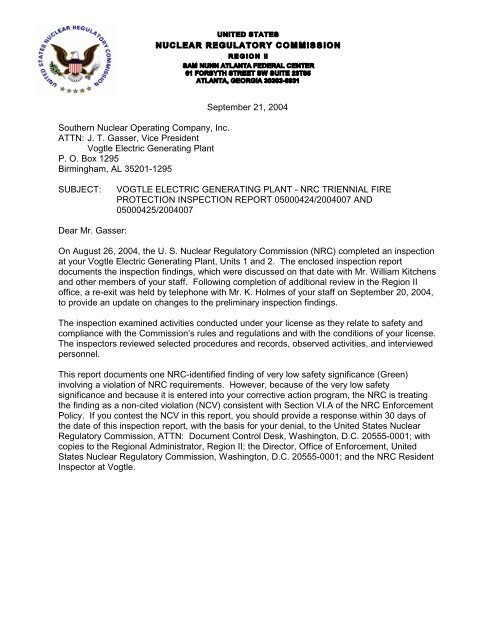
Southern Nuclear Operating Company, Inc.<br />
ATTN: J. T. Gasser, Vice President<br />
<strong>Vogtle</strong> Electric Generating Plant<br />
P. O. Box 1295<br />
Birmingham, AL 35201-1295<br />
September 21, 2004<br />
SUBJECT:<br />
VOGTLE ELECTRIC GENERATING PLANT - NRC TRIENNIAL FIRE<br />
PROTECTION INSPECTION REPORT 05000424/2004007 AND<br />
05000425/2004007<br />
Dear Mr. Gasser:<br />
On August 26, 2004, the U. S. Nuclear Regulatory Commission (NRC) <strong>com</strong>pleted an inspection<br />
at your <strong>Vogtle</strong> Electric Generating Plant, Units 1 and 2. The enclosed inspection report<br />
documents the inspection findings, which were discussed on that date with Mr. William Kitchens<br />
and other members of your staff. Following <strong>com</strong>pletion of additional review in the Region II<br />
office, a re-exit was held by telephone with Mr. K. Holmes of your staff on September 20, 2004,<br />
to provide an update on changes to the preliminary inspection findings.<br />
The inspection examined activities conducted under your license as they relate to safety and<br />
<strong>com</strong>pliance with the Commission’s rules and regulations and with the conditions of your license.<br />
The inspectors reviewed selected procedures and records, observed activities, and interviewed<br />
personnel.<br />
This report documents one NRC-identified finding of very low safety significance (Green)<br />
involving a violation of NRC requirements. However, because of the very low safety<br />
significance and because it is entered into your corrective action program, the NRC is treating<br />
the finding as a non-cited violation (NCV) consistent with Section VI.A of the NRC Enforcement<br />
Policy. If you contest the NCV in this report, you should provide a response within 30 days of<br />
the date of this inspection report, with the basis for your denial, to the United States Nuclear<br />
Regulatory Commission, ATTN: Document Control Desk, Washington, D.C. 20555-0001; with<br />
copies to the Regional Administrator, Region II; the Director, Office of Enforcement, United<br />
States Nuclear Regulatory Commission, Washington, D.C. 20555-0001; and the NRC Resident<br />
Inspector at <strong>Vogtle</strong>.
SNC 2<br />
In accordance with 10 CFR 2.390 of the NRC’s “Rules of Practice,” a copy of this letter<br />
and its enclosure will be available electronically for public inspection in the NRC Public<br />
Document Room or from the Publicly Available Records (PARS) <strong>com</strong>ponent of NRC’s<br />
document system (ADAMS). ADAMS is accessible from the NRC Web site at<br />
http://www.nrc.gov/reading-rm/adams.html (the Public Electronic Reading Room).<br />
Sincerely,<br />
Docket Nos.: 50-424, 50-425<br />
License Nos.: NPF-68, NPF-81<br />
/RA/<br />
Charles R. Ogle, Chief<br />
Engineering Branch 1<br />
Division of Reactor Safety<br />
Enclosure: Inspection Report 05000424/2004007 and 05000425/2004007<br />
w/Attachment: Supplemental Information<br />
cc w/encl:<br />
J. T. Gasser<br />
Executive Vice President<br />
Southern Nuclear Operating Company, Inc.<br />
Electronic Mail Distribution<br />
W. F. Kitchens<br />
General Manager, Plant <strong>Vogtle</strong><br />
Southern Nuclear Operating Company, Inc.<br />
Electronic Mail Distribution<br />
N. J. Stringfellow<br />
Manager-Licensing<br />
Southern Nuclear Operating Company, Inc.<br />
Electronic Mail Distribution<br />
Director, Consumers' Utility Counsel Division<br />
Governor's Office of Consumer Affairs<br />
2 M. L. King, Jr. Drive<br />
Plaza Level East; Suite 356<br />
Atlanta, GA 30334-4600<br />
Office of the County Commissioner<br />
Burke County Commission<br />
Waynesboro, GA 30830<br />
(cc w/encl cont’d - See page 3)
SNC 3<br />
(cc w/encl cont’d)<br />
Director, Department of Natural Resources<br />
205 Butler Street, SE, Suite 1252<br />
Atlanta, GA 30334<br />
Manager, Radioactive Materials Program<br />
Department of Natural Resources<br />
Electronic Mail Distribution<br />
Attorney General<br />
Law Department<br />
132 Judicial Building<br />
Atlanta, GA 30334<br />
Laurence Bergen<br />
Oglethorpe Power Corporation<br />
Electronic Mail Distribution<br />
Resident Manager<br />
Oglethorpe Power Corporation<br />
Alvin W. <strong>Vogtle</strong> Nuclear Plant<br />
Electronic Mail Distribution<br />
Arthur H. Domby, Esq.<br />
Troutman Sanders<br />
Electronic Mail Distributioin<br />
Senior Engineer - Power Supply<br />
Municipal Electric Authority<br />
of Georgia<br />
Electronic Mail Distribution<br />
Reece McAlister<br />
Executive Secretary<br />
Georgia Public Service Commission<br />
244 Washington Street, SW<br />
Atlanta, GA 30334<br />
Distribution w/encl: See page 4
SNC 4<br />
Distribution w/encl:<br />
C. Gratton, NRR<br />
C. Evans (Part 72 Only)<br />
L. Slack, RII EICS<br />
RIDSNRRDIPMLIPB<br />
PUBLIC<br />
OFFICE DRS/RII DRS/RII DRS/RII DRS/RII DRS/RII DRS/RII DRS/RII<br />
SIGNATURE RA RA RA RA RA<br />
NAME MERRIWEATHE G. WISEMAN P. FILLION O’DONOHUE B. BONSER<br />
DATE 09/20/2004 09/20/2004 09/21/2004 09/16/2004 09/16/2004 09/XX/2004 09/XX/2004<br />
E-MAIL COPY? YES NO YES NO YES NO YES NO<br />
PUBLIC DOCUMENT YES NO<br />
OFFICIAL RECORD COPY DOCUMENT NAME: C:\ORPCheckout\FileNET\ML042650400.wpd
U. S. NUCLEAR REGULATORY COMMISSION<br />
REGION II<br />
Docket Nos.: 50-424, 50-425<br />
License Nos.:<br />
NPF-68, NPF-81<br />
Report Nos.: 05000424/2004007 and 05000425/2004007<br />
Licensee:<br />
Southern Nuclear Operating Company, Inc. (SNC)<br />
Facility:<br />
<strong>Vogtle</strong> Electric Generating Plant<br />
Location:<br />
7821 River Road<br />
Waynesboro, GA 30830<br />
Dates: August 9 - 13, 2004 (Week 1)<br />
August 23 - 26, 2004 (Week 2)<br />
Inspectors:<br />
K. O’Donohue, Fire Protection Team Leader<br />
N. Merriweather, Sr. Reactor Inspector (Team Lead)<br />
P. Fillion, Reactor Inspector<br />
G. Wiseman, Sr. Reactor Inspector<br />
Ac<strong>com</strong>panying G. Cameron, Fire Protection Co-op (Week 1)<br />
Personnel:<br />
Approved by:<br />
Charles R. Ogle, Chief<br />
Engineering Branch 1<br />
Division of Reactor Safety<br />
Enclosure
SUMMARY OF FINDINGS<br />
IR 05000424/2004-007, 05000425/2004-007; 08/09 -13/2004 and 08/23 - 26/2004; <strong>Vogtle</strong><br />
Electric Generating Plant, Units 1 and 2; Triennial Fire Protection.<br />
The report covered an announced two-week period of inspection by four regional inspectors.<br />
One Green non-cited violation was identified. The significance of most findings is indicated by<br />
their color (Green, White, Yellow, or Red) using Inspection Manual Chapter (IMC) 0609,<br />
“Significance Determination Process” (SDP). Findings for which the SDP does not apply may<br />
be Green or be assigned a severity level after management review. The NRC’s program for<br />
overseeing the safe operation of <strong>com</strong>mercial nuclear power reactors is described NUREG-<br />
1649, “Reactor Oversight Process,” Revision 3, dated July 2000.<br />
A. NRC-Identified and Self-Revealing Findings<br />
Cornerstone: Mitigating Systems<br />
• Green. A non-cited violation of Operating License Condition 2.G, was identified for<br />
an inadequate fire brigade fire fighting pre-plan. The pre-plan was inadequate in that<br />
it gave instructions for the fire brigade to vent smoke and hot gases into an area that<br />
the operators needed to access to perform local manual actions. Specifically, the fire<br />
fighting pre-plan (92773-2) for Fire Zone (FZ) 73 of the Control Building directed the<br />
fire brigade to vent smoke and hot gases out of the fire area (FZ 73) into room RB-33<br />
(FZ 80). However, RB-33 is the only available route for an operator to enter room RB-<br />
29. The operator is required to enter room RB-29 during a fire in FZ 73 in order to<br />
perform local manual actions to prevent spurious opening of pressurizer power<br />
operated relief valve (PORV) PV-0455A. If the fire brigade had vented smoke and<br />
toxic gases into RB-33, it could have resulted in a failure to prevent spurious opening<br />
of PORV PV-0455A. Upon identification, the licensee revised the fire fighting preplan<br />
(92773-2) to vent the smoke into a stairwell rather than room RB-33.<br />
This finding is greater than minor because it is associated with the protection against<br />
external factors attribute and degraded the reactor safety mitigating systems<br />
cornerstone objective, in that movement of smoke and hot toxic gases as directed<br />
could prohibit operator access to equipment that was supposed to remain unaffected<br />
by a particular fire. This finding was determined to be of very low safety significance<br />
because other fire protection features, such as passive fire barriers, automatic fire<br />
suppression, and safe shutdown capability from the main control room were still<br />
available. (Section 1R05.02)<br />
B. Licensee-Identified Violations<br />
None.
REPORT DETAILS<br />
1. REACTOR SAFETY<br />
Cornerstones: Initiating Events, Mitigating Systems and Barrier Integrity<br />
1R05<br />
Fire Protection<br />
The purpose of this inspection was to review the <strong>Vogtle</strong> Electric Generating Plant<br />
(VEGP) fire protection program (FPP) for selected risk-significant fire areas. Emphasis<br />
was placed on verification that the post-fire safe shutdown (SSD) capability and the fire<br />
protection features provided for ensuring that at least one redundant train of SSD<br />
systems is maintained free of fire damage. The inspection was performed in<br />
accordance with the U. S. Nuclear Regulatory Commission’s (NRC) Reactor Oversight<br />
Process using a risk-informed approach for selecting the fire areas and attributes to be<br />
inspected. The inspectors used the licensee’s Individual Plant Examination for External<br />
Events (IPEEE) and in-plant tours to choose three risk-significant fire areas for detailed<br />
inspection and review. The fire areas (zones) chosen for review during this inspection<br />
were:<br />
• Fire Area 1-AB-LD-B, Fire Zone (FZ) 38, Unit 1 Auxiliary Building Level A. This area<br />
contains 2- and 3-hour fire barriers. This area involves shutdown from the control<br />
room using safe shutdown train B. Also limited use of the remote shutdown panel<br />
may be required.<br />
• Fire Area 1-CB-LC-A, FZ 42B, Unit 1 Control Building and Fueling Handling Building,<br />
Level A, B, and C. This area contains 3 hour barriers. This area involves shutdown<br />
from the control room using safe shutdown train B.<br />
• Fire Area 2-CB-LB-A, FZ 73, Unit 2 Control Building Level B. This fire area contains<br />
2- and 3-hour fire barriers. This area involves a shutdown from the control room using<br />
safe shutdown train B. Potential fire damage to the reactor trip breakers may<br />
necessitate ensuring a reactor trip by some other means.<br />
The inspectors evaluated the licensee’s FPP against applicable requirements, including<br />
Operating License Condition 2.G; Title 10 of the Code of Federal Regulations, Part<br />
50.48; <strong>com</strong>mitments to Branch Technical Position (BTP) Chemical and Mechanical<br />
Engineering Branch (CMEB) 9.5-1; VEGP Updated Final Safety Analysis Report<br />
(UFSAR); related NRC safety evaluation reports (SERs) documented in NUREG 1137<br />
including all applicable supplements; and plant Technical Specifications. The inspectors<br />
evaluated all areas of this inspection, as documented below, against these<br />
requirements.<br />
Specific documents reviewed by the inspectors are listed in the attachment.
.01 Systems Required to Achieve and Maintain Post-Fire Safe Shutdown<br />
a. Inspection Scope<br />
2<br />
The licensee’s fire hazard analysis (FHA) described in the UFSAR for each plant area<br />
includes an evaluation of safe shutdown capability given a fire in that particular area.<br />
The evaluation identifies which safe shutdown train (A or B) is to be used in the event of<br />
a fire in an area or in a zone of that area. The evaluation also identifies the possible<br />
spurious actuations that can result from a fire in each area. Actions to over<strong>com</strong>e the<br />
spurious operations or <strong>com</strong>pensatory measures taken are described in the plant<br />
procedures.<br />
The licensee’s safe shutdown analysis (SSA) was reviewed by the inspectors to<br />
determine the <strong>com</strong>ponents and systems necessary to achieve and maintain SSD<br />
conditions from the main control room (MCR) in the event of fire in FZs 38, 42B, and 73.<br />
The objectives of this evaluation were to:<br />
• Verify that the licensee’s shutdown methodology had correctly identified the<br />
<strong>com</strong>ponents and systems necessary to achieve and maintain an SSD condition.<br />
• Confirm the adequacy of the systems selected for reactivity control, reactor coolant<br />
makeup, reactor heat removal, process monitoring, and support system functions.<br />
• Verify that an SSD can be achieved and maintained without off-site power when it can<br />
be confirmed that a postulated fire in any of the selected fire areas could cause the<br />
loss of off-site power.<br />
• Verify that local manual operator actions are consistent with the plant’s fire protection<br />
licensing basis.<br />
The inspectors performed sufficient inspection activity to verify that the licensee’s<br />
shutdown methodology had properly identified the <strong>com</strong>ponents and systems necessary<br />
to achieve and maintain safe shutdown conditions. All of the shutdown functions were<br />
addressed to some extent with more emphasis placed on reactor coolant system<br />
inventory control, reactor coolant pump seal protection, and secondary side isolation.<br />
Of the fire areas chosen, the licensee’s analysis concluded that cable damage would not<br />
lead to a loss of offsite power. The IPEEE assumed a loss of offsite power in Fire Area<br />
1-AB-LD-B; however, further investigation by the team determined that there was no<br />
fire-induced mechanism to cause a loss of offsite power associated with this area. The<br />
team reviewed the routing of cables associated with one of the reserve auxiliary<br />
transformer differential relays (current transformer and trip circuit) to independently<br />
check that the licensee’s conclusions regarding loss of offsite power were correct.<br />
b. Findings<br />
No findings of significance were identified.
.02 Fire Protection of Safe Shutdown Capability<br />
a. Inspection Scope<br />
3<br />
For the selected fire areas/zones, the inspectors evaluated the potential for fires, the<br />
<strong>com</strong>bustible fire load characteristics, potential exposure fire severity, the separation of<br />
systems necessary to achieve safe shutdown, and the separation of electrical<br />
<strong>com</strong>ponents and circuits to ensure that at least one safe shutdown path was free of fire<br />
damage. The inspectors reviewed selected portions of the UFSAR Section 9.5.1, Fire<br />
Protection Program, Appendix 9A, Fire Hazards Analysis, and Appendix 9B,<br />
Comparison of VEGP Units 1 and 2 with Requirements of the BTP CMEB 9.5-1. This<br />
review was conducted to determine if the licensee’s <strong>com</strong>mitments, as established in the<br />
fire protection licensing basis documents, were satisfied.<br />
The inspectors reviewed the licensee’s documents which establish and implement<br />
controls and practices to prevent fires and to control the storage of permanent and<br />
transient <strong>com</strong>bustible materials and ignition sources, to verify that the objectives<br />
established by the NRC-approved fire protection program were satisfied. The<br />
documents reviewed are listed in the attachment.<br />
The inspectors reviewed the basic layout of the plant and raceway system to verify that<br />
it provided good physical separation of redundant circuits, therefore limiting the<br />
possibility that redundant circuits would be routed in the same fire zone. For example,<br />
there were two separate main control room termination cabinet/cable spreading rooms,<br />
one below the control room for Train A cables and one above the control room for Train<br />
B cables. In addition, the team walked down the selected fire zones to look for cases of<br />
redundant cables routed in the same zone.<br />
The inspectors toured the selected plant fire areas/zones to observe: (1) the material<br />
condition of fire protection systems and equipment, (2) the storage of permanent and<br />
transient <strong>com</strong>bustible materials, and (3) the licensee’s implementation of the<br />
programmatic procedures for limiting fire hazards, <strong>com</strong>bustible waste collection,<br />
housekeeping practices, and cleanliness conditions. These reviews were ac<strong>com</strong>plished<br />
to ensure that the licensee was maintaining the fire protection systems, had properly<br />
evaluated in-situ <strong>com</strong>bustible fire loads, controlled hot-work activities, and limited<br />
transient fire hazards in a manner consistent with the UFSAR, administrative procedures<br />
and other fire protection program procedures. In addition, the inspectors reviewed<br />
design control procedures to determine if plant changes were adequately evaluated for<br />
the potential impact on the fire protection program, safe shutdown equipment, and plant<br />
procedures (as required by the fire protection program).<br />
The inspectors reviewed operator and fire brigade staffing, fire brigade response, fire<br />
brigade qualification training and drill program procedures, and fire brigade drill critiques<br />
for brigade shifts from January 2002, to August 2004. The reviews were performed to<br />
determine whether fire brigade drills had been conducted in high fire risk plant areas<br />
and whether fire brigade personnel training, qualifications, manning assignments, drill<br />
response, and performance met the requirements of the fire protection program.
4<br />
The inspectors walked down the primary and secondary fire emergency equipment<br />
storage locker locations and dress-out areas to evaluate equipment accessibility and<br />
functionality. The inspectors inspected the fire brigade’s protective ensembles, selfcontained<br />
breathing apparatus (SCBA), smoke control equipment, and various fire<br />
brigade equipment to determine operational readiness for fire fighting. The fire brigade<br />
self-contained breathing apparatuses were reviewed for adequacy as well as the<br />
availability of supplemental breathing air bottles and the capability to refill these bottles.<br />
The inspectors reviewed fire fighting pre-fire plans and fire response procedures for the<br />
selected fire areas/zones to determine if appropriate information was provided to fire<br />
brigade members to identify safe shutdown equipment and to facilitate suppression of<br />
an exposure fire that could impact safe shutdown capability. The inspectors walked<br />
down the selected fire areas/zones to <strong>com</strong>pare the associated pre-fire plans and<br />
drawings with as-built plant conditions and fire response procedures. This was done to<br />
verify that fire fighting pre-fire plan instructions and drawings were consistent with the<br />
fire protection features and potential fire conditions described in the fire hazards<br />
analysis. The inspectors also evaluated whether the fire response procedures and preplans<br />
for the selected fire areas/zones could be implemented as intended.<br />
The inspectors performed a review of flow diagrams and flooding analysis calculations,<br />
for fire suppression-caused flooding associated with the Unit 2 control building floor<br />
drains. This review focused on ensuring that those local manual operator actions<br />
required for normal redundant train main control room shutdown performed outside the<br />
control room would not be inhibited by the effects of the fire event, fire brigade activities,<br />
or fire suppression systems within the fire areas/zones or from an adjacent plant<br />
area/zone.<br />
b. Findings<br />
Introduction: The inspectors identified a Green non-cited violation (NCV) of <strong>Vogtle</strong><br />
Electric Generating Plant Unit 2 Operating License Condition 2.G, for an inadequate fire<br />
fighting pre-plan procedure. The fire fighting pre-plan procedure, 92773-2, Zone 73 -<br />
Unit 2 Control Building - Level B Fire Fighting Preplan, Rev. 0.1, did not have adequate<br />
instructions to the fire fighters on how to both remove smoke and toxic gases from the<br />
fire affected area and maintaining acceptable environmental conditions for operator<br />
access and egress routes to equipment, in some circumstances.<br />
Description: The inspectors evaluated whether the fire response procedures and fire<br />
fighting pre-plans for the selected fire area/zones could be implemented as intended.<br />
The inspectors noted that the fire fighting pre-plans directed stopping the heating,<br />
ventilation, and air conditioning system (HVAC) fan for the area of the fire and then<br />
using fire brigade portable fans for smoke removal from the affected room. Installed<br />
ventilation systems are then used to remove the smoke from the building. Step 4.3 of<br />
the fire fighting pre-plan procedure 92773-2 for FZ 73, directed smoke to be moved into<br />
switchgear room RB-33 (FZ 80) and control room personnel be notified to initiate smoke<br />
removal actions of procedure 13304-C, Control Building Normal HVAC System. The<br />
inspectors observed that 17103A-C, Annunciator Response Procedures For Fire Alarm<br />
Computer, Rev. 15.1, step 1e, directs an operator to close pressurizer PORV PV-<br />
0455A, by opening a breaker in room RB-29 in response to a fire in FZ 73. The only
5<br />
available route to RB-29 is through room RB-33. The actions to prevent spurious PORV<br />
opening could be inhibited due to the presence of smoke and hot toxic gases moved<br />
into RB-33 per 92773-2 smoke removal direction.<br />
In response to this issue, the licensee wrote Condition Report (CR) 2004003416 and<br />
made a prompt change to 92773-2, " Zone 73 - Control Building - Level B Fire Fighting<br />
Preplan," to direct smoke into a stairwell rather than room RB-33.<br />
Analysis: The finding is greater than minor because it is associated with the protection<br />
against external factors attribute and degraded the reactor safety mitigating systems<br />
cornerstone objective, in that movement of smoke and hot toxic gases as directed could<br />
prohibit operator access to equipment that was supposed to remain unaffected by a<br />
particular fire. The finding was screened using Phase 1 of Appendix F of Manual<br />
Chapter 0609. The inspectors calculated the average smoke and hot gas temperature<br />
within FZ 73 to be approximately 220 EF. This temperature is sufficient to activate<br />
sprinklers and fire dampers but would not likely challenge the 3-hour rated walls, doors<br />
or penetration seal barriers between FZ 73 and room RB-33. This temperature is<br />
significantly less than the temperature required for thermoset cables to be damaged (the<br />
type of cables used at VEGP). Based on these results, the inspectors determined this<br />
finding to be of very low safety significance (Green) because other area fire protection<br />
features, such as passive fire barriers, automatic fire suppression, and safe shutdown<br />
capability from the main control room were still available. In addition, the smoke and hot<br />
gas layer was calculated to be approximately 5 feet from the ceiling which would allow<br />
the fire brigade visibility to locate the fire source and initiate a fire fighting attack without<br />
evacuating smoke from the room. Thus, there was a low probability of occurrence of a<br />
fire that could require movement of smoke by the fire brigade. A Phase 2 assessment<br />
was not required.<br />
Enforcement: <strong>Vogtle</strong> Electric Generating Plant Unit 2 Operating License Condition 2.G,<br />
requires the licensee to implement and maintain the provisions of their NRC-approved<br />
fire protection program as described in the UFSAR for the facility. UFSAR Appendix 9B,<br />
Section C.1.e.n, states that the fire fighting procedures contain instructions to the fire<br />
fighters and operators. Inherent in this requirement is that the instructions must be<br />
appropriate and adequate.<br />
Contrary to the above, fire fighting pre-plan procedure, 92773-2, Zone 73 - Unit 2<br />
Control Building - Level B Fire Fighting Preplan, Rev. 0.1 was inadequate because it did<br />
not maintain a sufficient environment for operators to access required safe shutdown<br />
equipment. Because the finding is of very low safety significance, was entered into the<br />
corrective action program (CR 2004003416), and was corrected during the inspection<br />
period, this violation is being treated as an NCV, consistent with Section VI.A of the<br />
NRC Enforcement Policy: NCV 05000425/2004007-001, Inadequate Fire Protection Prefire<br />
Plan to Maintain Adequate Environmental Conditions for Operators to Access<br />
Required Equipment.
.03 Post-fire Safe Shutdown Circuit Analysis<br />
a. Inspection Scope<br />
6<br />
On a sample basis, the inspectors evaluated the adequacy of separation provided for<br />
electrical cables of safe shutdown systems. The inspectors also reviewed relevant<br />
portions of three Fire Event Safe Shutdown Evaluations, which contained the licensee’s<br />
safe shutdown analysis for the selected fire areas. The reports reviewed are listed in<br />
the attachment. The analysis intended to show that fire damage to <strong>com</strong>ponents and<br />
cables located within the chosen fire areas would not prevent safe shutdown. The<br />
inspectors then focused on any cases of redundant shutdown circuits routed in the<br />
same fire area.<br />
The inspectors made a detailed review of selected control circuits as listed in the<br />
attachment. Cables that could interfere with safe shutdown if they were routed in the<br />
selected fire areas were identified. The inspectors then evaluated the routing of these<br />
cables by reviewing the <strong>com</strong>puterized cable schedule which indicated the specific<br />
raceways through which the cables were routed together with the fire zone information.<br />
The inspectors pin-pointed the location of raceways in the field as necessary to<br />
determine if they could be in the zone of influence of fire emanating from transient<br />
<strong>com</strong>bustibles or in-situ fire sources.<br />
The inspectors also reviewed a sample of electrical coordination studies to verify that<br />
fire induced faults in load cables emanating from required sources of electric power<br />
would not cause a loss of power and prevent safe shutdown. Selective coordination for<br />
ground faults on the 4160 V system was checked for the following relays: 151NRB<br />
(transformer 1XNRB neutral), 151G (at in<strong>com</strong>ing breaker to bus 1BA03) and 150/151GF<br />
(at feeder breaker to load center 1NB10). The inspectors examined the installed relay<br />
setpoints as well as the last <strong>com</strong>pleted calibration records to verify that the relays were<br />
installed in accordance with design documents.<br />
b. Findings<br />
No findings of significance were identified.<br />
.04 Alternative Shutdown Capability and Operational Implementation of Alternative<br />
Shutdown<br />
a. Inspection Scope<br />
Alternative shutdown capability and operational implementation of alternative shutdown<br />
from outside the main control room was not examined during this inspection. This is<br />
because the selected fire zones (i.e., 38, 42B, and 73) are train B shutdown areas using<br />
the controls in the main control room, for the most part, with limited local manual<br />
actions. Manual operations using the train B remote shutdown panel were reviewed as<br />
related to fire response for FZ 38. The ability to perform the local manual actions, the<br />
access and egress routes for the operators, emergency lighting, and environmental<br />
conditions at the remote locations was examined by the team and discussed in other<br />
sections of the report.
7<br />
b. Findings<br />
No findings of significance were identified.<br />
.05 Communications<br />
a. Inspection Scope<br />
The inspectors reviewed plant <strong>com</strong>munication capabilities to evaluate the availability of<br />
the <strong>com</strong>munication systems to support fire event notification, fire brigade fire fighting<br />
activities, and plant personnel in the performance of manual operator actions to achieve<br />
and maintain a safe shutdown condition. The inspectors reviewed the fixed plant<br />
<strong>com</strong>munications systems (telephone/page) for use during safe shutdown, as credited in<br />
UFSAR Section 9.5.2. The inspectors also reviewed the use of the portable radio<br />
system for use during fire fighting activities. Both fixed and portable <strong>com</strong>munication<br />
systems were reviewed for the impact of any damage which could result from fires in the<br />
selected fire areas/zones on the functions the systems were intended to support, and to<br />
ensure that the design of the systems was adequate to support operator and fire<br />
brigade actions, as applicable. In addition, the inspectors reviewed <strong>com</strong>pleted fire<br />
brigade drill critique reports for brigade shifts from January 2002 to December 2003, to<br />
assess proper operation and effectiveness of the fire brigade <strong>com</strong>mand post portable<br />
radio <strong>com</strong>munications during fire drills and identify any history of operational or<br />
performance problems with radio <strong>com</strong>munications during fire drills.<br />
b. Findings<br />
No findings of significance were identified.<br />
.06 Emergency Lighting<br />
a. Inspection Scope<br />
The inspectors reviewed the design, placement, operation, and periodic testing<br />
procedures for direct current (DC) self-contained battery powered emergency lighting<br />
units (ELU) and dedicated, battery powered portable ELUs. The inspectors evaluated<br />
the capability of the ELUs to support plant personnel in the performance of SSD<br />
functions, including local manual operator actions, and for illuminating access and<br />
egress routes to the areas where those manual actions would be performed. The<br />
inspectors checked that these battery power supplies were rated with at least an 8-hour<br />
capacity, as required by BTP CMEB 9.5-1, Section C.5.g (1). In plant areas where<br />
operators perform local manual actions, the inspectors inspected area ELUs for proper<br />
operation and checked the aiming of lamp heads to determine if sufficient illumination<br />
would be available to adequately illuminate the SSD equipment, the equipment<br />
identification tags, and the access and egress routes thereto. The inspectors also<br />
reviewed <strong>com</strong>pleted surveillance and maintenance procedures and test records to<br />
ensure that the licensee properly maintained the lighting equipment.
8<br />
The inspectors observed whether emergency exit lighting was provided for personnel<br />
evacuation pathways to the outside exits as identified in the National Fire Protection<br />
Association (NFPA) 101, Life Safety Code, and the Occupational Safety and Health<br />
Administration (OSHA) Part 1910, Occupational Safety and Health Standards. This<br />
review also included examination of whether backup emergency lighting was provided<br />
for the primary and secondary fire emergency equipment storage locker locations and<br />
dress-out areas in support of fire brigade operations should power fail during a fire<br />
emergency.<br />
b. Findings<br />
No findings of significance were identified.<br />
.07 Cold Shutdown Repairs<br />
a. Inspection Scope<br />
The team considered whether any repairs may be needed to achieve cold shutdown<br />
associated with the fire areas selected (i.e., FZs 38, 42B, and 73). This review was<br />
ac<strong>com</strong>plished by reviewing the list of cold shutdown repair procedures and the list of<br />
shutdown related cables and their associated equipment known to be in the selected fire<br />
zones.<br />
b. Findings<br />
No findings of significance were identified.<br />
.08 Fire Barriers and Fire Area/Zone/Room Penetration Seals<br />
a. Inspection Scope<br />
The inspectors reviewed the selected fire areas/zones to evaluate the adequacy of the<br />
fire resistance of fire areas/zones barrier enclosure walls, ceilings, floors, fire barrier<br />
mechanical and electrical penetration seals, fire doors, fire dampers, and electrical<br />
raceway fire barrier systems. The review was performed to ensure that at least one<br />
train of safe shutdown equipment was free of fire damage. This was ac<strong>com</strong>plished by<br />
observing the material condition and configuration of the installed fire barrier features,<br />
as well as reviewing construction details and supporting fire endurance tests for the<br />
installed fire barrier features, to verify that the as-built configurations were qualified by<br />
appropriate fire endurance tests. The inspectors also reviewed selected fire seals<br />
identified in the plant against supporting fire tests to ensure the installed seals were<br />
bounded by tested configurations and that fire barrier installations met licensing basis<br />
<strong>com</strong>mitments. The inspectors also reviewed the FHA to verify the fire loading used by<br />
the licensee to determine the fire resistance rating of the fire barrier enclosures. The fire<br />
protection features included in the review are listed in the attachment.
9<br />
b. Findings<br />
No findings of significance were identified.<br />
.09 Fire Protection Systems, Features and Equipment<br />
a. Inspection Scope<br />
The inspectors reviewed safe shutdown calculations, vendor documentation, flow<br />
diagrams, cable routing information, system operating instructions, operational valve<br />
lineup procedures, and system availability studies associated with the fire pumps and<br />
fire protection water supply system. Using operating and test procedures, the<br />
inspectors toured selected fire pumps and portions of the fire main piping system to<br />
evaluate material condition, consistency of as-built configurations with engineering<br />
drawings, and to verify correct system breaker and valve lineups. The inspectors<br />
evaluated the <strong>com</strong>mon fire protection water delivery and supply <strong>com</strong>ponents to assess if<br />
they could be damaged or inhibited by fire-induced failures of electrical power supplies<br />
or control circuits. In addition, the inspectors reviewed periodic surveillance and<br />
operability flow test data for the fire pumps and fire main loop to assess whether the test<br />
program was sufficient to validate proper operation of the fire protection water supply<br />
system in accordance with those design requirements and acceptance criteria specified<br />
in procedure 92040-C, “Fire Protection Operability and LCO Requirements,” and the<br />
UFSAR.<br />
For the selected fire areas/zones, the inspectors reviewed the adequacy of the design,<br />
installation, and operation of the automatic detection and alarm system to actuate in the<br />
early stage of a fire. The review included walk downs of the systems and an<br />
examination of the types of detectors, detector spacing, the licensee’s technical<br />
evaluation of the detector locations, and the ceiling, steel beam reinforcing plans to<br />
assess whether the areas were protected by fire detectors in accordance with the Code<br />
of Record requirements (National Fire Protection Association 72E, 1982). The<br />
inspectors also reviewed the licensee’s submittals and associated NRC SERs for the<br />
selected fire areas/zones to ensure that the fire detection systems for the selected fire<br />
areas were installed in accordance with the design and licensing bases of the plant.<br />
Additionally, the inspectors reviewed fire detection surveillance procedures and the<br />
detection system technical requirements specified in Procedure 92040-C to determine<br />
the adequacy of fire detection <strong>com</strong>ponent testing to ensure that the detection systems<br />
could function when needed.<br />
The inspectors reviewed engineering drawings for the automatic fire suppression<br />
systems to assess the adequacy of the design and installations in the Control Building<br />
(Level B, FZ 73) and Auxiliary Building (Level A, FZ 38). The inspectors walked down<br />
the areas to observe the placement and spacing of sprinkler heads and to confirm they<br />
were not obstructed. Design calculations were reviewed to verify that the required fire<br />
hose water flow and sprinkler system density for these areas was available. In addition,<br />
the inspectors reviewed a sample of electrical schematics and cable routing information<br />
for automatic fire suppression equipment to assess the potential effects of fire-induced<br />
spurious system operation or malfunction on safe shutdown manual operator actions in<br />
adjacent plant areas.
10<br />
The inspectors reviewed the manual suppression standpipe and fire hose system to<br />
verify adequate design, installation, and operation in the selected fire areas/zones. The<br />
inspectors examined flow measurement/pressure test data to verify that sufficient<br />
pressure and flow volume was available to produce electrically safe and effective fire<br />
hose operation within the nozzle manufacturer’s specified flow range. During plant<br />
tours, the inspectors observed placement of the fire hoses and extinguishers to verify<br />
they were not blocked and were consistent with the fire fighting pre-plan drawings and<br />
fire protection program documents. Additionally, the inspectors checked a sample of<br />
fire hose lengths to confirm they could reach the affected fire areas/zones in support of<br />
manual fire fighting efforts.<br />
b. Findings<br />
No findings of significance were identified.<br />
.10 Compensatory Measures<br />
a. Inspection Scope<br />
The inspectors reviewed the administrative controls for out-of-service, degraded, and/or<br />
inoperable, fire protection features. The inspectors reviewed selected active items on<br />
the fire protection “LCO tracking log” and <strong>com</strong>pared them with the fire areas selected for<br />
inspection. The <strong>com</strong>pensatory measures that had been established in these areas were<br />
<strong>com</strong>pared to those specified in procedure 92040-C to verify that the risk associated with<br />
removing fire protection from service was properly assessed and adequate<br />
<strong>com</strong>pensatory measures were implemented in accordance with the approved fire<br />
protection program. Additionally, the inspectors reviewed the adequacy of the licensee’s<br />
short term <strong>com</strong>pensatory measures for a degraded function or feature until appropriate<br />
corrective actions were taken.<br />
b. Findings<br />
No findings of significance were identified.<br />
.11 Fire Protection Licensing Basis<br />
a. Inspection Scope<br />
The team reviewed licensing basis documents, including: 10 CFR 50.48; BTP CMEB<br />
9.5-1; Operating License Condition 2.G; the UFSAR; and fire protection SERs<br />
documented in NUREG 1137 and its supplements. Based on the above, the inspectors<br />
evaluated and <strong>com</strong>pared the licensee’s safe shutdown procedures, and various<br />
calculations of record against the licensing basis to measure the adequacy and<br />
consistency of the program documentation.<br />
b. Findings<br />
No findings of significance were identified.
11<br />
4. OTHER ACTIVITIES<br />
4OA2 Identification and Resolution of Problems<br />
a. Inspection Scope<br />
The inspectors reviewed condition reports resulting from fire, smoke, sparks, arcing, and<br />
equipment overheating incidents for the period of July 31, 2001 to July 19, 2004 as well<br />
as selected fire brigade response, emergency / incidents, and fire safety inspection<br />
reports. This review was conducted to assess the frequency of fire incidents and<br />
effectiveness of the fire prevention program and any maintenance-related or material<br />
condition problems related to fire incidents. The inspectors also reviewed other<br />
corrective action program documents, including <strong>com</strong>pleted corrective actions<br />
documented in selected CRs, and operating experience program (OEP) documents to<br />
verify that industry-identified fire protection problems potentially or actually affecting<br />
VEGP were appropriately entered into, and resolved by, the corrective action program<br />
process. Items included in the OEP effectiveness review were NRC Information<br />
Notices, industry or vendor-generated reports of defects and non<strong>com</strong>pliance under 10<br />
CFR Part 21, and vendor information letters. In addition, the inspectors reviewed a<br />
sample of the fire protection program audits and self-assessments which the licensee<br />
performed in the previous two-year period. The inspectors evaluated the effectiveness<br />
of the corrective actions for the identified issues. The documents reviewed are listed in<br />
the attachment.<br />
b. Findings<br />
No findings of significance were identified.<br />
4OA6 Meetings, Including Exit<br />
On August 26, 2004, the lead inspector presented the inspection results to<br />
Mr. W. Kitchens and other members of his staff who acknowledged the findings. The<br />
licensee confirmed that proprietary information was not provided or examined during the<br />
inspection. Following <strong>com</strong>pletion of additional review in the Region II office, a final exit<br />
was held by telephone with Mr. K. Holmes on September 20, 2004, to provide an update<br />
on changes to the preliminary inspection findings. The licensee acknowledged the<br />
findings.
SUPPLEMENTAL INFORMATION<br />
KEY POINTS OF CONTACT<br />
Licensee personnel:<br />
J. Dillon, Performance Analysis Engineer<br />
S. Douglas, Manager Operations<br />
K. Holmes, Performance Analysis Supervisor<br />
W. Kitchens, Nuclear Plant General Manager<br />
J. Lattner, Fire Protection Engineer<br />
B. Lewis, Plant Instructor<br />
K. Lowery, Senior Licensing Engineer<br />
L. Rains, Fire Protection System Engineer<br />
R. Reddy, Senior Engineer<br />
J. Robinson, Unit Superintendent Operations<br />
J. Seay, Senior Engineer<br />
G. Senicz, Senior Engineer<br />
T. Tidwell, Engineering Supervisor<br />
Other licensee employees contacted included office support, operations, engineering,<br />
maintenance, radiation, and corporate personnel.<br />
NRC personnel:<br />
G. McCoy, Senior Resident Inspector<br />
T. Morrissey, Resident Inspector<br />
W. Rodgers, Senior Risk Analyst, Region II<br />
LIST OF ITEMS OPENED, CLOSED, AND DISCUSSED<br />
Opened and Closed<br />
05000425/2004007-001 NCV Inadequate Fire Protection Pre-fire Plan to Ensure<br />
Adequate Environmental Conditions for Operators to<br />
Access Required Equipment (Section 1R05.02).<br />
Discussed<br />
None<br />
Attachment
LIST OF COMPONENTS INSPECTED<br />
Section 1R05.01: Post-fire Safe Shutdown Systems and<br />
Section 1R05.03: Post-fire Safe Shutdown Circuit Analysis<br />
Drawings<br />
1X3D-BD-C02F, Rev 9<br />
1X3D-BD-C02H, Rev 11<br />
2X3D-BD-C02F, Rev 5<br />
2X3D-BD-C02H, Rev 5<br />
1X3D-BD-C04L, Rev 6<br />
1X3D-BD-C04H, Rev 5<br />
1X3D-BD-C04J, Rev 6<br />
1X3D-BD-C04U, Rev 5<br />
2X3D-BD-C04L, Rev 6<br />
2X3D-BD-C04H, Rev 4<br />
2X3D-BD-C04J, Rev 4<br />
2X3D-BD-C04U, Rev 4<br />
1X3D-BD-L03H, Rev 8<br />
1X3D-BD-L03J, Rev 7<br />
2X3D-BD-L03H, Rev 4<br />
2X3D-BD-L03J, Rev 4<br />
2X3D-BD-C05G, Rev 2<br />
2X3D-BD-C05H Rev 5<br />
Description<br />
Elementary Diagram for 1LV-0112B (VCT outlet valve)<br />
Elementary Diagram for 1LV-0112D (RWST outlet valve)<br />
Elementary Diagram for 2LV-0112B (VCT outlet valve)<br />
Elementary Diagram for 2LV-0112D (RWST outlet valve)<br />
Elementary Diagram for 1HV-8103A (RCP seal injection valve)<br />
Elementary Diagram for 1HV-8103B (RCP seal injection valve)<br />
Elementary Diagram for 1HV-8103C (RCP seal injection valve)<br />
Elementary Diagram for 1HV-8103D (RCP seal injection valve)<br />
Elementary Diagram for 2HV-8103A (RCP seal injection valve)<br />
Elementary Diagram for 21HV-8103B (RCP seal injection valve)<br />
Elementary Diagram for 2HV-8103C (RCP seal injection valve)<br />
Elementary Diagram for 2HV-8103D (RCP seal injection valve)<br />
Elementary Diagram for 1HV-1978 (ACCS to RCP thermal barrier<br />
valve)<br />
Elementary Diagram for 1HV-1979 (ACCS to RCP thermal barrier<br />
valve)<br />
Elementary Diagram for 2HV-1978 (ACCS to RCP thermal barrier<br />
valve)<br />
Elementary Diagram for 2HV-1979 (ACCS to RCP thermal barrier<br />
valve)<br />
Elementary Diagram for 2HV-8095A & 8096A (Reactor head vent<br />
isolation valve)<br />
Elementary Diagram for 2HV-0442A (Reactor head vent<br />
modulation valve)<br />
Section 1R05.08: Fire Barriers and Penetration Seals<br />
Fire Wall Identification<br />
Removable Dry-stacked Block Wall<br />
Embedded Safe Shutdown Conduits<br />
Fire Door Identification<br />
12108L1A17<br />
12108L1A19<br />
Description<br />
Fire Zone 38, Unit 1 Auxiliary Building Level<br />
A, Room RA-50 to Room RA-07<br />
Fire Zone 38, Unit 1 Auxiliary Building Level<br />
A, Room RA-50 to Room RA-07<br />
Description<br />
Fire Zone 38, Unit 1 Auxiliary Building Level<br />
A, Held-open Fire Door to Unit 1 Room RA-<br />
24<br />
Fire Zone 38, Unit 1 Auxiliary Building Level<br />
A, Fire Door to Stairway #3<br />
Attachment
2<br />
12108L1A43<br />
12108L1A46<br />
12108L1A53<br />
12111L1B98<br />
22111L1B07<br />
22111L1B10<br />
22111L1B26<br />
22111L1B32<br />
Fire Damper Identification<br />
A-1532-315<br />
A-1532-316<br />
A-1533-314<br />
A-1532-351<br />
Fire Barrier Penetration Seal Identification<br />
V12108Z1097A<br />
V12108Z1089A<br />
V12111Z11526A<br />
V12111Z11527A<br />
V22111Z1009B<br />
V22111Z1012B<br />
V22111Z1026B<br />
V22111Z1472B<br />
Fire Zone 38, Unit 1 Auxiliary Building Level<br />
A, Fire Door to Unit 1 Room RA-51<br />
Fire Zone 38, Unit 1 Auxiliary Building Level<br />
A, Fire Door to Stairway #1<br />
Fire Zone 38, Unit 1 Auxiliary Building Level<br />
A, Fire Door to Unit 2 Room RA-89<br />
Fire Zone 42B, Unit 1 Control Building Level<br />
B, Airtight and Fire Door to Room RB-70<br />
Fire Zone 73, Unit 2 Control Building Level<br />
B, Fire Door Room RB-04 to Room RB-06<br />
Fire Zone 73, Unit 2 Control Building Level<br />
B, Fire Door Room RB-07 to Room RB-08<br />
Fire Zone 73, Unit 2 Control Building Level<br />
B, Fire Door Room RB-06 to Room RB-21<br />
Fire Zone 73, Unit 2 Control Building Level<br />
B, Fire Door Room RB-06 to Room RB-33<br />
Description<br />
Fire Zone 73, Unit 2 Control Building Level<br />
B, Room RB-06 to Room RB-33<br />
Fire Zone 73, Unit 2 Control Building Level<br />
B, Room RB-06 to Room RB-33<br />
Fire Zone 73, Unit 2 Control Building Level<br />
B, Room RB-06 to Room RB-33<br />
Fire Zone 69, Unit 2 Control Building Level<br />
B, Room RB-07 to Room RB-08<br />
Description<br />
Fire Zone 38, Unit 1 Auxiliary Building Level<br />
A, Seal to Unit 1 Room RA-51<br />
Fire Zone 38, Unit 1 Auxiliary Building Level<br />
A, Seal Room RA51 to Room RA-52<br />
Fire Zone 42B, Unit 1 Control Building Level<br />
A, Seal to Room RA-70<br />
Fire Zone 42B, Unit 1 Control Building Level<br />
A, Seal to Room RA-70<br />
Fire Zone 73, Unit 2 Control Building Level<br />
B, Seal Room RB-06 to Room RB-04<br />
Fire Zone 73, Unit 2 Control Building Level<br />
B, Seal Room RB-06 to Room RB-04<br />
Fire Zone 69, Unit 2 Control Building Level<br />
B, Seal Room RB-07 to Room RB-08<br />
Fire Zone 73, Unit 2 Control Building Level<br />
B, Seal Room RB-06 to Room RB-33<br />
Attachment
3<br />
Electrical Raceway Fire Barrier Systems<br />
Gypsum Wallboard Enclosure<br />
Description<br />
Fire Zone 80, Unit 2 Control Building Level<br />
B, ERFBS in Room RB-33 For Raceway<br />
2BE350TLAM<br />
Attachment
4<br />
LIST OF DOCUMENTS REVIEWED<br />
Procedures<br />
00056-C, 10 CFR50.59 Screenings and Evaluations, Rev. 21.1<br />
00253-C, Smoking, Eating, and Drinking Policy, Rev. 11.1<br />
00400-C, Plant Design Control, Rev. 36<br />
00705-C, Fire Protection Training Program, Rev. 13<br />
13302-1, Control Building ESF Ventilation System, Rev. 10.1<br />
14958-C, Fire Brigade Equipment Monthly Inspection, Rev. 15<br />
14961-C, Emergency Lighting Surveillance, Rev. 33<br />
17103A-C, Annunciator Response Procedures For Fire Alarm Computer, Rev. 15.1<br />
17103B-C, Annunciator Response Procedures For Fire Alarm Computer, Rev. 4<br />
19000-C, E-0 Reactor Trip or Safety Injection, Rev. 29<br />
19001-C, ES-0.1 Reactor Trip Response, Rev. 25.2<br />
29219-1, Fire and Smoke Detection Operational Test 1-1813-Q3-F19, Rev. 6<br />
92000-C, Fire Protection Program, Rev. 19.2<br />
92005-C, Fire Response Procedure, Rev. 20<br />
92010-C, Monthly Fire Inspection, Rev. 20.2<br />
92015-C, Use, Control, and Storage of Flammable/Combustible Materials, Rev. 26<br />
92027-C, Fire Watch Program, Rev. 15<br />
92030-C, Fire Drill Program, Rev. 12.1<br />
92040-C, Fire Protection Operability and LCO Requirements, Rev. 25<br />
92773-2, Zone 73 - Unit 2 Control Building - Level B Fire Fighting Preplan, Rev. 0.1<br />
92738-1, Zone 38 - Auxiliary Building - Level A Fire Fighting Preplan, Rev. 5<br />
92742B-1, Zone 42B - Control Building and Fuel Handling Building Electrical Tunnel and<br />
Electrical Shaft - Level C, B, and A Fire Fighting Preplan, Rev. 1.1<br />
Drawings<br />
AX1AG11-00075, Fire, Air &Water Seal, Silicone Foam, Floor/Wall, Rev.2<br />
AX1AG11-00123, Fire, Air &Water Seal, Elastomer, Floor/Wall, Rev.1<br />
AX1D11A15, Control Building Door Schedule, Rev. 14<br />
AX1D11A16, Control Building Door Schedule, Rev. 6<br />
AX1D11A27, Auxiliary Building Door Schedule, Rev. 10<br />
AX4DB176, Piping and Instrumentation Diagram (P&ID) Auxiliary Gas Systems, Rev. 19<br />
AX4DJ2106- Series, Control Bldg. HVAC Plan, Area 2A, Rev. 17<br />
AX4DJ2107- Series, Control Bldg. HVAC Plan, Area 2B, Rev. 20<br />
AX4DJ8015, Fire Areas, Auxiliary Building, Level A, Rev. 8<br />
AX4DJ8023, Fire Areas, Control Building, Level B, Rev. 10<br />
AX4DJ8025, Fire Areas, Control Building, El. 200’-0, Level A, Rev. 10<br />
AX4DJ8024- Series, Control Bldg. Fire Area Plans, Level A, Rev. 5<br />
CX5DT1101-64B, Instrument Set Point List, X4AS01, Rev. 3<br />
1X1D11H007, Control Building Penetration Seal, Level B, Rev.12<br />
1X1D11H010, Control Building Penetration Seal, Level A, Rev.9<br />
1X1D11J032, Control Building Penetration Seal, Level A, North Elevation, Rev.8<br />
1X3DJ013-A, Fire Detection Plan for Unit 1 Auxiliary Building Level A, Rev. 4<br />
Attachment
5<br />
1X4AX03-05350, Fire Protection Sprinkler System, Unit 1, Auxiliary Building Level A, Rev.3<br />
2X1D11J018, Control Building Penetration Seal, Level B, Rev.5<br />
2X1D11J021, Control Building Penetration Seal, Level B, Rev.4<br />
2X3DJ101-A, Fire Detection Plan for Unit 2 Control Building Level B, Rev. 3<br />
2X3DG361, Control Building Lighting and Communications, Plan El. 180’-0" Level B, Rev.8<br />
2X4DJ2103, Control Building HVAC Duct Layout, Plan Area 2A & 2D, El. 180’-0" - 200’-0"<br />
Level B, Rev. 18<br />
2X4DJ2103-1, Control Building HVAC Duct Layout, Plan Area 2A & 2E, El. 180’-0" - 200’-0"<br />
Level B, Rev.0<br />
2X4DJ2116-1, Control Building HVAC Duct Layout, Plan Area 2D & 2E, El. 180’-0" - 200’-0"<br />
Level B, Rev.14<br />
2X4DF2A207, Fire Protection Sprinkler System, Unit 2, Control Building Level B, Rev.3<br />
2X3DJ101-A, Fire Detection Plan for Control Building Level B, Unit 2, Rev. 3<br />
2X3DJ101-C, Fire Detection Plan for Control Building Level B, Unit 2, Rev. 2<br />
1X4DB208, Piping and Instrumentation Diagram (P&ID) Auxiliary Building Ventilation System,<br />
Rev. 11<br />
2X4DB210, P&ID Control Bldg. Normal HVAC System, Rev. 9<br />
1/2X4DB174- Series, P&ID - Fire Protection -Water System No. 2301, Rev. 18<br />
2X4DB210, P&ID - Control Building Normal HVAC System No. 1533, Rev. 9<br />
1X4DB138-1, P&ID Auxiliary Component Cooling Water System, Rev. 29<br />
1X4DB138-2, P&ID Auxiliary Component Cooling Water System, Rev. 18<br />
2X4DB111, P&ID Chemical & Volume Control System, Rev. 24<br />
2X4DB112, P&ID Chemical & Volume Control System, Rev. 36<br />
2X4DB114, P&ID Chemical & Volume Control System, Rev. 34<br />
1X3DF413, Conduit and Tray Plan Area 41 EL. 170’-6" Level B Auxiliary Building, Rev. 21<br />
1X3DF414, Conduit and Tray Plan Area 1 EL. 1195’-0" Level A Auxiliary Building, Rev. 23<br />
Westinghouse Drawing 7243D07, Functional Diagram Steam Generator Trip Signals, Rev. 6<br />
1X3D-AA-E17A, One Line Diagram 480 V Switchgear 1BB16, Rev.6<br />
1X3D-AA-D03A, One Line Diagram 4160 V Switchgear 1BA03, Rev.11<br />
1X3D-AA-D03B, One Line Diagram 4160 V Switchgear 1BA03, Rev.12<br />
1X3D-AA-A01A, Main One Line Unit 1, Rev.24<br />
1X3D-AA-M01B, Simplified One Line Diagram Fire Event Safe Shutdown Loads Train B, Rev.9<br />
1X5DV041, Instrument Loop Diagram Main Steam Atmosphere Relief Loop 1, Rev. 7<br />
Westinghouse Drawing 1D65846, Sheets 6, Interconnecting Wiring Diagram Main Steam<br />
Atmospheric Relief Valve, Rev. 8<br />
Westinghouse Drawing 1D65846, Sheets 7, Interconnecting Wiring Diagram Main Steam<br />
Atmospheric Relief Valve, Rev. 5<br />
1X3D-BC-Q03Q, Elementary Diagram Main Steam System 1PV-3000 & 1PV-3030, Rev. 9<br />
1X3D-BC-Q03R, Elementary Diagram Main Steam System 1PV-3010 & 1PV-3020, Rev. 12<br />
2X3D-BC-Q03Q, Elementary Diagram Main Steam System 2PV-3000 & 2PV-3030, Rev. 7<br />
2X3D-BC-Q03R, Elementary Diagram Main Steam System 2PV-3010 & 2PV-3020, Rev. 9<br />
1X3D-AA-B04D, Three Line Diagram Unit 1 Reserve Aux Transformers 1NXRA, 1NXRB, Rev 8<br />
1X3D-AA-M08A-16, Unit 1 Relaying Data [includes relay 151NRB], Rev. 1<br />
1X3D-AA-M08A-39, Unit 1 Relaying Data [includes relay 151G at 1BA03 in<strong>com</strong>ing], Rev. 1<br />
1X3D-AA-M08A-42, Unit 1 Relaying Data [includes relay 150/151GF at 1BA03 <strong>com</strong>pt.18]<br />
Attachment
Completed Surveillance Procedures and Test Records<br />
1110153A-85032-C, Penetration Seal Inspection, Fire Zone 42B, <strong>com</strong>pleted 07/29/99<br />
14956-301-122987, 3-Year Fire Suppression System Flow Verification, <strong>com</strong>pleted 02/22/02<br />
29140-101-135966, 6-Month Smoke-Check Automatic Fire Door Inspection, <strong>com</strong>pleted<br />
06/27/04<br />
29219-101-140007, Fire and Smoke Detection Operational Test, <strong>com</strong>pleted 12/30/03<br />
29221-202-136197, Fire and Smoke Detection Operational Test, <strong>com</strong>pleted 10/30/03<br />
29212-101-140002, Fire and Smoke Detection Operational Test, <strong>com</strong>pleted 02/05/04<br />
23202-C, Relay Calibration for 151NRB, performed on 10/2/03<br />
23214-C, Relay Calibration for 1BA0301-151G, performed on10/7/03<br />
23214-C, Relay Calibration for 1BA0318-150/151GF, performed on10/1/03<br />
Design Calculations<br />
X4C2301SO47, Fire Safe Shutdown Evaluation of Embedded Conduits for Unit 2, Rev. 3<br />
X4C2301SO48, Fire Safe Shutdown Evaluation of Embedded Conduits for Unit 1, Rev. 0<br />
X4C2301S051, Unit 1 Fire Zone Combustible Loading Calculation, Rev. 1<br />
X4C2301S052, Unit 2 Fire Zone Combustible Loading Calculation, Rev. 1<br />
X4C2301S296, Adequacy of 200’ Backup Fire Hose, Rev. 0<br />
X4C2301S303, Most Remote Hose Station Pressure Calculations for <strong>Vogtle</strong> Unit 2, Rev. 0<br />
X4C2301S305, Hydraulic Calculations for FP Underground Flow Tests, Rev. 0<br />
X6CXC-27, Flooding Analysis, Auxiliary Building, Level D, Rev. 8<br />
X6CXC-33, Flooding Analysis, Control Building, Level B, Rev. 7<br />
X4C2301S026, Fire Event Safe Shutdown Evaluation Control Building Unit 1, Rev. 9<br />
X4C2301S033, Fire Event Safe Shutdown Evaluation Control Building Unit 2, Rev. 11<br />
X4C2301S025, Fire Event Safe Shutdown Evaluation Auxiliary Building Unit 1, Rev. 5<br />
X3CT08, Fire Event Safe Shutdown Circuit Analysis, Sheet 42, 4.16 kV Ground Fault<br />
Coordination RAT Low Side and Bus 1BA03<br />
Engineering Changes<br />
DCP 94-V2N0062, Deletion of Thermo-Lag As A Fire Barrier, Rev. 0<br />
Applicable Codes and Standards<br />
NFPA 10, Standard for the Installation of Portable Fire Extinguishers, 1981 Edition<br />
NFPA 13, Standard for the Installation of Sprinkler Systems, 1983 Edition<br />
NFPA 14, Standard for the Installation of Standpipe and Hose Systems, 1983 Edition.<br />
NFPA 15, Standard for Water Spray Fixed Systems for Fire Protection, 1982 Edition.<br />
NFPA 20, Standard for the Installation of Centrifugal Fire Pumps, 1983 Edition<br />
NFPA 72D, Standard for the Installation, Maintenance, and Use of Proprietary Protection<br />
Signaling Systems, 1979 Edition<br />
NFPA 72E, Standard on Automatic Fire Detectors, 1982 Edition.<br />
NFPA 80, Standard on Fire Doors and Windows, 1983 Edition.<br />
NFPA 90A, Standard on Air Conditioning and Ventilating Systems, 1981 Edition.<br />
6<br />
Attachment
7<br />
NUREG-1552, Supplement 1, Fire Barrier Penetration Seals in Nuclear Power Plants, dated<br />
January 1999<br />
OSHA Standard 29 CFR 1910, Occupational Safety and Health Standards<br />
Underwriters Laboratory (UL) Standard 401, Standard for Portable Spray Hose Nozzles for Fire<br />
Protection Service, dated 08/27/93<br />
UL Standard 555, Standard for Fire Dampers and Ceiling Dampers, dated 05/14/79<br />
Technical Manuals and Vendor Information<br />
AFH-01-Redskin, Angus Industrial Fire Hose Specifications, Rev. 1987<br />
PN 088-15093, Ventilator User Guide - P200SE, Rev. 08/28/98<br />
Material Safety Data Sheet, Fire Aide 2000 - Fire Fighting Agent, Rev. 09/04/01<br />
Friction Loss Data for Angus Rubber Covered Fire Hose, Rev. 01/11/02<br />
Elkhart Brass, Model L-205-EB, Industrial Non-Shock Fog Nozzle Specification and Flow Data,<br />
Rev. 12/17/03<br />
Rixson-Firemark Door Controls, Smoke-Check Electro-mechanical Door Holder/Closer With<br />
Smoke Detector, Rev. 07/02<br />
Underwriters Laboratory, UROX2.S2002, Smoke-automatic Fire Detectors - Components<br />
Guide, Rev. S2002<br />
80041-LHY, Air Products, Equipment Specifications and Spare Parts, Excess Flow Control<br />
Station, Rev. 10/87<br />
Audits, and Self Assessments<br />
Maintenance Fire Protection Self Assessment, NOM-02250, June 3, 2002<br />
Safety Audit and Engineering Review Audit of Fire Protection Program - Annual & Biennial,<br />
VSAER-2002-062, July 9, 2002<br />
Quality Assurance Annual Audit of Fire Protection Program, VQA-2003-071, August 25, 2003<br />
Fire Protection Program Focused Self Assessment, Storage of Flammable/Combustible<br />
Materials, June 4, 2004<br />
License Basis Documents<br />
VEGP-FSAR-9.5.1, Fire Protection Program, Rev. 7<br />
VEGP-FSAR-9.5.1, Appendix 9A, Fire Hazards Analysis, Rev. 5<br />
VEGP-FSAR-9.5.1, Appendix 9B, Comparison of VEGP Units 1 and 2 with Requirements of the<br />
BTP CMEB 9.5-1, Rev. 10<br />
VEGP-FSAR-9.5.2, Communications Systems, Rev. 9<br />
Other Documents<br />
Corrective action program condition reporting system (CRs) resulting from fire, smoke, sparks,<br />
arcing, and equipment overheating incidents for the period July 31, 2001 to July 19, 2004<br />
Fire Brigade Drill Critique Reports for Brigade Shifts from January 2002 to December 2003<br />
Fire Protection LCO Tracking Log January 2003 to June 2004<br />
Minimum Shift Manning, Data Sheet 1, dated 08/12/04<br />
Attachment
8<br />
NRC Information Notice 2000-12, Potential Degradation of Firefighter Primary Protective<br />
Garments, dated September 21, 2000<br />
NRC Information Notice 2003-08, Potential Flooding through Unsealed Concrete Floor Cracks,<br />
dated June 25, 2003<br />
PDMS Cable Routing Sheet for Radio Repeater Power Supply (ANYC225SA)<br />
PDMS Cable Routing Sheet for Fire Protection Valve 1HV-27930 (1CA1NBK38LA)<br />
PDMS Cable Routing Sheet for Fire Protection Valve 2HV-27930 (2CA2NBK38LA)<br />
Transient Combustible Permits issued for 90 day period from March 2004<br />
U. S. Consumer Product Safety Commission, Invensys Building Systems Announce Recall of<br />
Siebe Actuators in Building Fire/Smoke Dampers, dated October 2, 2002<br />
Condition Reports (CR) and Action Items Reviewed During Inspection<br />
CR 2001001510, Flood Analysis Results not Translated into SSD Procedures or Pre-Fire Plans<br />
CR 2001001522, Flood Analysis Calculation Discrepancies<br />
CR 2002000686, Fire Retardant Wood Used for Shoring Started to Burn<br />
CR 2002003206, Fire in Transformer Caused Loss of Distribution Panel<br />
CR 2003001208, Smoke From Breaker Cubical After Closing Breaker<br />
CR 2003002291, Smoke and Fire From Windings of Blower “A” After Being Placed in Service<br />
CR 2003002814, Bus Connector Strap Shows Signs of Being Overheated<br />
Action Item 2001201092, SNC-Corporate Review of VEGP Flooding Analysis In Light Of<br />
Operator Actions Required For Fire Event Safe Shutdown<br />
Condition Reports (CR) Generated as a Result of Inspection Activities<br />
CR 2004000376 CR 2004003381 CR 2004000378 CR 2004003382<br />
CR 2004003145 CR 2004003416 CR 2004003155 CR 2004003482<br />
CR 2004003156 CR 2004003494 CR 2004003161 CR 2004003556<br />
CR 2004003256 CR 2004003558 CR 2004003351 CR 2004003560<br />
CR 2004003364 CR 2004003573 CR 2004003365 CR 2004003668<br />
CR 2004003497<br />
Attachment
9<br />
LIST OF ACRONYMS<br />
ADAMS<br />
ACCS<br />
CFR<br />
CR<br />
DC<br />
ELU<br />
FHA<br />
ft<br />
FPP<br />
FZ<br />
HVAC<br />
IPEEE<br />
LCO<br />
MCR<br />
NCV<br />
NFPA<br />
NRC<br />
OEP<br />
OSHA<br />
PARS<br />
P&ID<br />
RAT<br />
RCP<br />
RCS<br />
RWST<br />
SDP<br />
SER<br />
SSA<br />
SSD<br />
UFSAR<br />
UL<br />
V<br />
VCT<br />
Agency-Wide Documents Access and Management System<br />
auxiliary <strong>com</strong>ponent cooling water system<br />
Code of Federal Regulations<br />
condition report<br />
direct current<br />
emergency lighting unit<br />
Fire Hazards Analysis<br />
foot<br />
Fire Protection Program<br />
Fire Zone<br />
heating, ventilation, and air conditioning<br />
Individual Plant Examination for External Events<br />
limiting condition for operation<br />
main control room<br />
non-cited violation<br />
National Fire Protection Association<br />
U. S. Nuclear Regulatory Commission<br />
operating experience program<br />
Occupational Safety and Health Administration<br />
Publicly Available Records Systems<br />
piping and instrumentation diagram<br />
reserve auxiliary transformer<br />
reactor coolant pump<br />
reactor coolant system<br />
refueling water storage tank<br />
Significance Determination Process<br />
safety evaluation report<br />
safe shutdown analysis<br />
safe shutdown<br />
Updated Final Safety Analysis Report<br />
Underwriter’s Laboratory<br />
volt<br />
volume control tank<br />
Attachment