FORD Transit 115 ÷ 135 T 350 - Topdrivesystem.it
FORD Transit 115 ÷ 135 T 350 - Topdrivesystem.it
FORD Transit 115 ÷ 135 T 350 - Topdrivesystem.it

You also want an ePaper? Increase the reach of your titles
YUMPU automatically turns print PDFs into web optimized ePapers that Google loves.
4.5101-IM-ENG-VB<br />
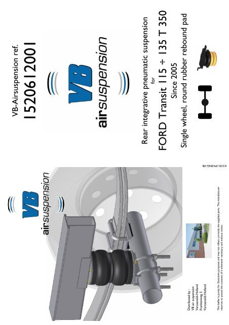
Distributed by :<br />
VB air suspension<br />
Varsseveld-Holland<br />
Frankenweg 3<br />
Varsseveld-Holland<br />
This leaflet is purely for illustrative purposes and may not reflect correctly the supplied parts. The manufacturer<br />
reserves to amend the contents of <strong>it</strong> whenever necessary and w<strong>it</strong>hout notice.<br />
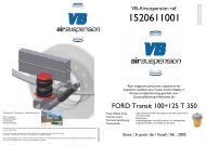
VB-Airsuspension ref.<br />
1520612001<br />
Rear integrative pneumatic suspension<br />
for<br />
<strong>FORD</strong> <strong>Trans<strong>it</strong></strong> <strong>115</strong> ÷ <strong>135</strong> T <strong>350</strong><br />
Since 2005<br />
Single wheel, round rubber rebound pad
VEHICLE INSTALLATION INSTRUCTIONS<br />
PACKAGE CONTENT<br />
Brake<br />
adjuster<br />
plate (1X)<br />
Nuts M6 (4X)<br />
Left and right air springs<br />
Clamps (4X)<br />
washers<br />
Ø6x16 (4X)<br />
SMALL ITEMS KIT<br />
Screws M6x25 (4X)<br />
Ghiera<br />
Staffetta di<br />
supporto<br />
Corpo valvola<br />
TOP DRIVE<br />
CONTROL<br />
Pressure stick (1X).<br />
Cappellotto<br />
di<br />
chiusura<br />
RILSAN PIPES KIT composed by:<br />
• Red pipe (6m);<br />
• Black pipe (6m).<br />
MANOMETERS KIT composed<br />
by:<br />
• Manometers w<strong>it</strong>h plastic<br />
ringnut (2x);<br />
• Inflating valves (2x);<br />
• Cups for manometers (2x).<br />
• Gauge support<br />
PRESSURE CONTROL KIT<br />
Composed by:<br />
• Body valves w<strong>it</strong>h pipe f<strong>it</strong>tings<br />
(2x);<br />
• Caps for pipe f<strong>it</strong>tings (6x);<br />
• Support plate (2x);<br />
• Ringnuts (2x).<br />
Clips KIT<br />
Composed by:<br />
• Plastic clips (20x).<br />
Installation instruction<br />
pneumatic<br />
system (1X).<br />
RIGHT SIDE<br />
RIGHT SIDE<br />
RIGHT SIDE<br />
Drive way<br />
1<br />
Drive way<br />
2<br />
3<br />
Place the vehicle in a hole or<br />
bridge, to operate in SAFE<br />
and confortably.<br />
Unscrew both, left and right rubber rebound<br />
pad and give them to the end user.<br />
RIGHT SIDE<br />
RIGHT SIDE<br />
RIGHT SIDE<br />
Insert this<br />
pin in the<br />
chassis hole<br />
4<br />
5<br />
6<br />
Place the suspension between axle and chassis, the upper and lower connecting systems respectively to<br />
the chassis and to the axle.<br />
Pin in the upper connecting system, must be insert in the hole visible after removing rebound pad.<br />
RIGHT SIDE RIGHT SIDE<br />
RIGHT SIDE<br />
7<br />
8<br />
9<br />
Fasten the lower connection system to the axle w<strong>it</strong>h clamps included in the package.<br />
LEFT SIDE<br />
LEFT SIDE<br />
LEFT LATO SIDE SX<br />
LEFT SIDE<br />
Drive way<br />
Rear brake<br />
adjuster<br />
Wheel side<br />
10<br />
11<br />
12<br />
13<br />
Left side: before f<strong>it</strong>ting left suspension, unmount brake regulator like pictures above, lift the support break regulator plate fixed at the chassis rotating <strong>it</strong> like pictures 12.<br />
Install left suspension following instructions showed in pictures 1 to 9 and mount brake regulator. Support brake regulator plate will be leaned at the upper connection<br />
system, just a l<strong>it</strong>tle lifted (see pict. 13).<br />
REAR BRAKE REGULATOR INSTRUCTIONS<br />
Differential gearbox<br />
Brake<br />
regulator<br />
bar<br />
Linking sistem of lower side, brake regulator bar<br />
Unscrew the support of brake regulator<br />
bar fixed at the differential gearbox.<br />
Place the 4 holes plate included in the package,<br />
between lower support and differential gearbox.<br />
Fasten <strong>it</strong> using two screw M6x25, washers and nuts.<br />
Fasten the four holes plate and the lower<br />
side of brake regulator bar w<strong>it</strong>h screws<br />
included in the package.<br />
Put the work pressure stick in a place visible for the driver, in the cabin.<br />
NOTE: for the execution of pneumatic system, follow specific instructions<br />
not included in this manual. See the “pneumatic system:<br />
installation instructions” form (see picture right).<br />
WARNING : For the execution of the pneumatic system, please strictly refer the specific given instructions. In fact , the system may vary<br />
according to the chosen version (manual, self levelling or electrical); so than the instructions for the pneumatic system are stated in the<br />
appos<strong>it</strong>e handbook enclosed at the purchased k<strong>it</strong>.<br />
IMPORTANT: do NOT use liquid Teflon®, hemp, paints etc. .In case of problem and/or information, contact our technical office. In case<br />
you fail to comply at this indications, society “VB air suspension” aren’t responsible for eventually damages derivates. For further information<br />
contact us.