Water Heater Manual - Pvi.com
Water Heater Manual - Pvi.com
Water Heater Manual - Pvi.com

You also want an ePaper? Increase the reach of your titles
YUMPU automatically turns print PDFs into web optimized ePapers that Google loves.
INSTALLATION & MAINTENANCE MANUAL FOR<br />
MAXIM<br />
INTEGRATED WATER HEATING SYSTEM<br />
IMPORTANT: READ AND FOLLOW THE INFORMATION IN THIS MANUAL, THE GENERAL<br />
INSTALLATION & MAINTENANCE MANUAL, AND ALL OTHER PROVIDED INSTRUCTIONS,<br />
LABELS AND MARKINGS BEFORE INSTALLING, OPERATING OR SERVICING THIS UNIT.<br />
TABLE OF CONTENTS<br />
Typical Construction 2<br />
Introduction 3<br />
Start-up Procedures & Warnings 4 – 5<br />
Electrical 5<br />
Maintenance & Safety Inspections 5 – 7<br />
MX Burner <strong>Manual</strong>, Start-up & Troubleshooting Guide 8 – 14<br />
MXG Burner <strong>Manual</strong><br />
Refer to PV500-21A<br />
MXO Burner <strong>Manual</strong><br />
Refer to PV500-22A<br />
MXL Burner <strong>Manual</strong><br />
Refer to Heat Wise SU-3<br />
WARNING: If the information on the appliance and in the supplied manual(s) is not followed<br />
exactly, a fire, explosion or exposure to hazardous materials may result causing<br />
property damage, personal injury or loss of life.<br />
<br />
<br />
<br />
<br />
<br />
FOR YOUR SAFETY<br />
Do not store or use gasoline or other flammable vapors and liquids in the vicinity of this or any<br />
other appliance.<br />
WHAT TO DO IF YOU SMELL GAS<br />
Do not try to light any appliance.<br />
Do not touch any electrical switch; do not use any phone in your building.<br />
Immediately call your gas supplier from a neighbor's phone. Follow the gas supplier's<br />
instructions.<br />
If you cannot reach your gas supplier, call the fire department.<br />
Installation and service must be performed by a qualified installer, service agency, or the gas<br />
supplier.<br />
This product contains, or may <strong>com</strong>e to contain, materials that have been identified as carcinogenic,<br />
or possibly carcinogenic, to humans. Before installing, servicing, or removing this product, read and<br />
follow the supplied instructions.<br />
PVI INDUSTRIES, LLC<br />
3209 Galvez Ave.<br />
Fort Worth, TX 76111<br />
(800) 433-5654<br />
www.pvi.<strong>com</strong><br />
PV500-17 07/13 1<br />
Section 17
MAXIM<br />
INTEGRATED WATER HEATING SYSTEM<br />
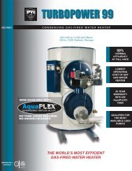
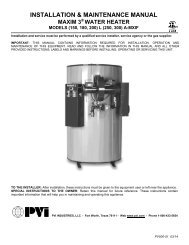
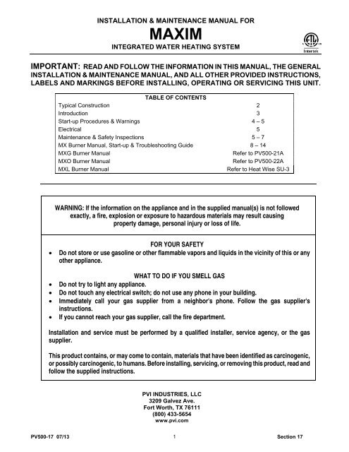
TYPICAL CONSTRUCTION - MX MODEL<br />
FIGURE 17-1<br />
1. VENT STACK * 8. HANDHOLE CLEANOUT<br />
2. TEMPERATURE LIMITING DEVICE (set at 200°F) 9. UPPER OPERATING THERMOSTAT (set at 130°F)<br />
3. OPERATING THERMOSTAT (set at 120°F) 10. COLD WATER INLET & RETURN CONNECTION<br />
4. CONTROL SWITCH(es) AND FUSE(s) 11. DRAIN<br />
5. GAS VALVE 12. RELIEF VALVE<br />
6. GAS INLET 13. PRIMARY SAFETY CONTROL<br />
7. BURNER (MX model shown) 14. DIFFERENTIAL AIR PROVING SWITCH<br />
WARNING! Temperatures higher than 125°F increase the risk of scald injury!<br />
(* NOT FURNISHED BY PVI)<br />
IMPORTANT! Clearance to unprotected <strong>com</strong>bustible material must be 8"min. at top, sides and rear, and<br />
24" min. in front.<br />
PV500-17 07/13 2<br />
Section 17
MAXIM<br />
PRODUCT SAFETY INFORMATION<br />
REFRACTORY CERAMIC FIBER PRODUCT<br />
WITH CRYSTALLINE SILICA<br />
WARNING: This product contains crystalline silica which has been identified by the International Agency<br />
for Research on Cancer (IARC) as carcinogenic to humans. This product also contains refractory ceramic<br />
fibers which have been identified by the IARC as possibly carcinogenic to humans.<br />
Avoid breathing fiber particulates and dust.<br />
RISKS:<br />
Airborne fibrous insulation is a possible cancer hazard by inhalation.<br />
Airborne crystalline silica may cause silicosis (lung disease) by inhalation.<br />
May cause temporary irritation to eyes, skin, and respiratory tract.<br />
PRECAUTIONARY MEASURES:<br />
Minimize airborne fibers with engineering controls.<br />
Use NIOSH/MSHA approved respirators as required (see MSDS).<br />
Wear long sleeved, loose-fitting clothing, eye protection, and gloves.<br />
FIRST AID MEASURES:<br />
Eyes: Flush with water.<br />
Skin: Wash with soap and warm water.<br />
Ingestion: Do not induce vomiting. Get medical attention if gastrointestinal symptoms develop.<br />
Inhalation: Remove to fresh clean air.<br />
If any of the above irritations persists, seek medical attention.<br />
WARNING! If you are unfamiliar with the safe handling of Refractory Ceramic Fiber<br />
products, or if you wish additional information prior to beginning any disassembly of the<br />
water heater that might expose refractory ceramic fiber materials, contact: Unifrax<br />
Corporation, 2351 Whirlpool Street, Niagara Falls, NY 14305-2413, 1-800-322-2293.<br />
INTRODUCTION<br />
This manual covers installation, operation and maintenance on all PVI <strong>com</strong>mercial water heaters and storage tanks. Read all<br />
instructions thoroughly before attempting to start any unit.<br />
CAUTION: Factory authorized start-up may be required on this equipment. Labeling on<br />
the unit will indicate this requirement.<br />
City, state and national codes governing installation of <strong>com</strong>mercial water heaters and storage tanks must<br />
be followed and take precedence over re<strong>com</strong>mendations in this manual.<br />
CODES FOR WATER HEATERS & BOILERS INSTALLATIONS<br />
ANSI Z223.1<br />
ANSI Z83.1<br />
NFPA No.31<br />
ANSI Z95.1<br />
NFPA No.54<br />
National Fuel Gas Code<br />
Installation of Gas Piping & Gas Equipment<br />
on Industrial & Certain other premises<br />
American Gas Association<br />
Installation of Oil Burning Equipment<br />
National Fire Protection Association<br />
Installation of Gas Appliances & Gas<br />
Piping<br />
CSA B149 Natural Gas & Propane Installation Code<br />
CSA B139 Installation Code for Oil Burning Equipment<br />
National Electrical Code National Fire Protection<br />
Association<br />
Canadian Electrical Code Part 1<br />
All Provincial Ordinances<br />
All State & Local Codes<br />
PV500-17 07/13 3<br />
Section 17
MAXIM<br />
START-UP PROCEDURES<br />
This water heater is equipped with an<br />
adjustable thermostat to control water<br />
temperature. Hot water temperatures<br />
required for automatic dishwasher and<br />
laundry use could cause scald burns<br />
resulting in serious personal injury and/or<br />
death. The temperature at which injury<br />
occurs varies with the person’s age and<br />
time of exposure. The slower response<br />
time of disabled persons increases the<br />
hazards to them. Never allow small<br />
children to use a hot water tap or to draw<br />
their own bath water. Never leave a child<br />
or disabled person unattended in a<br />
WARNING!<br />
bathtub or shower. Since the thermostat<br />
temperature setting could be set too high,<br />
adjust the thermostat temperature setting<br />
to 125°F or lower. Lower settings help<br />
reduce risk of scald injury. Remember, no<br />
water heater system will provide exact<br />
temperature at all times. Allow a few days<br />
of operation at this setting to determine<br />
the correct temperature setting consistent<br />
with your needs and remember, “Hotter<br />
water increases the risk of scald injury.”<br />
Also, the water heater should be located<br />
in an area where the general public does<br />
not have access to set temperatures.<br />
WARNING!<br />
Failure to follow these instructions can<br />
result in serious person injury or death.<br />
Do not relight pilot or start burner with<br />
<strong>com</strong>bustion chamber full of gas or oil<br />
vapor, or with very hot <strong>com</strong>bustion<br />
chamber.<br />
1. Study the burner start-up information included<br />
in this manual carefully.<br />
2. Fill the water heater tank with water. Open the<br />
relief valve or a nearby hot water faucet to<br />
allow air in the tank to escape.<br />
Be sure all connections into the tank are tight<br />
as leaks at tank fittings will damage the<br />
insulation.<br />
3. The top thermostat is a temperature limiting<br />
safety device set at 200°F. The thermostats<br />
are set at the factory at 130°F on the upper<br />
operating thermostat and 120°F on the lower<br />
operating thermostat. The lower operating<br />
thermostat should be set 10° lower than the<br />
upper operating thermostat setting. Adjustment<br />
may be made by turning the thermostat dial to<br />
the desired temperature.<br />
PV500-17 12-2004 4<br />
Section 17
MAXIM<br />
START-UP PROCEDURES (con't)<br />
CAUTION!<br />
Conduct the following gas train leakage test before start-up, at annual intervals and<br />
prior to investigating the cause of any reported occurrences of delayed ignition.<br />
1. Using an appropriate bubble detection<br />
solution, thoroughly coat all gas train pipe<br />
connections. If any bubbles are detected, the<br />
leaking connection must be tightened,<br />
recoated and rechecked to assure stoppage<br />
of the leak.<br />
2. Attach a manometer, to measure gas<br />
pressure, at the manual gas shutoff valve<br />
located just upstream of the gas train. Adjust<br />
gas train inlet pressure to the specified value<br />
(e.g. 14 in. W.C.), and tightly close the gas<br />
train manual shutoff valve closest to burner.<br />
3. Reattach the manometer to the gas train<br />
manual shutoff valve at the burner and record<br />
the measured gas pressure in inches of water<br />
column (in W.C.). Measure gas pressure<br />
again after 15 minutes. If gas pressure has<br />
increased 0.5" W.C. or more, the gas leak<br />
must be isolated to one or more of the<br />
operating gas valves, for example, a solenoid<br />
actuated gas shutoff valve. After any leaking<br />
valve is replaced, the reassembled gas train<br />
must be leak tested again before start-up is<br />
attempted. (NOTE: All gas valves removed<br />
because of suspected leakage must be<br />
returned to PVI Customer Service for<br />
disposition.)<br />
ELECTRICAL<br />
1. Wiring to the unit should conform to the<br />
National Electrical Code or the code legally<br />
authorized in your locality. A fused disconnect<br />
switch should be used for water heater<br />
control. Service wiring connections of 120V, 1<br />
phase, 60 Hz. are located in the enclosure on<br />
the water heater.<br />
IMPORTANT<br />
Use only copper wire of proper sizing for<br />
in<strong>com</strong>ing service. Damage resulting from<br />
use of aluminum wiring will be excluded<br />
from coverage under the warranty of this<br />
unit.<br />
MAINTENANCE AND SAFETY INSPECTIONS<br />
1. Establish a preventive maintenance program<br />
to assure a longer water heater life.<br />
2. The tank should be flushed at two- or threemonth<br />
intervals depending on water conditions<br />
in your location. To flush, turn off electrical<br />
disconnect switch to prevent the burner from<br />
operating. Open drain valve and allow water to<br />
flow through the tank until it runs clear. Close<br />
the drain valve and turn the electrical switch<br />
back on. Draining two or three gallons from the<br />
bottom of the tank on a weekly basis will also<br />
help prevent the accumulation of sediment.<br />
<strong>Water</strong> impurities consist of fine particles of soil<br />
or sand that will settle out and form a layer of<br />
sediment on the bottom of the tank.<br />
3. A scale of lime will normally form during<br />
operation and will accumulate on the bottom of<br />
the tank. Lime is formed from the natural<br />
chemicals in the water that precipitate out<br />
during heating cycles. Some water supplies<br />
contain more of these chemicals than others<br />
and scale buildup will occur more rapidly.<br />
Other factors affecting scale buildup are the<br />
amount of hot water used and temperature of<br />
the water. The more hot water used, the more<br />
fresh water containing scale-forming chemicals<br />
is brought into the tank. As the temperature of<br />
water increases, the rate of scale deposition<br />
will be increased.<br />
PV500-17 07/13 5<br />
Section 17
MAXIM<br />
MAINTENANCE AND SAFETY INSPECTIONS (con't)<br />
4. The tank will have a handhole for inspection<br />
and cleaning. (See Figure 17-1, page 2.) To<br />
inspect tank for scale buildup, remove the<br />
handhole cover. If scale is present, it can be<br />
loosened with a high pressure stream of water.<br />
The smaller pieces can be flushed through the<br />
drain and the larger pieces removed by hand<br />
through the handhole. The frequency of<br />
inspections will be determined by the rate of<br />
scale buildup. Intervals of 30-60 days are<br />
re<strong>com</strong>mended.<br />
IMPORTANT<br />
Condensate <strong>com</strong>ing from the tubes on a cold<br />
start is normal and does not indicate a leaking<br />
tube.<br />
6. Regularly inspect the bottom tubesheet.<br />
Inspect the SCALEGUARD tubesheet<br />
insulator for holes or areas that may have<br />
pulled away from tubesheet. Repair or replace<br />
as required.<br />
5. If a firetube leaks for any reason, consult<br />
factory for instructions.<br />
CARBON MONOXIDE WARNING!<br />
CAUTION: IMPROPER COMBUSTION MAY CAUSE SERIOUS INJURY.<br />
PVI re<strong>com</strong>mends a seasonal or annual <strong>com</strong>bustion check-out be performed by a<br />
qualified service agency to ensure safe and efficient operation.<br />
Periodic Inspection of Operational Components<br />
Periodic inspection and check-out of the burner ignition, control system, and fuel valve operation (for tight<br />
close-off) should be made. Refer to the burner installation instruction for re<strong>com</strong>mendations.<br />
1. Examine the venting system at least once each<br />
year for proper connections, alignment and<br />
corrosion. The blower inlet will collect dust from<br />
the air during operation. Disconnect the power to<br />
the heater and clean the blower wheel when<br />
necessary. Inspect all parts and make<br />
replacements when necessary. Check wiring for<br />
loose connections and burned wires.<br />
CAUTION!<br />
The relief valve is a primary safety device.<br />
2. The temperature and pressure relief valve may<br />
be checked by slowly lifting the seat lever on top<br />
of the valve to determine its condition for safe<br />
operation. The openings inside the valve may<br />
be<strong>com</strong>e restricted by a buildup of scale and<br />
be<strong>com</strong>e inoperative. If the valve does not open<br />
and close properly when tested, it must be<br />
replaced. Replace the relief valve with like kind or<br />
one meeting the requirements stated on the<br />
rating decal located adjacent to the relief valve.<br />
3. A table of periodic safety inspections is an<br />
attachment of this manual for ease of<br />
reference by the building service technician or<br />
licensed equipment operator. Since water<br />
heater designs vary, only some of these listed<br />
inspections may be appropriate for your<br />
particular model.<br />
4. PVI strongly re<strong>com</strong>mends the recording of<br />
significant events, such as maintenance or<br />
repair actions and safety inspections, and<br />
encourage the preparation of an event log for<br />
this purpose. All recorded events should be<br />
dated, fully described, and signed by the<br />
individual performing the service, repair, or<br />
inspection. (See Table 17-1, page 7 for<br />
sample of Inspection Record.)<br />
Call your PVI Customer Service Representative<br />
if you have any questions. (1-800-433-5654)<br />
PV500-17 07/13 6<br />
Section 17
MAXIM<br />
MAINTENANCE AND SAFETY INSPECTIONS (con’t)<br />
Instructions for Taking <strong>Water</strong> <strong>Heater</strong> Out of Service<br />
Extended shutdown of the appliance and<br />
restarting are as follows:<br />
A. Turn off all power and fuel supplies.<br />
B. Drain and flush tank as previously discussed.<br />
C. Tag power switch(es) that fuel is off and tank<br />
is empty.<br />
D. Refill tank with water and turn fuel and power<br />
switch(es) on to restart. Reset all controls and<br />
conduct start-up of the appliance as<br />
discussed in the previous pages.<br />
MAINTENANCE & SAFETY INSPECTION REPORT<br />
DATE<br />
BURNER<br />
INSPECTION<br />
COMBUSTION<br />
ANALYSIS<br />
TANK<br />
INSPECTION<br />
TANK FLUSH<br />
& CLEANOUT<br />
TANK FITTING<br />
INSPECTION<br />
VENT<br />
INSPECTION<br />
THERMOSTAT<br />
INSPECTION<br />
GAS TRAIN<br />
LEAK TEST<br />
Re<strong>com</strong>mended<br />
Inspection<br />
Intervals<br />
YEARLY 6 MONTHS 6 MONTHS 3 MONTHS 6 MONTHS YEARLY YEARLY YEARLY<br />
TABLE 17-1<br />
NOTE: Burner Inspection and Combustion Analysis should be done by a factory-authorized service person.<br />
PV500-17 07/13 7<br />
Section 17
MAXIM<br />
AXIAL FLOW GAS BURNER<br />
CARBON MONOXIDE WARNING!<br />
CAUTION: IMPROPER COMBUSTION MAY CAUSE SERIOUS INJURY.<br />
PVI re<strong>com</strong>mends a seasonal or annual <strong>com</strong>bustion check-out be performed by a<br />
qualified service agency to ensure safe and efficient operation.<br />
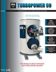
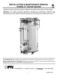
TYPICAL CONSTRUCTION<br />
MX MODEL APPLICATION<br />
FIGURE 17-2<br />
1. FAN HOUSING 9. AIR PROVING SWITCH<br />
2. AIR DAMPER 10. DAMPER ADJUSTMENT KNOB<br />
3. GAS NOZZLE ASSEMBLY 11. MANUAL SHUTOFF VALVE(s)<br />
4. PRESSURE PLATE 12. GAS PRESSURE REGULATOR<br />
5. BLAST TUBE & BURNER HOUSING JUNCTION 13. GAS VALVE<br />
6. IGNITION TRANSFORMER 14. AUXILIARY GAS VALVE<br />
7. IGNITION ELECTRODE 15. MAIN GAS TRAIN<br />
8. FLAME SENSING ROD 16. ELECTRODE CLAMP<br />
PV500-17 07/13 8<br />
Section 17
MAXIM<br />
AXIAL FLOW GAS BURNER START-UP<br />
(Refer to Figure 17-2, page 8 to identify burner parts)<br />
1. Remove the enclosure panel cover on the<br />
water heater or boiler to expose the control<br />
circuit. A wiring diagram, included in this<br />
packet, will show the controls used in our<br />
circuitry.<br />
2. Visually check that all <strong>com</strong>ponents are<br />
intact and no damage has occurred during<br />
transit.<br />
3. Check all connections within the control<br />
cabinet. A loose connection could cause<br />
intermittent shutdowns.<br />
4. Some burners will use direct spark ignition.<br />
They may use a single gas pressure<br />
regulator and gas valve or multiple valves<br />
and regulators. On a call for heat, the<br />
motor starts, the gas primary control is<br />
energized, and after a short delay (prepurge)<br />
the gas valve(s) opens and ignition<br />
should occur.<br />
IMPORTANT<br />
Do not tamper with or readjust program<br />
dipswitch settings. This will cause the<br />
control to be<strong>com</strong>e inoperable. Damage<br />
resulting from tampering will be<br />
excluded from coverage under the<br />
warranty of this unit.<br />
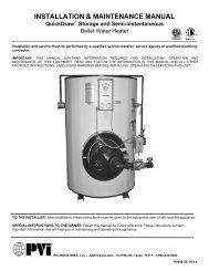
7. With the electrodes exposed, check them<br />
for the proper settings as called for in<br />
Figure 17-3, page 10. Check for any hairline<br />
cracks in the insulators. Should<br />
replacement of burner electrodes be<br />
required, certain procedures must be<br />
followed. In all cases, removal of the<br />
electrodes is ac<strong>com</strong>plished by loosening<br />
the electrode mounting clamps. Draw the<br />
electrodes out of the nozzle assembly<br />
through the holes in the pressure plate.<br />
8. Inspect the electrodes for cracked ceramic<br />
or loose retaining studs that hold the wire<br />
within the ceramic. Select the proper<br />
pressure plate hole to place each electrode<br />
and insert the electrode through the hole,<br />
retaining stud end first.<br />
9. Tighten electrode mounting clamp slightly<br />
until electrode ceramics are seated firmly<br />
and <strong>com</strong>pletely in the mounting bracket<br />
without gaps between ceramics and<br />
mounting bracket at the bearing faces.<br />
10. Measure and set electrodes according to<br />
Figure 17-3, page 10. After the gaps and<br />
setting are <strong>com</strong>plete, fully tighten the<br />
electrode mounting clamp. Do not<br />
overtighten or the insulation may crack.<br />
5. Remove the flame safeguard control from<br />
its base. Check the connections in control<br />
mounting base; loose connections can<br />
cause nuisance shutdowns. Check the<br />
time card or programmer, when applicable,<br />
for good connection.<br />
IMPORTANT<br />
Always secure gas lines and tag "Out of<br />
Service" before servicing burner nozzle<br />
or electrodes.<br />
6. Pull the nozzle assembly to check the<br />
flame and ignition electrodes. This is done<br />
by first disconnecting the gas train by<br />
breaking at the unions. Then removing the<br />
nozzle assembly which will have the<br />
electrodes and pressure plate attached.<br />
Disconnect the electrode wires and take<br />
care not to damage the insulation on the<br />
electrodes.<br />
11. Replace nozzle assembly; be sure to<br />
connect the flame and spark rod wires<br />
before installing nozzle assembly fully into<br />
blast tube. Check connectors on the ends of<br />
the flame and spark rod wires for good<br />
contact. Look for properly stripped wire<br />
ends. Be sure connectors are firmly<br />
attached to the flame and ignition rod ends.<br />
Insulating boots can give a false feeling of<br />
proper seating. DO NOT MOVE<br />
ELECTRODES. Be careful not to bump<br />
electrodes. Check fan wheel for free<br />
rotation.<br />
12. Reinstall orifices in unions (if required).<br />
Reinstall gas nozzle assembly.<br />
PV500-17 07/13 9<br />
Section 17
MAXIM<br />
AXIAL FLOW GAS BURNER START-UP (continued)<br />
PRESSURE PLATE<br />
13. Connect a test meter to the control for<br />
reading the flame response signal.<br />
IMPORTANT<br />
Some controls read the flame signal in<br />
micro amps and some in volts DC. The TFM<br />
or MEC120 series control has two terminals<br />
marked for reading volts DC. The S89<br />
control uses a micro amp signal for<br />
measuring flame strength. For this control, a<br />
meter must be hooked in series with the<br />
flame rod wire. Disconnect the leadwire at<br />
the S89 sensor terminal. Connect the<br />
positive lead of the meter to the quickconnect<br />
sensor terminal on the S89 and the<br />
negative lead to the free end of the sensor<br />
leadwire.<br />
Set up and Tolerances<br />
Figure 17-3<br />
Record static pressure; it must not exceed<br />
14" W.C. Pressures above this could cause<br />
damage to the diaphragm in the gas valve or<br />
pressure regulator.<br />
15. Burners with pilot; inputs over 400,000<br />
Btu/h (See wiring diagram.)<br />
16. Connect a manometer to the manifold test<br />
port at the shutoff valve closest to the<br />
burner. Turn off the main gas shutoff valve.<br />
Set the air shutter as shown on the tag<br />
attached to gas train. This may not be the<br />
exact setting you end up with, but it is a<br />
good starting point. Turn the unit on using<br />
the rocker switch on the side of the control<br />
enclosure assembly. If the operating control<br />
switches are closed, the burner blower<br />
should <strong>com</strong>e on and pre-purge begin.<br />
14. Be sure the tank is filled with water. Once<br />
the burner is reassembled, two devices will<br />
be needed to read gas pressures,<br />
If nothing happens, check the control to be<br />
preferably U-tube manometers. Connect<br />
sure it is not in the tripped position and<br />
one to read the inlet pressure of the burner.<br />
reset it by pushing the flame safeguard<br />
This is the pressure measured before all<br />
reset button. The burner should pre-purge<br />
<strong>com</strong>ponents in the gas train. The<br />
for no longer than thirty seconds.<br />
manometer must stay connected<br />
throughout the testing as the inlet pressure<br />
must be monitored during the firing of the<br />
burner.<br />
PV500-17 07/13 10<br />
Section 17
MAXIM<br />
AXIAL FLOW GAS BURNER START-UP (continued)<br />
This section pertains to MEC120 control only.<br />
When the blower motor starts, the air proving<br />
light on the MEC120 should be on. This<br />
indicates a positive airflow condition. If the air<br />
proving light is not on, turn air proving switch<br />
adjustment screw counter-clockwise until the<br />
air proving light <strong>com</strong>es on, then turn screw one<br />
turn counter-clockwise. If the gas valves open<br />
and close intermittently during normal<br />
operation, turn screw one half turn counterclockwise<br />
until this condition ceases. This<br />
procedure should be followed with every<br />
burner.<br />
After purging is <strong>com</strong>plete, terminal 3 energizes<br />
the pilot valve and terminal 4 energizes the<br />
ignition transformer on the control. The pilot is<br />
then established. The VDC reading on the<br />
meter should read a steady 14-17 VDC. Each<br />
different control will have the required flame<br />
response signal stamped on it. This is the<br />
minimum for it to properly operate. If the pilot<br />
fails to light during the initial period, it is<br />
probably due to air in the line. The control will<br />
lock out. Wait one minute and push the flame<br />
safeguard reset button to restart burner and<br />
begin the purge cycle again.<br />
Once the flame is established, set the pilot<br />
pressure (measured downstream of gas valve)<br />
at pressure shown on the tag attached to gas<br />
train. Next, open the main gas valve slowly.<br />
Set manifold pressure at pressure shown on<br />
the tag attached to gas train. Do not screw the<br />
adjusting nut of the regulator in past the point<br />
where no further increase in manifold pressure<br />
is noted. Check the in<strong>com</strong>ing pressure with the<br />
burner running. This is recorded as inlet flow<br />
pressure.<br />
Our standard flow pressure requirement on<br />
these burners is 8" W.C. flow. If the required<br />
manifold cannot be reached, check the inlet<br />
pressure. It should be a minimum of that<br />
shown on the heater decal with the burner<br />
running on full input. It is important that the<br />
in<strong>com</strong>ing pressure does not fall below these<br />
minimums or nuisance control lockouts could<br />
occur.<br />
IMPORTANT<br />
Where low gas pressure is a problem, special<br />
arrangements may have been made to fire the<br />
burner with reduced pressure. The appliance<br />
data decal will reflect this information.<br />
17. Direct Spark Ignition - (DSI) Burners - No<br />
pilot. (See wiring diagram.)<br />
Connect manometer to the manifold test port.<br />
Set the air shutter as shown on the tag<br />
attached to gas train. This may not be the<br />
exact setting you end up with, but it is a good<br />
starting point.<br />
Turn the unit on, using the rocker switch on the<br />
side of the control enclosure assembly. The<br />
burner should <strong>com</strong>e on and ignition occur. If<br />
the burner fails to ignite, there may have been<br />
air in the line. To reset the control, turn the<br />
switch off for 60 seconds (S89 controls only)<br />
and it should automatically reset, or push the<br />
reset button on the control. If after the<br />
appropriate prepurge, ignition does not occur,<br />
turn air proving switch adjustment screw<br />
counter-clockwise until TFI (try for ignition)<br />
occurs. Now in order to more precisely adjust<br />
the air failure set point, slowly turn screw<br />
clockwise until the burner shuts off. Then turn<br />
screw counter-clockwise one turn. If the gas<br />
valves open and close intermittently during<br />
normal operation, turn screw one half turn<br />
counter-clockwise until this condition ceases.<br />
Once the burner fires, set manifold pressure at<br />
pressure shown on the tag attached to gas<br />
train. There will be a tap on the downstream<br />
side of the valve to measure pressure. The<br />
manifold pressure must be taken downstream<br />
of the gas valve. Check the in<strong>com</strong>ing pressure<br />
with the burner running. This recorded flow<br />
pressure must be the minimum specified on<br />
the heater decal.<br />
PV500-17 07/13 11<br />
Section 17
MAXIM<br />
AXIAL FLOW GAS BURNER START-UP (continued)<br />
18. Check flue gases with a flue analyzer to<br />
make final settings of the air shutter.<br />
a. The readings need to be taken from a<br />
hole in the vent several inches above the<br />
heater vent connection, but before draft<br />
regulator.<br />
b. Insert draft gauge into the 1/4" test<br />
opening in the stack. Draft in stack should<br />
read -.02" to -.06" W.C. Adjust draft<br />
regulator, if installed.<br />
c. When water in the tank is above 120°F,<br />
insert analyzer or O 2 tester in 1/4" test<br />
opening and take O 2 reading in<br />
percentage.<br />
d. Gradually close air shutter, taking O 2<br />
reading at each adjustment of air shutter<br />
until optimum O 2 % (4-6%) is reached. If<br />
O 2 % decreases, open air shutter to last<br />
reading where the greatest reading is<br />
achieved.<br />
e. Insert CO tester in 1/4" test opening and<br />
take CO reading. CO should not exceed<br />
.03%. A reading greater than .03%<br />
indicates lack of air. Open air shutter<br />
slightly and take readings until CO is<br />
within proper range. Optimum reading is<br />
no CO.<br />
f. If air shutter was changed during CO test,<br />
take a final O 2 reading.<br />
g. Insert CO 2 tester in 1/4" test opening;<br />
record in percentage.<br />
h. Insert stack temperature gauge in 1/4"<br />
test opening and read gross stack<br />
temperature; maximum gross stack is to<br />
be 450°F, minimum net stack is to be<br />
300°F. (NOTE: net temperature is the<br />
total stack temperature, less room<br />
temperature.) If an excessively high<br />
gross stack temperature is recorded,<br />
check the flue tubes for turbulators.<br />
i. Make sure the air shutter is locked<br />
securely in place.<br />
19. On burners with pilots, recheck pilot to make<br />
sure its operation has not deteriorated if<br />
adjustments are made to the air shutter. To<br />
do this, shut off the main valve, check the<br />
flame response signal by cycling the burner<br />
through several lightoffs.<br />
20. Check each operating and limit control to be<br />
sure they function properly by lowering and<br />
raising the temperature setting on each<br />
control, causing the burner to cycle on and<br />
off.<br />
IMPORTANT<br />
During the initial firing of the burner, smoke<br />
that is not related to the burner will be<br />
emitted from the heater. This is normal during<br />
"burn in" and could possibly continue for<br />
several hours.<br />
21. Record the following information for future<br />
use:<br />
A. Air shutter position________________<br />
B. Manifold gas pressure________"W.C.<br />
C. Stack draft_________________"W.C.<br />
D. O 2 reading_______________%(4-6%)<br />
E. CO 2 reading______________%(8-9%)<br />
F. CO reading________%(less than .03%)<br />
G. Stack temperature:<br />
Gross _______________________°F.<br />
Less ambient__________________°F.<br />
Net__________________________°F.<br />
H. Combustion efficiency___________%<br />
PV500-17 07/13 12<br />
Section 17
MAXIM<br />
TROUBLESHOOTING SUGGESTIONS<br />
AXIAL FLOW GAS BURNER<br />
1. BURNER FAILS TO START<br />
Defective On/Off switch. Replace switch.<br />
A. Control circuit has an open control contact.<br />
Check limits, low water cutoff, proof of closure<br />
switch and others as applicable.<br />
B. Bad fuse or switch open on in<strong>com</strong>ing power<br />
source. Correct as required.<br />
C. Flame safeguard control safety switch<br />
tripped out. Reset and determine cause for<br />
apparent flame failure.<br />
D. Loose connections or faulty wiring. Tighten all<br />
terminals screws and consult wiring diagram<br />
furnished with the burner.<br />
E. Flame safeguard control starting circuit<br />
blocked due to flame relay being energized.<br />
Possible defective scanner or flame rod -<br />
replace. Possible defective amplifier - replace.<br />
Scanner actually sighting flame due to leaking<br />
fuel valve - correct unwanted flame cause.<br />
Defective flame safeguard control - replace.<br />
F. Defective blower motor. Check for free rotation<br />
of fan wheel. Repair or replace.<br />
G. Air proving switch is not properly adjusted.<br />
Adjust per instructions; page 11 of this manual.<br />
2. OCCASIONAL LOCKOUTS FOR NO APPARENT<br />
REASON<br />
A. Gas pilot ignition failure. Check to see that<br />
ignition is instant and that flame signal readings<br />
are stable and above minimum values. Use a<br />
manometer or 0 to 10" W.C. gas pressure gauge<br />
to make certain that pressure is as<br />
re<strong>com</strong>mended.<br />
B. Loose or broken wires. Check all wire nut<br />
connections and tighten all terminal screw<br />
connections in panel and elsewhere as<br />
appropriate.<br />
C. With flame safeguard controls that<br />
incorporate the air flow switch in the nonrecycling<br />
circuit, ensure that when main flame<br />
lights, the air flow switch is not so critically set as<br />
to allow occasional momentary opening of the air<br />
switch contacts.<br />
D. Occasional low voltage supply. Have local<br />
utility correct. Make certain the burner control<br />
circuit transformer (if supplied) is correct for the<br />
voltage and power (VAC) being supplied.<br />
E. Occasional low gas supply pressure. Have<br />
local utility correct.<br />
3. BURNER MOTOR RUNS, BUT PILOT DOES NOT<br />
LIGHT<br />
A. Gas supply to burner shut off. Make sure all<br />
manual gas supply valves are open. Automatic<br />
high pressure valve at meter such as "Sentry"<br />
type tripped shut due to high gas pressure.<br />
Reset valve and correct cause for trip out.<br />
B. Pilot solenoid valve not opening. Listen and<br />
feel for valve actuation. Solenoid valve not<br />
being powered. Check electrical circuitry.<br />
Replace coil or entire valve if coil is burned out.<br />
C. Defective gas pilot regulator. Replace.<br />
D. Gas pressure too high or too low at pilot<br />
orifice (if supplied). Check orifice size in gas<br />
pilot assembly. Replace if incorrect. Readjust<br />
pressure as required.<br />
E. Defective ignition transformer. Replace.<br />
Incorrect ignition electrode settings.<br />
Readjust as required.<br />
F. Defective flame safeguard control or plug in<br />
purge timing card. Replace as required.<br />
G. Air flow switch not making circuit. Check out<br />
electrically. Defective air flow switch- replace.<br />
Air switch negative pressure sensing tube out<br />
of position-reposition as necessary.<br />
4. BURNER MOTOR RUNS & PILOT LIGHTS, BUT<br />
MAIN GAS FLAME IS NOT ESTABLISHED.<br />
A. Main shut off or test cock closed. Check to<br />
make certain fully open.<br />
B. Pilot flame signal reading too low to pull in<br />
flame safeguard relay. Readjust as required.<br />
PV500-17 07/13 13<br />
Section 17
MAXIM<br />
TROUBLESHOOTING SUGGESTIONS<br />
AXIAL FLOW GAS BURNER (continued)<br />
C. Defective automatic main or auxiliary gas shut<br />
off valves. Check electrical circuitry to valves.<br />
Replace valves or correct circuitry as required.<br />
D. Main diaphragm shut off valve opening too<br />
slowly. Adjust bleed on valve.<br />
E. Defective flame safeguard control or plug on<br />
amplifier. Check and replace as required.<br />
F. Main gas pressure regulator atmospheric vent<br />
line obstructed. Correct.<br />
G. Defective main gas pressure regulator. Replace.<br />
Misadjusted main gas pressure regulator.<br />
Readjust to meet required operational values.<br />
H. Polarity reversed on in<strong>com</strong>ing power. (S89 control<br />
only)<br />
5. CARBON MONOXIDE READINGS ON GAS FIRING<br />
A. Flame impingement on "cold" heat transfer<br />
surfaces caused by excessive firing rate. Reduce<br />
firing rate to correct input volume.<br />
B. Incorrect gas/air ratios. Readjust burner to correct<br />
CO 2 /O 2 levels, eliminated all CO formation.<br />
6. GAS HIGH FIRE INPUT CANNOT BE ACHIEVED<br />
A. Gas <strong>com</strong>pany pressure regulator or meter<br />
operating incorrectly, not allowing required gas<br />
pressure at burner train inlet. Contact gas<br />
<strong>com</strong>pany to correct.<br />
B. Gas cock upstream of train inlet not fully open.<br />
Check and correct.<br />
C. Gas line obstructed. Check and correct.<br />
D. Gas train main and/or lead test cocks not fully<br />
open. Check and correct.<br />
E. Gas supply line between gas <strong>com</strong>pany<br />
regulator and burner inlet too small. Check<br />
supply pressure at meter, determine pressure drop<br />
and increase line size as required, or raise supply<br />
pressure to <strong>com</strong>pensate for small line. Do not raise<br />
pressure so high that under static (no flow)<br />
conditions the pressure exceeds the maximum<br />
allowable pressure to the gas train <strong>com</strong>ponents on<br />
the burner.<br />
F. Burner gas train <strong>com</strong>ponents sized too small<br />
for supply pressure. Increase <strong>com</strong>ponent size as<br />
appropriate or consult factory.<br />
G. Automatic gas valve not opening fully due to<br />
defective operation. Replace gas valve.<br />
H. Orifice (if supplied) too small. Replace with<br />
correct size.<br />
I. Defective main gas pressure regulator. Replace.<br />
J. Incorrect spring in main gas pressure regulator.<br />
Replace as required.<br />
K. Main gas pressure regulator vent line<br />
obstructed. Check and correct.<br />
L. Normally open vent valve (if supplied) not<br />
closing when automatic gas valves open. Check<br />
to see if valve is fully closed when automatic valves<br />
are open. Replace vent valve, if not closing fully.<br />
Additional troubleshooting information can be found in the Flame Safeguard bulletin supplied with the burner.<br />
PV500-17 07/13 14<br />
Section 17