installation & maintenance manual maxim 3 - Pvi.com
installation & maintenance manual maxim 3 - Pvi.com
installation & maintenance manual maxim 3 - Pvi.com

Create successful ePaper yourself
Turn your PDF publications into a flip-book with our unique Google optimized e-Paper software.
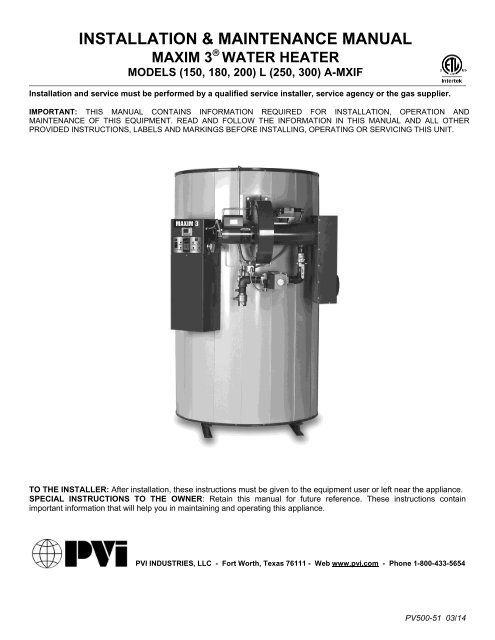
INSTALLATION & MAINTENANCE MANUAL<br />
MAXIM 3 WATER HEATER<br />
MODELS (150, 180, 200) L (250, 300) A-MXIF<br />
Installation and service must be performed by a qualified service installer, service agency or the gas supplier.<br />
IMPORTANT: THIS MANUAL CONTAINS INFORMATION REQUIRED FOR INSTALLATION, OPERATION AND<br />
MAINTENANCE OF THIS EQUIPMENT. READ AND FOLLOW THE INFORMATION IN THIS MANUAL AND ALL OTHER<br />
PROVIDED INSTRUCTIONS, LABELS AND MARKINGS BEFORE INSTALLING, OPERATING OR SERVICING THIS UNIT.<br />
TO THE INSTALLER: After <strong>installation</strong>, these instructions must be given to the equipment user or left near the appliance.<br />
SPECIAL INSTRUCTIONS TO THE OWNER: Retain this <strong>manual</strong> for future reference. These instructions contain<br />
important information that will help you in maintaining and operating this appliance.<br />
PVI INDUSTRIES, LLC - Fort Worth, Texas 76111 - Web www.pvi.<strong>com</strong> - Phone 1-800-433-5654<br />
PV500-51 03/14
MAXIM 3 ® WATER HEATER<br />
TABLE OF CONTENTS<br />
1. Safety Considerations<br />
2. Product Description<br />
3. Water Heater Installation<br />
3.1 Checking Equipment Before You Install<br />
4.2 Codes<br />
3.3 Electrical Requirements<br />
3.4 Handling and Location<br />
3.5 Service Clearances<br />
3.6 Clearances to Combustible Surfaces<br />
4. General Piping Guidelines<br />
4.1 Inlet and Outlet Connections<br />
4.2 Building Return Piping<br />
5. Gas Supply and Piping<br />
5.1 Gas Train and controls Certification<br />
5.2 Gas Control Trains<br />
5.3 Inlet Pressure<br />
5.4 Manifold Pressure<br />
5.5 Gas Piping Size<br />
5.6 Appliance Isolation during Gas Supply Piping Pressure Test<br />
5.7 Gas Connection<br />
6. Combustion and Ventilation Air<br />
6.1 Equipment Located in Confined Spaces<br />
6.2 Maximum Allowed Remote Combustion Air Inlet Length<br />
6.3 Remote Combustion Air Cap<br />
6.4 Vertical or Horizontal Remote Air Duct Termination<br />
6.5 Remote Air Consideration for Combined Remote Air Ducting<br />
7. Venting<br />
7.1 Venting the Unit Category I, III or IV Venting Materials<br />
7.2 Category I Venting<br />
7.3 Category III or Venting<br />
7.3.1 Maximum Category III or Category IV Vent Length<br />
7.3.2 Vertical or Horizontal Vent Termination<br />
7.3.3 Combining Category III or Category IV Vents<br />
8. Operating and Safety Controls<br />
8.1 Temperature and Pressure Relief Valve(s)<br />
8.2 Operating Temperature Control<br />
8.3 High Water Temperature Limit Control<br />
8.4 Cathodic Protection<br />
8.5 Electronic Low Water Cut-off (optional)<br />
2<br />
PV500-51 03/14
MAXIM 3 ® WATER HEATER<br />
9. TEMPTRAC Electronic Controller Panel<br />
9.1 Principal of Operation<br />
9.2 Upper LED Readout<br />
9.3 Lower LED Readout<br />
9.4 Control Buttons<br />
9.5 To View the Setpoint<br />
9.6 To Change the Setpoint<br />
9.7 To Change Other Parameters<br />
9.8 LED Display Alarm Messages<br />
10. Remote Connections – Terminal Strip<br />
10.1 Making BMS/BAS Remote Connection for Analog and Binary Signals<br />
10.2 Terminal Functions<br />
11. Sequence of Operation<br />
12. Initial Startup<br />
12.1 Initial Startup Requirements<br />
12.2 Tools and Instrumentation Required<br />
12.3 Resources<br />
12.4 On Site Considerations<br />
12.5 Startup Procedure<br />
13. Troubleshooting Guide<br />
14. Replacement Parts<br />
14.1 Control Panel<br />
14.2 Control Panel Components<br />
14.3 Burner Assembly<br />
14.4 Burner Assembly Components<br />
15. Periodic Maintenance<br />
16. Re<strong>com</strong>mended Maintenance Schedule<br />
Warranty forms ship separately with each product.<br />
3<br />
PV500-51 03/14
MAXIM 3 ® WATER HEATER<br />
1 SAFETY CONSIDERATIONS<br />
WARNING: If the information in the supplied <strong>manual</strong>(s) is not followed exactly, a fire, explosion or exposure to<br />
hazardous materials may result, causing property damage, personal injury or loss of life.<br />
FOR YOUR SAFETY<br />
Do not store or use gasoline or other flammable vapors or liquids in the vicinity of this or any other appliance.<br />
WHAT TO DO IF YOU SMELL GAS<br />
Do not try to light any appliance.<br />
Do not touch any electric switch; do not use any phone in your building.<br />
Immediately call your gas supplier from a location away from your building and the smell of gas. Follow the gas<br />
supplier's instructions.<br />
If you cannot reach your gas supplier, call the fire department.<br />
Installation and service must be performed by a qualified installer, service agency or the gas supplier.<br />
This product contains, or may <strong>com</strong>e to contain materials that have been identified as carcinogenic, or possibly carcinogenic<br />
to humans. Before installing, servicing or removing this product, read and follow the supplied instructions<br />
WARNING: Installation and service must be performed by a qualified installer, service agency or the gas supplier,<br />
who must read and follow the supplied instructions before installing, servicing or removing this appliance. Refer to<br />
the information contained in this <strong>manual</strong>. Improper <strong>installation</strong>, adjustment, alteration, service or <strong>maintenance</strong> can<br />
cause property damage, personal injury, exposure to hazardous materials or loss of life.<br />
WARNING: Do not use this appliance if any part has been under water. Immediately call a qualified service<br />
technician to inspect the unit and to replace any part of the control system, all gas controls and all other items<br />
affecting safe appliance operation and which has been under water.<br />
WARNING: In an emergency shut the main gas supply valve to the appliance from a location safely away from the<br />
emergency. Failure to follow these instructions can cause property damage, personal injury, and exposure to<br />
hazardous materials or loss of life.<br />
PRODUCT SAFETY INFORMATION<br />
REFRACTORY CERAMIC FIBER PRODUCT WITH CRYSTALLINE SILICA<br />
WARNING: This product contains or may <strong>com</strong>e to contain crystalline silica, which has been identified by the<br />
International Agency for Research on Cancer (IARC) as carcinogenic to humans. This product also contains<br />
refractory ceramic fibers, which have been identified by the IARC as possibly carcinogenic to humans. Avoid<br />
breathing fiber particulates and dust.<br />
RISKS:<br />
Air borne fibrous insulation is a possible cancer hazard by inhalation.<br />
Airborne crystalline silica may cause silicosis (lung disease) by inhalation.<br />
May cause temporary irritation to eyes, skin, and respiratory tract.<br />
PRECAUTIONARY MEASURES:<br />
Minimize airborne fibers with engineering controls.<br />
Use NIOSH/MSHA approved respirators as required (see MSDS).<br />
Wear long sleeved, loose-fitting clothing, eye protection and gloves.<br />
FIRST AID MEASURES: (If any of the irritations listed persists, seek medical attention)<br />
Eyes: Flush with water.<br />
Skin: Wash with soap and warm water.<br />
Ingestion: Do not induce vomiting. Get medical attention if gastrointestinal symptoms develop.<br />
Inhalation: Remove to fresh clean air.<br />
WARNING: If you are unfamiliar with the safe handling of refractory ceramic fiber products, or if you wish additional<br />
information prior to beginning any disassembly of the water heater or boiler that might expose refractory ceramic<br />
fiber materials, contact: Unifrax Corporation, 2351 Whirlpool Street, Niagara Falls, NY 14305-2413, 1-800-322-2293.<br />
IDENTIFICATION OF REFRACTORY CERAMIC FIBER MATERIALS (RCF):<br />
The burner, lower tank and upper and lower flue collector assemblies utilize RCF material. (The RFC materials are located<br />
within the product and not generally exposed except during service, disassembly or assembly.)<br />
4<br />
PV500-51 03/14
MAXIM 3 ® WATER HEATER<br />
IMPORTANT SAFETY NOTE<br />
It takes only 5 seconds of skin contact with 140°F water to cause a<br />
second degree burn! You must protect against high water temperatures at all<br />
lavatories, tubs, showers and other points of hot water contact.<br />
Accidental scalding from high water temperatures is a greater<br />
risk in some types of <strong>installation</strong>s. Some examples are:<br />
HOMES FOR THE MENTALLY HANDICAPPED<br />
HOMES FOR THE PHYSICALLY HANDICAPPED<br />
HOSPITALS AND NURSING HOMES<br />
ELDER CARE FACILITIES AND REST HOMES<br />
ORPHANAGES AND CHILD CARE FACILITIES<br />
OTHER INSTALLATIONS - WHERE RESPONSE TO CONTACT WITH HOT<br />
WATER MAY BE SLOWER OR WHERE THE DANGER OF HOT WATER<br />
CONTACT IS GREATER<br />
Thermostatically controlled mixing valves must be used in the<br />
design of the potable hot water system.<br />
Potable hot water should be tempered to no more than<br />
110°F when used for bathing or other personal uses.<br />
Good engineering practice mandates the use of thermostatically controlled<br />
mixing valves set at 120°F or less to keep the delivered water temperature<br />
below scalding temperatures.<br />
5<br />
PV500-51 03/14
MAXIM 3 ® WATER HEATER<br />
2 PRODUCT DESCRIPTION Component, Controls and Connection Locations<br />
(Locations May Vary)<br />
6<br />
PV500-51 03/14
MAXIM 3 ® WATER HEATER<br />
3 WATER HEATER INSTALLATION<br />
3.1 Checking Equipment Before You Install<br />
Inspect the unit <strong>com</strong>pletely upon receipt from the freight carrier before signing the bill of lading. Inspect the appliance<br />
and all ac<strong>com</strong>panying parts for signs of impact or mishandling. Verify the total number of pieces shown on packing<br />
slips with those actually received. Contact the freight carrier immediately if any damage or shortage is detected.<br />
3.2 Codes<br />
The equipment must be installed in accordance with those <strong>installation</strong> regulations in force in the local area where the<br />
<strong>installation</strong> is to be made. Authorities having jurisdiction must be consulted before <strong>installation</strong> is made. In the<br />
absence of such requirements, the <strong>installation</strong> shall be in accordance with the instructions in this <strong>manual</strong>, appliance<br />
markings and supplemental instructions and in <strong>com</strong>pliance with the latest edition of the National Fuel Gas Code,<br />
ANSI Z223.1. Where required by the Canadian authority having jurisdiction, the equipment must be installed in<br />
accordance with the latest edition of the Installation Code for Gas Burner Appliances and Equipment CAN/CSA<br />
B149.1 and/or B149.2 and applicable Provincial Regulations. All appliances conform to the latest edition of the<br />
ASME Boiler and Pressure Vessel Code, Section IV, Part HLW.<br />
3.3 Electrical Requirements<br />
See appliance rating decal for electrical service requirements. The appliance must be electrically supplied and<br />
grounded in accordance with the requirements of the authority having jurisdiction or in the absence of such<br />
requirements, with the latest edition of the National Electrical Code ANSI/NFPA No. 70. In Canada, the electrical<br />
service must conform to local electrical codes and/or CSA C22.1, Canadian Electrical Code, Part 1.<br />
<br />
<br />
<br />
All wiring between the unit and field installed devices must be made with type T copper wire.<br />
Line voltage wire exterior to the appliance must be enclosed in approved conduit or approved metal clad cable.<br />
To avoid serious damage, DO NOT energize the unit until the system and appliance is full of water.<br />
3.4 Handling and Location<br />
WARNING: Use industry standard safe rigging methods, such as including the use straps and spreader bars<br />
and lifting from the water heater base skid assembly, when attempting to lift or move this product. Failure to<br />
follow industry safe rigging methods could result in property damage, serious injury or death.<br />
1. Check the data decal on the appliance. Be sure the electrical, water, oil, or gas supply is adequate for the<br />
<strong>installation</strong>.<br />
2. Carefully remove all shipping supports and bracing.<br />
3. These units are suitable for indoor <strong>installation</strong> only.<br />
4. Locate the unit so that if water connections should leak, water damage will not occur. When such locations<br />
are unavoidable, install a suitable drain pan, and plumb pan to ensure adequate drainage in the event of a<br />
leak. Under no circumstances is the manufacturer responsible for water damage in connection with this unit,<br />
or any of its <strong>com</strong>ponents. The manufacturer’s warranty does not cover water damage.<br />
5. Protect associated electrical <strong>com</strong>ponents and electrical connections from water (dripping, spraying, rain,<br />
etc.) during appliance operation and service.<br />
6. Place the appliance on a level, non-<strong>com</strong>bustible floor. Concrete over wood is not considered non<strong>com</strong>bustible.<br />
7. Do not install on carpet or other <strong>com</strong>bustible floor coverings. If <strong>installation</strong> over a <strong>com</strong>bustible floor is required,<br />
follow these guidelines:<br />
Use a base of hollow clay tile or concrete blocks from 8" to 12" thick and extending 24" beyond the sides.<br />
Place the blocks in line so that the holes line up horizontally to provide a clear passage through the blocks.<br />
Install 1/2” fireproof millboard with a 20-gage sheet metal cover over the block base.<br />
Center the unit on the base. Also follow this procedure if electrical conduit runs through the floor, and<br />
beneath the appliance. A field-installed base must meet all local fire and safety code requirements.<br />
7<br />
PV500-51 03/14
MAXIM 3 ® WATER HEATER<br />
3.5 Service Clearances<br />
Allow sufficient space to provide adequate clearances on all sides for service and inspection. At least 24” above the<br />
water heater is required for filter replacement and burner/gas control service, 18” at left and right sides of the<br />
appliance. Optional equipment may increase the clearance requirements. Allow sufficient space for installing and<br />
servicing connections such as water, gas, vent, <strong>com</strong>bustion air, electrical, pump and other auxiliary equipment.<br />
3.6 Clearances To Combustible Surfaces<br />
Minimum 1” clearance must be provided from any vent surface to adjacent <strong>com</strong>bustible material. The minimum<br />
clearances to unprotected <strong>com</strong>bustible material are 24” be provided at the front, 8” be provided at the rear and 8” at<br />
top, left and right sides of the appliance.<br />
4 GENERAL PIPING GUIDELINES<br />
4.1 Inlet and Outlet Connections<br />
1. Use only non-ferrous water piping and fittings. Do not use galvanized pipe or fittings. Use of ferrous or<br />
galvanized pipe or fittings can cause rust to form.<br />
2. Install shut-off valves and unions on the inlet and outlet water piping for servicing. Use caution when<br />
threading pipe nipples into tank connections to prevent cross threading, or over-tightening. Always use a<br />
back-up wrench on tank nipples when tightening unions, valves, etc.<br />
3. Insulate hot water and return circulation lines. Insulate cold water supply lines if subject to freezing during<br />
shutdown periods. IMPORTANT: Do not use the plumbing connected to the appliance as a ground for<br />
welding or any other purpose.<br />
4. Pipe the drain valve to a suitable open drain.<br />
4.2 Building Return Piping<br />
To <strong>maxim</strong>ize water heater efficiency, connect the building return (≈ 5 gpm) to the inlet piping as shown below.<br />
WATER HEATER PIPING GUIDELINE<br />
Single Water Heater – One Hot Outlet Temperature<br />
8<br />
PV500-51 03/14
MAXIM 3 ® WATER HEATER<br />
WATER HEATER PIPING GUIDELINE<br />
One Water Heater – One Sidearm Storage Tank<br />
WATER HEATER PIPING GUIDELINE<br />
Two Water Heaters – Single Hot Outlet Temperature<br />
9<br />
PV500-51 03/14
MAXIM 3 ® WATER HEATER<br />
5 GAS SUPPLY AND PIPING<br />
Verify that the type of gas specified on rating plate is supplied to the unit. This unit is orificed for operation up to 2000<br />
feet altitude. Appliance Btuh output derates 4% per 1000 feet elevation above sea level. Consult Factory for<br />
<strong>installation</strong>s above 2000 feet elevation.<br />
5.1 Gas Train and Controls Certification<br />
NOTE: The gas train and controls assembly provided on this unit have been tested under the applicable American<br />
National Standard to <strong>com</strong>ply with safety and performance criteria such as proper ignition, <strong>com</strong>bustion and safety<br />
shutdown operation.<br />
5.2 Gas Control Train<br />
All models include gas control trains with the following <strong>com</strong>ponents: main <strong>manual</strong> shutoff valve, two safety shutoff<br />
valves, proportionator regulator and a final <strong>manual</strong> valve with the manifold pressure tap on the side of the valve.<br />
These <strong>com</strong>ponents may be separate or two or more may be <strong>com</strong>bined in a <strong>com</strong>mon housing.<br />
CAUTION: Do not adjust or remove any screws or bolts on gas train control <strong>com</strong>ponents which are sealed<br />
with a red or blue colored <strong>com</strong>pound. Doing so will void all approvals and warranties.<br />
5.3 Inlet Pressure<br />
Measure at the inlet pressure tap located at the main gas cock. The inlet pressure must remain within the minimum<br />
and <strong>maxim</strong>um values while the unit is at rest and while the unit is operating at <strong>maxim</strong>um firing rate.<br />
INLET PRESSURE NAT. GAS LP<br />
Maximum Static Pressure (Inches-Water Column) 14" 14"<br />
Minimum Flow Pressure (Inches-Water Column) 4.5" 11"<br />
5.4 Manifold Pressure<br />
Measure at the pressure tap located downstream side of the <strong>manual</strong> valve closest to the burner. The rated manifold<br />
pressure appears on the product data label located near the front of the appliance.<br />
5.5 Gas Piping Size<br />
Use the values in “Convert Fittings To Equivalent Straight Pipe” to add the equivalent straight pipe for each elbow or<br />
tee to obtain the total distance from the meter.<br />
CONVERT FITTINGS TO EQUIVALENT STRAIGHT PIPE<br />
Diameter Fitting (inches) ¾" 1" 1¼" 1½" 2" 3" 4" 5"<br />
Equivalent Length of Straight Pipe (feet) 2' 2' 3' 4' 5' 10' 14' 20'<br />
Use this corrected total distance from the meter for determining the suggested pipe size in the “Single Unit<br />
Installation Suggested Gas Pipe Size” table.<br />
SINGLE UNIT INSTALLATION SUGGESTED PIPE SIZE<br />
Maximum Capacity for Natural Gas*<br />
MBTU/HR Based on 0.5" W.C. Pressure Drop**<br />
1-1/4" 1-1/2" 2" 2½" 3" 4"<br />
25 860 1320 2475 3900 7000 -<br />
40 660 990 1900 3000 5300 -<br />
60 - 810 1520 2400 4300 -<br />
80 - 690 1300 2050 3700 -<br />
100 - 620 1150 1850 3250 6700<br />
125 - - 1020 1650 2950 6000<br />
150 - - 950 1500 2650 5500<br />
175 - - 850 1370 2450 5000<br />
Equivalent Feet<br />
From Meter<br />
200 - - 800 1280 2280 4600<br />
*Multiplier for Propane: 1.57<br />
**Multiplier for alternate pressure drops: 0.3" W.C. 0.77; 1.0" W.C. 1.41; 2.0" W.C. 2.00; and 4.0" W.C. 2.82.<br />
10<br />
PV500-51 03/14
MAXIM 3 ® WATER HEATER<br />
MULTIPLE UNIT INSTALLATIONS GAS PIPING SIZE CHART<br />
Maximum Capacity of Pipe in Thousands of BTU’s per hour for gas pressures of 14 Inches Water Column (0.5<br />
PSIG) or less and a pressure drop of 0.05 Inch Water Column (Based on NAT GAS, 1025BTU’s per Cubic<br />
Foot of Gas and 0.60 Specific Gravity).<br />
Nominal Iron<br />
Pipe Size,<br />
Inches<br />
Length of Pipe in Straight Feet<br />
10 20 30 40 50 60 70 80 90 100 125 150 175 200<br />
3/4 369 256 205 174 155 141 128 121 113 106 95 86 79 74<br />
1 697 477 384 328 292 267 246 256 210 200 179 164 49 138<br />
1 1/4 1400 974 789 677 595 543 502 472 441 410 369 333 308 287<br />
1 1/2 2150 1500 1210 1020 923 830 769 707 666 636 564 513 472 441<br />
2 4100 2820 2260 1950 1720 1560 1440 1330 1250 1180 1100 974 871 820<br />
2 1/2 6460 4460 3610 3100 2720 2460 2310 2100 2000 1900 1700 1540 1400 1300<br />
3 11200 7900 6400 5400 4870 4410 4000 3800 3540 3300 3000 2720 2500 2340<br />
4 23500 16100 13100 11100 10000 9000 8300 7690 7380 6870 6150 5640 5130 4720<br />
5.6 Appliance Isolation during Gas Supply Piping Pressure Test<br />
1. The appliance and its provided <strong>manual</strong> shutoff valve must be disconnected from the gas supply piping system<br />
during any pressure testing of that system at test pressures in excess of ½ PSI (3.5 kPa).<br />
2. The appliance must be isolated from the gas supply piping system by closing its individual <strong>manual</strong> shutoff valve<br />
during any pressure testing of the gas supply piping system at test pressures equal to or less than ½ PSI (3.5<br />
kPa).<br />
3. The appliance and its gas connection must be leak-tested before placing it in operation.<br />
5.7 Gas Connection<br />
1. Safe operation of unit requires adequate gas supply with the required static and dynamic (flow) pressures.<br />
Actual piping selection depends on many variables that must be carefully considered by the gas piping system<br />
designer.<br />
2. Do not select gas pipe sizes based only on the supplied tables. These tables are for use by the gas piping<br />
system designer as a reference in checking pipe size selections.<br />
3. Gas pipe size may be larger than heater connection.<br />
4. Installation of a union is suggested for ease of service.<br />
5. Install a <strong>manual</strong> main gas shutoff valve, outside of the appliance gas connection and before the appliance<br />
provided appliance <strong>manual</strong> shutoff gas valve, when Codes require.<br />
6. The gas system installer should clearly identify the emergency shut-off device.<br />
7. A sediment trap (drip leg) MUST be provided in the inlet of the gas connection to the unit.<br />
8. The code <strong>com</strong>pliant vent limiters are designed and must respond to pressure changes in the <strong>installation</strong><br />
environment, as opposed to outdoor pressure. For proper operation, do not connect to outdoor atmosphere.<br />
11<br />
PV500-51 03/14
MAXIM 3 ® WATER HEATER<br />
6 COMBUSTION AND VENTILATION AIR<br />
Provisions for adequate <strong>com</strong>bustion and ventilation air to the mechanical room must be in accordance with Section<br />
5.3 “Air for Combustion and Ventilation” of the latest edition of the National Fuel Gas Code, ANSI Z223.1 and/or<br />
CAN/CSA B149, Installation Codes or applicable provisions of the local building codes.<br />
6.1 Equipment Located In Confined Spaces<br />
Equipment located in confined spaces requires two openings installed within 12” (30.5 cm) from the top and<br />
bottom of the room to assure adequate <strong>com</strong>bustion air and proper ventilation. The total input of all gas utilization<br />
equipment installed in the room must be used to determine the required minimum air volume needed for<br />
<strong>com</strong>bustion, ventilation and dilution of flue gasses.<br />
All Air From Outdoors:<br />
Each opening requires a minimum free area of 1 square inch per 4000 Btu/hr input if directly <strong>com</strong>municating<br />
with the outdoors or <strong>com</strong>municating to the outdoors through vertical ducts.<br />
Each opening requires a minimum free area of 1 square inch per 2000 Btu/hr input if <strong>com</strong>municating with the<br />
outdoors through horizontal ducts.<br />
• All Air From Inside The Building:<br />
Each opening requires a minimum free area of 1 square inch per 1000 Btu/hr input, but not less than 100<br />
square inches (0.06 m 2) .<br />
• Combination Of Air From The Indoors And From The Outdoors:<br />
Refer to National Fuel Gas Code, ANSI Z223.1 and/or CAN/CSA B149, Installation Codes or applicable<br />
provisions of the local building codes.<br />
NOTE: This unit may be installed with a remote air intake system which uses a make-up air duct to draw <strong>com</strong>bustion<br />
air directly from outdoors.<br />
WARNING: Adequate clean <strong>com</strong>bustion air must be provided to the appliance. Under no circumstances<br />
should the appliance ever be under a negative pressure. Particular care should be taken when exhaust fans,<br />
<strong>com</strong>pressors, air handling units, etc. may rob air from the appliance. The <strong>com</strong>bustion air supply must be<br />
<strong>com</strong>pletely free of any chemical or fumes, which may be corrosive to the appliance. Some <strong>com</strong>mon chemical<br />
fumes to avoid are fluorocarbons and other halogenated <strong>com</strong>pounds, most <strong>com</strong>monly present as<br />
refrigerants or solvents, such as Freon, trichloroethylene, perchlorethylene, chlorine, etc. These chemicals,<br />
when in contact with the equipment or when burned, form acids which quickly attack the tubes, flue<br />
collector, stack and other appliance and auxiliary equipment. The result of inadequate clean <strong>com</strong>bustion air<br />
or negative pressure can be premature unwarranted product failure or unsafe operation producing carbon<br />
monoxide that could escape into the building. Exposure to carbon monoxide can lead to injury or death.<br />
6.2 Maximum Allowed Remote Combustion Air Inlet Length (Equivalent Length)<br />
A vertical or horizontal remote air inlet system can be connected to this appliance without modification. The<br />
<strong>maxim</strong>um length of field supplied single wall pipe, such as galvanized ventilation pipe, is shown in the chart below<br />
titled Maximum Air Inlet Duct Equivalent Length. Use metal tape or RTV sealant to seal each pipe joint.<br />
Maximum Air Inlet Duct Equivalent Length<br />
Duct Size 6” Duct 7” Duct 8” Duct 9” Duct<br />
Max Equivalent Length 100 feet 130 feet 250 feet 450 feet<br />
To determine the <strong>maxim</strong>um straight length of duct allowed, use the Duct Fitting Equivalent Length chart below to find<br />
the total equivalent length for all duct fittings in your <strong>com</strong>bustion air system. Then subtract this number of feet from<br />
the total equivalent length allowed in Maximum Air Inlet Duct Equivalent Length chart above. The sum of this<br />
calculation is the <strong>maxim</strong>um length of straight duct allowed. If a longer length is required, repeat the calculation using<br />
a larger duct size. No additional deduction is required for the addition of the duct system terminal.<br />
12<br />
PV500-51 03/14
MAXIM 3 ® WATER HEATER<br />
Duct Fitting Equivalent Length<br />
Duct Pipe: 6” Duct 7” Duct 8” Duct 9” Duct<br />
90º Elbow 8 feet 9 feet 10 feet 11 feet<br />
90º Long Radius Elbow 5 feet 5 feet 5 feet 6 feet<br />
45º Elbow 5 feet 5 feet 5 feet 5 feet<br />
The following remote air duct information is provided for use in design calculations, if needed.<br />
Remote Air Duct Specifications<br />
Input Mbtu Required Air (SCFM)<br />
1500 350<br />
1800 420<br />
2000 467<br />
6.3 Remote Combustion Air Cap<br />
A UL Listed air intake vent termination cap MUST be attached to the remote <strong>com</strong>bustion air vent termination to<br />
adequately protect the <strong>com</strong>bustion air inlet from wind and weather. A UL Listed air intake termination cap is available<br />
from PVI Industries and may have shipped with the water heater as a purchased option.<br />
6.4 Vertical or Horizontal Remote Air Duct Termination<br />
6.4.1 Air inlet and exhaust vents should terminate in the same wind pressure area whenever possible.<br />
6.4.2 Air inlet must be located no less than 3 feet (0.91m) below the exhaust terminal if they are within 10 feet<br />
(3.05 m) of each other.<br />
6.4.3 If terminating through the roof, the air inlet must terminate at least 12 inches (0.3 m) above roof level and<br />
at least 12 inches (0.3 m) above snow levels.<br />
6.4.4 If terminating through a sidewall, the air inlet must terminate at least 12 inches (0.3 m) above grade<br />
and/or at least 12 inches (0.3 m) above normal snow levels.<br />
Vertical Remote Air<br />
Horizontal Remote Air<br />
6.5 Remote Air Consideration for Combined Remote Air Ducting<br />
Each water heater MUST have separate intake piping. Consult factory for <strong>com</strong>mon air intake pipe sizing.<br />
13<br />
PV500-51 03/14
MAXIM 3 ® WATER HEATER<br />
7 VENTING<br />
7.1 Venting the unit using Category I, III or IV Venting Materials<br />
The following instructions can be used to install the VT3 using UL, ULC, ETL or CSA listed, Category I, negative<br />
pressure, non-condensing vent materials, like type B venting or it can be installed using smaller diameter UL, ULC,<br />
ETL or CSA listed, stainless steel, Category III, positive pressure, non-condensing venting materials. UL, ULC, ETL or<br />
CSA listed, stainless steel, Category IV, positive pressure, condensing ready venting materials can also be used to<br />
substitute for the Category III venting materials.<br />
Look at the main information decal attached near the front of the unit to determine whether the appliance is for<br />
<strong>installation</strong> utilizing Category I venting only, Category III venting only or if the appliance is for <strong>installation</strong> utilizing<br />
Category I, III or IV venting. Follow the instructions below for the specific Category of venting selected and that<br />
appears on the main information decal. Once the Category is selected, follow only the instructions given for that<br />
Category.<br />
WARNING: Venting instructions for Category I (negative vent pressure) and Category III/IV (positive vent<br />
pressure) must not be mixed. Mixing or following instructions for a different Category can cause inadequate<br />
venting or allow carbon monoxide to enter an occupied space, resulting in property damage, personal injury<br />
or death.<br />
7.2 CATEGORY I VENTING<br />
When properly installed with UL, ULC, ETL or CSA listed Category I venting, the appliance operates with a nonpositive<br />
vent static pressure and with a vent gas temperature that avoids excessive condensate production in the<br />
vent.<br />
Category I venting should terminate above the roof surface and must be installed in accordance with the "Venting of<br />
Equipment" section of the current edition of the National Fuel Gas Code, ANSI Z223.1 or, in Canada, the “Venting<br />
Systems and Air Supply for Appliances” section of the current edition of the CAN/CSA B149 Installation Codes, or<br />
applicable provisions of the local building codes.<br />
<br />
<br />
<br />
<br />
<br />
<br />
<br />
<br />
<br />
<br />
Do not use the flue outlet connection size to determine vent and vent connector size. For proper sizing use the<br />
National Fuel Gas Code “Fan-assisted” table.<br />
Locate units as close as possible to chimney. The vent connector from the appliance flue outlet connection to<br />
the vertical vent, stack or properly lined chimney, that terminates outside and above the building roof, must be<br />
made with listed Type “B” double wall (or equivalent), must be as direct as possible and must have no blockage<br />
or reduction in diameter.<br />
Support horizontal portions of the venting system to prevent sagging. Horizontal runs must slope upwards not<br />
less than 1/4 inch per foot (21 mm/m) from the appliance to the vent terminal. Follow manufacturer’s instructions.<br />
Do not attach the vent connector of any appliance vented by natural draft to any portion of a mechanical draft<br />
system operating under positive pressure.<br />
A barometric damper (draft control) is supplied for use on conventional vented <strong>installation</strong>s. A properly installed<br />
and adjusted barometric damper helps stabilize draft and regulate high updraft. Conventional vented multiple<br />
unit <strong>installation</strong>s with <strong>com</strong>bined venting require barometric dampers to regulate draft at each unit. Adjust the<br />
barometric damper to 0.04 inches water column updraft, when used. Follow the barometric damper<br />
manufacturer’s <strong>installation</strong> instructions.<br />
The draft in vent should be within a range of -.02 and -.08” W.C.<br />
A UL, ULC, ETL or CSA listed vent terminal, suitable for Category I products, must be installed to adequately<br />
protect the gas vent from wind and weather.<br />
The vent terminal must extend at least 3 ft (.09 m) above the highest point where it passes through the roof of a<br />
building and at least 2 ft (.06 m) higher than any portion of a building within a horizontal distance of 10 ft. (3.0 m).<br />
The vent cap must terminate at least 3 feet (0.91 m) above any forced air inlet within 10 feet (3.05 m); 4 feet<br />
(1.22 m) below, 4 feet (1.22 m) horizontally from or 1 foot (0.3 m) above any door, window or gravity air inlet to<br />
the building; 1 foot (0.3 m) above grade, 1 foot (0.3 m) above the highest snow levels and must terminate at least<br />
7 feet (2.13 m) above grade when located adjacent to public walkways or gathering areas.<br />
The vent terminal must not be installed closer than 3 feet (0.91 m) from an inside corner of an L-shaped<br />
structure.<br />
14<br />
PV500-51 03/14
MAXIM 3 ® WATER HEATER<br />
WARNING: Do not <strong>com</strong>bine appliances utilizing Category I or Category II venting into the same vent system<br />
with appliances utilizing Category III or Category IV venting. This could cause unsafe operation and the<br />
potential for poisonous carbon monoxide to enter occupied areas. Such improper <strong>installation</strong> can cause<br />
property damage, personal injury, exposure to hazardous materials or death.<br />
Conventional Venting<br />
Through the Wall Venting<br />
7.3 CATEGORY III or IV VENTING<br />
When properly installed with a UL, ULC, ETL or CSA listed, stainless steel, Category III or Category IV vent, the<br />
appliance operates with a positive vent static pressure and with a vent gas temperature that avoids excessive<br />
condensate production in the vent. Although the appliance can be installed to operate and require Category III vent<br />
materials, Category IV vent materials can be substituted, but are not required.<br />
The listed Category III or Category IV, stainless steel gas vent connected to this appliance may terminate either above<br />
the roof surface or through the side wall. It must <strong>com</strong>ply with the latest edition of the National Fuel Gas Code, ANSI<br />
Z223.1 or, in Canada, CAN/CSA B149 Installation Codes, and the applicable provisions of the local building codes.<br />
<br />
<br />
<br />
<br />
IMPORTANT: Do not use plastic venting of any type.<br />
Follow the Category III or Category IV vent manufacturers’ instruction for <strong>installation</strong>, sealing and support of their<br />
vent system.<br />
For proper vent operation and to protect the gas vent from wind and weather, use ONLY the listed vent terminal<br />
specified by the Category III or Category IV vent system manufacturer.<br />
IMPORTANT: Do not use a barometric damper when applying Category III or Category IV venting.<br />
This product uses the positive pressure generated by the burner system blower to push <strong>com</strong>bustion products out of<br />
the vent. The vent system must be a stainless steel and UL, ULC, ETL, or CSA certified for use with an appliance<br />
requiring a Category III or Category IV, pressurized vent system. Seal all joints and support horizontal lengths of<br />
vent and follow all <strong>installation</strong> instructions required by the vent manufacturer.<br />
WARNING: Use only stainless steel venting listed by a nationally recognized testing laboratory for Category III<br />
or Category IV, positive pressure, gas appliance venting. Use of plastic pipe of any type or use of venting<br />
material other than specified in these instructions can result in failure of the venting system and/or exposure<br />
to carbon monoxide, which can result in property damage, personal injury or death.<br />
WARNING: When using Category III or Category IV venting, do not connect this appliance to an existing or<br />
traditional gas vent or chimney or <strong>com</strong>bine the vent with any other appliance, except as provided in Section<br />
8.3.3 “Combining Category III or Category IV Vents.” Such venting could result in failure of the venting<br />
system and/or exposure to carbon monoxide which can result in property damage, personal injury or death.<br />
7.3.1 Maximum Category III or Category IV Vent Length (Equivalent Length)<br />
If a vertical or horizontal Category III or Category IV vent system is used with this appliance, the <strong>maxim</strong>um length<br />
of field supplied venting is shown in the chart below titled Maximum Category III – Category IV Vent Equivalent<br />
Length.<br />
15<br />
PV500-51 03/14
MAXIM 3 ® WATER HEATER<br />
Maximum Category III – Category IV Vent Equivalent Length<br />
Vent Size 6” Vent 7” Vent 8” Vent 9” Vent<br />
Max Equivalent Length 100 feet 130 feet 250 feet 450 feet<br />
Pipe fittings reduce the <strong>maxim</strong>um allowable vent length. Use the Category III or Category IV vent manufacturer’s<br />
equivalent length deduction for all elbows, terminations, etc. If the information is not readily available from the vent<br />
manufacturer, use the Vent Fitting Equivalent Length chart below to find the total equivalent length for all vent fittings<br />
in your <strong>com</strong>bustion air system. Then subtract this number of feet from the total equivalent length allowed in Maximum<br />
Category III – Category IV Vent Equivalent Length chart above. The sum of this calculation is the <strong>maxim</strong>um length of<br />
straight vent allowed. If a longer length is required, repeat the calculation using a larger vent size. When using this<br />
chart, no additional deduction is required for the addition of the vent system terminal.<br />
Vent Fitting Equivalent Length<br />
Vent Pipe: 6” Vent 7” Vent 8” Vent 9” Vent<br />
90º Elbow 8 feet 9 feet 10 feet 11 feet<br />
90º Long Radius Elbow 5 feet 5 feet 5 feet 6 feet<br />
45º Elbow 5 feet 5 feet 5 feet 5 feet<br />
The following vent information is provided for use in design calculations, if needed.<br />
Boiler<br />
Input Mbtu<br />
Venting Specifications<br />
Required<br />
Air (cfm)<br />
Max Vent<br />
Press. "W.C.<br />
1500 350 1.7<br />
1800 420 2.0<br />
2000 467 2.0<br />
7.3.2 Vertical or Horizontal Vent Termination<br />
1. The vent terminal must have a minimum clearance of 4 feet (1.22 m) horizontally from, and in no case be located<br />
above or below, electric meters, gas meters, regulators and relief equipment.<br />
2. The vent cap must terminate at least 3 feet (0.91 m) above any forced air inlet within 10 feet (3.05 m).<br />
3. The vent shall terminate at least 4 feet (1.22 m) below, 4 feet (1.22 m) horizontally from or 1 foot (0.3 m) above<br />
any door, window or building air inlet to the building.<br />
4. The vent system shall terminate at least 1 foot (0.3 m) above grade, at least 1 foot (0.3m) above highest possible<br />
snow accumulation levels and shall terminate at least 7 feet (2.13 m) above grade when located adjacent to<br />
public walkways or gathering areas.<br />
5. To avoid a blocked flue condition, keep the vent cap clear of snow, ice, leaves, debris, etc.<br />
6. The vent must not exit over a public walkway, near soffit vents or crawl space vents or other areas where<br />
condensate or vapor could create a nuisance or hazard or cause property or could be detrimental to the<br />
operation of regulators, relief valves or other equipment.<br />
7. A horizontal vent must extend one foot beyond the wall.<br />
8. A horizontal or vertical vent terminal must not be installed closer than 3 feet (0.91m) from an inside corner of an<br />
L-shaped structure.<br />
9. A vertical vent must exhaust outside the building at least 3 feet (0.91m) above the point of the exit and at least 2<br />
feet (0.61 m) above the highest point of the roof within a 10-foot (3.05 m) radius of the termination.<br />
10. A vertical termination less than 10 feet (0.91 m) from a parapet wall must be a minimum of 2 feet (0.61 m) higher<br />
than the parapet wall<br />
16<br />
PV500-51 03/14
MAXIM 3 ® WATER HEATER<br />
7.3.3 Combining Category III or Category IV Vents<br />
Combined VT3 Category III or Category IV gas vent systems must incorporate an Exhausto, Tjernlund or U.S.<br />
Draft variable speed, modulating, mechanical draft inducer capable of maintaining the appropriate negative draft<br />
at the end of the <strong>com</strong>mon flue, to assure that all boilers in the <strong>com</strong>bined vent system operate with a negative<br />
draft. Do not exceed negative 0.25” W.C. See “Combining Vents with a Draft Inducer” illustration below.<br />
WARNING: Do not connect multiple boiler vents into a single unpowered or fixed speed powered vent.<br />
This could cause unsafe operation and the potential for poisonous carbon monoxide to enter occupied<br />
areas. Such improper <strong>installation</strong> can cause property damage, personal injury, exposure to hazardous<br />
materials or death.<br />
WARNING: Do not <strong>com</strong>bine appliances utilizing Category I or Category II venting into the same vent<br />
system with appliances utilizing Category III or Category IV venting. This could cause unsafe operation<br />
and the potential for poisonous carbon monoxide to enter occupied areas. Such improper <strong>installation</strong><br />
can cause property damage, personal injury, exposure to hazardous materials or death.<br />
Conventional Venting Through the Wall Venting Combining Vents with a Draft Inducer<br />
8 OPERATING AND SAFETY CONTROLS<br />
WARNING: Turn off all electrical service to the appliance when accessing the limit or other controls located<br />
inside the control cabinet. This cabinet contains High Voltage wiring and terminals. If the electrical service is<br />
not turned off and these terminals are touched, a dangerous shock causing personal injury or loss of life<br />
could occur. Close and fasten the control cabinet cover before restoring electrical service to the appliance.<br />
8.3 Temperature and Pressure Relief Valve (s)<br />
A Temperature and Pressure Relief Valve(s) sized in accordance with the ASME Boiler and Pressure Vessel Code is<br />
installed in the tank.<br />
WARNING: Secure the relief valve pipe to a suitable floor drain such that very hot water does not openly<br />
splash during a significant relief valve discharge. If the relief valve pipe is not routed and secured to a<br />
suitable drain, hot water discharge can result in property damage, scalding and personal injury or loss of<br />
life.<br />
The drain pipe may not be smaller than the relief valve opening and must be secured to prevent it from lifting out<br />
of the drain under discharge pressure.<br />
<br />
<br />
<br />
CAUTION: Do not install a reducing coupling, valve or other restriction in the T&P relief valve(s)<br />
discharge line. The discharge line shall allow <strong>com</strong>plete drainage of the valve and line. Relief valves should be<br />
<strong>manual</strong>ly operated at least once a year.<br />
Thermal Expansion - A relief valve that periodically discharges may result from thermal expansion, if the water<br />
heater is installed in a system closed by <strong>com</strong>ponents, such as a backflow preventer or check valve in the cold<br />
water supply. These systems must be provided with means to control expansion. Contact a water heater or<br />
plumbing professional to resolve this situation.<br />
CAUTION: Do not plug the relief valve, as this will eliminate the critical water temperature and pressure<br />
protection it provides.<br />
17<br />
PV500-51 03/14
MAXIM 3 ® WATER HEATER<br />
8.4 Operating Temperature Control<br />
An adjustable digital operating control is located in the front control panel. The control is factory pre-set at<br />
approximately 120 º F. To adjust the setpoint to deliver the desired water temperature, press and release the Set 1 key<br />
on the face of the control. When setpoint adjustment is enabled, use the arrow keys to adjust the set point to the<br />
desired system temperature. See TempTrac Electronic Controller Panel in this <strong>manual</strong> for more information.<br />
8.5 High Water Temperature Limit Control<br />
Appliances are equipped with adjustable limit and high limit controls to control the <strong>maxim</strong>um discharge water<br />
temperature. These controls are located inside the control cabinet and are accessed by removing the bottom control<br />
panel cover. The high limit control is optionally available as the <strong>manual</strong> reset type and may be reset by pressing the<br />
limit reset button, accessible through the control panel cover. Pressing the reset on the High Limit Control will not<br />
cause the control to reset until the water temperature has dropped below the set point of the <strong>manual</strong> reset High Limit<br />
Control. The Lower Limit is of the auto reset type and can be dial adjusted to operate just above the set point of the<br />
main Operating Temperature Control.<br />
8.6 Cathodic Protection<br />
PVI water heaters do not utilize cathodic protection. However, in hot water systems utilizing cathodic protection,<br />
hydrogen gas can be produced when the hot water system has not been used for a long period of time (generally<br />
two weeks or more). Hydrogen gas is extremely flammable. To prevent the possibility of injury under these<br />
conditions, one of the hot water system faucets should be opened for several minutes before using any electrical<br />
device connected to the hot water system. If hydrogen is present, there will be an unusual sound such as air<br />
escaping through the pipe as the hot water begins to flow. Do not smoke, have open flames or turn electrical<br />
switches on or off near the faucet at the time it is open.<br />
8.7 Electronic Low Water Cut-Off (Optional)<br />
When the water level is above the electrode position in the tank, the reset pushbutton will energize the control (LED<br />
will be lit). The control remains energized until the water level recedes below the electrode position (LED will not be<br />
lit). Unless otherwise specified, there is a three-second time delay on decreasing level. Water level must be below<br />
tank probe location for full three seconds before control de-energizes.<br />
18<br />
PV500-51 03/14
MAXIM 3 ® WATER HEATER<br />
9 TEMPTRAC ELECTRONIC CONTROLLER PANEL<br />
9.1 Principle Of Operation<br />
The water heater operates to satisfy the setpoint of the TempTrac digital control whose sensor is located near the top<br />
of the water heater tank. Demand (flow) will typically create a drop in temperature, thus activating the water heater to<br />
add heat to the stored water. This setpoint is the desired water temperature to maintain.<br />
9.2 Lower Led Readout<br />
The default display of the lower readout (Probe 1) is the stored water temperature sensed near the top of the water<br />
heater tank. This is used to regulate the temperature of the water heater.<br />
9.3 Upper Led Readout<br />
The default display of this readout will display “nu”. This readout can display a temperature reading from a 2 nd probe.<br />
The 2 nd probe can be installed in a thermal well (this optional probe and thermal well, with heat conductive paste, is<br />
custom and must be ordered from your PVI representative or directly from PVI) to remotely monitor water<br />
temperatures, such as blended water temperature, downstream of a thermal mixing valve or a remote storage tank.<br />
Both Probe 1 and Probe 2 temperatures are available for monitoring through the optional MODBUS RTU interface.<br />
9.4 Control Buttons<br />
SET<br />
UP<br />
DOWN<br />
CLOCK<br />
EXT<br />
ON/OFF<br />
Displays and modifies the temperature set points.<br />
In programming mode, it selects a parameter or confirms an operation.<br />
Displays and modifies the energy saving (Night Time setback) settings.<br />
In programming mode, it browses the parameter codes or increases a displayed value.<br />
Displays the working hours of the load relays.<br />
In programming mode, it browses the parameter codes or decreases a displayed value.<br />
Changes lower display from the stored water temperature to current time and day.<br />
Changes upper display from Probe 2 temperature to Probe 3 temperature (when installed).<br />
Also displays the temperature difference of the stored water temperature minus Probe 2<br />
temperature. In programming mode it sets the 4-20mA output (password is required).<br />
Switches the control ON or OFF.<br />
(See TempTrac User Manual PV500-40 for full description)<br />
19<br />
PV500-51 03/14
MAXIM 3 ® WATER HEATER<br />
9.5 To View The Setpoint<br />
<br />
<br />
Push and release the SET key to see the set point value.<br />
To return to normal display, press SET + UP or wait 15 seconds without pressing any key.<br />
9.6 To Change The Setpoint<br />
Push the SET key. The upper display will show the “St1” parameter name, while the lower display will show its<br />
value.<br />
Use the UP or DOWN key to cycle through the parameter names.<br />
Push the SET key to modify a parameter value. The value starts flashing in the lower display.<br />
To change it push the UP or DOWN keys. Push the SET key again to confirm the value and pass to the setting<br />
of next set point.<br />
Repeat the operations described at points 3, 4, 5.<br />
To Exit: press SET + UP or wait 15 seconds without pressing any key.<br />
NOTE: Each point has a time out of 15 seconds. If any key is pushed within 15 seconds the controller exits the set<br />
points programming procedure.<br />
NOTE: The set value is stored even when the procedure is exited by waiting the time-out to expire.<br />
9.7 To Change Other Parameters<br />
<br />
<br />
<br />
<br />
<br />
<br />
Push the SET and DOWN arrow simultaneously for 3 seconds.<br />
Select the required parameter. The name of the parameter is on the upper display; its value is on the lower<br />
display.<br />
Press the SET key: the value of the parameter will start blinking.<br />
Use UP or DOWN to change the value.<br />
Press SET to store the new value and move to the following parameter.<br />
To Exit: Press SET + UP or wait 15s without pressing a key.<br />
20<br />
PV500-51 03/14
MAXIM 3 ® WATER HEATER<br />
9.8 LED Display Alarm Messages<br />
Alarm messages are displayed in the upper LED readout and alternate with the default display. An alarm LED ICON<br />
is also illuminated. (See TempTrac User Manual PV500-40 for full description.)<br />
ALARM<br />
MESSAGE<br />
“P1”<br />
“P2”<br />
“P3”<br />
“HA”<br />
CAUSE<br />
TP1 probe failure<br />
TP2 probe failure<br />
TP3 probe failure<br />
High temperature limit<br />
setpoint exceeded<br />
RESULTS OF ALARM CONDITION<br />
Tank temperature sensor is not<br />
connected or is reading incorrectly. Call<br />
for heat and burner modulation output<br />
signal will revert to low fire.<br />
Temperature sensor is not connected<br />
or is reading incorrectly.<br />
Temperature sensor is not connected<br />
or is reading incorrectly or flue gas<br />
temperature protection is disabled (if<br />
used).<br />
Buzzer sounds, operation continues<br />
“LA” Low temperature alarm Buzzer sounds, operation continues<br />
HP<br />
Digital input 3 is activated<br />
for one or more of the<br />
following:<br />
Flame failure or any control<br />
<strong>com</strong>ponent failure, if<br />
equipped with alarm on any<br />
failure option<br />
Unit de-energized after timer delay<br />
RECOMMENDED<br />
ACTION<br />
Check wiring and sensor<br />
Terminals 14 & 17<br />
Check wiring and sensor<br />
Terminals 15 & 17<br />
Check wiring and sensor<br />
Terminals 16 & 17<br />
Manual reset required<br />
Manually reset required<br />
LP Digital input 2 is activated Unit de-energized after timer delay Manually reset required<br />
Mn1<br />
Mn2<br />
Mn3<br />
“rtc”<br />
Maintenance alarm for<br />
output 1<br />
Maintenance alarm for<br />
output 2<br />
Maintenance alarm for<br />
output 3<br />
The real time clock has lost<br />
its setting<br />
Buzzer sounds, operation continues<br />
Buzzer sounds, operation continues<br />
Buzzer sounds, operation continues<br />
Energy saving function disabled<br />
Check wiring and sensor<br />
Check wiring and sensor<br />
Check wiring and sensor<br />
Reprogram clock<br />
10 REMOTE CONNECTIONS – TERMINAL STRIP<br />
10.1 Making BMS/BAS remote connections for analog and binary (on/off) signals<br />
A terminal strip for the remote connection is located behind the hinged control panel at the top of the cabinet and is<br />
accessed by removing the bottom cover and then removing the screws at the top of the hinged cover.<br />
Important: Do not use single strand bell wire for remote field connections to terminals R1-R2 and C1-C2. Use only<br />
multi-strand copper wire. See table below for wire length and gauge:<br />
Wire Gauge 18 GA 16GA 14 GA 12 GA<br />
Maximum Length 30 FT 50 FT 75 FT 100 FT<br />
WARNING: Turn off all electrical service to the appliance when accessing the remote connections located<br />
inside the control cabinet. These terminals are High Voltage. If the electrical service is not turned off and<br />
these terminals are touched, a dangerous shock causing personal injury or loss of life could occur. Close<br />
and fasten the control cabinet cover before restoring electrical service to the appliance.<br />
21<br />
PV500-51 03/14
MAXIM 3 ® WATER HEATER<br />
10.2 The Following Describes The Functions Of Each Of These Terminals And The Factory-Installed Options<br />
Required To Activate The Terminals:<br />
Note: Terminals P1-P2 are functional only when the water heater is equipped with the factory installed options<br />
required to activate the terminals. Terminals R1-R2, A1-A2, C1-C2 and T1-T2 are standard pre-wired functions on<br />
all models.<br />
R1-R2: Used to activate /de-activate water heater from remote master control.<br />
Terminals are wired to a relay in a remote Energy Management System. When relay closes, circuit from R1 to R2 is<br />
<strong>com</strong>pleted and appliance controls are enabled. Appliance ships from factory with jumper between terminals<br />
Remove jumper when connecting to a remote controller.<br />
A1-A2: Used to activate a remote alarm, signaling shutdown of <strong>com</strong>bustion control.<br />
Provides a <strong>maxim</strong>um 10 amp relay contact closure when the flame safeguard terminates <strong>com</strong>bustion due to a<br />
tripped safety interlock (i.e.: air proving switch, high limit switch, low water flow switch or flame sensor, etc.).<br />
P1-P2: Activates remote equipment and requires confirmation signal back to the appliance.<br />
Provides a <strong>maxim</strong>um 10-amp relay contact closure to activate a remote device (i.e.: mechanical room air louvers,<br />
draft inducer or power vent, etc.). The remote device must send return signal via proving switch to confirming proper<br />
operation to terminals C1-C2, prior to the appliance being able to energize. Options Required - Consult Factory.<br />
C1-C2: Used for proving operation of remote device.<br />
Terminals are wired to a proving switch on a remote device such as a power venter. When relay closes, circuit from<br />
C1 to C2 is <strong>com</strong>pleted and appliance controls are enabled. This appliance ships form the factory with jumper<br />
between terminals.<br />
T1-T2: Used for external modulation control.<br />
To connect external modulation control, disconnect and cap the blue wire connected to terminal T2 and connect the<br />
external modulating signal to terminals T1 (positive) and T2 (negative).<br />
11 SEQUENCE OF OPERATION<br />
1. In<strong>com</strong>ing 120VAC<br />
a. Full time power to the Main Control Switch<br />
b. Full time power to the Variable Frequency Drive<br />
2. Power On - When the main control switch is turned on:<br />
a. 120v is applied to the step-down transformer (24v)<br />
b. 120v is applied to the L.W.C.O. terminal L1 (if used)<br />
c. 120v is applied to the Fenwal Flame Safeguard Control<br />
d. 24v is applied to the TempTrac operating temperature control terminal L1<br />
3. Call For Heat - If the TempTrac operating control senses a call-for-heat condition:<br />
a. The High Gas Pressure and Low Gas Pressure Switch (both optional) are energized and their safe<br />
condition is proved.<br />
b. The thermostat contact on the Fenwal Flame Safeguard Control is energized.<br />
c. The flame control will then verify the Airflow-Proving Switch is in the open position, which must exist before<br />
the blower is powered.<br />
d. Energizing the blower should close the airflow proving switch. If the airflow-proving switch is not in the<br />
closed position, the flame control’s fan terminals F1-F2 will power the Variable Frequency Drive (VFD)<br />
blower system at low speed for pre-purge.<br />
e. If the airflow-proving switch does not close following the blower being energized, the flame control will<br />
lockout.<br />
22<br />
PV500-51 03/14
MAXIM 3 ® WATER HEATER<br />
4. Proof of Air Pressure Switch - The control will look for a signal from the airflow-proving switch, indicating that<br />
the blower is operating:<br />
a. When the airflow generated by the blower is sufficient to cause the differential air switch to close, the 15 -<br />
second pre-purge delay will start.<br />
b. During this period any flue products or <strong>com</strong>bustible gases which may have settled in the water heater are<br />
evacuated.<br />
5. Heat-Up - Following the pre-purge delay, the hot surface igniter will be energized:<br />
a. The flame control will monitor the current applied to the hot surface igniter.<br />
b. If the flame control determines the proving current meets the threshold, a dwell time delay starts to assure<br />
the hot surface igniter has sufficient time to reach ignition temperature.<br />
6. Ignition - When dwell time is <strong>com</strong>pleted a 4-second Trial for Ignition (TFI) period is initiated:<br />
a. The Delay-On (Low Fire Hold) Relay and the Gas Safety Valves are energized.<br />
b. During TFI the flame safeguard control will monitor the flame using flame rectification through the hot<br />
surface igniter.<br />
c. If the flame control senses the presence of flame before the end of the TFI period, the igniter will be deenergized<br />
and the flame control will continue to monitor the flame, through the igniter, until the operating<br />
thermostat ends the call for heat condition.<br />
7. Loss of Flame Signal<br />
a. If the igniter fails to sense flame at any time, the igniter and gas valve will be de-energized and the flame<br />
control will reset and begin the call-for-heat sequence again. This will occur 3 times (one time if CSD-1)<br />
before the flame control will lockout.<br />
b. When the call for heat condition ends or flame failure occurs following the third TFI period (one time if CSD-<br />
1), a 30-second post-purge period will begin. This period of blower operation will exhaust any remaining<br />
<strong>com</strong>bustion products from the system.<br />
8. Delay-On Relay - Once the Delay-On (Low Fire Hold) Relay has timed out, it energizes the Modulation Release<br />
Relay (SPDT) to enable the analog signal from the TempTrac to the VFD to regulate the speed of the blower.<br />
a. The TempTrac will continue to monitor the stored water temperature in the tank.<br />
b. When the setpoint temperature is reached the call-for-heat signal to the flame safeguard control is<br />
discontinued.<br />
c. The flame safeguard control deenergizes the VFD blower system and the gas valve, thereby suspending<br />
burner operation.<br />
d. As heat is transferred to the building, the water heater loop temperature will fall below the set point. The<br />
TempTrac will sense this condition and begin the call-for-heat sequence again.<br />
9. Flame Safeguard LED Diagnostic Indicator - If the Fenwal Flame Safeguard Control at any time during the<br />
operating sequence senses an improper operating state and locks out, the diagnostic red LED located on the<br />
control board will flash to indicate one of the following conditions exist:<br />
LED INDICATION<br />
FAULT MODE<br />
On<br />
Normal Operation<br />
OFF<br />
Internal Control Failure – check power<br />
1 Flash Airflow Fault<br />
2 Flashes Erroneous Flame Signal<br />
3 Flashes Ignition Lockout<br />
4 Flashes Hot Surface Igniter Fault<br />
5 Flashes Low Voltage (24 VAC)<br />
6 Flashes Valve Relay Problem<br />
23<br />
PV500-51 03/14
MAXIM 3 ® WATER HEATER<br />
12 INITIAL STARTUP<br />
12.1 Initial Startup Requirements<br />
Installation should be <strong>com</strong>plete prior to performing initial startup; and the startup must be <strong>com</strong>plete prior to placing<br />
the water heater into service. Starting the water heater without proper piping, <strong>com</strong>bustion air, venting or electrical<br />
systems can be dangerous and may void the product warranty. The following startup instructions should be followed<br />
precisely in order to achieve safe and efficient operation to assure trouble-free service life.<br />
WARNING: Proper startup must be made by a qualified installer or service agency, who must read and<br />
follow the supplied instructions and appliance markings. Failure to <strong>com</strong>plete proper startup before use,<br />
tampering with controls or not following all instructions and markings may damage this equipment, void<br />
the warranty and may result in property damage, personal injury or death.<br />
A Start-up Form is included with each product and must be <strong>com</strong>pleted by the qualified installer or service agency<br />
conducting the startup and must be returned to the manufacture to register the warranty. Copies are available at<br />
www.pvi.<strong>com</strong>.<br />
WARNING: Turn off all power to the water heater when servicing or accessing the blower drive. The blower<br />
drive still has power when appliance switch is off. Failure to turn off all power to the water heater can cause<br />
personal injury, property damage or loss of life.<br />
12.2 Tools and Instrumentation Required<br />
<br />
<br />
<br />
<br />
<br />
<br />
<br />
Stack Temperature Gauge<br />
Stack Draft Gauge<br />
Electronic Combustion Analyzer<br />
Manometer for checking gas pressure (2 minimum)<br />
AC/DC Multi-meter (with 20,000 OHM/Volt rating)<br />
Amp Meter<br />
Normal Hand Tools<br />
12.3 Resources<br />
Product Installation & Maintenance Manuals<br />
Start-up Report with instructions<br />
Local, State, & Federal Codes<br />
Toll Free 24-Hour Technical Support: 1-800-433-5654<br />
12.4 On Site Considerations<br />
<br />
<br />
<br />
<br />
<br />
Electrical Supply in accordance with Nameplate Rating<br />
Uncontaminated Combustion Air<br />
Adequate Fuel Supply<br />
Treated Water Supply (Water heaters)<br />
Consistent Draft<br />
12.5 Startup Procedure<br />
1. Carefully study the burner start-up information included in this <strong>manual</strong>.<br />
2. Fill system tank with water. Some water appliances may be equipped with an optional air vent. If venting<br />
through the safety valve when filling the appliance, insure gags or fixtures are removed from the safety valve<br />
prior to start-up. Open the safety valve to allow air in the tank to escape.<br />
3. Be sure all connections into the tank are tight, as leaks at tank fittings will damage the insulation.<br />
4. CAUTION: Conduct the following gas train leakage test before start-up, at annual intervals and prior<br />
to investigating the cause of any reported occurrences of delayed ignition.<br />
a. Using an appropriate bubble detection solution, thoroughly coat all gas train pipe connections. If any<br />
bubbles are detected, the leaking connection must be tightened, recoated, and rechecked to assure<br />
stoppage of the leak.<br />
24<br />
PV500-51 03/14
MAXIM 3 ® WATER HEATER<br />
b. Attach a manometer to measure the gas pressure at the <strong>manual</strong> gas shutoff valve located just upstream<br />
of the gas train. Adjust gas train inlet pressure to the specified value (e.g. 14" W.C.), and tightly close the<br />
gas train <strong>manual</strong> shutoff valve closest to the burner.<br />
c. Reattach the manometer to the gas train <strong>manual</strong> shutoff valve at the burner and record the measured<br />
gas pressure in inches of water column (W.C.). Measure gas pressure again after 15 minutes. If gas<br />
pressure has increased 0.5" W.C. or more, the gas leak must be isolated to one or more of the operating<br />
gas valves. (For example, a solenoid actuated gas shutoff valve.) After any leaking valve is replaced, the<br />
reassembled gas train must be leak tested again before start-up is attempted.<br />
5. Remove enclosure panel cover on the appliance to expose control circuit. A wiring diagram, included in this<br />
packet, will show the controls used in our circuitry.<br />
6. Visually check that all <strong>com</strong>ponents are intact and no damage has occurred during transit.<br />
7. Check all connections within the control cabinet. A loose connection could cause intermittent shutdowns.<br />
8. All burners will use a hot surface igniter (HSI) as the ignition source. They may use a single gas pressure<br />
regulator and valves, valve regulator <strong>com</strong>binations or multiple gas trains.<br />
9. Connect a test meter to the control for reading the flame response signal.<br />
NOTE: Some flame controls read the flame signal in micro amps and some in volts DC.<br />
10. CAUTION: Be sure the tank is filled with water. Dry firing can destroy the appliance.<br />
11. Check the inlet gas pressure before start-up, using a manometer or a 0 to 28" W.C. pressure gauge for inlet<br />
gas pressure. (This is the pressure measured before all <strong>com</strong>ponents in the gas train.) This manometer must<br />
stay connected throughout the testing, as the inlet pressure must be monitored during the firing of the burner.<br />
Record static pressure; it must not exceed 14" W.C. Pressures above this could cause damage to the<br />
diaphragm in the gas valve or pressure regulator.<br />
12. Connect a second manometer to the manifold test port at the shutoff valve closest to the burner.<br />
13. Turn-off main gas shutoff valve.<br />
14. Disable or jumper out any BMS/BAS control interface to allow independent setup and adjustment of<br />
each water heater.<br />
15. Turn unit on using the rocker switch on the front of the control enclosure assembly. When the burner fails to<br />
light, the flame control will lockout.<br />
Start the burner in Low Fire (Burner <strong>com</strong>bustion must be optimized at both Low and High Fire). To set the<br />
TempTrac control for <strong>manual</strong> modulation output:<br />
Push and hold the EXT key for more than 3 seconds. The LED switches ON and the PS4 parameter<br />
is displayed in the upper display, while the PAS label is shown in the lower display.<br />
<br />
Release the key, and insert the password: 3-2-1. The value of the modulation parameter PS4 will be<br />
displayed in the lower display. (nu) stands for not used. Return to this condition for automatic operation.<br />
To adjust modulation <strong>manual</strong>ly, push the SET key, the value starts flashing. Then use UP or DOWN keys<br />
to modify it. 100 = High Fire; 0 = Low Fire.<br />
To exit, press SET + UP or wait 30s without pressing any key.<br />
NOTE: After a modification, it will be possible to enter the Modulation output setting without entering the<br />
password for 10min. After this time you will be asked for the password again.<br />
16. Turn-on main gas shutoff valve.<br />
17. If the operating control switches are closed, the burner blower should <strong>com</strong>e on and pre-purge begins.<br />
18. If nothing happens, check for a lockout condition and reset it by pushing the flame safeguard reset button.<br />
Some safety devices are wired in the operating circuit and may not indicate alarm. If no indication of alarm<br />
exists, check gas pressure switches, electronic low water cutoffs (if equipped) and temperature limits.<br />
25<br />
PV500-51 03/14
MAXIM 3 ® WATER HEATER<br />
19. When the blower motor starts, the flame control will check for a positive air flow. If the air switch or blocked<br />
filter switch is not made the blower will stay on for a period of time then lockout. To adjust the air-proving<br />
switch, turn the adjustment screw counter-clockwise until the air proving light <strong>com</strong>es on, then turn the screw<br />
one turn counter-clockwise. The blocked filter switch should only be adjusted when the filter is new. This<br />
switch should be turned clockwise until switch makes and then two additional turns. If the gas valves open<br />
and close intermittently during normal operation, adjust pressure switches to increase the operational<br />
threshold until this condition ceases. This procedure should be followed with every burner.<br />
20. After the pre-purge, the flame control energizes the HSI for the heat up period, approximately 30 seconds. At<br />
the end of that period the gas valve is opened for approximately 4 seconds. After the burner has lit and the<br />
primary safety control senses a flame, the burner will remain on until the call for heat is satisfied or operation<br />
is interrupted by a safety device.<br />
21. If the burner fails to light, the flame control will lockout. When this happens press the reset button on the front<br />
of the control to recycle burner and check for improper <strong>com</strong>bustion or week flame signal as a possible cause.<br />
22. Once the main burner flame is established the firing rate will be controlled by the TempTrac control. Refer to<br />
TempTrac <strong>manual</strong> PV500-41.<br />
Burner Combustion Adjustment<br />
Burner <strong>com</strong>bustion should only be adjusted using a <strong>com</strong>bustion analyzer. Do not attempt to adjust burner by<br />
sound or sight. With the burner firing, insert the <strong>com</strong>bustion analyzer probe in the flue vent approximately two<br />
feet from the appliance. See Gas Train Illustration below for details.<br />
With the burner firing and adjusted to low fire, adjust the regulator screw clockwise to increase gas flow or<br />
counter clockwise to decrease flow. The desired CO 2 in the <strong>com</strong>bustion products should be between 8.0 and<br />
9.0% for natural gas, 9.5% to 10.5% for LP gas. Do not attempt to adjust <strong>com</strong>bustion based on manifold<br />
pressure alone. Manifold pressure should only be used as a reference point.<br />
a. Once the desired <strong>com</strong>bustion is achieved at low fire, raise the burner firing rate to high fire. Adjust the<br />
valve orifice clockwise to reduce the flow of gas and counter-clockwise to increase the flow of gas in order<br />
to maintain the desired CO 2 in the <strong>com</strong>bustion products between 8.0 and 9.0% for natural gas, 9.5% to<br />
10.5% for LP gas.<br />
b. When high fire <strong>com</strong>bustion has been reached and <strong>com</strong>bustion is within the proper range, return to low fire<br />
to confirm settings again.<br />
c. CAUTION: If at any point carbon monoxide is in excess of 300ppm, contact PVI Industries<br />
customer service for assistance.<br />
23. Enable or reconnect any BMS/BAS control interface removed prior to the setup and adjustment of each water<br />
heater.<br />
26<br />
PV500-51 03/14
MAXIM 3 ® WATER HEATER<br />
Gas Train Illustration<br />
(Optional <strong>com</strong>ponents may not be shown)<br />
Alternate Gas Train Illustration<br />
(Optional <strong>com</strong>ponents may not be shown)<br />
27<br />
PV500-51 03/14
MAXIM 3 ® WATER HEATER<br />
13 TROUBLESHOOTING GUIDE<br />
Problem Probable Cause Corrective Action<br />
Starting or Pre-purge<br />
Failure<br />
Flame Failure<br />
Power Supply<br />
On-Off Switch<br />
Temperature Control<br />
Flame Safeguard Control<br />
Remote enable/disable open<br />
Combustion Air blower<br />
Air-proving Switch<br />
Blocked Filter Switch<br />
Flame Control Pressure Switch<br />
Loose Wire Connections<br />
Power Supply<br />
Flame Safeguard Control<br />
Hot Surface Igniter<br />
Air-proving Switch<br />
Gas Pressure<br />
Combustion<br />
Grounding<br />
Safety Limits<br />
Check fuse and/or circuit breaker. Check voltage at<br />
120/24V step-down transformer.<br />
Check if On-Off switch is lighted<br />
Check that the operating temperature control is set<br />
higher than the temperature of the water heater.<br />
Check for bad ground or bad control. Replace if<br />
necessary.<br />
Enable water heater or place jumper between<br />
terminals R1-R2.<br />
Check if fan connection terminals on flame control<br />
is closed<br />
Check for 24V at field access terminal C2. Remote<br />
interlock may be open.<br />
Fan VFD may be defective. Verify proper voltage.<br />
Check switch contacts are closed.<br />
Check for 24V at the N.O. side of air switch<br />
Check for 24V at the <strong>com</strong>mon side of air switch<br />
Check for proper blower pressure setting – adjust if<br />
required. Air switch may be defective.<br />
Check for 24V at the N.C. side of the blocked filter<br />
switch. Replace filter or switch as required.<br />
Check for 24V at the pressure switch terminal.<br />
Check connections to all <strong>com</strong>ponents<br />
Check fuse and/or circuit breaker. Check voltage at<br />
120/24V step-down transformer.<br />
Check for bad ground or bad control. Replace if<br />
necessary.<br />
Check resistance at room temperature and then the<br />
amperage draw during heat-up. Replace if the<br />
measured amperage is not within 3.5 to 5.0 Amps<br />
or if measured resistance is not within 40-100 ohms<br />
(at room temperature). Also, check for overheating<br />
condition due to damaged refractory around igniter.<br />
Check if switch is bouncing. Adjust or replace.<br />
Check for proper inlet static and dynamic gas<br />
pressure.<br />
Inadequate flame signal may result from improper<br />
<strong>com</strong>bustion. Adjust to proper CO2 levels at low fire.<br />
Check for proper ground from flame control to<br />
burner housing.<br />
Check all safety limits for fault condition and correct<br />
as required.<br />
28<br />
PV500-51 03/14
MAXIM 3 ® WATER HEATER<br />
14 REPLACEMENT PARTS<br />
REPLACEMENT<br />
PARTS<br />
29<br />
PV500-51 03/14
MAXIM 3 ® WATER HEATER<br />
14.1 Control Panel<br />
30<br />
PV500-51 03/14
14.2 Control Panel Components<br />
(Optional <strong>com</strong>ponents may not be included)<br />
MAXIM 3 ® WATER HEATER<br />
Key<br />
No.<br />
Part No. Description Qty. U/M<br />
1 101947 CONTROL, HOT SURFACE IGNITION FENWAL 1 EA<br />
2 - CONTROL, TEMPERATURE TEMPTRAC 1 EA<br />
3 - DRIVE, VARIABLE FREQUENCY AC EMERSON 1 EA<br />
4 5613 FUSEHOLDER, PANEL TYPE #HTB-28I 1 EA<br />
5 5742 FUSE, MDA 15 AMP BUSS 250V NO SUBSTITUTE 1 EA<br />
6 113915 LWCO, PROTODESIGN #LW-3-C-1-A-03 1 EA<br />
7 58154 PROBE, LWCO WARRICK #3L1D002.75 W/1/8 MPT 316 SST 1 EA<br />
8 102163 PROBE, THERMOSTAT DIXELL #18NB-NTC-25FT NICKEL BRASS 1 EA<br />
9 105266 PROBE, THERMOSTAT DIXELL #50DSS-NTC-1.5M SST 1 EA<br />
10 116458 RELAY, SPST 30A 24V OMRON #G7L-1A-TUB-J-CB-AC24 N.O. * EA<br />
11 102835 RELAY, TIME DELAY ON SSAC #TDU3000A 24-120 VAC/DC 1 TO 102 * EA<br />
12 70565 SWITCH, CARLING #LTILA51-6SBLAM-NBL/125N/INDP BLACK W/AMBER 1 EA<br />
13 70573 SWITCH, SPST N.C. MOMENTARY CONTACT SELECTA #SS229 * EA<br />
14 75908 SWITCH, SPST N.O. MOMENTARY CONTACT SELECTA #SS228 * EA<br />
15 73495 PKG, THERMOSTAT, JUMO #60/60002277 85-180 DEG 3.3 FT CAP 1 EA<br />
16 73498 PKG, THERMOSTAT, JUMO 200 DEG AUTO 3.3 FT CAP STRPKG, 1 EA<br />
17 109827 TRANSFORMER, CONTROL GE #9T58K2876 .150KVA 120/240V 12/24V 60 HZ 1 EA<br />
18 75842 FUSE, MDA 6 AMP BUSS 250V 1 EA<br />
* Contact factory for more information<br />
31<br />
PV500-51 03/14
MAXIM 3 ® WATER HEATER<br />
14.3 Burner Assembly<br />
14.4<br />
Optional <strong>com</strong>ponents may or may not be shown<br />
32<br />
PV500-51 03/14
14.5 Burner Assembly Components<br />
(Optional <strong>com</strong>ponents may not be included)<br />
MAXIM 3 ® WATER HEATER<br />
Item No. Qty. PVI Part No. Description<br />
BURNER ASSEMBLY COMPONENTS<br />
1 117188 B&C, 2000 MBTU MXIF/PVIF<br />
2 1 117189 ASSY, BURNER PVIF 2000M<br />
3 1 113752 ASSY, BURNER TOP PLATE / RETURN TUBE 17<br />
4 1 117190 ASSY, FILTER BOX 12 x 24 PVIF<br />
5 1 117191 GAS / AIR FILTER TUBE<br />
6 1 117192 ASSY, BLOWER HOUSING FB14 2000M PVIF<br />
7 1 117193 HOUSING, BLOWER FB14 PVIF<br />
8 1 117194 PLATE, MTG BLOWER MOTOR 14 PVIF<br />
9 1 110467 WHEEL, FAN PUNKER HL45 PLATED<br />
10 1 * MOTOR, 1 1/2 HP BLDR<br />
11 4.30 110483 STRIP, ADHESIVE 1/8 x 3/4 SILICONE FOAM<br />
12 3 111037 GASKET, BLOWER INLET 8 ROUND<br />
13 1 111038 GASKET, BLOWER OUTLET 6 1/2 SQUARE<br />
14 4.00 104911 STRIP, ADHESIVE 3/4 x 3/16 VINYL FOAM<br />
15 1 117195 SUPPORT, GAS TRAIN FB14 PVIF<br />
16 35 3475 NUT, HEX 1/4 x 20NC ZINC PLT<br />
17 1 110265 FILTER, AIR 12 x 24<br />
18 1.8 3604 PYROBOARD, 1/4 x 23 x 16 #RR-937 PYROLITE<br />
19 33 15607 WASHER, FLAT 1/4 PLT<br />
20 3 6480 CONNECTOR, 1/8 MPT x 1/4 COMP<br />
21 2 6493 ELL, 1/8 MPT x 1/4 COMP<br />
22 2 79972 NUT, WING 1/4 x 20 NC STEEL<br />
23 * 107775 IGNITER, HOT SURFACE 271Y 1” INSERTION<br />
24 1 111791 GASKET, IGNITER 232 CRANEGLAS Y271<br />
25 1 111810 INSULATION, COMPOSITE 12.625 OD W/HIS<br />
26 1 5616 BOX, HANDY 2 x 2 x 4<br />
27 1 5617 COVER, HANDY BOX 2 x 2 x 4<br />
28 1 100476 U-BOLT 1/4 x 2 x 3 1/4 W/PLATE<br />
29 4 3476 NUT, FLANGE LOCK 5/16 x 18 NC<br />
30 4 3506 WASHER, FLAT 5/16<br />
31 * 59189 SWITCH, AIR PROVING ANTUNES SMD<br />
32 35 3494 WASHER, LOCK 1/4 PLT<br />
33 1 6437 TEE, BRASS 1/8<br />
34 1 6550 BUSHING, BRASS 1/2 X 1/4<br />
35 1 6508 NIPPLE, BRASS 1/8 X CL<br />
36 1 6496 ELL, 1/4 MPT X 1/4 COMPRESSION<br />
37 1 119375 TUBING, CUT ALUMINUM 1/4 IN X 6 FT<br />
38 1 * ORIFICE, AIR INTAKE<br />
continued on next page…<br />
33<br />
PV500-51 03/14
MAXIM 3 ® WATER HEATER<br />
BURNER GAS TRAIN COMPONENTS<br />
50 1 114530 PKG, GAS TRAIN 1 1/2 M x 3/8 P x 1 1/2 C<br />
51 1 116921 REGULATOR, 1 1/2 MAXITROL #210EZ ZERO GOVERNOR<br />
52 1 102836 VALVE, GAS DUNGS DMV-D 703/6 24VAC<br />
53 * 5972 NIPPLE, BLACK 1/4 x 1<br />
54 2 102838 FLANGE, BLACK 1 1/2 DUNGS<br />
55 2 45327 VALVE, SHUTOFF 1 1/2 GAS COMBU<br />
56 * 5973 NIPPLE, BLACK 1/4 x 2<br />
57 2 6168 ELL, BLACK 89DEG 1 1/2<br />
58 * 101216 SWITCH, PRESSURE HKGP-G ANTUNES MANUAL<br />
59 * 101201 SWITCH, PRESSURE RLGP-G ANTUNES MANUAL<br />
60 2 6055 NIPPLE, BLACK 1 1/2 x 3<br />
61 1 69559 NIPPLE, BLACK 1 1/2 x 4 1/2<br />
62 1 57612 NIPPLE, BLACK 1 1/2 x 7<br />
63 1 6059 NIPPLE, BLACK 1 1/2 x 6<br />
64 1 6053 NIPPLE, BLACK 1 1/2 x 2<br />
* Contact factory for more information<br />
34<br />
PV500-51 03/14
MAXIM 3 ® WATER HEATER<br />
15 PERIODIC MAINTENANCE<br />
Listed below are items that must be checked to ensure safe reliable operations. Maintenance must be performed by<br />
a qualified service or <strong>maintenance</strong> provider. To ensure proper <strong>maintenance</strong>, the following instructions should be<br />
posted near the appliance and maintained in legible condition. Verify proper operation after servicing.<br />
WARNING: When servicing the controls, use exact, Factory authorized, replacement parts and label all<br />
wires prior to disconnection. Verify proper operation after servicing. Incorrect parts substitution and wiring<br />
errors can cause damage, improper operation, fire, carbon monoxide and other unexpected and unsafe<br />
conditions that could result in fire, injury or death.<br />
1. Examine the appliance and venting system at least once a year. Check more often in first year to determine<br />
inspection interval.<br />
a. Check all joints and pipe connections for tightness, corrosion or deterioration.<br />
b. Check the electronic-ignition system for quick ignition and a proper flame signal.<br />
c. Check all safety controls including thermostats for proper operation.<br />
d. Check safety shut-off valves for operation and tightness.<br />
e. Have the entire system, including, but not limited to, the burner, heat exchanger and venting system,<br />
periodically inspected by a qualified service agency.<br />
2. Exposure to Dusty or Dirty Combustion Air: An appliance installed in a dust or dirt contaminated atmosphere<br />
will require replacement of the filter on a 3 to 6 month schedule or more often, based on severity of<br />
contamination. Contaminants can be drawn in with the <strong>com</strong>bustion air. Inadequate <strong>com</strong>bustion air or non<strong>com</strong>bustible<br />
particulate matter such as dust, dirt, dryer lint, concrete dust, dry wall dust or the like can block<br />
burner ports and cause unsafe operation and a non-warrantable failure. Do not remove filter without a suitable<br />
replacement. To inspect and clean the burner, a qualified serviceman or installer should use the procedures<br />
described in item 5 & 6 below.<br />
3. Any sign of soot on the heat exchanger or in the flue indicates the need for a <strong>com</strong>bustion inspection. Properly<br />
installed and adjusted units seldom need heat exchanger cleaning. If soot has formed, the most <strong>com</strong>mon<br />
causes are restricted <strong>com</strong>bustion air or excessive gas. A blocked heat exchanger can cause unsafe operation<br />
and will reduce efficiency. To inspect and clean the heat exchanger, a qualified service agent or installer<br />
should use the procedures described in item 5 & 6 below.<br />
4. All gaskets on disassembled <strong>com</strong>ponents must be replaced on reassembly with exact, Factory Authorized,<br />
replacement parts only. Gasket kits are available from your PVI Industries ® Representative or by contacting<br />
PVI Industries ® , LLC.<br />
5. Burner and/or Heat Exchanger Inspection and Cleaning Procedure:<br />
a. Turn off main power to unit.<br />
b. Turn off gas supply.<br />
c. Write notes and/or take pictures during this process to aid in correct reassembly.<br />
d. Remove the hot surface igniter, (HSI) from the burner. Be very careful not to bump the igniter element<br />
due to the fragility of the igniter.<br />
e. Remove the nuts that secure the burner top plate to the burner flange and lift the burner top plate up until<br />
it is <strong>com</strong>pletely extracted from the burner.<br />
f. Inspect top plate refractory for damage. The refractory should provide a tight seal against the top edge of<br />
the burner deck. The silicone foam gasket located on the top plate flange should also be checked for<br />
damage or excessive <strong>com</strong>pression set.<br />
g. With the burner top plate removed, inspect the deck surface of the burner for lent or other blockage<br />
carried in the fuel air stream. If blockage has accumulated, use brush to loosen debris and use a vacuum<br />
to remove from the burner cavities. Do not brush or scrub the metal fiber burner surface as this can cause<br />
permanent damage to the burner material.<br />
h. Replace any damaged <strong>com</strong>ponents and reassemble in reverse order. (4-5 ft/lbs).<br />
i. Cycle unit and test to verify all safety and operating controls are properly functioning and the burner top<br />
plate flange is free of leaks.<br />
35<br />
PV500-51 03/14
MAXIM 3 ® WATER HEATER<br />
6. The <strong>com</strong>bustion air filter (if equipped) should be replaced every six months. If filter blockage be<strong>com</strong>es<br />
excessive the filter safety switch will not allow the burner to fire. To avoid nuisance shutdown in dirty<br />
environments, check and replace filter more frequently.<br />
7. Inspect low water cutoffs (if equipped) and relief valves for proper operation at every six months, or more<br />
often if indicated by inspection.<br />
8. Keep appliance area clear and free from <strong>com</strong>bustible materials, gasoline and other flammable vapors and<br />
liquids.<br />
9. Check frequently to be sure the flow of <strong>com</strong>bustion and ventilation air is unobstructed to the appliance.<br />
10. When electrical controls are serviced or replaced refer to ELECTRICAL COMPONENT LOCATIONS for<br />
identification and location of <strong>com</strong>ponents.<br />
11. All replacement parts are available through your PVI Industries ® Dealer. If you need assistance identifying or<br />
contacting your local dealer, you may contact PVI Industries, LLC directly at the address and telephone<br />
number located on the first and last page of this <strong>manual</strong>.<br />
12. If the appliance is to be shut down for an extended period of time, the primary gas valve and the water supply<br />
should be shut off. When the appliance is returned to service, a thorough inspection of all utilities and general<br />
appliance condition should be conducted.<br />
36<br />
PV500-51 03/14
MAXIM 3 ® WATER HEATER<br />
16 RECOMMENDED MAINTENANCE SCHEDULE<br />
1. Annual Maintenance<br />
a. Check all joints and pipe connections for tightness, corrosion or deterioration.<br />
b. Check the electronic-ignition system for quick ignition and a proper flame signal.<br />
c. Check all safety controls including thermostats for proper operation.<br />
d. Check safety shut-off valves for operation and tightness.<br />
e. Test flame failure detection system.<br />
f. Test high limit and operating temperature controls.<br />
g. Conduct a <strong>com</strong>bustion test.<br />
h. Perform leakage test on pilot and main gas valves.<br />
i. Test air switch in functionality.<br />
2. Semi-Annually<br />
a. Recalibrate all indicating and recording gauges.<br />
b. Check flame failure detection system <strong>com</strong>ponents.<br />
c. Check firing rate control.<br />
d. Check piping and wiring of all interlocks and shutoff valves.<br />
e. Inspect burner <strong>com</strong>ponents.<br />
f. Check igniter.<br />
g. Test high and low gas pressure interlocks.<br />
h. Check air filter and replace if required.<br />
3. Monthly Maintenance<br />
a. Test low-water cutoff device and alarm (if equipped).<br />
b. Check flue, vent, stack, or outlet dampers.<br />
c. Check flame signal strength.<br />
d. Check flame failure detection system.<br />
e. Check firing rate control.<br />
f. Listen to and visually check the pilot and main fuel valves.<br />
4. Daily Maintenance<br />
a. Check gauges, monitors, and indicators.<br />
b. Check instrument and equipment settings.<br />
5. As Required<br />
a. Check drip leg and gas strainers.<br />
b. Test flame failure detection system.<br />
c. Test temperature and pressure relief valves in accordance with ASME Boiler and Pressure Vessel Code<br />
Sections VI & VII.<br />
d. Tank flush and cleanout.<br />
37<br />
PV500-51 03/14
MAXIM 3 ® WATER HEATER<br />
MODEL NUMBER:<br />
SERIAL NUMBER:<br />
INSTALLATION DATE:<br />
Riverside Hydronics , LLC 990 Haltom Road Ft. Worth, TX 76117 1‐800‐990‐5918 www.riversidehydronics.<strong>com</strong><br />
38<br />
PV500-51 03/14