DAL 358 - NAD Klima
DAL 358 - NAD Klima
DAL 358 - NAD Klima

Create successful ePaper yourself
Turn your PDF publications into a flip-book with our unique Google optimized e-Paper software.
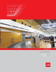
Catalog 1.1.1<br />
Swirl diffuser<br />
<strong>DAL</strong> <strong>358</strong>
Concordia University, Montréal, Canada
<strong>NAD</strong> <strong>Klima</strong><br />
<strong>DAL</strong> <strong>358</strong> model<br />
<strong>DAL</strong> <strong>358</strong> 1<br />
<strong>DAL</strong> <strong>358</strong> 2<br />
Method of operation . . . . . . . . . . . . . . . . . . . . . . . . . . . . . . . . . . . . . . . . . . . . <strong>DAL</strong> <strong>358</strong> 3<br />
Flow and direction of the air . . . . . . . . . . . . . . . . . . . . . . . . . . . . . . . . . . . . . . <strong>DAL</strong> <strong>358</strong> 5<br />
Range of application and Quick selection . . . . . . . . . . . . . . . . . . . . . . . . <strong>DAL</strong> <strong>358</strong> 6<br />
Diagrams of performance. . . . . . . . . . . . . . . . . . . . . . . . . . . . . . . . . . . . . . . . <strong>DAL</strong> <strong>358</strong> 7<br />
Dimensions and Weight . . . . . . . . . . . . . . . . . .. . . . . . . . . . . . . . . . . . . . . . . <strong>DAL</strong> <strong>358</strong> 11<br />
<strong>DAL</strong> <strong>358</strong> 12<br />
<strong>DAL</strong> <strong>358</strong> 13<br />
<strong>DAL</strong> <strong>358</strong> 14<br />
content<br />
1.1.1 <strong>DAL</strong> <strong>358</strong> C
Cafeteria, CIMA+ ing. , Sherbrooke, Québec
<strong>NAD</strong> <strong>Klima</strong><br />
Swirl Diffuser<br />
Description, Areas of application and Benefits<br />
<strong>DAL</strong> <strong>358</strong> Swirl diffuser<br />
The <strong>DAL</strong> <strong>358</strong> is a high induction swirl<br />
airflow diffuser with a circular or<br />
square front plate. It has eccentric<br />
ABS cylinders and profiles controlling<br />
air stream.<br />
The <strong>DAL</strong> <strong>358</strong> permits optimal adaptation<br />
of the ventilation system to<br />
prevailing room requirements.<br />
Eccentric cylinders integrated into<br />
the front plate permit a variety of<br />
airstream configurations, even after<br />
installation.<br />
The <strong>DAL</strong> <strong>358</strong> technology provides<br />
high speed discharge air with relatively<br />
low sound power.<br />
The swirl airstream, the stability and<br />
the high induction generated from<br />
the very start of the discharge slot<br />
make the <strong>DAL</strong> <strong>358</strong> the diffuser of<br />
choice for high air flow rates and<br />
variable air volumes.<br />
Areas of application<br />
-High flow rate zones<br />
-Comfort zones<br />
-Offices with closed work spaces<br />
-Offices and clean rooms<br />
-Administrative centres<br />
-Computer(class-)rooms<br />
-Meeting rooms<br />
-Multi-purpose rooms<br />
-Systems with constant or variable<br />
airflow rates<br />
-Entrance halls (vertical air blast)<br />
Product benefits<br />
- Rapid reduction of speeds and<br />
temperature variations caused by<br />
high induction<br />
- Low sound power for high air flow<br />
rates<br />
- Stable swirl airflow and a variety of air<br />
blasts available in 1-2-3 directions<br />
- Eccentric cylinders allowing 1800 air<br />
blast adjustment<br />
- Possibility of changing airflow, even<br />
after installation<br />
- Possibility of reducing total airflow<br />
rate as much as 25% in VAV<br />
- Three times as much induction<br />
as a conventional 4-way diffuser<br />
- Possibility of eliminating peripheral<br />
heating due to diffuser heating<br />
- Fewer diffusers required<br />
- Possibility of reducing total air<br />
volumes of the various units, while<br />
meeting requirements<br />
in air mix quantity<br />
- Possibility of adapting to systems<br />
requiring constant or variable airflow<br />
rates<br />
Subject to technical changes. Version 04 / 06 / 2012<br />
1.1.1 <strong>DAL</strong> <strong>358</strong> 1
<strong>NAD</strong> <strong>Klima</strong><br />
Swirl Diffuser<br />
<strong>DAL</strong> <strong>358</strong> Configuration<br />
Whether on a square or circular front<br />
plate, the slots for the eccentric<br />
cylinders are generally arranged in a<br />
star pattern.<br />
<strong>DAL</strong> <strong>358</strong>-Q-300/400<br />
<strong>DAL</strong> <strong>358</strong>-Q-300/603<br />
<strong>DAL</strong> <strong>358</strong>-R-300<br />
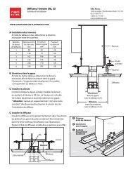
The diffuser is mounted on a plenum.<br />
Up to a nominal size of 800, the front<br />
plate is secured by a concealed<br />
middle screw. In the case of the DN<br />
60 however, a reinforcement crossbar<br />
is required to secure the plate.<br />
Only the DN 800 has a different fastening<br />
configuration; screws are fastened<br />
at the 4 corners of the plate<br />
<strong>DAL</strong> <strong>358</strong>-Q-400/400<br />
<strong>DAL</strong> <strong>358</strong>-Q-400/603<br />
<strong>DAL</strong> <strong>358</strong>-R-400<br />
<strong>DAL</strong> <strong>358</strong>-Q-500/502<br />
<strong>DAL</strong> <strong>358</strong>-Q-500/603<br />
<strong>DAL</strong> <strong>358</strong>-R-500<br />
<strong>DAL</strong> <strong>358</strong>-Q-600/603<br />
<strong>DAL</strong> <strong>358</strong>-R-600<br />
<strong>DAL</strong> <strong>358</strong>-Q-800/800<br />
<strong>DAL</strong> <strong>358</strong>-R-800<br />
2 1.1.1 <strong>DAL</strong> <strong>358</strong><br />
Subject to technical changes. Version 23 / 08 / 2012
<strong>NAD</strong> <strong>Klima</strong><br />
Swirl Diffuser<br />
Method of operation<br />
The eccentric cylinders, 100 mm in<br />
length, can pivot a full 3600. In their<br />
initial position, (1A and F6), the<br />
airflow will deviate by 900 with a<br />
constant discharge blast . Turning<br />
the cylinders to positions 2 1 and 6 5,<br />
for example, will reduce the section<br />
without tapering off and the air blast<br />
will increase. Adjustments 2 1 and 6<br />
5 are standard for North America<br />
because of the multiple VAV applications<br />
(variable air volume).<br />
The eccentric cylinder, aided by the<br />
profiles of the slots, creates a powerful<br />
channel into which the air is<br />
drawn. When nearing the exit of the<br />
cylinder, air depression takes place.<br />
Air Flow Behaviour<br />
The <strong>DAL</strong> <strong>358</strong> frontal plate has slots<br />
arranged in a characteristic star<br />
pattern. Turning the cylinders individually<br />
can produce a multitude of<br />
airstream patterns. In this manner,<br />
obstacles to efficient air flow can be<br />
avoided (lamp bases, ceiling drops,<br />
architectural columns, etc....). When<br />
installing in high ceilings (>5 m), a<br />
portion of the cylinders in the centre<br />
of the slot must be directed to<br />
produce a vertical blast (see figure 1).<br />
Use of the <strong>DAL</strong> <strong>358</strong> does not require<br />
a closed ceiling installation in order<br />
to produce a stable horizontal<br />
airflow. Despite the variety of air flow<br />
directions, all shapes have more or<br />
less the same sound power and<br />
pressure drop because of the specific<br />
design of the eccentric cylinder .<br />
Controlling the direction of airflow<br />
Air flow<br />
Indexing range<br />
min. max.<br />
Direction of airflow<br />
Cylinder position 1A<br />
Cylinder position 2 1<br />
Cylinder position 4 3<br />
Swirl air blast<br />
When positioning all the cylinders on 1<br />
A, a rotating air blast under the ceiling<br />
is produced in a swirling stream,<br />
creating a strong induction current.<br />
(standard setting).<br />
One-Sided Blast<br />
This air flow is obtained by positioning<br />
all of the cylinders on 1 A.<br />
Two-Sided Blast<br />
This blast on two sides is obtained by<br />
positioning all cylinders of one half on<br />
1A and those of the other half on F6.<br />
Cylinder position CD<br />
Schema 1<br />
Subject to technical changes. Version 04 / 06 / 2012<br />
1.1.1 <strong>DAL</strong> <strong>358</strong> 3
CIMA+ ing. , Sherbrooke, Québec
<strong>NAD</strong> <strong>Klima</strong><br />
Swirl Diffuser<br />
Vmax = Vmax simulation X f<br />
∆Pt = ∆Pt simulation X f<br />
LWA[dB] = LWA[dB] simulation X f<br />
Flow and Direction of the air<br />
DN 600 360° helical flow<br />
ST = Standard helical flow (2 1)<br />
HL = Flow high-rise (>5m)<br />
(exterior 21 and center C D )<br />
VF = Vertical flow (C D)<br />
DN 300<br />
DN 600 180° 3-way helical<br />
3W = Flow 180° (wall) (2 1 - 3 4)<br />
DN 300<br />
DN 400<br />
DN 400<br />
DN 500<br />
DN 500<br />
DN 600<br />
Position 4 3<br />
Position 2 1<br />
DN 600<br />
Correction factor : f<br />
V MAX 1.0<br />
∆Pt 1.0<br />
L WA [dB] 1.0<br />
DN 800<br />
Correction factor : f<br />
V MAX 1.2<br />
∆Pt 1.3<br />
L WA [dB] 1.1<br />
DN 800<br />
DN 600 3-way 90˚<br />
3C = Flow 90° (corner) (2 1)<br />
DN 300<br />
DN 600 2 -way corner<br />
2L = Flow on both side by L<br />
(2 corridors) (2 1)<br />
DN 300<br />
DN 400<br />
DN 400<br />
DN 500<br />
DN 500<br />
DN 600<br />
DN 600<br />
Correction factor : f<br />
V MAX 1.4<br />
∆Pt 1.0<br />
L WA [dB] 1.0<br />
DN 800<br />
Correction factor : f<br />
V MAX<br />
∆Pt<br />
L WA [dB]<br />
1.7<br />
1.0<br />
1.0<br />
DN 800<br />
DN 600 2 opposite ways DN 600 1 way<br />
DN 300<br />
2W = Flow on two opposite sides (2 1 - 5 6)<br />
1W = Flow on one side (2 1)<br />
DN 300<br />
DN 400<br />
DN 400<br />
DN 500<br />
DN 500<br />
DN 600<br />
DN 600<br />
Correction factor : f<br />
V MAX 1.7<br />
∆Pt 1.0<br />
L WA [dB] 1.0<br />
DN 800<br />
Correction factor : f<br />
V MAX<br />
∆Pt<br />
L WA [dB]<br />
2.0<br />
1.0<br />
1.0<br />
DN 800<br />
Subject to technical changes. Version 08 / 05 / 2012<br />
1.1.1 <strong>DAL</strong> <strong>358</strong> 5
<strong>NAD</strong> <strong>Klima</strong><br />
Swirl Diffuser<br />
Range of application - Quick selection for <strong>DAL</strong> <strong>358</strong><br />
Height of<br />
the room<br />
Air flow by surface<br />
m 3 /h/m 2<br />
cfm/sq ft<br />
Nominal<br />
size<br />
DN<br />
Quantity of<br />
diffusers<br />
Airflow by diffuser<br />
m 3 /h<br />
cfm<br />
Min. distance<br />
diffuser<br />
(m)<br />
Min. distance<br />
wall<br />
(m)<br />
Critical<br />
X<br />
(m)<br />
Pressure<br />
difference<br />
∆P (Pa)<br />
Acoustic<br />
Power level<br />
Lw(dBA)<br />
9 0.5 DN 400 4 228 134 1.3 0.7 1.4 25 36<br />
2.44 m<br />
(8 ft) 1<br />
15<br />
27<br />
37<br />
2<br />
0.8<br />
1.5<br />
2<br />
DN 500<br />
DN 600<br />
DN 600<br />
3<br />
4<br />
4<br />
6<br />
366<br />
660<br />
609<br />
215<br />
388<br />
<strong>358</strong><br />
2.2<br />
4.2<br />
3.5<br />
6<br />
1.2<br />
2.2<br />
1.8<br />
7<br />
1.4<br />
1.9<br />
1.7<br />
25<br />
32<br />
26<br />
36<br />
43<br />
39<br />
9 0.5 DN 400 4 228 134 0.2 0.1 1.4 25 36<br />
3.05 m 15 0.8 DN 500 4 366 215 0.8 0.5 1.4 25 36<br />
(10 ft)<br />
27 1.5 DN 600 4 685 403 2.8 1.5 1.9 32 43<br />
37 2 DN 600 6 609 <strong>358</strong> 2.2 1.2 1.7 26 39<br />
9 0.5 DN 500 2 457 269 0.1 0.1 1.7 36 42<br />
4.0 m<br />
(13 ft)<br />
15<br />
27<br />
0.8<br />
1.5<br />
DN 500<br />
DN 600<br />
4<br />
4<br />
366<br />
685<br />
215<br />
403<br />
0.1<br />
0.8<br />
0.1<br />
0.6<br />
1.4<br />
1.9<br />
25<br />
32<br />
36<br />
43<br />
37 2 DN 800 4 914 537 1.6 0.9 1.8 28 44<br />
**Lw(dBA) : The absorption of the room is not considered. Column for any room from that height at the same volume of air by diffuser<br />
Column in reference to the example<br />
Specifications :<br />
- Room: L x W x H = 10 m x 10 m x 2.44m<br />
( 33 ft x 33 ft x 8 ft)<br />
- Total air flow in the room : 1550 cfm<br />
4<br />
- Initial temperature difference: ∆T = -10°C<br />
- Air velocity : 1.8 m = 0.25 m/s (50 cfm)<br />
- VAV : 25%<br />
Using the data on ceiling height 1 and airflow<br />
rate by surface (m 2 or sq. ft. 2 ), 2 choose the<br />
nominal size (DN) of the <strong>DAL</strong> <strong>358</strong>. 3<br />
Divide the total airflow rate of the room 4 by<br />
the ideal value of the air flow rate for the<br />
selected size. Adjust the quantity of diffusers to<br />
achieve symmetry in the room while respecting<br />
the maximum airflow rate in the optimal setting<br />
range. 5 Watch for minimal distance between<br />
diffusers and between diffusers 6 and walls. 7<br />
Connector diameter<br />
ød<br />
mm inches<br />
Location of the diffusers<br />
= minimum range of application<br />
= Optimal range of application<br />
(For minimum application in V.A.V.)<br />
(Maximum standard volume for<br />
office building)<br />
1.8 m (6 ft) Y<br />
Airflow pattern<br />
comfort line<br />
Scale grid: 1 m Blue: Air velocity >= 0.25 [m/s]<br />
= Maximal range of application<br />
(Noise level higher than 33 (43-10) dBA)<br />
300 12 DN 800<br />
opt<br />
540*<br />
250 10 DN 600<br />
opt 360*<br />
5<br />
200 8 DN 500<br />
opt<br />
240*<br />
150 6 DN 400<br />
opt<br />
130*<br />
150 6 DN 300<br />
opt 65*<br />
* Ideal operating value in cfm<br />
cfm<br />
L/s<br />
m /h<br />
Airflow<br />
20 30 40 50 60 70 80 100<br />
150 200 280 300 350 400 500 600 1000<br />
10 15 20 24 28 33 37 47 70 94 132 142 165 188 235<br />
283 472<br />
34 51 68 85 102 119 136 170 255 340 475 510 595 680 850 1020 1700<br />
V . Subject to technical changes. Version 10/ 04 / 2013<br />
6 1.1.1 <strong>DAL</strong> <strong>358</strong>
<strong>NAD</strong> <strong>Klima</strong><br />
Swirl Diffuser<br />
Stream rating diagram<br />
Notes :<br />
Room absorption is not factored in.<br />
For a comparison with North American values,<br />
reduce sound power by 10.<br />
Flow sub-ceiling<br />
Airflow V·<br />
CFM<br />
92<br />
[m /h]<br />
25 30 35 40 45 55 60 = L WA [dB(A)]<br />
2<br />
= L WA [dB(A)]<br />
= L WA [dB(A)]<br />
1 3<br />
L WA [dB(A)] =<br />
L WA [dB(A)] =<br />
Airflow distance after conjunction (y [m])<br />
11.5 10 8 6.5 5 3.25<br />
5<br />
1.5 0 Ft<br />
33<br />
in./H 2 O<br />
Pressure loss Pt [Pa]<br />
.04<br />
.08<br />
4<br />
.12<br />
.16<br />
.20<br />
.24<br />
.28<br />
.32<br />
.36<br />
.40<br />
29.5<br />
26<br />
23<br />
20<br />
16<br />
20<br />
m/s ft/min<br />
13<br />
30<br />
40<br />
10<br />
7<br />
60<br />
6<br />
8<br />
6.5<br />
5<br />
3.25<br />
Airflow distance x [m]<br />
Airflow velocity v max<br />
80<br />
100<br />
120<br />
140<br />
160<br />
180<br />
200<br />
<strong>DAL</strong> <strong>358</strong> - 8<br />
Subject to technical changes. Version 10 / 04 / 2013<br />
1.1.1 <strong>DAL</strong> <strong>358</strong> 7
<strong>NAD</strong> <strong>Klima</strong><br />
Swirl Diffuser<br />
Airflow performance diagram and Example<br />
Critical airflow distance<br />
DN400 et DN300<br />
Critical airflow distance x crit [m] Critical airflow distance x crit [m]<br />
10<br />
<strong>DAL</strong> <strong>358</strong> - DN 400 / 300<br />
Airflow V·<br />
Airflow V·<br />
∆T<br />
Temperature difference<br />
(0) (100) (200) (300) (400) (500)<br />
Critical airflow distance x crit [m]<br />
[m /h] Airflow V·<br />
∆T<br />
Temperature difference<br />
°C<br />
°C<br />
°C<br />
°C<br />
°C<br />
°C<br />
°C<br />
°C<br />
°C<br />
°C<br />
x crit [m] (DN300)<br />
Critical airflow distance x crit [m]<br />
[m /h] Airflow V·<br />
<strong>DAL</strong> <strong>358</strong> - DN 500<br />
[m /h]<br />
[m /h]<br />
∆T<br />
Temperature difference<br />
<strong>DAL</strong> <strong>358</strong> - DN 600 <strong>DAL</strong> <strong>358</strong> - DN 800<br />
∆T<br />
Temperature difference<br />
°C<br />
°C<br />
°C<br />
°C<br />
°C<br />
°C<br />
Temperature ratio<br />
°C<br />
°C<br />
°C<br />
°C<br />
Specifications :<br />
Height of ceiling:<br />
H= 3.00 m<br />
Airflow rate by diffuser: V O = 600 m3/h<br />
Maximum cooling:<br />
∆T 0 = -10°C<br />
Distance between diffusers: 2 x 1.7 = 3.4m<br />
Requirements:<br />
1. Nominal size of diffuser<br />
2. Sound power L WA<br />
3. Pressure drop ∆pt<br />
4. Maximum air velocity at nominal head<br />
level (1.8 m)<br />
5. Maximum temperature variation of<br />
ambient air at nominal head level<br />
6. Critical path of airflow (blast detaching<br />
itself from ceiling when cooling)<br />
Solution:<br />
1.From diagram" Range of Applications"<br />
we note the nominal size of DN600 1<br />
2, 3. From diagram "Airflow from Ceiling"<br />
for the DN 600 as diffuser and an airflow rate<br />
of 600 m3/h 2 we note the following values:<br />
Sound power: 39dB 3 (29 dB when factoring<br />
in room absorption)<br />
Total pressure drop: 25 Pa 4<br />
4. At nominal head level<br />
y = H - 1.80 = (3.00 m - 1.80 m = 1.20 m)<br />
and a horizontal airflow path of<br />
x-1.7 m<br />
0.18 m/s<br />
6<br />
7<br />
we note a maximum air velocity of<br />
5. For an airflow distance of<br />
(x+y) = 1.70 m + 1.20 m = 2,90 m 8<br />
and a DN 600, we note a temperature ratio of<br />
0.062°C 9 . The maximum temperature<br />
variation reached between room air and air<br />
blast at head level is 0.062 x 10°C = -0.62°C.<br />
5<br />
9<br />
6. From diagram "Critical Distance of Airflow"<br />
and an airflow rate of 600 m3/h with an initial<br />
temperature variation of ∆T0 =-10°C<br />
we come to a critical distance of airflow Xcrit<br />
= 1.7 m. 10<br />
∆Txy<br />
∆T<br />
8<br />
300<br />
x bzw. x + y [m]<br />
8 1.1.1 <strong>DAL</strong> <strong>358</strong><br />
Subject to technical changes. Version 13 / 08 / 2012
Laval University, Québec, Canada
TVA, Montréal, Canada
<strong>NAD</strong> <strong>Klima</strong><br />
Swirl Diffuser<br />
Dimensions<br />
<strong>DAL</strong><strong>358</strong> Dimension / Weight Square plenum <strong>DAL</strong><strong>358</strong> Dimension / Weight Round plenum<br />
Size DN 300/400 500 600 800 Size DN 300/400 500 600 800<br />
Cote A 400 502 603 800<br />
Cote B 76 82 68 66<br />
Cote C 251 312 347 411<br />
Cote ØD 150 200 250 300<br />
Cote E 12 12 12 12<br />
Cote F 387 488 584 790<br />
Poids [Kg] 5.2 7.1 11.5 14.6<br />
A eff [m 2 ] 0.0080/0.0134 0.0214 0.0347 0.0508<br />
Size ØA 400 500 600 800<br />
Size B 76 82 67 66<br />
Size C 252 312 347 411<br />
Size ØD 150 200 250 300<br />
Size E 8 8 8 8<br />
Size Ø F 392 492 592 792<br />
Weight [Kg] 4.2 6.2 8.5 14.1<br />
A eff [m 2 ] 0.0080/0.0134 0.0214 0.0347 0.0508<br />
with square plenum - lateral input<br />
Suspension hole, 4 x Ø6.3<br />
with round plenum - lateral input<br />
Suspension bracket (3)<br />
Flow control<br />
(optional)<br />
ØD<br />
Flow control<br />
(optional)<br />
Perfored metal sheet<br />
Perfored<br />
metal sheet<br />
B<br />
E<br />
C<br />
14<br />
F<br />
A<br />
Ø F<br />
Ø A<br />
with square plenum - top input<br />
ØD<br />
with round plenum - top input<br />
Flow control<br />
(optional)<br />
Flow control<br />
(optional)<br />
Perfored<br />
metal sheet<br />
C<br />
Perfored<br />
metal sheet<br />
E<br />
ØD<br />
C<br />
B<br />
E<br />
8<br />
ØD<br />
C<br />
E<br />
F<br />
A<br />
8<br />
Ø F<br />
Ø A<br />
Subject to technical changes. Version 22 / 05 / 2013<br />
1.1.1 <strong>DAL</strong> <strong>358</strong> 11
<strong>NAD</strong> <strong>Klima</strong><br />
Swirl Diffuser<br />
Correction factor of air flow<br />
for a reading with balometer<br />
To ensure adequate balancing of <strong>DAL</strong> <strong>358</strong><br />
type diffusers, it is recommended<br />
to use the correction factors of the<br />
airflow rate equivalent to the resistance<br />
generated by the balometer.<br />
These factors are valid for a ventilation<br />
system comprising at least 3 diffusers<br />
after a VAV unit or box. For less than 3<br />
diffusers with an automatic airflow rate<br />
setting, factors are lower than the stated<br />
ones.<br />
Such as indicated in the ALNOR manual,<br />
Appendix B - "Capture Hood Flow<br />
Resistance", the instrument's manufacturer<br />
recommends taking a reading at the<br />
ventilation duct and comparing it with<br />
one taken under the diffuser, with or<br />
without the balometer, in order to<br />
determine the correction factor.<br />
In order to avoid this procedure, we<br />
provide herein the correction factors<br />
needed for all <strong>DAL</strong> <strong>358</strong> diffuser models.<br />
<strong>DAL</strong> <strong>358</strong> - DN 300<br />
<strong>DAL</strong> <strong>358</strong> - DN 400<br />
100 50<br />
120 140 160 180 200 220 240 260 280 300 320 100 140 180 220 260 300 340<br />
120 160 200 240 280 320 360<br />
Adjustment: Helical - adjustment 21<br />
90<br />
80<br />
70<br />
Adjustment: Helical - adjustment 21<br />
160<br />
150<br />
140<br />
130<br />
60<br />
120<br />
50<br />
110<br />
40<br />
30<br />
20<br />
10<br />
100<br />
90<br />
80<br />
70<br />
10 20 30 40 50 60 70 80 90 80 90 100 110 120 130 140 150<br />
Air flow - Balometer (cfm)<br />
Air flow - Balometer (cfm)<br />
Balometer (cfm) 20 29 57 70 74 Balometer (cfm) 80 98 115 132 140<br />
Factor 1.00 1.01 1.05 1.06 1.07<br />
Factor 1.00 1.02 1.04 1.06 1.07<br />
Actual flow (cfm) 20 30 60 75 80 Actual flow (cfm) 80 100 120 140 150<br />
<strong>DAL</strong> <strong>358</strong> - DN 500<br />
Adjustment: Helical - adjustment 21<br />
400<br />
350<br />
300<br />
250<br />
200<br />
150<br />
<strong>DAL</strong> <strong>358</strong> - DN 600<br />
Adjustment: Helical - adjustment 21<br />
450<br />
400<br />
350<br />
300<br />
250<br />
200<br />
150<br />
100<br />
Air flow - Balometer (cfm)<br />
Air flow - Balometer (cfm)<br />
Balometer (cfm) 147 192 230 250 300 Balometer (cfm) 94 185 270 310 330<br />
Factor 1.02 1.04 1.08 1.12 1.13<br />
Factor 1.06 1.08 1.11 1.16 1.21<br />
Actual flow (cfm) 150 200 250 280 340 Actual flow (cfm) 100 200 300 350 400<br />
Actual flow at diffuser (cfm)<br />
Actual flow at diffuser (cfm)<br />
<strong>DAL</strong> <strong>358</strong> - DN 800<br />
Adjustment: Helical - adjustment 21<br />
650<br />
600<br />
550<br />
500<br />
450<br />
400<br />
350<br />
300<br />
250<br />
250 275 300 325 350 375 400 425 450 475 500<br />
Air flow - Balometer (cfm)<br />
Balometer (cfm) 360 392 415 446 480<br />
Factor 1.11 1.14 1.20 1.23 1.25<br />
Actual flow (cfm) 400 450 500 550 600<br />
Actual flow at diffuser (cfm)<br />
Actual flow at diffuser (cfm)<br />
Actual flow at diffuser (cfm)<br />
Identification Chart<br />
Y<br />
X<br />
DN<br />
300<br />
400<br />
500<br />
600<br />
800<br />
X (mm)<br />
603<br />
603<br />
603<br />
603<br />
803<br />
Y(mm)<br />
355<br />
355<br />
455<br />
552<br />
755<br />
12 1.1.1 <strong>DAL</strong> <strong>358</strong><br />
Subject to technical changes. Version 04 / 06 / 2012
<strong>NAD</strong> <strong>Klima</strong><br />
1 - Description and Physical Characteristics<br />
steel. Integrated slots in the frontal plate (circular or<br />
square) hold eccentric cylinders ensuring a high induc-<br />
1.2 The eccentric cylinders, 100 mm in length, are individually<br />
adjustable by rotating as much as 360°, each one<br />
on its own axis, inside the front plate. This design allows<br />
for a multitude of adjustments covering the range of air<br />
°<br />
360°).<br />
3 - Connection<br />
manufacturer. The plenum is made of 24-gauge galvanized<br />
steel and comprises a perforated stabilizing<br />
suspension points in accordance with paraseismic<br />
standards are provided. The input brace is centered on<br />
the side or on the top of the plenum, and its size is made<br />
The joints of the plenum are sealed with silicone caulking<br />
free of VOC emissions.<br />
ceiling or classic gypsum ceilings.<br />
(<strong>DAL</strong> <strong>358</strong> R and <strong>DAL</strong> <strong>358</strong> Q)<br />
1.4 Every plate is coated inside and outside with a baked<br />
polyester TGIC-enamel paint, providing a smooth,<br />
colour from the RAL colour chart or among special-order<br />
colours.<br />
1.5 Eccentric cylinders are available in black or white.<br />
4 - Balancing<br />
4.1 Balancing of the <strong>DAL</strong> <strong>358</strong> diffusers must be executed by<br />
a technician trained in ventilation system balancing with<br />
a professional certificate.<br />
4.2 The technician must take into consideration the correction<br />
factor for use of a balometer when regulating air<br />
volume.<br />
5 - Quality required: <strong>NAD</strong> <strong>Klima</strong>, model <strong>DAL</strong> <strong>358</strong><br />
2 -Performance<br />
even in situations requiring variable air volume -- in order<br />
the room (∆TXY = TR - TXY) and the initial temperature<br />
variation (∆TO = TR - TO). This ratio must perform a<br />
minimum of ∆TXY ÷ ∆TO ≤ 0.1.<br />
-<br />
tion software. This software indicates the pressure drop<br />
and sound power generated as well as a cross-sectional<br />
isothermal and heating modes. Upon demand from the<br />
engineer, the software can demonstrate a nominal<br />
velocity in an occupied zone of 0.25 m/s and can adapt to<br />
various requirements of air volume (25% to 100% of<br />
mode.<br />
Subject to technical changes. Version 04 / 06 / 2012<br />
1.1.1 <strong>DAL</strong> <strong>358</strong> 13
<strong>NAD</strong> <strong>Klima</strong><br />
<strong>DAL</strong> <strong>358</strong><br />
Product<br />
Q = Square<br />
R = Round<br />
300, 400, 500, 600, 800<br />
400, 502, 603, 800<br />
Nominal size<br />
(603 for 24''X24'' T-bar) Outer size<br />
HL = Flow high-rise (>5m) (exterior 21 and center CD)<br />
VF =<br />
1W = Flow on one side (2 1)<br />
2W = Flow on two opposite sides (2 1 - 5 6)<br />
2L = Flow on both side by L (2 corridors) (2 1)<br />
3C = Flow 90° (corner) (2 1)<br />
3W = Flow 180° (wall) (2 1 - 3 4)<br />
W = White roll and receptacle (RAL 9003)<br />
C = Cream roll and receptacle (RAL 9010)<br />
B = Black roll and receptacle<br />
X = Without roll<br />
9003 = White<br />
9010 = Cream<br />
_____ = RAL colour * (write the number of RAL colour)<br />
S = Plenum with lateral input<br />
T = Plenum with top input<br />
X = Without plenum<br />
X = Without insulation<br />
I = With acoustic insulation<br />
F =<br />
et<br />
X = Without damper<br />
D = With damper (for gypsum ceiling)<br />
Color of roll<br />
and receptacle<br />
Colour ( front plate)<br />
Plenum<br />
Insulation<br />
Damper<br />
<strong>DAL</strong><strong>358</strong> - Q - 300 - 400 - ST - W - 9003 - S - X - X<br />
Example<br />
Notes :<br />
Blue : Standard, in stock<br />
Write the number of 4 digits of the RAL color chart<br />
Our powder paint colors are available in the RAL color chart only.<br />
14 1.1.1 <strong>DAL</strong> <strong>358</strong><br />
Subject to technical changes. Version 23 / 08 / 2012
Concordia University, Montréal, Canada
www.nadklima.com<br />
<strong>NAD</strong> <strong>Klima</strong> 144, Léger Street, Sherbrooke (Québec), Canada J1L 1L9 • T : 819 780-0111 • 1 866 531-1739 • F : 819 780-1660 • info@nadklima.com