VIVISUN LED The Complete Switch - Aerospace Optics
VIVISUN LED The Complete Switch - Aerospace Optics
VIVISUN LED The Complete Switch - Aerospace Optics

You also want an ePaper? Increase the reach of your titles
YUMPU automatically turns print PDFs into web optimized ePapers that Google loves.
<strong>VIVISUN</strong><br />
<strong>LED</strong><br />
<strong>The</strong> <strong>Complete</strong> <strong>Switch</strong><br />
SUNLIGHT<br />
READABLE<br />
<strong>LED</strong><br />
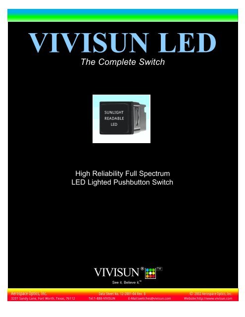
High Reliability Full Spectrum<br />
<strong>LED</strong> Lighted Pushbutton <strong>Switch</strong><br />
®<br />
<strong>VIVISUN</strong><br />
See it. Believe it. TM<br />
TM<br />
<strong>Aerospace</strong> <strong>Optics</strong>, Inc. Data Sheet No. 12-2001-04 Rev. B 2002 <strong>Aerospace</strong> <strong>Optics</strong>, Inc.<br />
3201 Sandy Lane, Fort Worth, Texas, 76112 Tel:1-888-<strong>VIVISUN</strong> E-Mail:switches@vivisun.com Website:http://www.vivisun.com
<strong>VIVISUN</strong> <strong>LED</strong><br />
<strong>The</strong> <strong>Complete</strong> <strong>Switch</strong> TM<br />
High Reliability <strong>LED</strong> Lighted <strong>Switch</strong>es<br />
Life-of-the-Platform Service Life<br />
Maintenance Free Operation<br />
Low Power and Low Touch Temperature<br />
Now with Voltage-Controlled Dimming<br />
and a Spectrum TM<br />
of Sunlight Readable Colors<br />
Designed, tested and qualified to MIL-PRF-22885/108<br />
Listed on the Qualified Products List (QPL) 22885<br />
®<br />
<strong>VIVISUN</strong><br />
See it. Believe it. TM<br />
TM<br />
<strong>Aerospace</strong> <strong>Optics</strong>, Inc. Data Sheet No. 12-2001-04 Rev. B 2002 <strong>Aerospace</strong> <strong>Optics</strong>, Inc. Page 1<br />
3201 Sandy Lane, Fort Worth, Texas, 76112 Tel:1-888-<strong>VIVISUN</strong> E-Mail:switches@vivisun.com Website:http://www.vivisun.com
<strong>VIVISUN</strong><br />
®<br />
L E D<br />
<strong>The</strong> <strong>Complete</strong> <strong>Switch</strong><br />
Photo: Courtesy of Lockheed<br />
Martin Missile and Fire Control<br />
D<br />
esign engineers in today’s aerospace<br />
industry are faced with the challenge of<br />
designing performance oriented avionic systems<br />
with high reliability. In pursuit of this<br />
goal they have wanted to design out low reliability,<br />
failure prone incandescent lighting in<br />
favor of <strong>LED</strong> (Light Emitting Diode) lighting<br />
which has the advantage of high reliability.<br />
However, they had previously found<br />
that in using <strong>LED</strong>s they had to sacrifice quality<br />
lighting and had to employ complex pulse<br />
width modulation techniques for uniform<br />
low level dimming. <strong>Aerospace</strong> <strong>Optics</strong> has<br />
responded to this need by developing a product<br />
to help these design engineers with their<br />
need for quality lighting, high reliability and<br />
simple voltage-controlled dimming in lighted<br />
pushbutton switches.<br />
<strong>VIVISUN</strong> <strong>LED</strong><br />
<strong>The</strong> <strong>VIVISUN</strong> <strong>LED</strong> is an <strong>LED</strong> lighted<br />
pushbutton switch that combines the excellent<br />
sunlight readability our customers<br />
expect from <strong>VIVISUN</strong> products with the<br />
high reliability afforded by <strong>LED</strong>s. This product<br />
was developed to solve the problems<br />
faced by our customers who have wanted<br />
<strong>LED</strong> reliability but have been unable to get<br />
<strong>LED</strong> reliability with high quality lighting.<br />
<strong>The</strong> <strong>VIVISUN</strong> <strong>LED</strong> high performance<br />
lighting provides sunlight readability exceeding<br />
the requirements of MIL-PRF-22885F,<br />
compliance with the NVIS requirements of<br />
MIL-L-85762A, voltage dimming and<br />
impressive uniformity and viewing angle.<br />
<strong>The</strong>se advanced technology switches and<br />
indicators are setting new industry standards<br />
for <strong>LED</strong> lighting and these innovative<br />
switches are available only from <strong>Aerospace</strong><br />
<strong>Optics</strong>, the technical leader in sunlight readable<br />
switches and indicators.<br />
<strong>VIVISUN</strong> <strong>LED</strong> in Multifunction Displays<br />
Electronic multifunction displays are being<br />
used in ground vehicles, on shipboard and in<br />
aircraft glass cockpits to display more and<br />
more instrumentation and control information.<br />
This has caused a reduction in the<br />
required numbers of individual pushbutton<br />
switches and indicators. However, there are<br />
many applications where lighted pushbutton<br />
switches are used to enhance electronic displays<br />
as shown in the photo above. In many<br />
cases these switches need a higher level of<br />
reliability and can be upgraded to <strong>VIVISUN</strong><br />
<strong>LED</strong> switches which offer the highest reliability,<br />
lowest maintenance and best sunlight<br />
readability available.<br />
<strong>The</strong> <strong>VIVISUN</strong> <strong>LED</strong> Advantage<br />
Lighted pushbutton switches and indicators<br />
have customarily used incandescent<br />
lamps to achieve high brightness and sunlight<br />
readability. Since the lighting is produced<br />
by the heating of a lamp filament<br />
whose radiant emissions are primarily heat,<br />
there are many problems resulting in low<br />
reliability. This leads to high failure rates for<br />
incandescent lamps requiring constant<br />
relamping resulting in high maintenance<br />
throughout the service life of the aircraft.<br />
In contrast, reliability has been the advantage<br />
for <strong>LED</strong>s making them highly desirable<br />
and serving as the answer to low reliability<br />
lamps. However, previous <strong>LED</strong> lighting has<br />
been a big disappointment because of its<br />
failure to provide good lighting for sunlight<br />
readability, uniformity, viewing angle and<br />
could only be dimmed uniformly using pulse<br />
width modulation. So, in spite of all the<br />
problems, incandescent lamps have continued<br />
to be used because of the need for high<br />
brightness and simple voltage dimming.<br />
<strong>The</strong> <strong>VIVISUN</strong> <strong>LED</strong> lighting advantage is<br />
that it eliminates the problems caused by<br />
incandescent lamps and it also solves the<br />
problems associated with <strong>LED</strong> lighting. <strong>The</strong><br />
<strong>VIVISUN</strong> <strong>LED</strong> lighting completely obsoletes<br />
incandescent lighting and truly fulfills<br />
the expectations for reliable <strong>LED</strong> lighting.<br />
<strong>The</strong> <strong>VIVISUN</strong> <strong>LED</strong> is the low power, high<br />
reliability solution to sunlight readable, NVIS<br />
compliant lighted pushbutton switches and<br />
indicators.<br />
<strong>The</strong> <strong>VIVISUN</strong> <strong>LED</strong> lighting eliminates<br />
the incandescent problems of high power<br />
consumption, high heat generation and high<br />
touch temperature by producing a brightness<br />
equivalent to incandescent while using less<br />
than half as much power. <strong>The</strong> poor reliability<br />
and high maintenance relamping problems<br />
associated with incandescent lamps are eliminated<br />
by using highly reliable, long life<br />
<strong>LED</strong>s in a fault tolerant circuit design. <strong>LED</strong>s<br />
are not susceptible to shock and vibration<br />
failures and do not have the high inrush current<br />
that incandescent lamps experience<br />
when energized. <strong>The</strong> <strong>VIVISUN</strong> <strong>LED</strong> lighting<br />
eliminates all of the incandescent lamp<br />
problems and still has high brightness, sunlight<br />
readability, viewing angle, uniformity,<br />
excellent color separation and is uniformly<br />
dimmable with voltage-controlled dimming.<br />
Listed on QPL 22885, ISO 9001 Registered<br />
<strong>The</strong> <strong>VIVISUN</strong> <strong>LED</strong> lighted pushbutton<br />
switches are fully qualified to MIL-PRF-<br />
22885/108 and listed on the Qualified<br />
Products List (QPL) 22885. Our Quality<br />
Assurance System is ISO 9001 registered and<br />
our test lab is DSCC certified. <strong>Aerospace</strong><br />
<strong>Optics</strong> is committed to manufacturing high<br />
quality products and to ensuring total customer<br />
satisfaction by providing outstanding<br />
customer service and defect-free products<br />
with exceptional delivery and product value.<br />
<strong>Aerospace</strong> <strong>Optics</strong>, Inc. Data Sheet No. 12-2001-04 Rev. B 2002 <strong>Aerospace</strong> <strong>Optics</strong>, Inc. Page 2<br />
3201 Sandy Lane, Fort Worth, Texas, 76112 Tel:1-888-<strong>VIVISUN</strong> E-Mail:switches@vivisun.com Website:http://www.vivisun.com
<strong>VIVISUN</strong><br />
®<br />
L E D <strong>The</strong> <strong>Complete</strong> <strong>Switch</strong><br />
Sunlight Readable and Non-Ghosting<br />
In complex glass cockpits, the workload<br />
and demand on the pilot is extensive and the<br />
possibility of misinterpreted annunciators cannot<br />
be tolerated. This has placed the sunlight<br />
readability of <strong>LED</strong> lighted switches and indicators<br />
at the highest priority. <strong>VIVISUN</strong> <strong>LED</strong><br />
switches and indicators meet these requirements<br />
head on, providing unconditional sunlight<br />
readability even in the most demanding<br />
direct sunlight conditions.<br />
<strong>VIVISUN</strong> <strong>LED</strong> lighted pushbutton<br />
switches and indicators are certified to meet<br />
the strict MIL-PRF-22885F requirements for<br />
sunlight readability. All <strong>VIVISUN</strong> <strong>LED</strong> standard<br />
colors have on to background contrasts<br />
greater than or equal to 0.6 in an ambient illumination<br />
of 10,000 foot-candles. This contrast<br />
is also certified for all glare producing angles<br />
up to and including 15°.<br />
Another area of tremendous pilot concern<br />
is the possibility of “Ghost Legends” from<br />
unenergized displays. Direct sunlight can cause<br />
a false image to be reflected from an unlighted<br />
display, thus causing possible confusion and<br />
misinterpretation. <strong>The</strong> <strong>VIVISUN</strong> <strong>LED</strong> displays<br />
remain blacked out or “Dead Faced”<br />
when not energized and meet the MIL-PRF-<br />
22885F unlighted contrast requirement not to<br />
exceed the absolute value of 0.1 in an ambient<br />
illumination of 10,000 foot-candles.<br />
Dead<br />
Face<br />
Specifiying <strong>VIVISUN</strong> <strong>LED</strong> means combining<br />
unrivaled sunlight readability with the cool,<br />
reliable, low power operation of <strong>LED</strong>s.<br />
NVIS Compliant and Sunlight Readable<br />
Sunlight<br />
Readable<br />
Nighttime operations are now an integral<br />
part of military strategy. <strong>The</strong>se operations<br />
have presented many new challenges, including<br />
the requirment to safely navigate and select<br />
ground targets using only the available<br />
starlight. To accomplish these objectives, crew<br />
members wear Night Vision Imaging System<br />
(NVIS) goggles which greatly enhance and<br />
multiply the effects of starlight. <strong>VIVISUN</strong><br />
<strong>LED</strong> switches and indicators are ready to meet<br />
these new challenges by providing advanced<br />
cockpit lighting that is both NVIS compatible<br />
and sunlight readable.<br />
Conventional lighted switches and indicators<br />
cannot be used in an aircraft involved in<br />
nighttime operations because they are not<br />
compatible with the NVIS goggles. Light from<br />
these incompatible displays will be greatly multiplied<br />
and interfere with the normal operation<br />
of the NVIS goggles. This interference<br />
degrades the sensitivity of the NVIS goggles,<br />
making them no longer capable of starlight<br />
operations. To address the issue of NVIS<br />
compatibility, MIL-L-85762A, “Lighting,<br />
Aircraft, Interior, Night Vision Imaging<br />
System (NVIS) Compatible,” was written to<br />
define the requirements for all aircraft lighting<br />
that is to be used with the NVIS goggles.<br />
To make displays compliant with the<br />
MIL-L-85762A requirements, sophisticated<br />
filtering must be used. Improperly designed filters<br />
can lead to a reduction in the brightness<br />
and sunlight contrast of the display. <strong>The</strong><br />
<strong>VIVISUN</strong> <strong>LED</strong> provides NVIS compliant<br />
lighting without sacrificing sunlight readability.<br />
MIL-L-85762A is no longer an active specification<br />
and in some cases is being replaced by<br />
MIL-STD-3009. Still, MIL-L-85762A is the<br />
source for the NVIS compliance requirements<br />
that are restated as guidelines in the Aircraft<br />
Lighting Handbook, JSSG-2010-5 and the<br />
Interface Document ASC/ENFC 96-01.<br />
<strong>VIVISUN</strong> <strong>LED</strong> switches are certified to meet<br />
the color, NVIS radiance and the minimum 0.4<br />
lighted contrast requirements stated in the<br />
source document, MIL-L-85762A and MIL-<br />
STD-3009.<br />
Wide Viewing Angle<br />
<strong>The</strong> <strong>VIVISUN</strong> <strong>LED</strong> can be viewed clearly<br />
throughout a wide 60° cone, even when it is<br />
operated in direct sunlight.<br />
Low Power Consumption<br />
<strong>The</strong> high efficiency <strong>VIVISUN</strong> <strong>LED</strong> typically<br />
consumes only 1.18 watts at 28 volts, less<br />
than half the power of a typical 2.69 watt<br />
incandescent switch or indicator. <strong>VIVISUN</strong><br />
<strong>LED</strong> switches and indicators also do not have<br />
the high inrush current of incandescent lamps<br />
which can be ten times the steady state current.<br />
Low Touch Temperature<br />
Less than one third of the energy emitted<br />
by an incandescent lamp is visible to the eye.<br />
<strong>The</strong> remaining two thirds is radiated as heat<br />
which can cause a significant rise in the face<br />
cap temperature. <strong>The</strong> face cap temperature can<br />
even reach a level that can cause pain or injury<br />
if touched without gloves.<br />
<strong>The</strong> <strong>VIVISUN</strong> <strong>LED</strong> uses low power, solid<br />
state lighting that emits far more light than<br />
heat. This significantly lowers the face cap<br />
temperature compared to similar incandescent<br />
switches and indicators. In normal operation,<br />
the face cap temperature is only 48° C, which<br />
is barely perceptible to the touch.<br />
Wide Operating Temperature Range<br />
High performance military systems are<br />
expected to operate properly in a wide variety<br />
of climatic conditions. This is why the VIVI-<br />
SUN <strong>LED</strong> was designed and tested for operation<br />
from -40°C to +71°C.<br />
High Reliability<br />
Incandescent lamps used in lighted pushbutton<br />
switches and indicators are troublesome.<br />
Extensive research into the nature of<br />
lamp failures revealed numerous factors affecting<br />
lamp life. <strong>The</strong>se factors include temperature,<br />
voltage, frequent on/off cycling and the<br />
vibration that is typical of high performance<br />
aircraft. Individually, these factors are significant<br />
but when combined the result is often<br />
unacceptably low lamp life.<br />
<strong>The</strong> solid state circuitry used in the VIVI-<br />
SUN <strong>LED</strong> incorporates advanced design features<br />
for high reliabilty and low drive current.<br />
<strong>The</strong>se advanced features result in a pushbutton<br />
cap calculated reliability per MIL-HDBK-<br />
217F, Notice 2 in excess of 125,000 hours. <strong>The</strong><br />
design of the <strong>VIVISUN</strong> <strong>LED</strong> even includes<br />
fault tolerance to keep the display readable<br />
even if an <strong>LED</strong> failure should occur.<br />
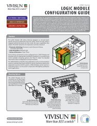
Single Common or Horizontally Split<br />
Commons<br />
<strong>The</strong> standard <strong>VIVISUN</strong> <strong>LED</strong> provides<br />
four power inputs, one for each of the display<br />
quadrants and a single common shared by all<br />
four. <strong>The</strong> horizontal split common option provides<br />
two commons, one for the upper and<br />
one for the lower half of the display.<br />
<strong>LED</strong> Polarity<br />
<strong>LED</strong>s are PN junction semiconductors<br />
that are inherently sensitive to polarity. <strong>The</strong><br />
<strong>VIVISUN</strong> <strong>LED</strong> is available in either Common<br />
Cathode (positive seeking) or Common Anode<br />
(negative seeking) configurations, each having<br />
reverse polarity protection.<br />
Reduced Number of Input Wires<br />
Many lighted switches require connecting<br />
as many as six wires to illuminate the entire<br />
display which can increase wiring complexity<br />
and aircraft weight. <strong>The</strong> <strong>VIVISUN</strong> <strong>LED</strong><br />
reduces the number of input wires by offering<br />
optional interconnections between display<br />
quadrants. For single legend displays, this feature<br />
means that the entire display can be illuminated<br />
with only two wires reducing wiring<br />
complexity and aircraft weight.<br />
11 Sunlight Readable Colors<br />
<strong>The</strong> <strong>VIVISUN</strong> <strong>LED</strong> is available in eleven<br />
sunlight readable colors. <strong>The</strong> sunlight readable<br />
legends are Type S per MIL-PRF-22885F and<br />
are dead faced in direct sunlight and fully sunlight<br />
readable when energized. Colors available<br />
are blue, green, white, yellow and red as standard<br />
colors and NVIS blue, NVIS green A,<br />
NVIS green B, NVIS white, NVIS yellow and<br />
NVIS red for use with the NVIS goggles.<br />
<strong>Aerospace</strong> <strong>Optics</strong>, Inc. Data Sheet No. 12-2001-04 Rev. B 2002 <strong>Aerospace</strong> <strong>Optics</strong>, Inc. Page 3<br />
3201 Sandy Lane, Fort Worth, Texas, 76112 Tel:1-888-<strong>VIVISUN</strong> E-Mail:switches@vivisun.com Website:http://www.vivisun.com
<strong>VIVISUN</strong><br />
®<br />
L E D <strong>The</strong> <strong>Complete</strong> <strong>Switch</strong><br />
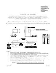
Dripproof/Watertight/Splashproof<br />
<strong>The</strong> <strong>VIVISUN</strong> <strong>LED</strong> 1 or 2 Pole, Type II<br />
and IV and 4 Pole Type VI enclosure designs<br />
meet the dripproof, watertight and splashproof<br />
requirements of MIL-PRF-22885F<br />
(paragraphs 4.7.20.1-3) and MIL-STD-108.<br />
<strong>The</strong> seal effectively prevents the leakage of<br />
water, sand and dust through the instrument<br />
panel.<br />
Each Type II, Type IV and Type VI unit is<br />
supplied with a mounting sleeve, sealed<br />
mounting spacer, sealed mounting flange and<br />
sealed cap. <strong>The</strong> seal is made from ZZ-R-765<br />
silicone rubber with a black matte finish.<br />
white legends on an obscure black background<br />
and when energized, the background illuminates<br />
in color and in excess of 200 foot-lamberts.<br />
Type W displays have visible black legends on a<br />
white background and when energized, the<br />
background illuminates in color and in excess of<br />
100 foot-lamberts. Type W displays are only<br />
available in the colors blue, green, white, yellow<br />
or red.<br />
Voltage-Controlled Dimming<br />
<strong>The</strong> <strong>VIVISUN</strong> <strong>LED</strong> uses an advanced electrical<br />
circuit design which provides voltage-controlled<br />
dimming from daylight conditions to<br />
nighttime flying levels with a simple change in<br />
input voltage.<br />
Uniformity<br />
advanced connector design has made possible<br />
the first ever use of CTS technology for lighted<br />
pushbutton switches and indicators.<br />
<strong>VIVISUN</strong><br />
<strong>LED</strong><br />
<strong>VIVISUN</strong><br />
<strong>LED</strong><br />
Lighted Legend, Visible White Displays<br />
<strong>The</strong> <strong>VIVISUN</strong> <strong>LED</strong> displays are available<br />
with always visible white legends on an opaque<br />
black background. Type N displays per MIL-<br />
PRF-22885F have always visible white legends<br />
that illuminate at 0.5 to 3.0 foot-lamberts when<br />
energized at rated voltage and are available in<br />
white, red, NVIS green A, NVIS green B or<br />
NVIS white. Type D displays have always visible<br />
white legends that illuminate in color and in<br />
excess of 100 foot-lamberts at rated voltage and<br />
are only available in the standard colors blue,<br />
green, white, yellow or red.<br />
Lighted Background Displays<br />
<strong>The</strong> <strong>VIVISUN</strong> <strong>LED</strong> displays are available<br />
with legends that do not light but the background<br />
surrounding the legends light when<br />
energized. Type B displays are hidden legend<br />
type per MIL-PRF-22885F and when energized<br />
the legend appears black and the background<br />
illuminates in color and in excess of 200 footlamberts.<br />
Type A displays have always visible<br />
<strong>The</strong> <strong>VIVISUN</strong> <strong>LED</strong> is designed to provide<br />
display legibility second to none with an<br />
average character to character luminance uniformity<br />
better than 2:1 at full rated voltage.<br />
Easy Installation<br />
Each <strong>VIVISUN</strong> <strong>LED</strong> unit is supplied with<br />
a mounting spacer and a mounting sleeve for<br />
simple, effortless installation. No loose screws<br />
or cumbersome tools behind the panel to<br />
worry about. All retaining hardware for the<br />
<strong>VIVISUN</strong> <strong>LED</strong> is provided internally, allowing<br />
easy mounting from the front of the<br />
instrument panel.<br />
<strong>VIVISUN</strong> <strong>LED</strong> Exclusive<br />
Solderless QUIK-CONNECT Module<br />
Since avionics hardware is seldom installed<br />
at the same time as its associated wiring harness,<br />
systems engineers are often faced with<br />
the inability to check correct component<br />
wiring until after the final connection is completed.<br />
Only the <strong>VIVISUN</strong> <strong>LED</strong> from<br />
<strong>Aerospace</strong> <strong>Optics</strong> offers a solution to these<br />
problems with the QUIK-CONNECT<br />
Common Termination System (CTS) connector.<br />
Our exclusive QUIK-CONNECT<br />
module makes wiring quick, easy and environmentally<br />
sealed. All electrical strands are<br />
crimped into standard MIL-C-39029/22-192<br />
contact sockets then inserted into the module<br />
using a M81969/14-10 insertion/removal tool.<br />
Modules may be pre-wired to the harnesses<br />
since the module is physically separate from<br />
the switch itself. Individual wires and contacts<br />
may be checked for correct continuity, thus the<br />
likelihood of accidental miswiring when connected<br />
to the <strong>VIVISUN</strong> <strong>LED</strong> is all but eliminated.<br />
Installation is very easy. Mating the QUIK-<br />
CONNECT module with the switch<br />
requires no tools and takes only a few seconds.<br />
<strong>The</strong> keyed module prevents orienation errors<br />
and is simply pressed into place until locked.<br />
To remove, insert the <strong>Aerospace</strong> <strong>Optics</strong><br />
extraction tool (P/N 18-234) into the slots at<br />
the top and bottom of the module. Push to<br />
release the snap tabs in the switch housing and<br />
gently pull the connector free.<br />
No soldering. Easy, bench testable wiring.<br />
Quick connect/disconnect times. Only the<br />
<strong>VIVISUN</strong> <strong>LED</strong> offers this ultimate in convenience<br />
and time saving wire termination system.<br />
<strong>Aerospace</strong> <strong>Optics</strong>’ commitment to<br />
Step 1, pre-wiring<br />
Step 2, installation<br />
RTCA/DO-160D Electrical Compliance<br />
<strong>The</strong> <strong>VIVISUN</strong> <strong>LED</strong> is compliant with the<br />
severe electrical and electromagnetic environments<br />
specified in RTCA/DO-160D for the<br />
categories listed on page 8.<br />
EMI/RFI Attenuation<br />
When the EMI option is specified, VIVI-<br />
SUN <strong>LED</strong> switches meet the MIL-PRF-<br />
22885F paragraph 3.38 requirement for shielding<br />
attenuation not less than 60dB over the frequency<br />
range from 100 to 1000MHz when<br />
tested as specified in paragraph 4.7.33.2.<br />
<strong>Aerospace</strong> <strong>Optics</strong>, Inc. Data Sheet No. 12-2001-04 Rev. B 2002 <strong>Aerospace</strong> <strong>Optics</strong>, Inc. Page 4<br />
3201 Sandy Lane, Fort Worth, Texas, 76112 Tel:1-888-<strong>VIVISUN</strong> E-Mail:switches@vivisun.com Website:http://www.vivisun.com
<strong>VIVISUN</strong><br />
®<br />
L E D <strong>The</strong> <strong>Complete</strong> <strong>Switch</strong><br />
TECHNICAL DISCUSSIONS<br />
Measurement and Certification of<br />
Sunlight Readability<br />
All <strong>Aerospace</strong> <strong>Optics</strong> <strong>VIVISUN</strong> <strong>LED</strong><br />
displays are readable in direct sunlight.<br />
Certification of sunlight readability is performed<br />
by photometrically determining the<br />
contrast for each legend by using the specular<br />
reflectance test method outlined in MIL-<br />
PRF-22885F, paragraph 4.7.36.<br />
<strong>The</strong> test method uses a light source of<br />
3000° K to 5000°K which is first placed at a<br />
+15° angle of incidence to a white barium<br />
sulfate standard. A photometer is placed at a<br />
-15° angle of reflection to the barium sulfate<br />
standard. <strong>The</strong> light source is used to illuminate<br />
the barium sulfate so as to produce<br />
10,000 foot-candles as measured by the photometer.<br />
<strong>The</strong> barium sulfate standard is then<br />
replaced by the viewing surface of the display,<br />
keeping the same incident and reflective<br />
angles of both the light source and the<br />
photometer (see Figure A).<br />
Using this test configuration the luminance<br />
of the legend, both illuminated and<br />
nonilluminated, plus that of the adjacent<br />
background area are measured when subjected<br />
to 10,000 foot-candles of illumination.<br />
Three luminance readings per character<br />
are taken. <strong>The</strong>se measurements are then<br />
used to calculate the average contrast for<br />
each character. <strong>The</strong> contrast is calculated<br />
from the following equations:<br />
B 2 - B 1<br />
ON/BACKGROUND contrast C L =<br />
B 1<br />
B 3 - B 1<br />
OFF/BACKGROUND contrast C UL =<br />
B 1<br />
where:<br />
C L = Lighted legend contrast<br />
C UL = Unlighted legend contrast<br />
B 1 = Average background luminance<br />
B 2 = Average character luminance, lighted<br />
B 3 = Average character luminance, unlighted<br />
E =Light Source<br />
P =Photometer<br />
Reflectance Standard<br />
(Replaced by viewing<br />
surface of display after<br />
adjustment of light)<br />
Figure A<br />
After the 15° contrast data has been collected,<br />
the test is then repeated using a +30°<br />
angle of incidence and a -30° angle of<br />
reflection. As with the 15° test, the light<br />
source is first adjusted to produce 10,000<br />
foot-candles illumination using a barium sulfate<br />
standard and then the barium sulfate<br />
standard is replaced with the display surface.<br />
<strong>The</strong> ON/BACKGROUND and<br />
OFF/BACKGROUND contrast data using<br />
the 30° test method is then collected on each<br />
legend character.<br />
<strong>The</strong> average contrast values using the<br />
15° and 30° test methods meet the minimum<br />
ON/BACKGROUND contrast values<br />
shown in Figure 17. In either test method<br />
the absolute value of the OFF/BACK-<br />
GROUND contrast value shall not exceed<br />
0.1.<br />
NVIS Compatibility<br />
<strong>The</strong> spectral response of the NVIS goggles<br />
to radiant energy is fundamentally different<br />
from the human eye. <strong>The</strong> peak photopic<br />
response of the eye is in the yellowgreen<br />
region of the spectrum while the peak<br />
response of the gallium-arsenide photocathode<br />
of the NVIS goggles is in the near<br />
infrared (see Figure 14). NVIS compatible<br />
lighting is possible only by maximizing the<br />
radiant energy of the switch or indicator in<br />
those wavelengths most sensitive to the eye<br />
while minimizing the radiant energy that is<br />
most sensitive to the NVIS goggles.<br />
As can be seen from Figure 14, there are<br />
two NVIS classes specified in MIL-L-<br />
85762A. <strong>The</strong> difference between the Class A<br />
NVIS and the Class B NVIS is a long wave<br />
pass interference filter that has been<br />
deposited on the objective lens of the goggle.<br />
<strong>The</strong> Class A NVIS is the most sensitive<br />
due to its extended response from the near<br />
infrared into the visible region of the spectrum<br />
and is primarily used in helicopters.<br />
<strong>The</strong> Class B NVIS has less response to visible<br />
light and is primarily used in fast jets<br />
equipped with full-color electronic displays.<br />
Conventional incandescent and <strong>LED</strong><br />
cockpit lighting contains considerable energy<br />
in the red and near infrared region of the<br />
spectrum. This energy contributes little or<br />
no brightness as perceived by the human eye<br />
but to the NVIS this energy is enormous.<br />
This incompatible energy enters the NVIS<br />
either directly or as a reflection from the<br />
windscreen causing a veiling glow or halo.<br />
This glow interferes with the NVIS, desensitizing<br />
it and making it ineffective to view<br />
outside imagery. To avoid interference, cockpit<br />
lighting must be compatible with the<br />
spectral response characteristics of the<br />
NVIS goggles.<br />
Compatible lighting incorporates special<br />
filters that suppress the display’s residual<br />
energy in the deep red and near infrared portion<br />
of the spectrum. Only after this energy<br />
is suppressed can the display be properly<br />
evaluated to the compatibility requirements<br />
defined in MIL-L-85762A as referenced in<br />
JSSG-2010-5, ASC/ENFC 96-01 or MIL-<br />
STD-3009.<br />
Measurement and Certification of<br />
NVIS Compliance<br />
Compliance of <strong>Aerospace</strong> <strong>Optics</strong> VIVI-<br />
SUN <strong>LED</strong> displays to the requirements of<br />
MIL-L-85762A is certified by spectroradiometry.<br />
NVIS radiance units (NR) are calculated<br />
using radiometric data for the NVIS<br />
blue, NVIS green A, NVIS green B, NVIS<br />
white, NVIS yellow and NVIS red color displays.<br />
<strong>The</strong> test procedure for measuring the<br />
spectral radiance of these displays is in<br />
accordance with MIL-L-85762A, paragraph<br />
4.8.14 and is performed as follows:<br />
A display to be certified as NVIS compatible<br />
is first set to an average luminance of<br />
15 foot-lamberts. <strong>The</strong> display is then analyzed<br />
between the wavelengths of 450nm<br />
and 930nm using a computer controlled<br />
spectroradiometer. A spectral radiance curve<br />
of the display is generated by the spectroradiometer,<br />
with units of the curve being<br />
watts/cm 2 -nm-sr. Once the spectral radiance<br />
data is collected, it must be scaled to<br />
the required luminance level for analysis,<br />
multiplied by the appropriate standard<br />
response curve of the NVIS goggles as<br />
specified in MIL-L-85762A and the absolute<br />
goggle response factor of 1mA/W. In doing<br />
this, a quantitative value is derived which is<br />
termed NVIS Radiance units (NR).<br />
<strong>The</strong> certification of a NVIS blue, NVIS<br />
green A, NVIS green B or NVIS white display<br />
requires the NR calculation to be performed<br />
using the standard Class A response<br />
curve at a display luminance of 0.1 foot-lamberts.<br />
In order to achieve this, the spectroradiometric<br />
scan at 15.0 foot-lamberts must<br />
have each term multiplied through by a scaling<br />
factor in order to make the relative luminance<br />
level 0.1 foot-lamberts. <strong>The</strong> formula<br />
used for calculating the NR value of NVIS<br />
blue, NVIS green A, NVIS green B or NVIS<br />
white displays is the following mathematical<br />
procedure:<br />
930<br />
NR =G(λ) max ⌠G A (λ)SΝ(λ) dλ<br />
⌡<br />
450<br />
S=Scaling Factor=L r /L m = 0.1/15 =.00667<br />
where:<br />
L r =required luminance level for NR<br />
measurement (0.1 foot-lamberts)<br />
L m =measured luminance (15 footlamberts)<br />
NR =NVIS Radiance units<br />
G A (λ) =relative Class A NVIS response<br />
N(λ) =spectral radiance of lighting<br />
component(W/cm 2 -nm-sr)<br />
G(λ) max = 1mA/W<br />
dλ =wavelength increment (5nm)<br />
Using this method the maximum Class<br />
A NR units must be calculated to be less<br />
than 1.7X10 -10 for NVIS blue, NVIS green<br />
A or NVIS green B displays and less than<br />
1.0X10 -9 for NVIS white displays to be considered<br />
NVIS compliant.<br />
<strong>Aerospace</strong> <strong>Optics</strong>, Inc. Data Sheet No. 12-2001-04 Rev. B 2002 <strong>Aerospace</strong> <strong>Optics</strong>, Inc. Page 5<br />
3201 Sandy Lane, Fort Worth, Texas, 76112 Tel:1-888-<strong>VIVISUN</strong> E-Mail:switches@vivisun.com Website:http://www.vivisun.com
<strong>VIVISUN</strong><br />
®<br />
L E D <strong>The</strong> <strong>Complete</strong> <strong>Switch</strong><br />
<strong>The</strong> certification of a Class A NVIS yellow<br />
requires the NR calculation to be performed<br />
using the standard Class A response<br />
curve at a display luminance of 15 foot-lamberts.<br />
Since the spectral radiance data was<br />
collected at 15 foot-lamberts and the<br />
required luminance is 15 foot-lamberts, the<br />
scaling factor would be 1. <strong>The</strong> formula used<br />
to calculate the NR for Class A NVIS yellow<br />
is as follows:<br />
930<br />
NR =G(λ) max ⌠G A (λ)SΝ(λ) dλ<br />
⌡<br />
450<br />
S=Scaling Factor=L r /L m =15/15=1<br />
All other values in this expression are the<br />
same as represented in the formula for<br />
NVIS blue, NVIS green A, NVIS green B or<br />
NVIS white. For a Class A NVIS yellow to<br />
be considered compliant, the Type I, Class A<br />
NR units must be between 0.5X10 -7 and<br />
1.5X10 -7 NR.<br />
<strong>The</strong> certification of a Class B NVIS yellow<br />
or Class B NVIS red requires the NR<br />
calculation to be performed using the standard<br />
Class B response curve at a display<br />
luminance of 15 foot-lamberts. Since the<br />
spectral radiance data was collected at 15<br />
foot-lamberts and the required luminance is<br />
15 foot-lamberts, the scaling factor would be<br />
1. <strong>The</strong> formula used to calculate the NR for<br />
a Class B NVIS yellow or Class B NVIS red<br />
is as follows:<br />
930<br />
NR =G(λ) max ⌠G B (λ)SΝ(λ) dλ<br />
⌡<br />
450<br />
where:<br />
G B (λ) = relative Class B NVIS response<br />
All other values in this expression are the<br />
same as represented in the formula for Class<br />
A NVIS yellow. For a Class B NVIS yellow<br />
or Class B NVIS red to be considered compliant,<br />
the Type I, Class B NR units must be<br />
between 0.47X10 -7 and 1.4X10 -7 NR.<br />
<strong>VIVISUN</strong> <strong>LED</strong> NVIS compatible displays<br />
are also certified for chromaticity compliance<br />
to MIL-L-85762A spectroradiometrically.<br />
Chromaticity compliance is confirmed<br />
by collecting spectroradiometric data at the<br />
specified luminance level of 0.1 foot-lamberts<br />
for NVIS blue, NVIS green A, NVIS<br />
green B and NVIS white and 15.0 foot-lamberts<br />
for Class A NVIS yellow, Class B<br />
NVIS yellow and NVIS red. <strong>The</strong> u′ and v′<br />
chromaticity coordinates are determined,<br />
substituted into the following equation and<br />
then solved for r. If r is less than or equal to<br />
the specified value of r for the color specified,<br />
then the color conforms to the specification<br />
requirements. <strong>The</strong> test procedure for<br />
measuring NVIS blue, NVIS green A, NVIS<br />
green B, NVIS white, Class A NVIS yellow,<br />
Class B NVIS yellow and NVIS red displays<br />
shall be in accordance with MIL-L-85762A,<br />
paragraphs 4.8.12 and 4.8.13 respectively.<br />
(u′-u′ 1 ) 2 + (v ′-v′ 1 ) 2 ≤ (r) 2<br />
where:<br />
u′,v′ =1976 UCS chromaticity coordinates<br />
of the test article.<br />
u′ 1 ,v′ 1 =1976 UCS chromaticity coordinates<br />
of the center point of the colors<br />
specified below.<br />
r =radius of the allowable circular area<br />
on the 1976 UCS chromaticity<br />
diagram for the specified color.<br />
Color u′ 1 v′ 1 r luminance<br />
NVIS Blue .082 .390 .037 0.1 ft-L<br />
NVIS Green A .088 .543 .037 0.1 ft-L<br />
NVIS Green B .131 .623 .057 0.1 ft-L<br />
NVIS White .190 .490 .040 0.1 ft-L<br />
NVIS Yellow .274 .622 .083 15.0 ft-L<br />
NVIS Red .450 .550 .060 15.0 ft-L<br />
<strong>Aerospace</strong> <strong>Optics</strong> maintains in-house<br />
facilities qualified to make the above measurements<br />
and all others necessary to certify<br />
compliance to MIL-L-85762A.<br />
Pushbutton Cap<br />
<strong>The</strong> <strong>VIVISUN</strong> <strong>LED</strong> pushbutton cap contains<br />
all of the <strong>LED</strong>s, optics and electronic<br />
circuitry necessary for legend display, voltage<br />
dimming and circuit protection.<br />
Electronically, the pushbutton cap is broken<br />
down into four completely separate quadrant<br />
Driving, Dimming, and Protection<br />
Circuits (DDPC) with no shared components.<br />
This approach greatly enhances reliability<br />
by reducing the possibility that a component<br />
failure would affect more than one<br />
display quadrant. <strong>The</strong> fault tolerant design<br />
keeps the quadrant readable even if an <strong>LED</strong><br />
failure occurs. Mechanically, the pushbutton<br />
cap is interchangeable with existing<br />
<strong>Aerospace</strong> <strong>Optics</strong> 95 Series incandescent<br />
pushbutton caps and uses the same MIL-<br />
PRF-22885/108 QPL listed switch body.<br />
Voltage-Controlled Dimming<br />
<strong>The</strong> <strong>VIVISUN</strong> <strong>LED</strong> has been designed<br />
to allow smooth and uniform luminance<br />
trimming using voltage adjustment techniques.<br />
Typical voltage dimming ranges<br />
applicable to civilian aircraft are shown in<br />
Figure 18 and those for non-NVIS military<br />
aircraft are shown in Figure 19. <strong>The</strong> typical<br />
voltage dimming ranges for NVIS applications<br />
are shown in Figure 20. For applications<br />
employing a regulated voltage source,<br />
the <strong>VIVISUN</strong> <strong>LED</strong> pushbutton caps are<br />
interchangeable with existing incandescent<br />
pushbutton caps.<br />
However, since the <strong>VIVISUN</strong> <strong>LED</strong><br />
consumes less power than an equivalent<br />
incandescent pushbutton cap, luminance<br />
control circuits using series current limiting<br />
resistors or rheostats will need to be recalibrated<br />
before using the <strong>VIVISUN</strong> <strong>LED</strong>.<br />
<strong>The</strong> actual resistance value needed will<br />
depend upon the desired luminance level<br />
and the total number of switches to be<br />
dimmed.<br />
Maintenance Free Operation<br />
Unlike incandescent pushbutton caps<br />
which require routine replacement of lamps,<br />
the <strong>VIVISUN</strong> <strong>LED</strong> is designed to provide<br />
years of trouble-free operation. Each VIVI-<br />
SUN <strong>LED</strong> pushbutton cap is completely<br />
self contained and sealed with no removable<br />
component parts and requires no routine<br />
maintenance.<br />
Mil Spec Qualified and QPL 22885 Listed<br />
<strong>The</strong> <strong>VIVISUN</strong> <strong>LED</strong> has been designed,<br />
tested and qualified to the requirements of<br />
the military specification MIL-PRF-<br />
22885/108 and the NVIS requirements of<br />
MIL-L-85762A. <strong>The</strong> product is QPL<br />
approved and is listed on the Qualified<br />
Products List (QPL) 22885. In addition the<br />
<strong>VIVISUN</strong> <strong>LED</strong> has been tested and certified<br />
compliant with the magnetic, electrical,<br />
electromagnetic and ESD environments<br />
specified in RTCA/DO-160D for the categories<br />
listed on page 8.<br />
Low Power Consumption<br />
<strong>The</strong> <strong>VIVISUN</strong> <strong>LED</strong> incorporates<br />
advanced, high efficiency <strong>LED</strong>s that significantly<br />
reduce system power requirements.<br />
Typical Typical<br />
Voltage <strong>VIVISUN</strong> <strong>LED</strong> Incandescent<br />
28VDC 1.18 Watt 2.69 Watt<br />
Low Touch Temperature<br />
<strong>The</strong> <strong>VIVISUN</strong> <strong>LED</strong> touch temperature is<br />
under the 120° F maximum allowed by MIL-<br />
STD-1472.<br />
Typical Typical<br />
Voltage <strong>VIVISUN</strong> <strong>LED</strong> Incandescent<br />
28VDC 119° F 165° F<br />
High Reliability<br />
Mean Time to Failure (MTTF) is calculated<br />
per MIL-HDBK-217F, Notice 2.<br />
Reliability numbers are for the lighted pushbutton<br />
cap only and are provided as a comparison<br />
between <strong>VIVISUN</strong> <strong>LED</strong>s and<br />
incandescent lamps.<br />
Typical Typical<br />
Voltage <strong>VIVISUN</strong> <strong>LED</strong> Incandescent<br />
28VDC 125,000 hours 2,500 hours<br />
<strong>Aerospace</strong> <strong>Optics</strong>, Inc. Data Sheet No. 12-2001-04 Rev. B 2002 <strong>Aerospace</strong> <strong>Optics</strong>, Inc. Page 6<br />
3201 Sandy Lane, Fort Worth, Texas, 76112 Tel:1-888-<strong>VIVISUN</strong> E-Mail:switches@vivisun.com Website:http://www.vivisun.com
<strong>VIVISUN</strong><br />
®<br />
L E D <strong>The</strong> <strong>Complete</strong> <strong>Switch</strong><br />
SPECIFICATIONS<br />
<strong>The</strong> <strong>VIVISUN</strong> <strong>LED</strong> illuminated pushbutton switches are qualified to<br />
MIL-PRF-22885/108, are listed on the Qualified Products List (QPL)<br />
22885 and meet the electrical requirements of RTCA/DO-160D.<br />
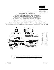
MECHANICAL FEATURES:<br />
TYPE I CONFIGURATION:<br />
<strong>The</strong> Type I pushbutton switch configuration provides low weight, minimum<br />
length and a variety of solder terminals.<br />
Packaging Dimensions: <strong>The</strong> Type I switch assembly physical dimensions and<br />
configuration conform to Figure 1. Dimensions are in inches. Tolerances are<br />
±0.03" for two place decimals and ±0.010” for three place decimals.<br />
Lowest Weight: 19 grams (0.67 ounces) maximum including mounting sleeve<br />
and mounting spacer.<br />
Minimum Length: Overall length is 1.310" less terminals. <strong>The</strong> behind panel<br />
depth is 1.093" maximum excluding terminals. See Figure 1 for length of<br />
terminals.<br />
Enclosure Design: Unsealed.<br />
Housing Material and Finish: Aluminum, black anodized.<br />
Solder Terminations: <strong>The</strong> Type 1 configuration is available in three solder<br />
terminal styles: turret terminals, spade terminals or wire wrap/pcb terminals.<br />
TYPE III CONFIGURATION:<br />
<strong>The</strong> Type III pushbutton switch assembly is comprised of a pushbutton lens cap,<br />
a switch body having one or two switch poles (single or double break), a panel<br />
mounting spacer and a reversible mounting sleeve.<strong>The</strong> switch body accepts an<br />
easy to install 2 Pole QUIK-CONNECT plug which is designed as a solderless<br />
common termination system (CTS).<br />
Packaging Dimensions: <strong>The</strong> Type III switch assembly physical dimensions<br />
and configuration conform to Figure 2. Dimensions are in inches. Tolerances<br />
are ±0.03" for two place decimals and ±0.010” for three place decimals.<br />
Low Unit Weight: 26 grams (0.92 ounces) maximum including mounting sleeve<br />
and spacer, less connector plug.<br />
2 Pole QUIK-CONNECT Plug Weight: 6 grams (0.21 ounces) maximum.<br />
Length: Overall length is 2.00" including connector. <strong>The</strong> behind the panel depth<br />
is 1.78", the shortest available for any switch having a common termination<br />
system.<br />
2 Pole QUIK-CONNECT Plug: <strong>The</strong> 2 Pole QUIK-CONNECT plug is not<br />
supplied with the Type III pushbutton switch assembly. It is ordered separately<br />
as <strong>Aerospace</strong> <strong>Optics</strong> P/N 18-200 (includes <strong>Aerospace</strong> <strong>Optics</strong> P/N 18-215<br />
sealing plugs).<br />
Enclosure Design: Unsealed.<br />
Housing Material and Finish: Stainless steel.<br />
Wiring the QUIK-CONNECT Plug: <strong>The</strong> connector is wired like a common<br />
termination system but remains a removable connector.<br />
Solderless Termination: MIL-C-39029/22-192 sockets crimped onto 20, 22 or<br />
24 gauge wire without soldering.<br />
Loading Wires: Wires with the MIL-C-39029/22-192 sockets crimped on are<br />
inserted and extracted from the QUIK-CONNECT plug by use of a<br />
M81969/14-10 tool.<br />
Mating the QUIK-CONNECT Plug: No tool is necessary to plug the<br />
connector into the housing but an extraction tool, <strong>Aerospace</strong> <strong>Optics</strong> P/N 18-234,<br />
is required to unplug the connector.<br />
TYPE V CONFIGURATION:<br />
<strong>The</strong> Type V pushbutton switch assembly is comprised of a pushbutton lens cap,<br />
a switch body having four switch poles (single or double break), a panel<br />
mounting spacer and a reversible mounting sleeve.<strong>The</strong> switch body accepts an<br />
easy to install 4 Pole QUIK-CONNECT connector plug which is designed as<br />
a solderless common termination system (CTS).<br />
Packaging Dimensions: <strong>The</strong> Type V switch assembly physical dimensions<br />
and configuration conform to Figure 3. Dimensions are in inches. Tolerances<br />
are ±0.03" for two place decimals and ±0.010” for three place decimals.<br />
Low Unit Weight: 38 grams (1.34 ounces) maximum including mounting sleeve<br />
and spacer, less connector plug.<br />
4 Pole QUIK-CONNECT Plug Weight: 6 grams (0.21 ounces) maximum.<br />
Length: Overall length is 2.75" including connector. <strong>The</strong> behind the panel depth<br />
is 2.53" and is the shortest available for any 4 pole switch having a common termination<br />
system (CTS).<br />
4 Pole QUIK-CONNECT Plug: <strong>The</strong> 4 Pole QUIK-CONNECT plug is not<br />
supplied with the Type V pushbutton switch assembly. It is ordered separately<br />
as <strong>Aerospace</strong> <strong>Optics</strong> P/N 18-240 (Includes <strong>Aerospace</strong> <strong>Optics</strong> P/N 18-215<br />
sealing plugs).<br />
Enclosure Design: Unsealed.<br />
Housing Material and Finish: Stainless steel.<br />
Wiring the QUIK-CONNECT Plug: <strong>The</strong> connector is wired like a common<br />
termination system but remains a removable connector.<br />
Solderless Termination: MIL-C-39029/22-192 sockets crimped onto 20, 22 or<br />
24 gauge wire without soldering.<br />
Loading Wires: Wires with the MIL-C-39029/22-192 sockets crimped on are<br />
inserted and extracted from the QUIK-CONNECT plug by use of a<br />
M81969/14-10 tool.<br />
Mating the QUIK-CONNECT Plug: No tool is necessary to plug the<br />
connector into the housing but an extraction tool, <strong>Aerospace</strong> <strong>Optics</strong> P/N 18-234,<br />
is required to unplug the connector.<br />
FIGURE 1<br />
TYPE I UNSEA<strong>LED</strong> SWITCH DIMENSIONS<br />
FIGURE 2<br />
TYPE III UNSEA<strong>LED</strong> SWITCH DIMENSIONS<br />
<strong>Aerospace</strong> <strong>Optics</strong>, Inc. Data Sheet No. 12-2001-04 Rev. B 2002 <strong>Aerospace</strong> <strong>Optics</strong>, Inc. Page 7<br />
3201 Sandy Lane, Fort Worth, Texas, 76112 Tel:1-888-<strong>VIVISUN</strong> E-Mail:switches@vivisun.com Website:http://www.vivisun.com
<strong>VIVISUN</strong><br />
®<br />
L E D <strong>The</strong> <strong>Complete</strong> <strong>Switch</strong><br />
TYPE I, TYPE III AND TYPE V CONFIGURATIONS:<br />
<strong>The</strong> Type I, Type III and Type V pushbutton switch configurations offer several<br />
mechanical features common to these types.<br />
Mechanical Life: 100,000 cycles. Tested for 10,000 cycles at -40°C, 20,000<br />
cycles at +71°C and 70,000 cycles at +25°C.<br />
Pushbutton Action: Momentary, Alternate or Indicator (Indicators are only available<br />
in Type I, Type II, Type III or Type IV).<br />
Operating Characteristics:<br />
Actuation travel: 0.150" ±0.031".<br />
Actuation force: 2 to 5 pounds.<br />
Strength of Actuator: 25 pounds static load.<br />
Pushbutton Lens Cap: <strong>The</strong> pushbutton lens cap serves as the display module<br />
for the pushbutton switch assembly and is illuminated by non-replaceable <strong>LED</strong>s<br />
permanently mounted within the pushbutton cap. See Figure 4.<br />
Pushbutton Cap Extraction Force: 2 to 5 pounds.<br />
Keying: Pushbutton cap is designed to prevent incorrect insertion. See Figure 4.<br />
Pushbutton Cap Captivation: To prevent accidental interchange during mounting,<br />
the pushbutton caps are held captive to the switch housing by means of a<br />
metallic retainer which is permanently mounted in the switch housing. See<br />
Figure 4.<br />
Removal of Pushbutton Cap: Caps may be changed, if need be, by popping<br />
the cap pins out of the retaining element rails and replacing with another cap.<br />
Panel Mounting Spacer: A panel mounting spacer is supplied with each unit so<br />
as to place the switch mounting flange flush with a 0.235" thick edgelighted<br />
panel. For other switch applications the spacer is discarded.<br />
Mounting Sleeve: A reversible mounting sleeve is supplied with each unit so as<br />
to be usable with or without the panel mounting spacer.<br />
Mounting Plate Thickness: <strong>The</strong> mounting sleeve allows the switch to be<br />
installed on mounting plates ranging from 0.032" to 0.187" thick.<br />
Mounting Cutout Dimensions: See Figure 5.<br />
Front Mounting: <strong>The</strong> switch assembly is mounted from the front of the mounting<br />
plate by means of a screwdriver only. All mounting screws are integral to the<br />
switch.<br />
Mounting the <strong>Switch</strong>: Using the extraction slots, pull the pushbutton cap fully<br />
out of the switch body and allow the cap to rotate 90° where it is held by the<br />
retaining element as shown in Figure 4. Remove the mounting sleeve and insert<br />
the switch body into the mounting plate cutout. <strong>The</strong>n, from behind the mounting<br />
plate, slide the mounting sleeve onto the switch body. Tighten the two screws<br />
inside the switch body until the integral mounting hardware pulls the mounting<br />
sleeve up tight against the mounting plate using typically 18 inch-ounces of<br />
torque. <strong>The</strong> pushbutton cap is then reinserted and the QUIK-CONNECT$ plug<br />
can be plugged into the switch housing. A side view of a properly mounted switch<br />
is shown in Figure 1, Figure 2 and Figure 3.<br />
ENVIRONMENTAL CONDITIONS:<br />
Temperature: Operating: -40°C to +71°C<br />
Nonoperating: -40°C to +71°C<br />
<strong>The</strong>rmal Shock: In accordance with MIL-STD-202, method 107, test condition A,<br />
except -40°C to +71°C.<br />
Altitude: Sea level to 50,000 ft.<br />
Shock: In accordance with MIL-STD-202, method 213, test condition B, 75’Gs.<br />
Vibration: In accordance with MIL-STD-202, method 204, test condition B,<br />
(10-2,000Hz).<br />
Moisture Resistance: In accordance with MIL-STD-202, method 106 as<br />
modified by MIL-PRF-22885F.<br />
Fungus: In accordance with MIL-STD-454, requirement 4.<br />
Salt Spray: In accordance with MIL-STD-202, method 101, test condition A.<br />
Explosion: In accordance with MIL-STD-202, method 109.<br />
DO-160D ELECTRICAL ENVIRONMENTAL CONDITIONS:<br />
Magnetic Effect: In accordance with Section 15, equipment Class A.<br />
Power Input: In accordance with Section 16, Category Z (28VDC) Normal<br />
18VDC to 30.3VDC, Normal Surge 12VDC to 50VDC, Undervoltage 10VDC,<br />
Abnormal 20.5VDC to 32.2VDC and Abnormal Surge to 80VDC.<br />
Voltage Spike: In accordance with Section 17, Category A, 600 volt spikes.<br />
Audio Frequency Conducted Susceptibility: In accordance with Section 18,<br />
Category Z.<br />
Induced Signal Susceptibility: In accordance with Section 19, Categories C & Z.<br />
Radio Frequency Susceptibility (Radiated and Conducted): In accordance<br />
with Section 20, Category R, high energy radiated fields (HERF) conducted susceptibility<br />
20 V/m, 10 kHz to 400 MHz and radiated susceptibility 20 V/m, 0.1 GHz<br />
to 0.4 GHz and 150 V/m (Pulse) 0.4 GHz to 8 GHz.<br />
Emission of Radio Frequency Energy: In accordance with Section 21,<br />
Category M conducted RF interference 150 kHz to 30 MHz and radiated RF interference,<br />
2 MHz to 6 GHz.<br />
Lightning Induced Transient Susceptibility: In accordance with Section 22,<br />
Category A3XX, waveform 3, 600V/24A and waveform 4, 300V/60A.<br />
Electrostatic Discharge (ESD): Immune to electrostatic discharge, withstanding<br />
the 15,000 volt pulse requirements of Section 25 for Category A equipment.<br />
FIGURE 3<br />
TYPE V FOUR POLE UNSEA<strong>LED</strong> SWITCH DIMENSIONS<br />
FIGURE 4<br />
UNSEA<strong>LED</strong> SWITCH PUSHBUTTON LENS CAP AND RETAINER<br />
FIGURE 5<br />
MOUNTING PLATE CUTOUT DIMENSIONS<br />
TYPE I, TYPE III AND TYPE V UNSEA<strong>LED</strong> SWITCHES<br />
<strong>Aerospace</strong> <strong>Optics</strong>, Inc. Data Sheet No. 12-2001-04 Rev. B 2002 <strong>Aerospace</strong> <strong>Optics</strong>, Inc. Page 8<br />
3201 Sandy Lane, Fort Worth, Texas, 76112 Tel:1-888-<strong>VIVISUN</strong> E-Mail:switches@vivisun.com Website:http://www.vivisun.com
<strong>VIVISUN</strong><br />
®<br />
L E D <strong>The</strong> <strong>Complete</strong> <strong>Switch</strong><br />
DRIPPROOF, WATERTIGHT, SPLASHPROOF SEA<strong>LED</strong> SWITCHES:<br />
Type II Configuration: <strong>The</strong> Type II switch assembly is a sealed pushbutton<br />
switch comprised of a Type I switch body, a sealed pushbutton cap, a seal<br />
mounting flange with attatched gasket, a panel mounting spacer with attached<br />
gasket and a reversible mounting sleeve.<br />
Type IV Configuration: <strong>The</strong> Type IV switch assembly is a sealed pushbutton<br />
switch comprised of a Type III switch body, a sealed pushbutton cap, a seal<br />
mounting flange with attached gasket, a panel mounting spacer with attached<br />
gasket and a reversible mounting sleeve.<br />
Type VI Configuration: <strong>The</strong> Type VI switch assembly is a sealed pushbutton<br />
switch comprised of a Type V switch body, a sealed pushbutton cap, a seal<br />
mounting flange with attached gasket, a panel mounting spacer with attached<br />
gasket and a reversible mounting sleeve.<br />
Packaging Dimensions: <strong>The</strong> Type II, Type IV and Type VI switch assembly<br />
dimensions and configurations conform to Figure 6. Dimensions are in inches.<br />
Tolerances are ±0.03" for two place decimals and ±0.010” for three place decimals.<br />
Low Unit Weight: 21 grams (0.75 ounces) maximum for Type II, 28 grams (0.99<br />
ounces) maximum for Type IV and 41 grams (1.45 ounces) maximum for Type<br />
VI including mounting flange, panel spacer and mounting sleeve, less<br />
connector plug.<br />
Panel Mounting Spacer: A panel spacer is supplied and is used only when<br />
mounting through an edgelighted panel, otherwise discard.<br />
Mounting Flange and Spacer Material: <strong>The</strong>moplastic, UL-94-VO matte black<br />
finish and silicone rubber per ZZ-R-765 for the attached gasket.<br />
Sealed Pushbutton Caps: <strong>The</strong> pushbutton caps are supplied with an integral<br />
rubber seal which is permanently attached to the cap. See Figure 6.<br />
Seal Material: <strong>The</strong> seal material is silicone rubber per ZZ-R-765. <strong>The</strong> surface<br />
has a matte black finish.<br />
Mounting Cutout Dimensions: See Figure 6.<br />
Installing Sealed Pushbutton Caps: After the switch assembly is properly<br />
mounted, the sealed pushbutton cap is installed by first pushing the cap all the<br />
way down to its fully retained position. To seal the cap onto the seal mounting<br />
flange, press a lower corner of the seal into the lower flange corner using firm<br />
finger pressure. Next, press each of the remaining corners of the seal into their<br />
respective flange corners. Follow by pressing each of the four sides into the seal<br />
mounting flange. <strong>The</strong> seal is then secured into the mounting flange by firmly<br />
pressing all previously pressed areas and smoothing any bulges by additional<br />
pressure.This will insure proper seal to mounting flange integrity.<br />
Enclosure Design: When properly installed, the sealing will meet the<br />
requirements for dripproof, watertight and splashproof sealed enclosure<br />
designs.<br />
Dripproof Sealing: <strong>The</strong> sealed switches do not allow any leakage of water<br />
though the seal when subjected to the dripproof sealing test defined in<br />
MIL-PRF-22885F, paragraph 4.7.20.3 and MIL-STD-108.<br />
Watertight Sealing: <strong>The</strong> sealed switches do not allow any leakage of water<br />
through the seal when subjected to the watertight sealing test defined in<br />
MIL-PRF-22885F, paragraph 4.7.20.2 and MIL-STD-108.<br />
Splashproof Sealing: <strong>The</strong> sealed switches do not allow any leakage of water<br />
through the seal when subjected to the splashproof sealing test defined in<br />
MIL-PRF-22885F, paragraph 4.7.20.1 and MIL-STD-108.<br />
Sand and Dust: <strong>The</strong> sealed switches meet the sand and dust sealing test<br />
defined in MIL-PRF-22885F, paragraph 4.7.26.<br />
High Impact Shock: When specified, the sealed indicators and momentary<br />
action sealed switches meet the high impact shock test defined in<br />
MIL-PRF-22885F, paragraph 4.7.16.2 Method II.<br />
ELECTRICAL FEATURES:<br />
Electrical Life: 50,000 cycles minimum at rated loads at +71°C ambient<br />
temperature.<br />
<strong>Switch</strong> Contacts: Available in silver with gold flash or gold plate.<br />
<strong>Switch</strong> Contact Ratings:<br />
SILVER CONTACTS WITH GOLD FLASH<br />
Load Single break Double Break<br />
28VDC @ sea level Resistive 7.5 amp 4.0 amps<br />
Inductive 4.0 amp 2.0 amps<br />
Motor 4.0 amps -<br />
Lamp 1.0 amps -<br />
28VDC @ 50,000 ft. Resistive 4.0 amp 3.0 amps<br />
Inductive 2.5 amps 1.0 amps<br />
115VAC, 60 HZ. @ sea level Resistive 7.5 amps -<br />
Inductive 4.0 amps -<br />
GOLD PLATED CONTACTS<br />
Load Single Break Double Break<br />
28VDC @ sea level Resisitive 1.0 amps -<br />
Inductive 0.5 amps -<br />
28VDC @ 50,000 ft. Resistive 1.0 amps -<br />
Inductive 0.5 amps -<br />
<strong>Switch</strong> Type: <strong>The</strong> basic snap action switches are qualified to MIL-PRF-8805/101<br />
catergory I or category II.<br />
<strong>Switch</strong> Capacity: Single pole double throw, double pole double throw or four<br />
pole double throw.<br />
<strong>Switch</strong> Contact Schematic:<strong>The</strong> switch contact arrangements are either single<br />
break or double break. <strong>The</strong> double break allows two separate contact circuits or<br />
simply a single throw contact action. See Figure 7.<br />
FIGURE 6<br />
TYPE II, TYPE IV AND TYPE VI SEA<strong>LED</strong> SWITCH DIMENSIONS<br />
FIGURE 7<br />
SWITCH CONTACT IDENTIFICATION AND CIRCUIT SCHEMATIC<br />
<strong>Aerospace</strong> <strong>Optics</strong>, Inc. Data Sheet No. 12-2001-04 Rev. B 2002 <strong>Aerospace</strong> <strong>Optics</strong>, Inc. Page 9<br />
3201 Sandy Lane, Fort Worth, Texas, 76112 Tel:1-888-<strong>VIVISUN</strong> E-Mail:switches@vivisun.com Website:http://www.vivisun.com
<strong>VIVISUN</strong><br />
®<br />
L E D <strong>The</strong> <strong>Complete</strong> <strong>Switch</strong><br />
<strong>Switch</strong> Contact Resistance: 0.025 ohms maximum for silver with gold flash contacts.<br />
Intermediate Current: <strong>The</strong> intermediate current test per MIL-PRF-22885F paragraph<br />
3.35 is applicable to the gold flash silver contacts. 50,000 cycles minimum,<br />
12,500 cycles at -40°C, 25,000 cycles at +23°C and 12,500 cycles at +71°C.<br />
Low Level Life: <strong>The</strong> low level life test per MIL-PRF-22885F paragraph 3.36 is<br />
applicable to the gold plated contacts. 50,000 cycles with contacts loaded at 30<br />
millivolts maximum DC or peak AC at 10 milliamperes maximum. 12,500 cycles at<br />
-40°C, 12,500 cycles at +23°C and 25,000 cycles at +71°C.<br />
Dielectric Withstanding Voltage:<br />
At sea level: 1000 volts rms minimum, 60 Hz.<br />
At 50,000 ft.: 400 volts rms minimum, 60 Hz.<br />
Pushbutton Cap Display Styles: <strong>The</strong> pushbutton cap display is available in five<br />
versions, a four way split screen, a horizontal split screen, two three way split<br />
screens and a full screen display. See Figure 8.<br />
<strong>LED</strong> Circuit Configurations: Each pushbutton cap contains 16 <strong>LED</strong>s, 4 per<br />
quadrant, and all the electronics necessary for display illumination. <strong>The</strong> <strong>LED</strong> circuit<br />
is either a single circuit with one common, G (Style 1) or it is a horizontal split<br />
circuit with two commons, G and F (Style 2). Each quadrant has its own I/O labeled<br />
A, B, C, and D according to the quadrant it illuminates. Each quadrant has its own<br />
independent electronic circuit consisting of 4 <strong>LED</strong>s and the Driver, Dimming and<br />
Protection Circuit (DDPC) needed for their operation. <strong>The</strong> <strong>LED</strong> circuit can be either<br />
28 VDC common anode (current sinking) or 28 VDC common cathode (current<br />
sourcing). Polarity is referenced with respect to commons G and F. See Figure 9.<br />
Quadrant Interconnection Circuit Styles: To reduce the number of input wires<br />
necessary to illuminate the display, the pushbutton cap is available with the quadrants<br />
A, B, C and D internally connected in various circuit styles so one input wire<br />
can activate one or more quadrants as shown in Figure 10.<br />
<strong>Switch</strong> and <strong>LED</strong> Terminal Identification: <strong>The</strong> switch poles are denoted as posi -<br />
tion A for the single pole version, A and B for the two pole version and H, J, K and<br />
L for the four pole version. <strong>Switch</strong> contact terminals are marked 1, 2, 3 and 4. <strong>LED</strong><br />
terminals are marked A, B, C, D, F and G. See Figure 11.<br />
Power Consumption: <strong>The</strong> typical power consumption of the <strong>LED</strong> illuminated<br />
pushbutton cap at 23°C is 1.18 watts for 28 VDC units.<br />
EMI/RFI Shielding Option: When specified, the shielding efficiency of the pushbutton<br />
switch is no less than 60dB for frequencies from 100MHz to 1000MHz.<br />
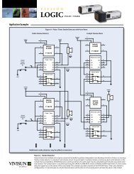
FIGURE 10<br />
PUSHBUTTON CAP QUADRANT INTERCONNECTION CIRCUIT STYLES<br />
FIGURE 8<br />
PUSHBUTTON CAP DISPLAY STYLES<br />
FIGURE 11<br />
SWITCH BODY AND <strong>LED</strong> TERMINAL IDENTIFICATION (BACK VIEW)<br />
FIGURE 9<br />
PUSHBUTTON CAP <strong>LED</strong> CIRCUIT DIAGRAMS, VOLTAGE AND POLARITY<br />
Diagrams are as viewed from the front of the display.<br />
1. A and B identify the switch pole positions for the one pole and two pole versions and<br />
H, J, K and L identify the switch pole positions for the four pole version.<br />
2. <strong>The</strong> switch contact terminals are identified as 1, 2, 3 and 4.<br />
3. A, B, C and D identify the <strong>LED</strong> quadrant inputs and G and F identify the commons.<br />
4. “SKT” identifies the socket side where input wires are inserted.<br />
5. All solderless CTS QUIK-CONNECT plugs are supplied with sealing plugs P/N 18-215<br />
or MS27488-20 which must be inserted into the unused locations. Example: A 4 pole,<br />
single break, single circuit pushbutton switch utilizing only 3 poles will require 8 sealing<br />
plugs (see example above), 1 each in location 1, 2, 3 and 4 of the unused switch pole<br />
L,1each in location 4 of the 3 active poles H, J and K and in location F of the <strong>LED</strong> circuit.<br />
<strong>Aerospace</strong> <strong>Optics</strong>, Inc. Data Sheet No. 12-2001-04 Rev. B 2002 <strong>Aerospace</strong> <strong>Optics</strong>, Inc. Page 10<br />
3201 Sandy Lane, Fort Worth, Texas, 76112 Tel:1-888-<strong>VIVISUN</strong> E-Mail:switches@vivisun.com Website:http://www.vivisun.com
<strong>VIVISUN</strong><br />
®<br />
<strong>LED</strong> <strong>The</strong> <strong>Complete</strong> <strong>Switch</strong><br />
VISUAL FEATURES:<br />
DISPLAY CHARACTERISTICS:<br />
Display Illumination: <strong>The</strong> <strong>VIVISUN</strong> <strong>LED</strong> display legends are illuminated by<br />
solid state, <strong>LED</strong> ( Light Emitting Diode) technology. <strong>The</strong> <strong>LED</strong>s are arranged in a<br />
matrix array of 16 <strong>LED</strong>s with 4 <strong>LED</strong>s per quadrant for high reliability and exceptional<br />
luminance uniformity.<br />
Chrominance and Luminance: <strong>The</strong> display legends are available in five standard<br />
colors whose chromaticity limits are shown in Figure 12. Typical 1931 CIE<br />
chromaticity coordinates and luminance values at full rated voltage are:<br />
Chromaticity<br />
Luminance<br />
Color x y Foot-Lamberts<br />
Blue<br />
Green<br />
0.143<br />
0.321<br />
0.178<br />
0.659<br />
300<br />
400<br />
White 0.349 0.356 450<br />
Yellow<br />
Red<br />
0.586<br />
0.680<br />
0.413<br />
0.317<br />
400<br />
300<br />
Four Separate Message Capability: Since each quadrant can be controlled<br />
individually a single pushbutton cap can display up to four separate messages,<br />
all in different colors.<br />
Viewing Angle: <strong>The</strong> standard color displays have a wide viewing angle of 60°<br />
to the normal of the display viewing surface (120° included angle) in sunlight and<br />
30° included angle in glare producing angles of direct sunlight conditions.<br />
Uniformity: <strong>The</strong> average character to character uniformity is 2:1 at 28VDC.<br />
Uniformity Color to Color: <strong>The</strong> average luminance uniformity from color to<br />
color is 3:1 and is maintained when dimmed to 14VDC using voltage dimming.<br />
NVIS COMPATIBILITY:<br />
NVIS Compliant: When specified, the <strong>VIVISUN</strong> <strong>LED</strong> display lighting is compatible<br />
with NVIS (Night Vision Imaging System) goggles and complies with the<br />
NVIS color and NVIS radiance requirements defined in MIL-L-85762A as referenced<br />
in JSSG-2010-5 and ASC/ENFC 96-01 and defined in MIL-STD-3009.<br />
NVIS Colors: <strong>The</strong> NVIS compliant lighting is available in six colors; NVIS blue, NVIS<br />
green A, NVIS green B, NVIS white, NVIS yellow and NVIS red. <strong>The</strong> NVIS blue,<br />
NVIS green A and NVIS white display chromaticity coordinates are within the areas<br />
bounded by a circle for blue, green A and white and a circle and the spectrum locus<br />
for green B as shown in Figure 13 when set to 0.1 foot-lamberts. <strong>The</strong> NVIS yellow<br />
and NVIS red display chromaticity coordinates are within the area bounded by a circle<br />
and the spectrum locus as shown in Figure 13 when set to 15.0 foot-lamberts.<br />
Chromaticity Coordinates: Typical 1976 CIE UCS chromaticity coordinates<br />
when set to the stated luminance levels are:<br />
Color<br />
Chromaticity<br />
u′ v′<br />
Luminance<br />
Foot-Lamberts<br />
NVIS Blue<br />
NVIS Green A<br />
0.087<br />
0.089<br />
0.384<br />
0.555<br />
@<br />
@<br />
0.1<br />
0.1<br />
NVIS Green B 0.130 0.578 @ 0.1<br />
NVIS White<br />
NVIS Yellow Class A<br />
0.184<br />
0.221<br />
0.486<br />
0.566<br />
@ 0.1<br />
@ 15.0<br />
NVIS Yellow Class B 0.262 0.560 @ 15.0<br />
NVIS Red 0.405 0.539 @ 15.0<br />
NVIS Response Curves: <strong>The</strong>re are two NVIS response curves. <strong>The</strong> Class A<br />
uses a 625 nm minus blue filter which does not allow any red cockpit lighting.<br />
<strong>The</strong> Class B which uses a 665 nm minus blue filter which does allow the use of<br />
properly designed NVIS red lighting. Figure 14 shows the Class A and Class B<br />
relative response curves as compared to the photopic relative response curve.<br />
NVIS Radiance: <strong>The</strong> NVIS compliant lighting meets the following MIL-L-85762A<br />
NVIS radiance requirements when set to the stated luminance levels.<br />
Color<br />
NVIS Radiance<br />
Maximum Minimum<br />
NVIS<br />
Type / Class<br />
Luminance<br />
Foot-Lamberts<br />
NVIS Blue
<strong>VIVISUN</strong><br />
®<br />
L E D <strong>The</strong> <strong>Complete</strong> <strong>Switch</strong><br />
VISIBLE LEGEND DISPLAYS:<br />
Visible White Legends: <strong>The</strong> <strong>VIVISUN</strong> <strong>LED</strong> displays are available with translucent<br />
visible white legends with illuminating characters on an opaque black background.<br />
Display Type N, Luminance and Color: <strong>The</strong> Type N displays per MIL-PRF-<br />
22885F have visible white legends that are reflective white and are always visible<br />
in any ambient light except darkened conditions. When the ambient is<br />
reduced to darkened conditions the visible white legends can be energized and<br />
produce an average luminance between 0.5 and 3.0 foot-lamberts at rated voltage.<br />
This type of display is available with legends illuminated in one of five colors:<br />
white, red, NVIS green A, NVIS green B or NVIS white.<br />
Display Type D, Luminance and Color: <strong>The</strong> Type D displays have white,<br />
always visible legends that can be energized to produce an average luminance<br />
in excess of 100 foot-lamberts at rated voltage. This type of display is typically<br />
used in shipboard applications and is only available in the standard colors blue,<br />
green, white, yellow or red.<br />
BACKGROUND ILLUMINATING DISPLAYS:<br />
Background Illumination: <strong>The</strong> <strong>VIVISUN</strong> <strong>LED</strong> displays are available with background<br />
illuminating legends wherein the legends do not light but the backgrounds<br />
surrounding the legends light up when the display is eneregized.<br />
Display Type B, Luminance and Color: <strong>The</strong> Type B displays per MIL-PRF-<br />
22885F are hidden legend having black legends on an obscure black background.<br />
When illuminated the legend appears black and the background appears<br />
in color.<strong>The</strong> display is readable in daylight and does not appear energized in the<br />
unlighted mode. Although the contrast requirements do not apply the average<br />
luminance exceeds 200 foot-lamberts. <strong>The</strong>se displays are typically used as red<br />
colored warning signals as defined in MIL-STD-411F; however, they are available<br />
in any of the colors referenced in Figure 17 for special applications.<br />
Display Type A, Luminance and Color: <strong>The</strong> Type A displays have reflective<br />
white, always visible legends on an obscure black background. When illuminated<br />
the background appears in color and is discernible in daylight and does not<br />
appear energized in the unlighted mode. <strong>The</strong> average luminance exceeds 200<br />
foot-lamberts at rated voltage, however the contrast requirements are not applicable.<br />
<strong>The</strong>se displays are used in special applications and are available with<br />
background lighting in any of the colors referenced in Figure 17.<br />
Display Type W, Luminance and Color: <strong>The</strong> Type W displays have visible<br />
black legends on a white translucent background. When illuminated the legend<br />
remains black and the background illuminates in color. <strong>The</strong> average luminance<br />
of the background exceeds 100 foot-lamberts at rated voltage and the lighting is<br />
only available in the standard colors blue, green, white, yellow or red.<br />
LETTERING STYLES AND CHARACTER SIZES:<br />
Display Type S, Type B and Type W: <strong>The</strong> Type S, B and W legends are Globe<br />
Condensed capitals for character sizes of 0.156”, 0.125” and 0.109” in height and<br />
Alternate Gothic Condensed capitals for characters 0.072” and 0.090” in height.<br />
Custom symbols are also available.<br />
Display Type N, Type A and Type D: <strong>The</strong> Type N, A and D legends are Futura<br />
Medium Condensed capitals for character sizes of 0.156”, 0.125” and 0.109” in<br />
height and Alternate Gothic Condensed capitals for characters 0.072” and 0.090”<br />
in height. Custom symbols are also available.<br />
VOLTAGE DIMMING CHARACTERISTICS:<br />
Voltage Dimming: Dimming the Type S <strong>VIVISUN</strong> <strong>LED</strong> displays from daylight<br />
brightness at full rated voltage to night flying brightness is accomplished by simply<br />
reducing the applied voltage until the desired low level luminance is achieved.<br />
Standard Dimming : All Type S colors have a uniform dimming range from 16<br />
volts down to 10 volts as shown in Figure 18. <strong>The</strong> average display brightness for<br />
all colors is 20 ± 10 foot-lamberts at 14 VDC for the 28 VDC <strong>LED</strong> circuits as<br />
measured at 23°C.<br />
Low Level Dimming: <strong>The</strong> Type S colors of blue, green, white and yellow used<br />
for caution and advisory signals can be dimmed to 1.0 foot-lamberts (red warning<br />
signals must remain at 15.0 foot-lamberts) as required by MIL-STD-411F for<br />
non-NVIS military aircrew stations. <strong>The</strong> average display luminance is 0.5 to 3.0<br />
foot-lamberts at 7.2 VDC for the 28 VDC <strong>LED</strong> circuits as measured at 23°C.<br />
Figure 19 shows the dimming range.<br />
NVIS Compatible Dimming: <strong>The</strong> Type S NVIS blue, NVIS green A, NVIS green<br />
B, NVIS white and NVIS yellow colors can be dimmed to 0.1 foot-lamberts as<br />
required by MIL-L-85762A and MIL-STD-411F for NVIS compatible military aircrew<br />
stations. <strong>The</strong> average display luminance is 0.05 to 0.3 foot-lamberts at 6.55<br />
volts for the 28 VDC <strong>LED</strong> circuits as measured at 23°C. Figure 20 shows the dimming<br />
range.<br />
Minimum Luminance Current: <strong>The</strong> 28 VDC <strong>LED</strong> displays require approximately<br />
1 milliamp of current per quadrant before producing a perceptible level of<br />
luminance so the <strong>LED</strong>s will not light inadvertently due to microamp currents.<br />
Emergency Power Operation: <strong>The</strong> Type S displays are easily readable in<br />
emergency power conditions of 18 VDC producing in excess of 50 foot-lamberts<br />
at 18 VDC.<br />
RELIABILITY:<br />
Mean Time To Failure: <strong>The</strong> <strong>VIVISUN</strong> <strong>LED</strong> MTTF for the 28 VDC lighted<br />
pushbutton cap is in excess of 125,000 hours as calculated per MIL-HDBK-217F,<br />
Notice 2 for an AIF (Airborn Inhabited Fighter) environment at 60°C.<br />
No Maintenance: <strong>The</strong> high reliability design enables the <strong>VIVISUN</strong> <strong>LED</strong> to operate<br />
virtually maintenance free for the life of the avionics platform.<br />
No Catastrophic Failure Modes: Since each quadrant has its own electronics<br />
circuit independent of the other quadrants, any failure would result in the loss of<br />
that quadrant only while the other three quadrants would continue to function.<br />
FIGURE 16<br />
NORMALIZED SPECTRAL RADIANCE FOR TYPE I CLASS B NVIS COLORS<br />
FIGURE 17<br />
MINIMUM CONTRAST FOR SUNLIGHT READABLE DISPLAYS (TYPE S)<br />
1/ Minimum and typical average display luminance at full rated voltage, 28 VDC.<br />
FIGURE 18<br />
TYPICAL VOLTAGE DIMMING RANGE AT 23°C FOR TYPE S DISPLAYS<br />
FIGURE 19<br />
TYPICAL NON-NVIS MILITARY DIMMING RANGE AT 23°C (TYPE S)<br />
FIGURE 20<br />
TYPICAL NVIS COMPATIBLE DIMMING RANGE AT 23°C (TYPE S)<br />
nm<br />
<strong>Aerospace</strong> <strong>Optics</strong>, Inc. Data Sheet No. 12-2001-04 Rev. B 2002 <strong>Aerospace</strong> <strong>Optics</strong>, Inc. Page 12<br />
3201 Sandy Lane, Fort Worth, Texas, 76112 Tel:1-888-<strong>VIVISUN</strong> E-Mail:switches@vivisun.com Website:http://www.vivisun.com
<strong>VIVISUN</strong><br />
®<br />
L E D <strong>The</strong> <strong>Complete</strong> <strong>Switch</strong><br />
HOW TO ORDER<br />
<strong>VIVISUN</strong> <strong>LED</strong> SWITCHES<br />
Line 1<br />
<strong>The</strong> <strong>VIVISUN</strong> <strong>LED</strong> pushbutton switches and indicators are ordered by specifying a<br />
basic 14 character part number shown on Line 1 which is comprised of (a) 3 letters<br />
to define the <strong>Aerospace</strong> <strong>Optics</strong> <strong>VIVISUN</strong> <strong>LED</strong> product line, (b) 2 characters to define<br />
the switch body type, (c) 2 digits to define features that apply to both the switch body<br />
and pushbutton cap, (d) 2 characters to define the pushbutton cap, and (e) 5 digit<br />
artwork part number. Line 2 is provided to define the exact artwork used in the cap.<br />
NOTE: A 5 digit artwork part number is assigned by <strong>Aerospace</strong> <strong>Optics</strong> to abbreviate<br />
and designate customer legend and color information specified on Line 2.<br />
Line 2<br />
Line 2 provides the detailed artwork description of the legend position and type of lighting, color, character height and specific legends to be displayed within<br />
that legend position. When two or more legend positions (see Table 6) are to display legend information, a semicolon separates the legend information for<br />
each position. When two or more lines of characters (see Table 9) are to be used in one legend position the individual lines are separated by a comma.<br />
To specify a <strong>VIVISUN</strong> <strong>LED</strong> pushbutton switch or indicator, determine the Line 1 basic part number as follows:<br />
Step 1: Select the desired type of switch termination from Table 1. Insert the<br />
appropriate designation number into the fourth position of the basic 14 character<br />
part number.<br />
Step 2: Select the desired switch poles and contact material from Table 2 and<br />
insert the appropriate designation number or letter into the fifth position of the<br />
basic 14 character part number.<br />
Step 3: Select the desired enclosure design and EMI shielding option as listed<br />
in Table 3 and insert the appropriate designation number into the sixth position<br />
of the basic 14 character part number.<br />
Step 4: Select the pushbutton actuation and <strong>LED</strong> circuit configuration from<br />
Table 4 and insert the appropriate actuation designation number into the seventh<br />
position of the basic 14 character part number.<br />
TABLE 1<br />
Terminations<br />
TABLE 2<br />
<strong>Switch</strong> Poles<br />
and Contact<br />
Material<br />
TABLE 3<br />
Enclosure Design<br />
and EMI<br />
Termination Type<br />
Solder Terminals<br />
Turret<br />
Spade<br />
Wire wrap<br />
Solderless QUIK-CONNECT<br />
Common Termination System<br />
(CTS)<br />
Solderless QUIK-CONNECT<br />
Common Termination System<br />
(CTS)<br />
<strong>Switch</strong> Poles<br />
1 and 2 Pole or Indicator<br />
1 and 2 Pole or Indicator<br />
1 and 2 Pole or Indicator<br />
1 and 2 Pole or Indicator<br />
4 Pole Only<br />
<strong>Switch</strong><br />
Poles<br />
SPDT-SB<br />
DPDT-SB<br />
SPDT-DB<br />
DPDT-DB<br />
4PDT-SB (Type V & VI)<br />
4PDT-DB (Type V & VI)<br />
Indicator (Type I, II, III, & IV Only)<br />
1 - Unsealed<br />
2 - Dripproof/Watertight/Splashproof<br />
3 - Dripproof, etc. with High Impact Shock<br />
Step 5: Select the desired pushbutton cap display style from Table 5 and<br />
insert this letter into the eighth position of the 14 character part number.<br />
Step 6: Select the <strong>LED</strong> voltage, circuit polarity and quadrant interconnection<br />
style designation letter from Table 7 and insert this letter into the ninth<br />
position of the part number.<br />
Step 7: <strong>Complete</strong> the Line 2 part number by using Tables 6, 8, 9 and the<br />
order example page.<br />
<strong>The</strong> bottom of each pushbutton cap is marked with the applicable<br />
quadrant activation circuit diagram from Table 10 and illustrated on the part<br />
number example page under the heading Pushbutton Cap Part Marking.<br />
<strong>The</strong> diagram shows the internal circuit configuration (single circuit or horizontal<br />
split circuit), the voltage, the circuit polarity and the inputs necessary<br />
to energize the <strong>LED</strong>s in each quadrant.<br />
Type<br />
I & II<br />
I & II<br />
I & II<br />
III & IV<br />
V & VI<br />
Designation Note: <strong>The</strong> solderless QUIK-CONNECT (CTS)<br />
designation number 4 is used to order a single<br />
1 pole or a 2 pole switch or indicator body portion<br />
2 only. <strong>The</strong> number 6 is used to order a 4 pole<br />
3 switch body portion only. <strong>The</strong> QUIK-CONNECT<br />
plug is ordered separately for convenience to permit<br />
wire harness manufacture without the necessi-<br />
4<br />
ty of having the switch/indicator body. <strong>The</strong> QUIK-<br />
6 CONNECT plug is ordered as P/N 18-200 for 1<br />
or 2 pole switches or indicators and P/N 18-240<br />
for 4 pole switches.<br />
Contact Material<br />
Silver Gold Plate<br />
1 5<br />
2 6<br />
3 7<br />
4 8<br />
A<br />
F<br />
C<br />
H<br />
0<br />
4 - Unsealed with EMI Shielding per MIL-PRF-22885F<br />
5 - Dripproof/Watertight/Splashproof with EMI Shielding per MIL-PRF-22885F<br />
6 - Dripproof, etc. with High Impact Shock and EMI Shielding per MIL-PRF-22885F<br />
TABLE 4<br />
Pushbutton<br />
Actuation<br />
and <strong>LED</strong> Circuit<br />
Configuration<br />
TABLE 5<br />
Pushbutton Cap<br />
Display Styles<br />
<strong>LED</strong> Circuit Configuration<br />
Style Description Block Diagram<br />
1 Single Circuit, One Common<br />
2 Horizontal Split Circuit, Two Commons<br />
Standard Designation<br />
NVIS Designation<br />
Actuation Designation<br />
Momentary Alternate * Indicator<br />
1 4 7<br />
2 5 8<br />
* High Impact Shock is not avaiable in Alternate Action<br />
<strong>Aerospace</strong> <strong>Optics</strong>, Inc. Data Sheet No. 12-2001-04 Rev. B 2002 <strong>Aerospace</strong> <strong>Optics</strong>, Inc. Page 13<br />
3201 Sandy Lane, Fort Worth, Texas, 76112 Tel:1-888-<strong>VIVISUN</strong> E-Mail:switches@vivisun.com Website:http://www.vivisun.com
<strong>VIVISUN</strong><br />
®<br />
<strong>LED</strong> <strong>The</strong> <strong>Complete</strong> <strong>Switch</strong><br />
TABLE 6<br />
Legend Positions<br />
and Display Type<br />
Lighting<br />
Display Type S: Sunlight readable legends on an opaque black background that are<br />
indiscernable until illuminated. When illuminated the legends appear in color.<br />
Display Type N: Visible white legends on an opaque black background. When illuminated<br />
the legends produce 0.5 to 3.0 foot-lamberts at rated voltage.<br />
Display Type B: Black legends on an obscure black background. When illuminated the<br />
legend remains black and the background appears in color.<br />
Display Type A: Always visible white legends on an obscure black background. When<br />
illuminated the background appears in color.<br />
Display Type D: Visible white legends on an opaque black background. When illuminated<br />
the legends light in color producing over 100 foot-lamberts at rated voltage.<br />
Type D displays are only available in blue, green, white, yellow or red.<br />
Display Type W: White background with visible black legends. When<br />
illuminated the legend remains black and the background appears in<br />
color producing over 100 foot-lamberts at rated voltage. Available<br />
only in Table 5 cap styles H and B wherein both B style positions<br />
must be Type W and in the colors blue, green, white, yellow or red only.<br />
Number Of Input<br />
Voltage, Cicuit Polarity and Designation Code<br />
Wires Excluding Quadrant Interconnections 28 VDC 28 VDC<br />
Commons G & F Block Diagram Description Common Anode Common Cathode<br />
Four inputs, all four<br />
quadrants independent<br />
A<br />
F<br />
TABLE 7<br />
<strong>LED</strong> Voltage,<br />
Circuit Polarity<br />
and Quadrant<br />
Interconnection<br />
Style<br />
Two inputs, top quadrants<br />
coupled and bottom<br />
quadrants coupled<br />
Three inputs, only bottom<br />
two quadrants coupled<br />
Three inputs, only top<br />
two quadrants coupled<br />
B<br />
C<br />
D<br />
G<br />
H<br />
J<br />
TABLE 8<br />
Color<br />
TABLE 9<br />
Character Capacity<br />
per Legend Position<br />
T - Blue<br />
G- Green<br />
A - White (Illuminant B, 4780°K)<br />
Y - Yellow<br />
R - Red<br />
Q-NVIS White<br />
One input, all four quadrants<br />
connected<br />
Character Character Lines Legend Position per Table 6<br />
Size Height Characters 1- A-K 2- 3- B-C-L 4-5-6 -7-D-E-F-G<br />
Q-W M-J-S-I-O N-P- R-T-U -V-X-Y<br />
1 1<br />
2 1<br />
3<br />
4<br />
A<br />
.125"<br />
.109"<br />
.072"<br />
.156"<br />
.090”<br />
Lines Per Position<br />
Characters Per Line<br />
Lines Per Position<br />
Characters Per Line<br />
Lines Per Position<br />
Characters Per Line<br />
Lines Per Position<br />
Characters Per Line<br />
Lines Per Position<br />
Characters Per Line<br />
Custom Symbols<br />
E - NVIS Blue<br />
H - NVIS Green A<br />
J - NVIS Green B<br />
K - NVIS Yellow Class A<br />
U - NVIS Yellow Class B<br />
S - NVIS Red<br />
3 1<br />
6 61728<br />
3<br />
7<br />
5 2<br />
8 3<br />
3<br />
2 1<br />
4 4<br />
4 2 2 2<br />
7 3<br />
0<br />
Notes:<br />
1. Visible white legends using Futura Medium Condensed lettering (Type N, A<br />
and D per Table 6) have one less character per line for character sizes 1 and 2.<br />
2. <strong>The</strong> .072” and .090” high characters have one less line per position for Type A,<br />
B and W per Table 6.<br />
1 5 4<br />
.125"<br />
31324<br />
6 4<br />
.109"<br />
7 4<br />
.072"<br />
3<br />
3<br />
9 4<br />
1<br />
2<br />
2 2<br />
8 4<br />
B 4<br />
.156"<br />
.090”<br />
E<br />
K<br />
Note: Diagrams are as viewed from the front of the display.<br />
D - Type N visible white with white night legend lighting (Futura)<br />
N - Type N visible white with red night legend lighting (Futura)<br />
F - Type N visible white with NVIS Green A night legend lighting (Futura)<br />
L - Type N visible white with NVIS Green B night legend lighting (Futura)<br />
X - Type N visible white with NVIS White night legend lighting (Futura)<br />
Character Character Lines Legend Position per Table 6<br />
Size Height Characters 2-3 - B- C-L 4-5 -6 -7-D - E-F-G<br />
M-J- S-I-O N- P-R -T-U -V -X-Y<br />
Lines Per Position<br />
Characters Per Line<br />
Lines Per Position<br />
Characters Per Line<br />
Lines Per Position<br />
Characters Per Line<br />
Lines Per Position<br />
Characters Per Line<br />
Lines Per Position<br />
Characters Per Line<br />
Custom Symbols<br />
3 1<br />
1<br />
31323122<br />
3<br />
1<br />
5 2<br />
3<br />
2<br />
1<br />
4 2<br />
2<br />
3 3 3 3<br />
3. <strong>The</strong> .072” and .090” high characters have one less character per line for Type<br />
A, B and W per Table 6.<br />
4. Designations 5, 6, 7, 8, 9 and B are used to denote legends arranged so as to<br />
appear upright when the switch is rotated 90° clockwise.<br />
TABLE 10<br />
Quadrant Activation<br />
Circuit Diagrams<br />
Notes:<br />
1. Diagrams are as viewed from the front of the display and are<br />
marked on the bottom of each pushbutton cap. (See part number<br />
example page 15)<br />
2.<strong>The</strong> two character identifiers 1A, 1B etc. identify the quadrant<br />
interconnection styles as shown in Figure 10 on page 10.<br />
<strong>Aerospace</strong> <strong>Optics</strong>, Inc. Data Sheet No. 12-2001-04 Rev. B 2002 <strong>Aerospace</strong> <strong>Optics</strong>, Inc. Page 14<br />
3201 Sandy Lane, Fort Worth, Texas, 76112 Tel:1-888-<strong>VIVISUN</strong> E-Mail:switches@vivisun.com Website:http://www.vivisun.com
<strong>VIVISUN</strong><br />
®<br />
L E D<br />
<strong>The</strong> <strong>Complete</strong> <strong>Switch</strong><br />
PART NUMBER EXAMPLES<br />
<strong>The</strong> following four examples are solderless QUIK-CONNECT CTS, 2 pole switches having single break silver contacts with gold flash and are unsealed, alternate action.<br />
Legends Off<br />
Legends Energized<br />
Features<br />
Part Number<br />
In Sunlight In Nighttime Ambient In Sunlight In Sunlight<br />
Horizontal split circuit, 2 commons Single circuit, one common<br />
K style pushbutton cap display<br />
H style pushbutton cap display<br />
28 VDC, common anode<br />
28 VDC, common anode<br />
4 input wires required, 2 for the 2 input wires required, 1 for the<br />
quadrants plus 2 commons<br />
Type N visible white legend with NVIS<br />
quadrants plus 1 common<br />
green B night lighting in position 2<br />
Type B black legend with yellow<br />
Type S NVIS green B symbol in<br />
background lighting in position A<br />
position 3<br />
Character size 1, height 0.125”<br />
Character size 3, height 0.072”<br />
Single circuit, one common<br />
E style pushbutton cap display<br />
28 VDC, common anode<br />
4 input wires required, 3 for the<br />
quadrants plus 1 common<br />
Type S white legend in position 2<br />
Type S green legend in position 6<br />
Type S blue legends in position 7<br />
Character size 1, height 0.125”<br />
<strong>LED</strong>-42-14-ED-30000<br />
(2A1 SELECT; 6G1 ON; 7T1 OFF)<br />
NOTE: <strong>The</strong> part number examples<br />
shown above do not include the 2 Pole<br />
solderless QUIK-CONNECT plug<br />
which must be ordered separately.<br />
<strong>LED</strong>-42-15-KB-30001<br />
(2L3 HF AUDIO, XFER; 3J0 ////)<br />
<strong>LED</strong>-42-14-HE-30002<br />
(AY1 WEAPON, STBY)<br />
Single circuit, one common<br />
B style pushbutton cap display<br />
28 VDC, common anode<br />
3 input wires required, 2 for the<br />
quadrants plus 1 common<br />
Type A visible white legend with green<br />
background lighting in position L<br />
Type S red legend in position 3<br />
Character size 1, height 0.125”<br />
<strong>LED</strong>-42-14-BB-30003<br />
(LG1 POWER; 3R1 FAIL)<br />
1. To order the 2 Pole solderless QUIK-CONNECT plug specify P/N 18-200. <strong>The</strong> QUIK-<br />
CONNECT plug is supplied with sealing plugs for installation in any unused locations.<br />
2. To order an extraction tool for removing the 2 Pole solderless QUIK-CONNECT<br />
plug specify P/N 18-234.<br />
<strong>VIVISUN</strong> <strong>LED</strong><br />
Termination (per Table 1) Note: Designation 4 requires separate<br />
ordering of mating 2 Pole solderless QUIK-CONNECT plug P/N 18-200.<br />
<strong>Switch</strong> Poles & Contact Material (per Table 2)<br />
Enclosure & EMI (per Table 3)<br />
Actuation & <strong>LED</strong> Circuit Configuration (per Table 4)<br />
Pushbutton Cap Display Style (per Table 5)<br />
<strong>LED</strong> Voltage, Circuit Polarity and Quadrant Interconnection Style<br />
(per Table 7)<br />
Artwork Part Number assigned by <strong>Aerospace</strong> <strong>Optics</strong> at time of<br />
customer request<br />
L<br />
E D 4 2<br />
1 5 K B<br />
3 0 0 0 1<br />
(<br />
2 L 3<br />
H F<br />
A U D I O ,<br />
X F E R ;<br />
3 J 0<br />
/<br />
/ / / )<br />
Parenthesis<br />
to start artwork description<br />
Legend position and type<br />
lighting per Table 6<br />
Color or Type N color per Table 8<br />
Character size per Table 9<br />
Legend on first line<br />
“HF AUDIO”<br />
Insert comma between first<br />
and second lines<br />
Legend on second line “XFER”<br />
Insert semicolon between legend positions<br />
Legend position and type lighting per Table 6<br />
Color or Type N color per Table 8<br />
Character size per Table 9 NOTE: Code 0 and 9 designate non-standard symbols<br />
Legend on first line “////”<br />
Parenthesis to denote end of artwork<br />
NOTE: For repeat orders of the switch, only the 14 character part number on line 1 is required.<br />
HOW TO ORDER SPARE COMPONENTS<br />
1. To order a typical spare <strong>VIVISUN</strong> <strong>LED</strong> pushbutton cap only<br />
(from example above):<br />
L<br />
E D<br />
X X 1 5 K B 3 0 0 0 1<br />
Insert X’s in body type spaces to denote<br />
pushbutton cap only.<br />
2. To order a typical spare <strong>VIVISUN</strong> <strong>LED</strong> 2 pole solderless<br />
QUIK-CONNECT body only (from example above):<br />
L E D 4 2 1 5<br />
3. To order a spare 2 pole solderless QUIK-CONNECT plug<br />
only specify 18-200 (from example above).<br />
4. If a 4 pole body had been in the above example, then a<br />
4 pole solderless QUIK-CONNECT plug would be ordered<br />
by specifying P/N 18-240 (extraction tool P/N 18-234).<br />
5. To order an indicator solderless QUIK-CONNECT<br />
plug specify 18-200.<br />
Pushbutton Cap<br />
Part Marking<br />
Top View<br />
P/N and Date Code<br />
Side View<br />
(NVIS Only) Type and Class<br />
Bottom View<br />
Circuit Diagram<br />
<strong>Aerospace</strong> <strong>Optics</strong>, Inc. Data Sheet No. 12-2001-04 Rev. B 2002 <strong>Aerospace</strong> <strong>Optics</strong>, Inc. Page 15<br />
3201 Sandy Lane, Fort Worth, Texas, 76112 Tel:1-888-<strong>VIVISUN</strong> E-Mail:switches@vivisun.com Website:http://www.vivisun.com
V I V I S U N L E D<br />
<strong>The</strong> <strong>Complete</strong> <strong>Switch</strong> TM<br />
High Reliability- Highly reliable <strong>LED</strong> lighting provides life-of-the-platform service life.<br />
Maintenance Free Operation- <strong>LED</strong> lighting eliminates replacing failed incandescent lamps.<br />
Voltage Dimming- Comparable to incandescent lamp voltage dimming.<br />
A Spectrum TM of Colors- Five Standard colors, including white and six NVIS colors.<br />
Sunlight Readable- Displays are readable in 10,000 foot-candles.<br />
NVIS Compliant- Meets the requirements of MIL-L-85762A, MIL-STD-3009 and JSSG-2010-5.<br />
Low Power- Requires less than half the power needed for incandescent lamps.<br />
Low Touch Temperature- Face cap temperature does not exceed 120° F at 72° F.<br />
Rugged Design- Qualified to MIL-PRF-22885/108 and listed on QPL 22885.<br />
Electrical Environment- Meets the electrical environmental requirements of RTCA/DO-160D.<br />
<strong>The</strong> <strong>Aerospace</strong> <strong>Optics</strong>, Inc. commitment to quality:<br />
We will strive to ensure total customer satisfaction.<br />
We will meet the quality needs and expectations of our customers.<br />
We will provide defect-free products and outstanding customer service.<br />
We will assure on-time delivery and product value.<br />
ISO 9001 Registered- Our Quality Assurance System is ISO 9001 Registered.<br />
<strong>VIVISUN</strong> ®<br />
TM<br />
See it. Believe it. TM<br />
<strong>Aerospace</strong> <strong>Optics</strong>, Inc. Data Sheet No. 12-2001-04 Rev. B 2002 <strong>Aerospace</strong> <strong>Optics</strong>, Inc. Page 16<br />
3201 Sandy Lane, Fort Worth, Texas, 76112 Tel:1-888-<strong>VIVISUN</strong> E-Mail:switches@vivisun.com Website:http://www.vivisun.com
<strong>VIVISUN</strong> ®<br />
TM<br />
See it. Believe it. TM<br />
V I V I S U N L E D<br />
<strong>The</strong> <strong>Complete</strong> <strong>Switch</strong> TM<br />
AEROSPACE OPTICS, INC.<br />
3201 Sandy Lane, Fort Worth, TX 76112<br />
Toll Free: 1 - 888 - <strong>VIVISUN</strong><br />
Fax: (817) 654 -3405<br />
E-Mail: switches@vivisun.com<br />
Website: www.vivisun.com<br />
Data Sheet No. <strong>LED</strong>-12-2001-04 Rev. B<br />
2002 <strong>Aerospace</strong> <strong>Optics</strong>, Inc. Patented and Patents Pending<br />
<strong>The</strong> <strong>Aerospace</strong> <strong>Optics</strong> Logo, See it. Believe it., Spectrum and <strong>The</strong> <strong>Complete</strong> <strong>Switch</strong> are all trademarks of <strong>Aerospace</strong> <strong>Optics</strong>, Inc. with registration pending.<br />
<strong>Aerospace</strong> <strong>Optics</strong>, Inc. Data Sheet No. 12-2001-04 Rev. B 2002 <strong>Aerospace</strong> <strong>Optics</strong>, Inc. Page 17<br />
3201 Sandy Lane, Fort Worth, Texas, 76112 Tel:1-888-<strong>VIVISUN</strong> E-Mail:switches@vivisun.com Website:http://www.vivisun.com