
Create successful ePaper yourself
Turn your PDF publications into a flip-book with our unique Google optimized e-Paper software.
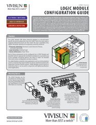
V I V I S U N<br />
LOGIC PULSE / TIMER<br />
Application Examples<br />
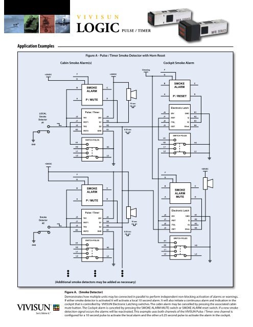
Figure A - <strong>Pulse</strong> / <strong>Timer</strong> Smoke Detector with Horn Reset<br />
Cabin Smoke Alarm(s)<br />
Cockpit Smoke Alarm<br />
Dimming<br />
F<br />
+28VDC<br />
F<br />
+28VDC<br />
G<br />
G<br />
B<br />
A<br />
SMOKE<br />
ALARM<br />
P / MUTE<br />
C<br />
D<br />
B<br />
A<br />
SMOKE<br />
ALARM<br />
P / RESET<br />
C<br />
D<br />
10 sec<br />
Electronic Latch<br />
LOCAL<br />
Smoke<br />
Detector<br />
#1<br />
J3<br />
J1<br />
J2<br />
<strong>Pulse</strong> / <strong>Timer</strong><br />
TR1<br />
28V<br />
/RST1<br />
Q1<br />
TR2<br />
Q2<br />
J4<br />
K4<br />
K2<br />
J4<br />
J1<br />
J2<br />
J3<br />
28V<br />
/RST<br />
/TGL<br />
/SET<br />
GND<br />
Q<br />
/Q<br />
Blink<br />
K1<br />
K2<br />
K3<br />
K4<br />
K3<br />
/RST2<br />
GND<br />
K1<br />
0.25 sec<br />
GND<br />
H1<br />
H2<br />
SWITCH POLES<br />
H3<br />
H1<br />
H2<br />
L1<br />
SWITCH POLES<br />
H3<br />
L1<br />
L2<br />
L3<br />
L2<br />
L3<br />
+28VDC<br />
+28VDC<br />
F<br />
F<br />
G<br />
G<br />
B<br />
A<br />
SMOKE<br />
ALARM<br />
P / MUTE<br />
C<br />
D<br />
B<br />
A<br />
SMOKE<br />
ALARM<br />
MUTE<br />
C<br />
D<br />
Smoke<br />
Detector<br />
#2<br />
J3<br />
J1<br />
J2<br />
K3<br />
<strong>Pulse</strong> / <strong>Timer</strong><br />
TR1<br />
28V<br />
/RST1<br />
Q1<br />
TR2<br />
Q2<br />
/RST2 GND<br />
J4<br />
K4<br />
K2<br />
K1<br />
0.25 sec<br />
10 sec<br />
J4<br />
J1<br />
J2<br />
J3<br />
Electronic Latch<br />
28V<br />
GND<br />
/RST<br />
Q<br />
/TGL<br />
/Q<br />
/SET<br />
Blink<br />
K1<br />
K2<br />
K3<br />
K4<br />
GND<br />
H1<br />
H2<br />
L1<br />
L2<br />
SWITCH POLES<br />
H3<br />
L3<br />
H1<br />
H2<br />
L1<br />
L2<br />
SWITCH POLES<br />
H3<br />
L3<br />
(Additional smoke detectors may be added as necessary)<br />
Figure A. (Smoke Detector)<br />
Demonstrates how multiple units may be connected in parallel to perform independent non-blocking activation of alarms or warnings.<br />
If either smoke detector is activated it will activate a local 10 second alarm. It will also initiate a continuous alarm and indication in the<br />
cockpit that is controlled by VIVISUN Electronic Latching switches. The cabin alarm may be cancelled by pressing the associated cabin<br />
mute button. The Cockpit alarm is canceled by pressing the SMOKE ALARM MUTE switch or SMOKE ALARM reset switch. If a new smoke<br />
detection signal occurs the alarms will be reactivated. This example uses both channels of the VIVISUN <strong>Pulse</strong> / <strong>Timer</strong>: one channel is<br />
configured for a 10 second pulse to activate the local alarm and the other a 0.25 second pulse to activate the alarm in the cockpit.
Application Examples<br />
V I V I S U N<br />
LOGIC PULSE / TIMER<br />
Figure B. (Speaker Inhibit)<br />
Pressing the RAAS SPEAKER<br />
switch will cause the RAAS<br />
speakers to toggle between<br />
the INHIBITED (OFF) and<br />
ACTIVE (ON). Any transition<br />
of weight on wheels will<br />
cancel the RAAS inhibit<br />
causing the RAAS speakers<br />
to become ACTIVE (ON).<br />
Figure B - <strong>Pulse</strong> / <strong>Timer</strong> Weight on Wheels<br />
+28VDC<br />
Dimming<br />
F<br />
G<br />
B<br />
A<br />
RAAS<br />
SPEAKER<br />
ACT<br />
INH<br />
C<br />
D<br />
Figure C. (5 Second Delay)<br />
Channel 1 is configured<br />
as negative (falling edge)<br />
detection with a 5 second<br />
active low pulse output.<br />
Channel 1 triggers channel<br />
2 at the end of the channel<br />
1 pulse. Channel 2 is<br />
configured as positive (rising<br />
edge) detection with an<br />
active high output. Note:<br />
The timing and delays may<br />
be selected from any of the<br />
standard factory programmable<br />
settings.<br />
GND<br />
Weight on<br />
Wheels<br />
J3<br />
J1<br />
J2<br />
K3<br />
(1)<br />
<strong>Pulse</strong> / <strong>Timer</strong><br />
TR1<br />
/RST1<br />
TR2<br />
/RST2<br />
28V<br />
Q1<br />
Q2<br />
GND<br />
(1) <strong>Pulse</strong> / <strong>Timer</strong> located in<br />
2nd VIVISUN switch body<br />
J4<br />
K4<br />
K2<br />
K1<br />
GND<br />
0.25 sec<br />
+28VDC<br />
J4<br />
J1<br />
J2<br />
J3<br />
H1<br />
H2<br />
L1<br />
L2<br />
Electronic Latch<br />
28V<br />
GND<br />
/RST<br />
Q<br />
/TGL<br />
/Q<br />
/SET<br />
Blink<br />
SWITCH POLES<br />
K1<br />
K2<br />
K3<br />
K4<br />
H3<br />
L3<br />
Ground to<br />
activate<br />
RAAS<br />
SPEAKER<br />
GND<br />
Figure C - <strong>Pulse</strong> / <strong>Timer</strong> 5 Second Delay<br />
+28VDC<br />
Figure D - <strong>Pulse</strong> / <strong>Timer</strong> Automatic Motor Stowed (Up) / Deployed (Down) Control<br />
Dimming<br />
F<br />
+28VDC<br />
Motor Power<br />
G<br />
<strong>Pulse</strong> / <strong>Timer</strong><br />
B<br />
STOWED<br />
C<br />
J3<br />
J1<br />
J2<br />
K3<br />
TR1<br />
/RST1<br />
TR2<br />
/RST2<br />
28V<br />
Q1<br />
Q2<br />
GND<br />
J4<br />
K4<br />
K2<br />
K1<br />
5 sec<br />
0.5 sec<br />
Stowed (Up)<br />
Limit Switch<br />
A<br />
J3<br />
J1<br />
J2<br />
TRANSIT<br />
<strong>Pulse</strong> / <strong>Timer</strong><br />
TR1<br />
28V<br />
/RST1<br />
Q1<br />
TR2<br />
Q2<br />
D<br />
J4<br />
K4<br />
K2<br />
10 sec<br />
Stow Relay<br />
M<br />
H1<br />
SWITCH POLES<br />
K3<br />
/RST2<br />
GND<br />
K1<br />
Deploy Relay<br />
H2<br />
L1<br />
L2<br />
H3<br />
L3<br />
Deployed (Down)<br />
Limit Switch<br />
H1<br />
H2<br />
L1<br />
SWITCH POLES<br />
H3<br />
10 sec<br />
L2<br />
L3<br />
GND<br />
GND<br />
Dimming<br />
F<br />
GND<br />
GND<br />
Figure D. (Motor Control)<br />
Demonstrates an automatic motor control using the VIVISUN<br />
<strong>Pulse</strong> / <strong>Timer</strong>. Pressing the STOWED switch will activate the<br />
Stow relay for a maximum of 10 second causing the motor to<br />
move to the stowed direction. When the Stowed limit switch<br />
is reached the VIVISUN <strong>Pulse</strong> / <strong>Timer</strong> will be automatically<br />
reset stopping the motor. Pressing the DEPLOYED switch will<br />
activate the Deployed relay for a maximum of 10 second causing<br />
the motor to move to the deployed direction. When the<br />
Deployed limit switch is reached the VIVISUN <strong>Pulse</strong> / <strong>Timer</strong> will<br />
be automatically reset stopping the motor. Note: if the motor<br />
is currently in transit pressing the other switch will reverse the<br />
direction of movement.<br />
G<br />
B<br />
A<br />
H1<br />
H2<br />
L1<br />
L2<br />
DEPLOYED<br />
TRANSIT<br />
SWITCH POLES<br />
C<br />
D<br />
H3<br />
L3<br />
GND<br />
The attached circuit diagrams are provided by <strong>Aerospace</strong> <strong>Optics</strong>, Inc. as a general example<br />
only. The recipient is solely responsible for actual design, electrical wiring, validation, testing,<br />
applicability and functionality of AOI’s product in customer’s specific application.<br />
© 2010 AEROSPACE OPTICS, INC. Data Sheet PT1.1-10-43