2013 VIVISUN LOGIC Module TDV p.1 - Aerospace Optics
2013 VIVISUN LOGIC Module TDV p.1 - Aerospace Optics
2013 VIVISUN LOGIC Module TDV p.1 - Aerospace Optics
- No tags were found...

Create successful ePaper yourself
Turn your PDF publications into a flip-book with our unique Google optimized e-Paper software.
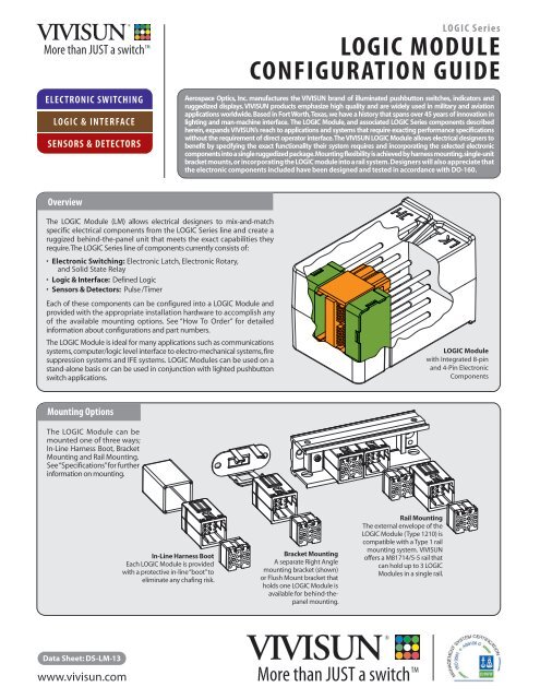
More than JUST a switch TMELECTRONIC SWITCHING<strong>LOGIC</strong> & INTERFACESENSORS & DETECTORS<strong>LOGIC</strong> Series<strong>LOGIC</strong> MODULECONFIGURATION GUIDE<strong>Aerospace</strong> <strong>Optics</strong>, Inc. manufactures the <strong>VIVISUN</strong> brand of illuminated pushbutton switches, indicators andruggedized displays. <strong>VIVISUN</strong> products emphasize high quality and are widely used in military and aviationapplications worldwide. Based in Fort Worth, Texas, we have a history that spans over 45 years of innovation inlighting and man-machine interface. The <strong>LOGIC</strong> <strong>Module</strong>, and associated <strong>LOGIC</strong> Series components describedherein, expands <strong>VIVISUN</strong>’s reach to applications and systems that require exacting performance specificationswithout the requirement of direct operator interface. The <strong>VIVISUN</strong> <strong>LOGIC</strong> <strong>Module</strong> allows electrical designers tobenefit by specifying the exact functionality their system requires and incorporating the selected electroniccomponents into a single ruggedized package. Mounting flexibility is achieved by harness mounting, single-unitbracket mounts, or incorporating the <strong>LOGIC</strong> module into a rail system. Designers will also appreciate thatthe electronic components included have been designed and tested in accordance with DO-160.OverviewThe <strong>LOGIC</strong> <strong>Module</strong> (LM) allows electrical designers to mix-and-matchspecific electrical components from the <strong>LOGIC</strong> Series line and create aruggized behind-the-panel unit that meets the exact capabilities theyrequire. The <strong>LOGIC</strong> Series line of components currently consists of:• Electronic Switching: Electronic Latch, Electronic Rotary,and Solid State Relay• Logic & Interface: Defined Logic• Sensors & Detectors: Pulse /TimerEach of these components can be configured into a <strong>LOGIC</strong> <strong>Module</strong> andprovided with the appropriate installation hardware to accomplish anyof the available mounting options. See “How To Order” for detailedinformation about configurations and part numbers.The <strong>LOGIC</strong> <strong>Module</strong> is ideal for many applications such as communicationssystems, computer/logic level interface to electro-mechanical systems, firesuppression systems and IFE systems. <strong>LOGIC</strong> <strong>Module</strong>s can be used on astand-alone basis or can be used in conjunction with lighted pushbuttonswitch applications.<strong>LOGIC</strong> <strong>Module</strong>with Integrated 8-pinand 4-Pin ElectronicComponentsMounting OptionsThe <strong>LOGIC</strong> <strong>Module</strong> can bemounted one of three ways;In-Line Harness Boot, BracketMounting and Rail Mounting.See “Specifications” for furtherinformation on mounting.In-Line Harness BootEach <strong>LOGIC</strong> <strong>Module</strong> is providedwith a protective in-line “boot” toeliminate any chafing risk.Bracket MountingA separate Right Anglemounting bracket (shown)or Flush Mount bracket thatholds one <strong>LOGIC</strong> <strong>Module</strong> isavailable for behind-thepanelmounting.Rail MountingThe external envelope of the<strong>LOGIC</strong> <strong>Module</strong> (Type 1210) iscompatible with a Type 1 railmounting system. <strong>VIVISUN</strong>offers a M81714/5-5 rail thatcan hold up to 3 <strong>LOGIC</strong><strong>Module</strong>s in a single rail.Data Sheet: DS-LM-13www.vivisun.comMore than JUST a switch TM
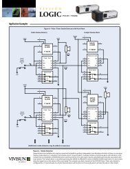
More than JUST a switch TM<strong>LOGIC</strong> SeriesCOMPONENT OPTIONS<strong>LOGIC</strong> MODULE (LM) OVERVIEWAbout <strong>VIVISUN</strong><strong>VIVISUN</strong>: More Than JUST A SwitchWhen you order from <strong>VIVISUN</strong>, you are getting much more than JUST theproduct you receive on your dock.• Quality: The <strong>Aerospace</strong> <strong>Optics</strong>, Inc. Quality Management System iscertified to AS9100: 2009. Our illuminated pushbutton switches arequalified under MIL-PRF-22885/90, /108, and /113. With DO-160 witnessedconformance, <strong>VIVISUN</strong> products are readily accepted worldwide.• Delivery: Our 99.5% on-time delivery is unmatched, and we combinethat performance with the best lead times in the industry.• Customer Service: From a knowledgeable and friendly voice toanswer your call to an automated shipping notice when your parts ship,we understand what it takes to support our customers. Using thepopular on-line <strong>VIVISUN</strong> Configurator allows customers to specify partnumbers from anywhere in the world and any time zone, and can takeadvantage of our technical support personnel available in the UnitedStates, United Kingdom, France, Germany and Italy.With over 45 years of experience in the ruggedized component industry,<strong>VIVISUN</strong> continues to deliver the highest quality products exactly whenyou need them.Component OptionsThe <strong>LOGIC</strong> <strong>Module</strong> (LM) can be populated with a wide variety ofavailable <strong>LOGIC</strong> Series components options described below. Thefollowing page describes the way these can be combined in a <strong>LOGIC</strong><strong>Module</strong> and includes ordering and part numbering information.Logic & InterfaceDefined Logic (8-pin)Replaces traditional diode and relay logic devices and can be usedto generate decision (Boolean logic) in a variety of 4 input/2 outputconfigurations.• Replaces power or ground drop-out relays• Boolean AND, OR, NOT (Inverter), and Exclusive OR capability• Dual Channel with 2 inputs each available in a single unit• Low power• Able to detect changes from either power or ground(INPUT A) J1(INPUT B) J2(GND) K1(OUTPUT Y) K2DL1, DL2, DL4Sensors & DetectorsJ4 (28 V)J3 (INPUT C)K4 (OUTPUT Z)K3 (INPUT D)Pulse/ Timer (8-Pin)An independent two-channel edge detector with the ability togenerate two independent outgoing signals. Signals can be high orlow and specified for defined time intervals from 125 milliseconds to10 seconds.• Timed device activation via pulse output (horn, buzzer, blinkingindicators)• Responds to any reciprocal transition such as “Weight On/OffWheels” or “Open/Close”• Channels may be connected in series for custom timing options• Integrated electrical circuit replaces external pulse generators,timers and time delay relays(RESET 1) J1(TRIGGER 2) J2(GND) K1(Q2) K2PT1J4 (28V)J3 (TRIGGER 1)K4 (Q1)K3 (RESET 2)(LM Code: DL1/_ /_ ,DL2/_ /_ & DL4/_ /_)(LM Code:PT1/___ /___ )See Data SheetDS-DL-13for completeinformation andadditional codingparametersSee Data SheetDS-PT1-11for completeinformation andadditional codingparametersElectronic SwitchingElectronic Latch (8-pin)Performs in a similar fashion to traditional magnetic or solenoidlatching switches but without mechanical components, is significantlylighter and requires a fraction of the power.• Replaces Magnetic or Solenoid Switches• Set, Reset and Toggle Capabilities• EL1 powers up in RESET state with BLINK off; EL2 powers up in theSET state with BLINK active• Ability to reset to an off or “safe” position on power up• Local, Remote and Lockout Control• Built-in Blink Circuitry(RESET) J1(TOGGLE) J2(GND) K1(Q) K2Solid State Relay (4-pin)Designed to replace a typical solid state relay without thechallenge of external packaging.• Switch power or ground up to 0.75 amps (AC or DC)• Convert logic level input to 28VDC aircraft power• Provide signal polarity reversal (High to Low or Low to High)• SSR activates when an input voltage of 4 to 6 VDC (SSR1L) or18 to 32 VDC (SSR1H) is applied• Provide output switching upto 32 VDC or 28 VAC rms(SWITCH) 1(IN) 2EL1 OR EL2SSR1HORSSR1LJ4 (28V)J3 (SET)K4 (BLINK)K3 (/Q)Electronic Rotary (8-pin)Provides the ability to use a single illuminated pushbuttonswitch to cycle through up to 4 latched states from either successiveswitch presses or from a remote source.• Hold the current latched state until either the next incrementinput (high to low transition) or a remote reset occurs• Sink up to 2 amps with a resistive load• Accepts reset from an external input for external override• Maintain operational statuswith power drop to 200ms(RESET) J1(/Q4) J2(GND) K1(/Q1) K2ER1J4 (28V)J3 (/INC)K4 (/Q3)K3 (/Q2)(LM Code: EL1 or EL2)(LM Code: ER1)4 (SWITCH)3 (IN) (LM Code:SSR1H or SSR1L)See Data SheetDS-EL1-10for completeinformationSee Data SheetDS-ER1-12for completeinformationSee Data SheetDS-SSR1-12for completeinformation
More than JUST a switch TM<strong>LOGIC</strong> SeriesHOW TO ORDERLOG IC MODULE (LM) OVERVI EWHow To OrderSpecifying a <strong>LOGIC</strong> <strong>Module</strong> requires a 2-line part number. Line 1 describes the type of housing and mounting options. Line 2 describes thespecific functionality of the <strong>LOGIC</strong> Series components desired. Once specified, ordering the part only requires using Line 1. Full sample partnumbers are provided below.<strong>Module</strong> Series and Size (See Table 2)Connector Plug (See Table 2)Table 2 – Accessory Part NumbersLine 1:Future OptionsLM-1210- X -MAAAA<strong>LOGIC</strong><strong>Module</strong>Code<strong>Module</strong> Series & SizeBoot (1)ConnectorPlug (2)Brackets (3)FlushMountRightAngleLM-1210-XFits Type 1 RailM81714/5-5(.80"W x .85"H x 1.33"L)22-00622-004 18-440 22-011 22-005Table 1: Accessory OptionsX No Conn. Plug or BracketE Including Conn. Plug OnlyR Including Right Angle Bracket OnlyT Incl. Conn. Plug & Right Angle BracketF Incl. Flush Mount Bracket OnlyG Incl. Conn. Plug & Flush Mt. BracketB Incl. Right Angle & Flush Mt. BracketsC Incl. Conn. Plug, Right Angle, & Flush Mt.BrcktsLine 2:L M ( __; __ ; __ ; __ )Five character codeassigned by <strong>VIVISUN</strong>or assigned on-lineusing the <strong>VIVISUN</strong>Configurator.(1) A Boot is included with each <strong>LOGIC</strong> <strong>Module</strong>. This P/N is for orderingreplacement boots.(2) Connector Plugs can be ordered separately or can be included withyour <strong>LOGIC</strong> <strong>Module</strong> by selecting codes E, T, G, or C from Table 1.Connector Plugs are removed using an Extraction Tool(AOI P/N 18-234).(3) Brackets can be ordered separately using the appropriate P/N andtype or can be included with your <strong>LOGIC</strong> <strong>Module</strong> be selecting codesR,T,F,G,B or C from Table 1.Line 2 describes the specific functionality internal to a configured <strong>LOGIC</strong> <strong>Module</strong>. See “Component Options” for a description of the types ofcomponents that can be included. Several components have complex part coding of their own and will require referring to the specific DataSheets for proper Line 2 configuration. Using the <strong>VIVISUN</strong> Configurator (www.vivisun.com) will ensure that the entire <strong>LOGIC</strong> <strong>Module</strong> part numberis configured properly.<strong>LOGIC</strong> <strong>Module</strong> (LM) – Only 4 Pin ComponentsPosition Schematic and Configuration Combination ExamplesSample P/N and Circuit DiagramConnector PlugLine 2:H JKL{4-pin} - <strong>LOGIC</strong> Component CodeO - Open CodeLM ( {4-pin} ;0; 0; 0 )LM-1210-X-MAAADLM (SSR1H; SSR1H; SSR1L;0)(SWITCH) H1(IN) H2(SWITCH) J1(IN) J2SSR1HSSR1HH4 (SWITCH)H3 (IN)J4 (SWITCH)J3 (IN)X configurations requireConnector Plug 18-440 tobe ordered separately.Replacing X with E denotesa part number with theConnector Plug included.LM ( __ ; __ ; __ ;__ )(SWITCH) K1(IN) K2SSR1LK4 (SWITCH)K3 (IN)LM ( {4-pin} ;{4-pin} ; 0; 0 )LM ( {4-pin} ;{4-pin} ; {4-pin} ; 0 )LM ( {4-pin} ; {4-pin} ;{4-pin} ; {4-pin} )OPEN<strong>LOGIC</strong> <strong>Module</strong> (LM) – With 8 Pin ComponentPosition Schematic and Configuration Combination ExamplesSample P/N and Circuit DiagramConnector PlugLine 2:H J & K LLM ( __ ; __ ; __ ){8-pin} - <strong>LOGIC</strong> Component Code{4-pin} - <strong>LOGIC</strong> Component CodeO - Open CodeLM ( 0 ; {8-pin} ; 0 )LM-1210-E-MAAAELM (SSR1H; DL4/F7/UD; SSR1L)(SWITCH) H1(IN) H2(INPUT A) J1(INPUT B) J2(/GND) K1(OUTPUT Y) K2SSR1HDL4H4 (SWITCH)H3 (IN)J4 (28V)J3 (INPUT C)K4 (OUTPUT Z)K3 (INPUT D)E denotes a part numberwith Connector Plug18-440 included. ReplacingE with X requires theConnector Plug to beordered seperately.LM ( {4-pin} ;{8-pin} ; 0 )LM ( {4-pin} ;{8-pin} ; {4-pin} )(SWITCH) L1(IN) L2SSR1LL4 (SWITCH)L3 (IN)