vivisun logic series - Aerospace Optics
vivisun logic series - Aerospace Optics
vivisun logic series - Aerospace Optics

You also want an ePaper? Increase the reach of your titles
YUMPU automatically turns print PDFs into web optimized ePapers that Google loves.
V I V I S U N<br />
LOGIC S E R I E S - I
V I V I S U N<br />
LOGIC S E R I E S - I<br />
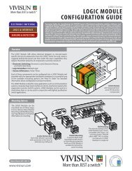
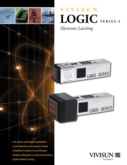
With the introduction of the VIVISUN LOGIC Series-I, the traditional<br />
vision and accepted performance of lighted pushbutton switches<br />
has changed forever. Switches traditionally require a physical<br />
action by an operator and the switch either maintains a latched<br />
position or returns to a normal state after a momentary trip. The<br />
operator may only control switches within physical reach and the<br />
function of a given switch is static. However, with the introduction<br />
of the VIVISUN LOGIC Series-I, design engineers may now look<br />
at traditional operator interface in a completely different way.<br />
A physical action is not always required to initiate the switch. A<br />
switch may now be controlled from a remote location allowing a<br />
set, reset or cancel from multiple locations outside the physical<br />
reach of the operator. The same switch may also function as a<br />
momentary or alternate action and depending on conditional<br />
inputs it also has the ability to reset to an off or “safe” position.<br />
The VIVISUN LOGIC Series-I switch performs in a similar fashion to<br />
traditional magnetic or solenoid latching switches but does not<br />
contain failure prone mechanical components, is significantly<br />
smaller and requires a fraction of the power. Refer to Table 3 for<br />
electrical performance and Figures 4 & 5 for mechanical detail.<br />
The LOGIC Series-I is contained within the same mechanical<br />
package as the existing VIVISUN 4-Pole or VIVISUN LR3 4-Pole<br />
switch.<br />
How it works:<br />
The LOGIC Series contains an integrated electrical circuit that<br />
accepts discrete inputs causing the switch to enter a sequence<br />
of different operating modes including Set, Reset or Toggle. The<br />
switch then responds with conditioned outputs that may be<br />
used to perform various system functions. Inputs may originate<br />
through external sensors, other switches or even through<br />
actuating the LOGIC Series switch which contains two traditional<br />
switch poles.<br />
The LOGIC Series is not only effective in simplifying operator<br />
interface but is also effective in simplifying complex circuit<br />
designs through eliminating external relays and reducing the<br />
overall bill of materials.<br />
To further understand the application possibilities refer to Figures<br />
1-3. Figure 1 highlights the local and remote control features as<br />
well as blink. It also demonstrates a remote lockout that can<br />
overide the function of a switch. Figure 2 details a simple safe<br />
mode function assuring the system automatically turns off when<br />
power is cycled. Figure 3 is a traditional Speaker Mute control.<br />
The VIVISUN LOGIC Series is packaged in a ruggedized MIL-SPEC<br />
design with the traditional high quality VIVISUN LED lighting. For<br />
details on environmental performance please refer to Table 4 and<br />
for lighting performance refer to the VIVISUN Data Sheet No. LED-<br />
12-2001-04 Rev. B, LR3-08-12, or 95-1-86-3 Rev. 2.<br />
Logic Module<br />
Functional Block Diagram<br />
Logic Module Functional Block Diagram<br />
J4<br />
J4<br />
J1<br />
J1<br />
J2<br />
J2<br />
J3<br />
J3<br />
H1<br />
H1<br />
H2<br />
H2<br />
L1<br />
L1<br />
L2<br />
L2<br />
/RESET<br />
/TOGGLE<br />
/SET<br />
+28 VDC<br />
Ground<br />
Logic<br />
Input<br />
Circuitry<br />
Logic<br />
Power<br />
Supply<br />
LOGIC Series<br />
LOGIC Series<br />
INPUT<br />
OUTPUT<br />
INPUT<br />
OUTPUT<br />
28v<br />
GND<br />
28v<br />
GND<br />
RESET<br />
Q<br />
RESET<br />
TOGGLE<br />
Q<br />
TOGGLE<br />
SET<br />
BLINK<br />
SET<br />
BLINK<br />
SWITCH POLES<br />
SWITCH POLES<br />
* Denotes double break option<br />
K1<br />
K1<br />
K2<br />
K2<br />
K3<br />
K3<br />
K4<br />
K4<br />
H4*<br />
H4<br />
H3<br />
H3<br />
L4 *<br />
L4<br />
L3<br />
L3<br />
Latch<br />
Circuitry<br />
Blink<br />
Circuitry<br />
QUIK-CONNECT TM Plug - Part No. 18-440<br />
Logic Series Part Numbering<br />
Part Numbering of the LOGIC Series follows <strong>Aerospace</strong> <strong>Optics</strong>’ standard format.<br />
• LED - XX-YY-YY-YYYYY (See LED Data Sheet for definition of remaining “Y” positions)<br />
• LR3 - XX-YY-YY-YYYYY (See LR3 Data Sheet for definition of remaining “Y” positions)<br />
• 95 - XX-YY-YY-YYYYY (See 95 Series Data Sheet for definition of remaining “Y” positions)<br />
• XX = “DP” for Indicator LOGIC Series-I<br />
• XX = “DJ” for 2 Pole Single Break LOGIC Series-I<br />
• XX = “DK” for 2 Pole Double Break LOGIC Series-I<br />
Logic<br />
Output<br />
Circuitry<br />
Q OUTPUT<br />
Q OUTPUT<br />
BLINK<br />
Logic Input Circuitry: provides a<br />
reliable diode isolated, buffered, and debounced<br />
input interface. The inputs are<br />
internally pulled up to approximately 18<br />
V. This provides simple reliable operation<br />
with either external switches or open<br />
drain drivers.<br />
Latch Circuitry: proven reliable latch<br />
circuitry that holds the current state<br />
and provides the set, reset and toggle<br />
features.<br />
Blink Circuitry: Free running 1 hertz<br />
square wave generator. This signal is<br />
then gated to provide a selectable blink<br />
output.<br />
Logic Output Circuitry: provides<br />
ground switched open drain output<br />
drivers that are both fused and surge<br />
protected.<br />
Power Supply: Efficient internal<br />
regulated supply that allows the unit to<br />
operate reliably on less than 4 mA.<br />
LOGIC Series-I requires the QUIK-CONNECT TM Plug as shown.<br />
A, B, C, D, F, G Lamp Contacts<br />
L1- L4, H1- H4 Switch Contacts<br />
J1- J4, K1- K4<br />
LOGIC Series Contacts<br />
(see description above)
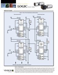
Logic Module Schematics<br />
Figure 1, presents a large cabin aircraft intercom<br />
system utilizing three LOGIC Series switches. The<br />
design allows the cockpit or the cabin to initiate<br />
a call but only the cockpit can cancel a call. The<br />
design has one cabin station but could have<br />
multiple cabin stations. When the cabin initiates<br />
a call, the CABIN CALL switch blinks until the<br />
cockpit responds. Once the call is initiated, only<br />
the cockpit can cancel the call or the call can<br />
be automatically cancelled if ATC COM is active.<br />
This is an example of the lock out feature which<br />
assures an internal call does not interfere with<br />
flight critical air traffic control communication.<br />
The circuit also has an EMERGENCY CALL switch<br />
to the cockpit that causes an EMER legend<br />
to illuminate in the cockpit and the pilot can<br />
acknowledge the emergency call even if ATC<br />
COM is active but does not open the channel<br />
until ATC COM is cancelled.<br />
Figure 2, is a reset assuring the system<br />
automatically reverts to an off or “safe” mode<br />
when master power is cycled.<br />
Figure 3, details an aircraft speaker mute function<br />
used to silence redundant or repetitive messages<br />
on the overhead speaker. The SPEAKER MUTE<br />
switch is a VIVISUN LOGIC Series and when<br />
actuated it is placed into a set mode that may be<br />
cancelled by a reset input provided via a physical<br />
actuation of the switch or automatically if the<br />
supplemental oxygen switch is selected.<br />
V I V I S U N<br />
LOGIC S E R I E S - I<br />
C<br />
A<br />
B<br />
I<br />
N<br />
F<br />
G<br />
B<br />
A<br />
J4<br />
J1<br />
J2<br />
J3<br />
H1<br />
H2<br />
L1<br />
L2<br />
F<br />
G<br />
B<br />
A<br />
J4<br />
J1<br />
J2<br />
J3<br />
H1<br />
H2<br />
L1<br />
L2<br />
Figure 1 - Large Cabin Communication System<br />
LOGIC Series<br />
28v<br />
/RST<br />
/TGL<br />
/SET<br />
PILOT<br />
CALL<br />
ICS<br />
GND<br />
Q<br />
Q<br />
Blink<br />
SWITCH POLES<br />
ICS<br />
LOGIC Series<br />
28v<br />
/RST<br />
/TGL<br />
/SET<br />
EMER<br />
COM<br />
COM<br />
GND<br />
Q<br />
Q<br />
Blink<br />
SWITCH POLES<br />
C<br />
D<br />
K1<br />
K2<br />
K3<br />
K4<br />
H3<br />
L3<br />
C<br />
D<br />
K1<br />
K2<br />
K3<br />
K4<br />
H3<br />
L3<br />
+28VDC<br />
ATC COM<br />
LINK<br />
Dimming<br />
F<br />
G<br />
B<br />
A<br />
J4<br />
J1<br />
J2<br />
J3<br />
H1<br />
H2<br />
L1<br />
L2<br />
F<br />
G<br />
B<br />
A<br />
LOGIC Series<br />
28v<br />
/RST<br />
/TGL<br />
/SET<br />
CABIN<br />
CALL<br />
ICS<br />
EMR<br />
GND<br />
Q<br />
Q<br />
Blink<br />
SWITCH POLES<br />
ATC<br />
COM<br />
C<br />
D<br />
K1<br />
K2<br />
K3<br />
K4<br />
H3<br />
L3<br />
C<br />
D<br />
C<br />
O<br />
C<br />
K<br />
P<br />
I<br />
T<br />
A1<br />
SWITCH POLES<br />
+28VDC<br />
Dimming<br />
B1<br />
Figure 2 - Auto Reset Figure 1 - Cabin and Flight Deck Example<br />
Figure to Safe 2 Mode - Relay Control Example<br />
Figure 3 - Speaker Mute Example<br />
B2<br />
Figure 3 - Speaker Mute Example<br />
F<br />
+28VDC Dimming F<br />
A2<br />
A3<br />
B3<br />
G<br />
G<br />
B<br />
HOT<br />
LIQUID<br />
C<br />
B<br />
SPEAKER<br />
C<br />
A<br />
ON<br />
D<br />
A<br />
MUTE<br />
D<br />
LOGIC Series<br />
LOGIC Series<br />
J4<br />
J1<br />
J2<br />
J3<br />
INPUT<br />
28v<br />
/RST<br />
/TGL<br />
/SET<br />
OUTPUT<br />
GND<br />
Q<br />
Q<br />
Blink<br />
K1<br />
K2<br />
K3<br />
K4<br />
Ground to Relay<br />
J4<br />
J1<br />
J2<br />
J3<br />
INPUT<br />
28v<br />
/RST<br />
/TGL<br />
/SET<br />
OUTPUT<br />
GND<br />
Q<br />
Q<br />
Blink<br />
K1<br />
K2<br />
K3<br />
K4<br />
Ground to<br />
Speaker Relay<br />
H1<br />
SWITCH POLES<br />
Oxygen<br />
Selected<br />
H1<br />
SWITCH POLES<br />
H2<br />
H3<br />
H2<br />
H3<br />
L1<br />
L1<br />
L2<br />
L3<br />
L2<br />
L3<br />
Pressing switch provides a ground signal that ground the relay and turns on<br />
the bottom legend. If the switch is pressed again the relay ground is removed<br />
Pressing switch provides a ground signal that can mute the speaker. If the switch<br />
is pressed again the speaker mute is cancelled.
V I V I S U N<br />
LOGIC S E R I E S - I<br />
Signal name<br />
QUIK-CONNECT<br />
Pin Number<br />
Function Active State Description<br />
/RESET (J1) Input Low (Ground) Forces Q OUTPUT to OFF (Open). Forces Q OUTPUT to ON (Ground). Forces BLINK to Steady ON (Ground). See Note 1.<br />
/TOGGLE (J2) Input Toggles Q OUTPUT and Q OUTPUT. Toggles blink mode. See Note 2.<br />
/SET (J3) Input Low (Ground) Forces Q OUTPUT to ON (Ground). Forces Q OUTPUT to OFF (Open). Initiates the 1Hz blink mode to BLINK Output.<br />
+28 VDC (J4) Power - Power (+10 VDC to +32 VDC)<br />
GROUND (K1) Common - Common for Power and Signals<br />
Q OUTPUT (K2) Output Note 1 Low (Ground) Open Drain Output. Forced OFF (Open) by /RESET Input. Forced ON (Ground) by /SET Input. Toggled by Falling Edge of /TOGGLE Input.<br />
Q OUTPUT (K3) Output Note 1 Low (Ground) Open Drain Output. Forced ON (Ground) by /RESET Input. Forced OFF (Open) by /SET Input. Toggled by Falling Edge of /TOGGLE Input.<br />
BLINK (K4) Output Note 1 Low (Ground) Open Drain Output: Forced ON (Ground) while /RESET is held Low (Ground).<br />
Inputs<br />
Outputs<br />
/SET /RESET /TOGGLE Q OUTPUT Q OUTPUT BLINK<br />
Low (Ground) High (Open) X Low (Ground) High (Open) 1 Hz BLINK mode<br />
R2 DIM Logic Series<br />
High (Open) Low (Ground) X High (Open) Low (Ground) Steady ON See Note 2<br />
Low (Ground) Low (Ground) X Low (Ground) Note 3 Low (Ground) Note 3 Steady ON See Note 2<br />
High (Open) High (Open) TOGGLE State TOGGLE State TOGGLE See Note 4<br />
Table 3.<br />
Logic Series-I Operating Parameters & Qualification<br />
Test Summary<br />
Note 1:<br />
Each Logic Series Output includes a Solid-state driver and an<br />
output filter designed to protect the output from transients<br />
and overload conditions.<br />
Note 2:<br />
BLINK Output is held Steady ON (Ground) while /RESET is held<br />
low. BLINK Output goes OFF (Open) when /RESET returns to<br />
the inactive high level. This feature provides essentially three<br />
states to the BLINK Output; OFF, ON and BLINK.<br />
Note 3:<br />
Illegal state.<br />
Note 4:<br />
/TOGGLE input causes BLINK Output to switch between 1 Hz<br />
Blink state and OFF (Open).<br />
Description Parameters<br />
Operating Parameters<br />
Maximum Operating Voltage<br />
Nominal Operating Voltage<br />
Minimum Operating Voltage<br />
Power Supply Input Current<br />
Reset From Power Loss<br />
Input Pulse Widths Minimum<br />
Reset<br />
Toggle<br />
Set<br />
Low Level Input Voltage (V IL<br />
)<br />
Low Level Input Current (I IL<br />
)<br />
Note: All signal inputs are diode isolated<br />
Output Load Capacity<br />
Resistive<br />
Motor<br />
Lamp<br />
Inductive<br />
Operational Life<br />
+32 VDC<br />
+28 VDC<br />
2.0 A<br />
1.0 A<br />
0.8 A<br />
0.8 A<br />
500,000 cycles at rated loads 0.94<br />
1.18<br />
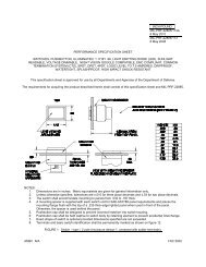
Figure 4.<br />
Unsealed Switch Dimensions for Vivisun LED and 95 (1)<br />
0.75<br />
Sq.<br />
+18 VDC<br />
LR3 4-pole Logic LR3 Series 4-pole Logic Series<br />
4mA maximum<br />
5 second maximum @ +25 C<br />
120 ms<br />
45 ms<br />
45 ms<br />
0.4 V dc maximum<br />
1mA maximum<br />
0.94<br />
PANEL CUTOUT<br />
.696 X .696<br />
+ 0.010, -0.0<br />
2.52<br />
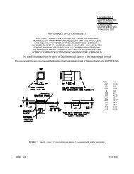
Figure 5.<br />
Unsealed Switch Dimensions for Vivisun LR3 (1)<br />
1.18<br />
2.67<br />
2.67<br />
Recommended Mounting Plate Cutout<br />
Dimensions for Unsealed Switches (1)<br />
<br />
<br />
<br />
<br />
<br />
<br />
<br />
<br />
<br />
Unsealed<br />
Recommended Mounting Plate Cutout<br />
Dimensions<br />
1.110<br />
for Unsealed Switches (1)<br />
.870<br />
.870<br />
1.110<br />
<br />
<br />
(1) See Data Sheet No. LED-12-2001-04 Rev B. for sealed switch dimensions.<br />
Unsealed<br />
<br />
<br />
1.000<br />
Temperature<br />
1.000<br />
Operating -55C to +85C<br />
Non–operating -55C to +85C<br />
PANEL CUTOUT<br />
1.110 X .870<br />
+ 0.010<br />
PANEL CUTOUT<br />
1.110 X .870<br />
+ 0.010<br />
1.200<br />
1.200<br />
Environmental and Performance Testing<br />
The Logic Series has been developed and tested to meet or exceed<br />
the following standards (see Table 4):<br />
RTCA/DO-160F<br />
MIL-PRF-22885G<br />
MIL-STD-202G<br />
MIL-STD-704D<br />
MIL-STD-461E<br />
(1) See Data Sheet No. LR3-08-12 for sealed switch dimensions.
V I V I S U N<br />
LOGIC S E R I E S - I<br />
Table 4. Logic Series-I Qualification Test Summary<br />
Test Description Specification Section Category Actual Test Conditions<br />
Temperature and Altitude<br />
RTCA/DO-160F<br />
MIL-STD-202G<br />
4<br />
105C<br />
108A<br />
D2<br />
Inductive<br />
-55°C to +85°C, 50,000 feet<br />
Thermal Shock MIL-STD-202G 107 A 12 cycles -55°C, +85°C<br />
Temperature Variation RTCA/DO-160F 5 S2 2 cycles -55C / +85C<br />
Humidity<br />
RTCA/DO-160F (1)<br />
MIL-STD-202G<br />
6<br />
106G<br />
B<br />
N/A<br />
240 Hours, 65C, >90% RH<br />
Operational Shock and Crash Safety<br />
RTCA/DO-160F (1)<br />
MIL-STD-202G<br />
MIL-STD-202G<br />
7<br />
213<br />
212<br />
E<br />
B<br />
A<br />
20G Acceleration<br />
75G Half-Sine<br />
Vibration<br />
Explosive Atmosphere<br />
Waterproofness Seal<br />
Sand and Dust<br />
Fungus Resistance<br />
Salt Fog<br />
RTCA/DO-160F (1)<br />
MIL-STD-202G<br />
RTCA/DO-160F<br />
MIL-STD-202G<br />
RTCA/DO-160F (1)<br />
MIL-PRF-22885G<br />
MIL-STD-108<br />
RTCA/DO-160F (1)<br />
MIL-STD-202G<br />
RTCA/DO-160F<br />
MIL-STD-22885G<br />
RTCA/DO-160F<br />
MIL-STD-202G<br />
8<br />
204<br />
9<br />
109C<br />
10<br />
4.7.20<br />
12<br />
110<br />
13<br />
3 . 5 . 2<br />
14<br />
101<br />
Z<br />
B<br />
A<br />
B<br />
R<br />
Splashproof<br />
D<br />
N/A<br />
F<br />
N/A<br />
T<br />
A<br />
10-2000 Hertz, 10G<br />
10-2000 Hertz, 15G peak<br />
15 gal/min, coarse spray, 10 Ft water head nozzle<br />
as required<br />
Silica media<br />
Compliance by material selection<br />
96 hour tests<br />
Magnetic Effect RTCA/DO-160F 15 A 1° deflection, 0.3m to 1.0m<br />
Power Input<br />
Aircraft Power<br />
RTCA/DO-160F<br />
MIL-STD-704D (3) 16<br />
N/A<br />
Polarity Reversal MIL-STD-704F 5 . 4 . 4<br />
Spike<br />
AF Conducted Susceptibility<br />
RTCA/DO-160F<br />
MIL-STD-461C<br />
17<br />
CS06<br />
RTCA/DO-160F<br />
MIL-STD-461E (2) 18<br />
CS101<br />
B<br />
N/A<br />
A<br />
Spike 1<br />
A<br />
Spike 1<br />
Z<br />
Curve 1<br />
10 to 32 VDC, 60V surge, 50ms. interrupt s<br />
Reversal of positive and negative connections<br />
Power, 600V, 10us, 50 ohm<br />
Power Input, 4V P-P, 1-150 KHz<br />
Induced Signal Susceptibility RTCA/DO-160F 19 CW 10,000V/m, 120A/m, 350-800 Hz<br />
RF Conducted Susceptibility<br />
RF Radiated Susceptibility<br />
RF Emissions<br />
Damped Sinusoidal Transient<br />
RTCA/DO-160F<br />
MIL-STD-461E (3) 20<br />
CS114<br />
RTCA/DO-160F<br />
MIL-STD-461E<br />
RTCA/DO-160F<br />
MIL-STD-461E<br />
20<br />
RS103<br />
21<br />
RE102<br />
RTCA/DO-160F<br />
MIL-STD-461E (2) 22<br />
CS116<br />
W<br />
Curve 4<br />
R<br />
Curve 4<br />
Cat B3K33<br />
N/A<br />
7.5V, 150mA, 10KHz-400MHz<br />
200V/m, 2 MHz-1GHz, TEMCell<br />
Includes CE101, CE102, RE101<br />
(By analysis)<br />
Waveform 3, 600V, 1 MHz, 10Mhz<br />
Lightning Induced Transient RTCA/DO-160F 22 Cat B3K33 Waveform 5A, 300V, 120us.<br />
Dielectric Withstanding MIL-STD-202G 301 N/A 1000 VAC<br />
Electrostatic Discharge RTCA/DO-160F 25 N/A 15,000V, 150pf, 330 ohms<br />
Fire, Flammability RTCA/DO-160F 26 C Behind the panel flammability<br />
Resistive Electrical Endurance MIL-PRF-22885G 4 . 7 . 28 . 2 N/A 2.0A, 510K cycles<br />
Motor Electrical Endurance MIL-PRF-22885G 4 . 7 . 28 . 2 N/A 1.0A, 5A Surge, 515K cycles<br />
Lamp Electrical Endurance MIL-PRF-22885G 4 . 7 . 28 . 2 N/A 0.75A, 7.5A Surge, 517K cycles<br />
Inductive Electrical Endurance MIL-PRF-22885G 4 . 7 . 28 . 2 N/A 1.0A, 0.2J, 578K cycles<br />
Mechanical Endurance MIL-PRF-22885G 4 . 7 . 29 N/A High resistance load, 1,115,000 cycles<br />
<strong>Aerospace</strong> <strong>Optics</strong> Inc.<br />
3201 Sandy Lane<br />
Fort Worth, TX 76112<br />
817 451-1141 (phone)<br />
817 654-3405 (fax)<br />
888-VIVISUN (848-4786)<br />
www.<strong>vivisun</strong>.com
© 2010 AEROSPACE OPTICS, INC. Data Sheet LS1-10-03 Rev. E