Modified resistance coefficient calculations
Modified resistance coefficient calculations
Modified resistance coefficient calculations

Create successful ePaper yourself
Turn your PDF publications into a flip-book with our unique Google optimized e-Paper software.
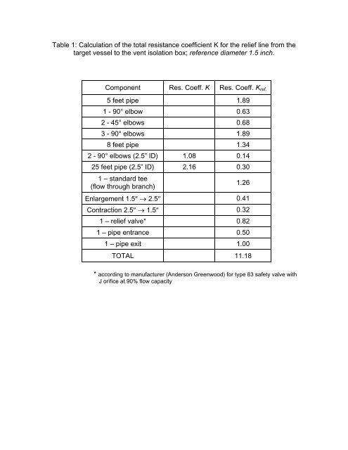
Table 1: Calculation of the total <strong>resistance</strong> <strong>coefficient</strong> K for the relief line from the<br />
target vessel to the vent isolation box; reference diameter 1.5 inch.<br />
Component Res. Coeff. K Res. Coeff. K ref.<br />
5 feet pipe 1.89<br />
1 - 90° elbow 0.63<br />
2 - 45° elbows 0.68<br />
3 - 90° elbows 1.89<br />
8 feet pipe 1.34<br />
2 - 90° elbows (2.5” ID) 1.08 0.14<br />
25 feet pipe (2.5” ID) 2.16 0.30<br />
1 – standard tee<br />
(flow through branch)<br />
1.26<br />
Enlargement 1.5″ → 2.5″ 0.41<br />
Contraction 2.5″ → 1.5″ 0.32<br />
1 – relief valve* 0.82<br />
1 – pipe entrance 0.50<br />
1 – pipe exit 1.00<br />
TOTAL 11.18<br />
* according to manufacturer (Anderson Greenwood) for type 83 safety valve with<br />
J orifice at 90% flow capacity
Table 2: Calculation of the total <strong>resistance</strong> <strong>coefficient</strong> for the relief line from the<br />
insulating vacuum vessel to the vent isolation box; reference diameter 4.0 inch.<br />
Component<br />
Resistance Coefficient<br />
K<br />
25 feet pipe 1.28<br />
1 – standard tee<br />
(flow through branch)<br />
1 – standard tee<br />
(flow through run)<br />
1.02<br />
0.36<br />
1 - gate valve 0.31<br />
1 - 90° elbow 0.51<br />
1 – rupture disk* 1.88<br />
1 – pipe entrance 0.50<br />
1 – pipe exit 1.00<br />
TOTAL 6.86<br />
* according to manufacturer (Fike) for SR-H rupture disks
Table 3: Resistance <strong>coefficient</strong>s for vent stack from the vent isolation box to the<br />
outside; reference diameter 6.0 inch.<br />
Component<br />
Resistance Coefficient<br />
K<br />
70 feet pipe 3.08<br />
5 – 90° elbows 2.25<br />
1 – standard tee, 6″ ID<br />
(flow through branch)<br />
0.90<br />
1 – lift check valve 9.00<br />
1 – pipe entrance 0.50<br />
1 – pipe exit 1.00<br />
TOTAL 16.73<br />
Conversion to 1.5 inch reference diameter pipe:<br />
4<br />
⎛ d ⎞<br />
a ⎛ 1.5 ⎞<br />
K<br />
⎜<br />
⎟<br />
a<br />
= Kb<br />
= 16.73⎜<br />
⎟ = 0.07<br />
⎝ db<br />
⎠ ⎝ 6.0 ⎠<br />
Conversion to 4.0 inch reference diameter pipe:<br />
K<br />
a<br />
= K<br />
b<br />
⎛ d<br />
⎜<br />
⎝ d<br />
a<br />
b<br />
⎞<br />
⎟<br />
⎠<br />
4<br />
⎛ 4.0 ⎞<br />
= 16.73⎜<br />
⎟<br />
⎝ 6.0 ⎠<br />
4<br />
4<br />
= 3.30
Steady State Pressure in the Target Vessel:<br />
The total <strong>resistance</strong> <strong>coefficient</strong> from the target vessel to the outside atmosphere<br />
is K = 11.18 + 0.07 = 11.25 (reference diameter: 1.5 inch).<br />
The steady-state target pressure was calculated with the following assumptions:<br />
Mass flow rate: w = 0.02 lb/s<br />
Flow temperature: T = 293 K, taken at the warmest point in the relief system.<br />
This will overestimate the inlet pressure p 1 , but this will be an error on the side of<br />
safety.<br />
Outlet pressure: p 2 = 14.7 psia, venting to air at the normal atmospheric pressure.<br />
Total <strong>resistance</strong> <strong>coefficient</strong>: K = 15.0<br />
Results:<br />
Sonic flow rate w sonic = 0.29 lb/s<br />
Target pressure p 1 = 17.0 psia.<br />
Steady State Pressure in the Insulating Vacuum Vessel:<br />
The total <strong>resistance</strong> <strong>coefficient</strong> from the insulating vacuum vessel to the outside<br />
atmosphere is K = 6.86 + 3.30 = 10.16 (reference diameter: 4.0 inch).<br />
The steady-state target pressure was calculated with the following assumptions:<br />
Mass flow rate: w = 0.5 lb/s<br />
Flow temperature: T = 293 K, taken at the warmest point in the relief system.<br />
This will overestimate the inlet pressure p 1 , but this will be an error on the side of<br />
safety.<br />
Outlet pressure: p 2 = 14.7 psia, venting to air at the normal atmospheric pressure.<br />
Total <strong>resistance</strong> <strong>coefficient</strong>: K = 15.0<br />
Results:<br />
Sonic flow rate w sonic = 2.10 lb/s<br />
Vacuum vessel pressure p 1 = 23.3 psia.<br />
Pressure difference inside-outside: Δp = p 1 – p 2 = 8.6 psid


![Mixed-mode Calculations within the Nuclear Shell Model [pdf]](https://img.yumpu.com/28265410/1/190x146/mixed-mode-calculations-within-the-nuclear-shell-model-pdf.jpg?quality=85)