VHF Communication Antennas VHF ... - Dallas Avionics
VHF Communication Antennas VHF ... - Dallas Avionics
VHF Communication Antennas VHF ... - Dallas Avionics

Create successful ePaper yourself
Turn your PDF publications into a flip-book with our unique Google optimized e-Paper software.
Navigation Navigation <strong>Antennas</strong> <strong>Antennas</strong><br />
<strong>Avionics</strong> & Accessories<br />
EDO Corp./Dorne & Margollin<br />
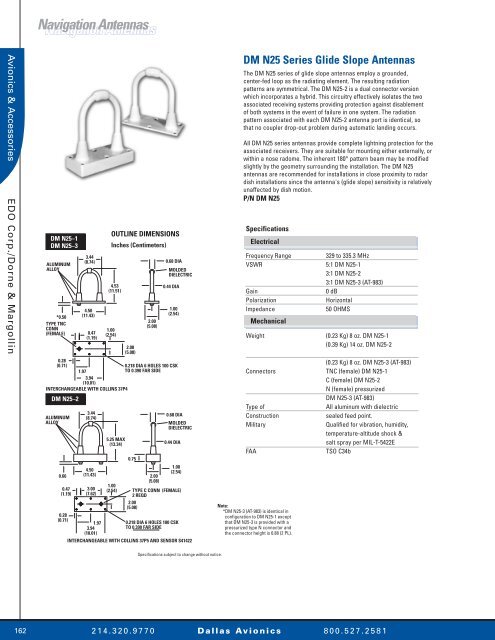
DM N25–1<br />
DM N25–3<br />
ALUMINUM<br />
ALLOY<br />
*0.50<br />
TYPE TNC<br />
CONN<br />
(FEMALE)<br />
3.44<br />
(8.74)<br />
4.50<br />
(11.43)<br />
0.47<br />
(1.19)<br />
OUTLINE DIMENSIONS<br />
Inches (Centimeters)<br />
4.53<br />
(11.51)<br />
1.00<br />
(2.54)<br />
2.00<br />
(5.08)<br />
2.00<br />
(5.08)<br />
0.28<br />
(0.71)<br />
0.218 DIA 6 HOLES 100 CSK<br />
1.97<br />
TO 0.390 FAR SIDE<br />
3.94<br />
(10.01)<br />
INTERCHANGEABLE WITH COLLINS 37P4<br />
DM N25–2<br />
ALUMINUM<br />
ALLOY<br />
0.66<br />
0.47<br />
(1.19)<br />
3.44<br />
(8.74)<br />
4.50<br />
(11.43)<br />
3.00<br />
(7.62)<br />
5.25 MAX<br />
(13.34)<br />
1.00<br />
(2.54)<br />
0.75<br />
2.00<br />
(5.08)<br />
0.68 DIA<br />
MOLDED<br />
DIELECTRIC<br />
0.44 DIA<br />
1.00<br />
(2.54)<br />
0.68 DIA<br />
MOLDED<br />
DIELECTRIC<br />
0.44 DIA<br />
1.00<br />
(2.54)<br />
TYPE C CONN (FEMALE)<br />
2 REQD<br />
2.00<br />
(5.08)<br />
0.28<br />
(0.71)<br />
1.97<br />
0.218 DIA 6 HOLES 100 CSK<br />
3.94<br />
TO 0.390 FAR SIDE<br />
(10.01)<br />
INTERCHANGEABLE WITH COLLINS 37P5 AND SENSOR S41422<br />
DM N25 Series Glide Slope <strong>Antennas</strong><br />
The DM N25 series of glide slope antennas employ a grounded,<br />
center-fed loop as the radiating element. The resulting radiation<br />
patterns are symmetrical. The DM N25-2 is a dual connector version<br />
which incorporates a hybrid. This circuitry effectively isolates the two<br />
associated receiving systems providing protection against disablement<br />
of both systems in the event of failure in one system. The radiation<br />
pattern associated with each DM N25-2 antenna port is identical, so<br />
that no coupler drop-out problem during automatic landing occurs.<br />
All DM N25 series antennas provide complete lightning protection for the<br />
associated receivers. They are suitable for mounting either externally, or<br />
within a nose radome. The inherent 180° pattern beam may be modified<br />
slightly by the geometry surrounding the installation. The DM N25<br />
antennas are recommended for installations in close proximity to radar<br />
dish installations since the antenna's (glide slope) sensitivity is relatively<br />
unaffected by dish motion.<br />
P/N DM N25<br />
Specifications<br />
Electrical<br />
Frequency Range<br />
329 to 335.3 MHz<br />
VSWR 5:1 DM N25-1<br />
3:1 DM N25-2<br />
3:1 DM N25-3 (AT-983)<br />
Gain<br />
0 dB<br />
Polarization<br />
Horizontal<br />
Impedance<br />
50 OHMS<br />
Mechanical<br />
Weight (0.23 Kg) 8 oz. DM N25-1<br />
(0.39 Kg) 14 oz. DM N25-2<br />
(0.23 Kg) 8 oz. DM N25-3 (AT-983)<br />
Connectors TNC (female) DM N25-1<br />
C (female) DM N25-2<br />
N (female) pressurized<br />
DM N25-3 (AT-983)<br />
Type of<br />
All aluminum with dielectric<br />
Construction<br />
sealed feed point.<br />
Military<br />
Qualified for vibration, humidity,<br />
temperature-altitude shock &<br />
salt spray per MIL-T-5422E<br />
FAA<br />
TSO C34b<br />
Note:<br />
*DM N25-3 (AT-983) is identical in<br />
configuration to DM N25-1 except<br />
that DM N25-3 is provided with a<br />
pressurized type N connector and<br />
the connector height is 0.88 (2 PL).<br />
Specifications subject to change without notice.<br />
162<br />
2 1 4 . 3 2 0 . 9 7 7 0 D a l l a s Av i o n i c s 8 0 0 . 5 2 7 . 2 5 8 1