VHF Communication Antennas VHF ... - Dallas Avionics
VHF Communication Antennas VHF ... - Dallas Avionics
VHF Communication Antennas VHF ... - Dallas Avionics

Create successful ePaper yourself
Turn your PDF publications into a flip-book with our unique Google optimized e-Paper software.
Couplers Couplers && Diplexers Diplexers<br />
<strong>Avionics</strong> & Accessories<br />
EDO Corp./Dorne & Margollin<br />
DM H21 through DM H24<br />
Antenna Couplers<br />
These Antenna Couplers are specifically designed to couple multiple<br />
receiver systems to a single antenna with a minimum of insertion loss.<br />
The couplers are designed to electronically split the received signals<br />
equally between the systems. In this manner, a single antenna may<br />
feed redundant systems or serve a dual-function role (e.g., Glide Slope<br />
and VOR/LOC).<br />
The ruggedly built couplers are housed in aluminum cases with all<br />
circuit elements fully encapsulated. General specifications applicable<br />
to all couplers are provided in this sheet, while Table 1 indicates the<br />
recommended function of the particular type.<br />
P/N DM H21-<br />
P/N DM H22-<br />
P/N DM H23-<br />
P/N DM H24-<br />
Specifications<br />
Electrical<br />
Frequency Range<br />
108 to 118 MHz<br />
329 to 335.3 MHz<br />
VSWR < 1.5:1<br />
Impedance<br />
50 OHMS<br />
Isolation<br />
VOR/LOC—VOR/LOC<br />
> 20 dB<br />
VOR/LOC from glide slope<br />
> 40 dB<br />
Glide slope from VOR/LOC<br />
> 14 dB<br />
Insertion Loss Glide slope port DM H22-1<br />
0.5 dB max & DM H23-1<br />
VOR/LOC port, DM H22-1 0.5 dB max<br />
VOR/LOC ports, DM H21-1,<br />
3.5 dB maximum including power split<br />
DM H23-1 & glide slope<br />
Ports DM H24-1<br />
TSO<br />
C34c, C35d, C36d, C40c<br />
Mechanical<br />
Weight<br />
4 oz. maximum<br />
0.75<br />
0.37<br />
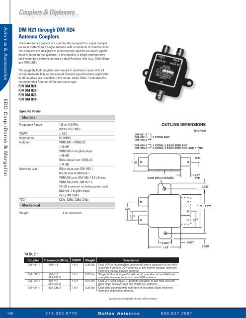
DM H21-1<br />
DM H22 -1<br />
DM H24-1<br />
3 CONN BNC<br />
OUTLINE DIMENSIONS<br />
Inches<br />
* DM H23-1 4 CONN, 2 EACH END BNC<br />
DM H23-2 4 CONN, 3 EACH END BNC AND 1 TNC<br />
1.03<br />
0.203 DIA (2 HOLES)<br />
*<br />
*<br />
0.44<br />
0.47<br />
TYP<br />
0.87<br />
1.75<br />
0.250<br />
2.375<br />
0.500<br />
1.87<br />
0.687<br />
0.250<br />
TABLE 1<br />
Coupler Frequency (MHz) VSWR Weight Description<br />
DM H21-1 108-118 1.5:1 0.25 lbs Dual VOR or dual marker beacon will permit operation of two NAV<br />
receivers from one VOR antenna or two marker beacon receivers<br />
from one marker beacon antenna.<br />
DM H22-1 108-118 1.5:1 0.25 lbs Single VOR and single GS will permit operation of one NAV and<br />
329-335.3 one glide slope receiver from one VOR antenna.<br />
DM H23-1 108-118 1.5:1 0.25 lbs Dual VOR and single GS permits operation of two NAV and one<br />
329-335.3 glide slope receiver from one VOR/LOC antenna.<br />
DM H24-1 329-335.3 1.5:1 0.25 lbs Dual glide slope permits operation of two glide slope receivers<br />
from one glide slope antenna.<br />
Specifications subject to change without notice.<br />
148<br />
2 1 4 . 3 2 0 . 9 7 7 0 D a l l a s Av i o n i c s 8 0 0 . 5 2 7 . 2 5 8 1