1952 RCA 21T176 - Early Television Foundation
1952 RCA 21T176 - Early Television Foundation
1952 RCA 21T176 - Early Television Foundation

Create successful ePaper yourself
Turn your PDF publications into a flip-book with our unique Google optimized e-Paper software.
JCTIONS<br />
ORE ATTEMPTING ALIGNMENT<br />
tl oscillator tube, (V18), from its socket.<br />
of withstanding considerable current drain. Connect the positive end<br />
junction of R95 & R96.<br />
zontal input of the oscilloscope for horizontal deflection.<br />
•JNECT<br />
:OPE<br />
'M<br />
e to pqinKg>.<br />
to chassis.<br />
'<br />
'<br />
ADJUST<br />
Al<br />
A2<br />
A3<br />
A4<br />
REMARKS<br />
Set bias pot. to -IVoIt, Adjust for MINIMUM<br />
deflection. Attenuate signal gen. to maintain<br />
-IVolt reading.<br />
Adjust for maximum deflection. Attenuate<br />
signal gen. to maintain 1 volt reading.<br />
F IG.4<br />
11,<br />
18.<br />
ALIGNMENT IN<br />
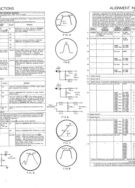
If the tuner is operating and requires only touch up alignment the<br />
completely realigned pre-set all adjustments to the approximate<br />
Pre-set A26 so the screw head is approximately 3/8 inch above t<br />
Do not change any adjustments on the antenna matching unit.<br />
Disconnect the coax link from terminal" A" of L24. Connect a 39S2<br />
Connect a clip lead from the tuner AGC terminal, (terminal 3) to<br />
During step 17 the signal generator is connected to the RF Amp.<br />
and the tube replaced in its socket. Connect the generator to the<br />
Set the fine tuning control 30 degrees clockwise from the mechan<br />
Connect the synchronized sweep voltage from the signal generat<br />
DUMMY<br />
ANTENNA<br />
1500MMF<br />
See fig.e<br />
SIGNAL<br />
GENERATOR<br />
COUPLING<br />
High side to pin 7, (grid)<br />
of 6BQ7, (VI). Low side<br />
to chassis.<br />
Across antenna terminal<br />
SIGNAL<br />
GENERATOR<br />
FREQUENCY<br />
Not used<br />
Not used<br />
MARKER<br />
GENERATOR<br />
FREQUENCY<br />
43. SMC<br />
(4001. mod)<br />
227MC<br />
unmod)<br />
CHAN<br />
2<br />
8<br />
A5<br />
A6<br />
19.<br />
183MC<br />
(10MC Swp)<br />
181. 25MC<br />
185.75MC<br />
up. to point<br />
side to chas-<br />
A7,A8<br />
Connect 330S2 resistor across R37, R38 and<br />
terminals 'A1" and V'of M6. Adjust for response<br />
curve similar to fig. I. Attenuate<br />
sweep gen. to maintain . 5 volt peak to peak<br />
response.<br />
20.<br />
Not used<br />
129MC<br />
6<br />
np. thru de-<br />
-obe, (fig. 2)<br />
of6AU6 (V3).<br />
; to chassis.<br />
ASaAlO<br />
Leave 330J3 resistors connected. Connect a<br />
180n resistorbetween pin 5 of V3 and junction<br />
of R29 and C40. Adjust for response similar<br />
to fig. 3.<br />
FIG.5<br />
21.<br />
22.<br />
"<br />
"<br />
8 SMC<br />
(10MC Swp)<br />
Not used<br />
83.25MC<br />
87, 75MC<br />
Not used<br />
up. to point<br />
side to chas-<br />
Remove all damping resistors. Set IF bias<br />
to -6 volts. Check for response curve similar<br />
to fig. 4. If necessary retouch A4 and A5 for<br />
proper response. Retouch A6 only if absolutely<br />
necessary. Incorrect adjustment of A6 will<br />
interfere with trap action.<br />
23.<br />
24.<br />
"<br />
Repeat step 18.<br />
"<br />
85MC<br />
(10MC Swp)<br />
83.25MC<br />
87. 75MC<br />
ator.<br />
25.<br />
Repeat step 19.<br />
ADJUST<br />
A14<br />
REMARKS<br />
Adjust for maximum deflection on VTVM. Adjust signal<br />
gen. to obtain 10 volt reading.<br />
2*. Repeat step 23, If necessary repeat steps 16, 17, and 20 until no fur<br />
27. see Fig. 8 Across antenna terminal. Not used 257MC<br />
13<br />
A15<br />
A16<br />
A17.A18<br />
A19<br />
Adjust for MINIMUM 4001 indication on scope. Repeat<br />
steps 10 and 11.<br />
Check the voltage at poinK^). II the voltage exceeds ±<br />
1. 5 volts, adjust A16 for zero voltage on VTVM between<br />
positive and negative peaks. Repeat adjustment of A15<br />
and A16 until VTVM reads less than 1 1. 5 volts with<br />
A15 adjusted for MINIMUM 4001 indication on scope.<br />
Adjust for maximum amplitude and symmetry as per<br />
Fig. 5.<br />
lent should not be attempted unless it has been definitely established<br />
required equipment cons sts of a sweep generator capable of at least<br />
nch. Misalignment of this unit can cause serious attenuation of the<br />
will not effect the alignm ;nt,<br />
mid be realigned,<br />
of L8 is alignment Poin \Sy, as shown on the schematic.<br />
mp. thru detrobe<br />
to<br />
>, Low side<br />
A17<br />
A18<br />
A19.A20<br />
Adjust for MINIMUM 400^ indication or scope.<br />
Adjust for MINIMUM 400% indication or scope.<br />
Connect a 3000 resistor from Point^to<br />
chassis. Adjust for response curve similar<br />
to Fig. 7. A19 controls the placement of the<br />
shoulder. A20 is adjusted to give maximum<br />
amplitude of .53MC marker consistant with<br />
curve shape shown in Fig. 7 .<br />
Repeat steps 14, 15 & 16 until no further improvement<br />
can be made.<br />
300-r<br />
BALANCED<br />
L-WV<br />
FIG.6<br />
TO 300j<br />
28.<br />
29.<br />
30.<br />
31.<br />
33.<br />
Repeat Step 20<br />
Repeat Step 19<br />
See Fig. 6 Across antenna terminal.<br />
213MC 211.25MC<br />
(10MC swp.) 215.75MC<br />
207MC 205.25MC<br />
(10MC swp.) 209.75MC<br />
201MC 199.25MC<br />
(10MC swp.) 203.75MC<br />
195MC 193.25MC<br />
{10MC swp.) 197.75MC<br />
189MC 187.25MC<br />
(10MC swp.) 191.75MC<br />
183MC 181.25MC<br />
(10MC swp.) 185.75MC<br />
177MC 175.25MC<br />
(10MC swp.) 179.75MC<br />
85MC<br />
(10MC swp.)<br />
79MC<br />
(10MC swp.)<br />
69MC<br />
(10MC swp.)<br />
63MC<br />
(10MC swp.)<br />
83.25MC<br />
87.75MC<br />
77.25MC<br />
81.75MC<br />
67.25MC<br />
71.75MC<br />
61. 25MC<br />
S5.75MC<br />
55.25MC<br />
59.75MC<br />
57MC<br />
(10MC swp.)<br />
32. See Fig. 6 Across antenna terminal. Not used 257MC<br />
Remove 39SJ Resistor and reconnect from<br />
V 251MC<br />
12<br />
245MC<br />
11<br />
239MC<br />
10<br />
233MC 9<br />
227MC 8<br />
221MC<br />
7<br />
129MC 6<br />
123MC 5<br />
113 MC<br />
4<br />
107MC 3<br />
link<br />
101MC<br />
tuner. Recheck<br />
2<br />
step<br />
FM TRAP<br />
If interference from an FM station is encountered adjust the FM<br />
in the area, they should be checked to make sure the trap is not<br />
13<br />
12<br />
11<br />
10<br />
9<br />
8<br />
7<br />
6<br />
5<br />
4<br />
3<br />
2<br />
13<br />
F IG.8<br />
F IG. 3