1952 RCA 21T176 - Early Television Foundation
1952 RCA 21T176 - Early Television Foundation
1952 RCA 21T176 - Early Television Foundation

Create successful ePaper yourself
Turn your PDF publications into a flip-book with our unique Google optimized e-Paper software.
HORIZ.<br />
INEARITY<br />
CONTROL<br />
WIDTH<br />
HORIZ.<br />
^FREQ.<br />
HEIGHT<br />
CONTROL<br />
HORIZ.<br />
DRIVE<br />
VERT.<br />
PEAKING<br />
CONTROL<br />
,.-<br />
/<br />
VERT.<br />
LINEARITY<br />
CONTROL<br />
VHORIZ.<br />
HOCK<br />
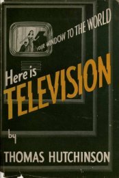
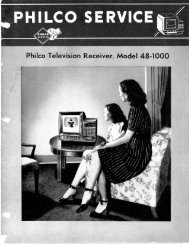
CABINET-REAR VIEW<br />
HORIZONTAL SWEEP CIRCUIT ADJUSTMENTS<br />
Turn the set on and tune in a TV station, preferably a test pattern.<br />
If the picture cannot be synchronized with the horizontal hold control, turn the hold control to the center of its range and adjust the horizontal frequency<br />
slug, (Bl), If adjustment of Bl will not synchronize the picture, turn the waveform slug, (B2), several turns out counter-clockwise and readjust Bl.<br />
Examine the width and horizontal linearity of the picture . If they are not approximately correct adjust the horizontal drive, width, and linearity as<br />
outlined under HORIZ. DRIVE, WIDTH, AND LINEARITY ADJUSTMENT.<br />
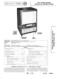
Connect the low capacity probe of an oscilloscope to terminal C of L38.<br />
Adjust the waveform slug, (B2), until the broad and narrow peaks of the waveform on the scope are of equal height as shown in figure 9. If necessary<br />
during adjustment of B2, readjust Bl to keep the picture synchronized.<br />
Turn the horizontal hold control to fully counter-clockwise, and momentarily interrupt the signal by switching to another channel and back again.<br />
If the picture is not out of synchronization turn Bl slightly and repeat the signal interruption until the picture is out of synchronization and shows<br />
several bars sloping downward to the left.<br />
Slowly turn the hold control clockwise and carefully note the least number of sloping bars present before the picture pulls into synchronization.<br />
If more than 3 bars are present adjust the locking range trimmer, (B3), slightly clockwise , if less than 2 bars are present adjust B3 slightly<br />
counter-clockwise.<br />
Repeat the check and adjustment of B3 until 2 to 3 bars are present at the pull-in point.<br />
Turn the horizontal hold control to fully clockwise .<br />
Adjust Bl until one bar, sloping downward to the right, appears in the picture. Then back off until the bar just moves off the picture leaving<br />
the picture in synchronization.<br />
HORIZONTAL DRIVE, WIDTH, AND LINEARITY ADJUSTMENTS<br />
Pre-set the adjustments as follows.<br />
Place the width link in the minimum width position, (top).<br />
Pre-set the width slug, (B6), to approximately mid-position.<br />
Pre-set the horizontal linearity slug, (B5), near minimum inductance, (counter-clockwise).<br />
Pre-set the horizontal linearity control near minimum resistance, (clockwise).<br />
Pre-set the horizontal drive trimmer, (B4), to minimum capacity, (counter-clockwise)<br />
Turn the set on and tune in a TV station, preferably a test pattern. Allow a few minutes tor set to warm up.<br />
If the raster is cramped or shows a bright vertical bar in the picture adjust B4 clockwise just enough to remove this condition.<br />
Adjust B5 clockwise until the picture of best linearity and maximum deflection, or the best compromise, are obtained and then one quarter turn more.<br />
Retouch B4 if necessary to obtain best results.<br />
Check the horizontal linearity at various settings of the brightness control. There should be no compression of the right side of the picture, and<br />
no appreciable change in linearityespecially at the extreme left side of the picture.<br />
If objectional changes do occur, turn B5 slightly clockwise and repeat the check.<br />
Adjust the width slug, (B6), until the picture is slightly wider than necessary to fill the mask horizontally. In the event of low line voltage, it may<br />
be necessary to move the width link to the lower position to obtain proper width. In this position the width coil, (B6) is inoperative.<br />
If the left side of the picture appears stretched, -adjust the horizontal linearity control counter-clockwise. If the left side of the picture appears cramped<br />
turn the linearity control clockwise. Whenever possible it is desirable to correct the linearity with the linearity control rather than the drive trimmer(B4).<br />
ADJUST FOR EQUAL PEAKS<br />
i<br />
FIG. 9<br />
PAGE1O