Diagram 2 - TwinHeat
Diagram 2 - TwinHeat
Diagram 2 - TwinHeat

Create successful ePaper yourself
Turn your PDF publications into a flip-book with our unique Google optimized e-Paper software.
9<br />
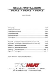
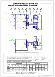
<strong>Diagram</strong> 2 – Connection to the heating system<br />
Open expansion vessel<br />
shutoff valve<br />
3 way thermostat<br />
controlled mixing valve<br />
(shunt valve)<br />
Manuel regulation valve<br />
(return valve)<br />
EÅ<br />
V1-V2<br />
V3<br />
V4<br />
shutoff valves on supply and return, in the boiler<br />
room. More can be installed if needed.<br />
Boiler shunt valve secure that the return water to the<br />
boiler always is over 60°C.<br />
To protect open expansion vessel against frost<br />
Can be thermostatic return valve<br />
Airing V5 Airing, possible automatic, placed where needed.<br />
Thermometer<br />
T1-T4<br />
Thermometer for supply, water return before and<br />
after shunt valve and for flue temperature<br />
Temperature sensor TF1 Temperature sensor to regulate shunt valve.<br />
Manometer M1 Manometer for boiler pressure.<br />
Pump P1 Circulation pump for heating system<br />
DIAGRAM 2